

Page 1
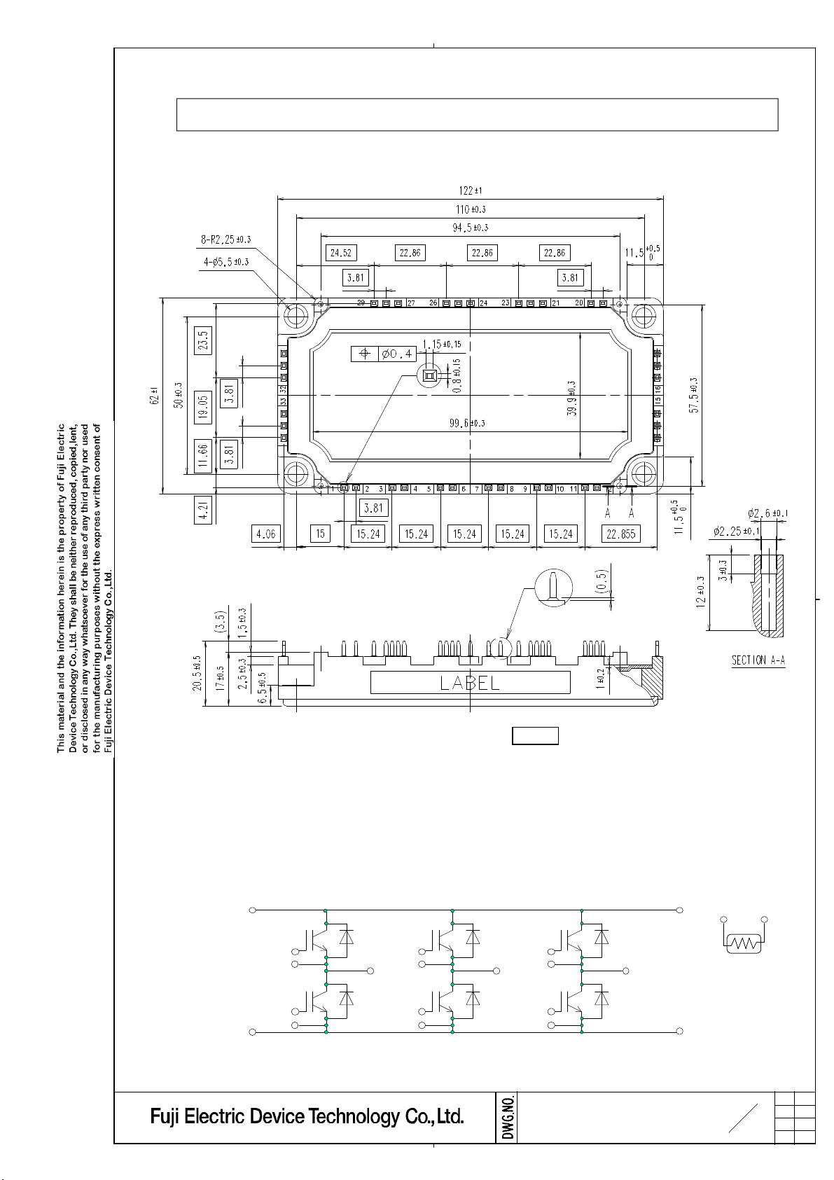
1. Outline Drawing ( Unit : mm )
6MBI150U4B-120-50
(RoHS compliant product)
2. Equivalent circuit
30,31,32
33,34,35
shows theoretical dimension.
( ) shows reference dimension.
16,17,18
1
2
3
4
5
6
U V W
27,28,29
7
8
9
10
11
12
21,22,2324,25,26
13,14,15
MS5F 6194
19 20
3
14
a
H04-004-03a
Page 2
Storage temperature
Lead resistance,
Zero gate voltage
Gate-Emitter
Gate-Emitter
T=25/50
o
C
T=100
o
C
T=25
o
C
Items
Tj=125
o
C
Tj=25
o
C
VF
Tj=25
o
C
Tj=125
o
C
VF
max.
Charact eristics
min.
typ.
Isolation
Tj=25
o
C
Tc=25
o
C
4. Electri cal characteristics ( at Tj= 25
o
C un less otherwise specified )
Tj=125
o
C
VCE(sat)
Tj=25
o
C
Tc=80
o
C
Tc=25
o
C
Tc=80
o
C
3. Abso lute Maximu m Ratings ( at Tc= 25
o
C un less otherwise specified )
Maxim um
Screw
Tj=125
o
C
VCE(sat)
Collector-Emitter voltage
Gate-Emitter voltage
Collector current
Collector Power Dissipation 1 device
Junction temperature
between terminal and copper base (*1)
voltage
between thermistor and others (*2)
Torque
Symbols Conditions
VCES
VGES
Ic Continuous
Icp 1ms
-Ic
-Ic pulse 1ms
Pc
Tj
Tstg
Rati ngs
1200
±20
200
150
400
300
150
300
735
+150
-40 to +125
Units
V
V
A
W
o
C
Viso AC : 1min. 2500 VAC
-Mounting (*3)
3.5
N m
(*1) All terminals should be connected together when isolation test will be done.
(*2) Two thermistor terminals should be connected together, each other terminals should be connected together
and shorted to base plate when isolation test will be done.
(*3) Recommendable Value : 2.5 to 3.5 Nm (M5)
Items ConditionsSymbols
VCE=1200V
VGE=0V
VCE=0V
VGE=±20V
VCE=20V
Ic=150mA
collector current
leakage current
threshold voltage
ICES - - 1.0
IGES
VGE(th)
Ic=150A
Collector-Emitter
(terminal)
VGE=15V
saturation voltage
(chip)
Input capacitance
Cies VCE=10V,VGE=0V,f=1MHz ton Vcc=600V - 0.32 1.20
Turn-on time
Inverter
tr Ic=150A - 0.10
tr(i) VGE=±15V - 0.03 -
Turn-off time
toff RG=2.2Ω tf - 0.07 0.30
IF=150A
Forward on voltage
(terminal)
VGE=0V
(chip)
Reverse recovery time
terminal-chip (*4)
Resistance
B value B
Thermistor
trr
IF=150A -
R lead 3.40 - mΩ
R
(*4) Biggest internal terminal resistance among arm.
- - 200
4.5
- 2.45 2.80
-
6.5 8.5
a
2.65
- 1.90 2.05
-
2.10 17 - nF
0.60
0.41 1.00
-
2.20 2.50
a
- 2.30 -
- 1.65 1.80
-
1.75 -
- 0.35
-
-
5000
465 495 520
3305
3375 3450 K
Units
mA
nA
V
V
us
V
us
-
Ω
MS5F 6194
4
a
14
H04-004-03a
Page 3

Lo go of production
Lo t.No.
Place of manufacturing (code)
9. Definiti ons of switchi ng time
- Products quantity in a packing box
10. Packing and Labeling
Display on the packing box
- Logo of production
- Type name
- Lot No
7. Appli cable category
8. Storage and transportati on not es
The module should be stored at a standard temperature of 5 to 35
o
C and humidity of 45 to 75% .
5. Thermal resistance characterist ics
Items Symbo ls Condit ion s Units
min .
typ.
max.
Charact eristics
150A 1200V
Contact Thermal resistance
6. Indicatio n on mo dule
Thermal resistance(1device)
(1 device) (*5)
Rth(j-c)
IGBT FWD - -
Rth(c-f) with Thermal Compound
-
-
0.05
(*5) This is the value which is defined mounting on the additional cooling fin with thermal compound.
6MBI150U4B-120-50
This specification is applied to IGBT-Module named 6MBI150U4B-120-50.
•
Be careful to solderability of the terminals if the module has passed over one
year from manufacturing date, under the above storage condition.
0.17
0.28
-
o
C/W
Store modules in a place with few temperature changes in order to avoid condensation on the
•
module surface.
Avoid exposure to corrosive gases and dust.
•
Avoid excessive external force on the module.
•
Store modules with unprocessed terminals.
•
Do not drop or otherwise shock the modules when transporting.
•
90%
~
~
0V
V
L
Vcc
R
G
V
GE
V
CE
Ic
GE
V
CE
Ic
0V
0A
t
r r
I
r r
Ic
~
90%
10%
10% 10%
t
r( i )
t
r
t
o n
~
V
CE
~
~
t
o f f
90%
t
f
0V
MS5F 6194
5
a
14
H04-004-03a
Page 4

11. List of material (材料リスト)
No. Parts Material (main) Ref.
(Total weight of soldering material(typ) : 9.1 g)
1 Base Plate Cu Ni plating
2 Terminal
3 Cover PPS resin UL 94V-0
4 Case PPS resin UL 94V-0
5 Isolation substrate
6 IGBT chip Silicon
7 Wiring Aluminum
8 Silicone Gel Silicone resin
9 Adhesive Silicone resin
10 Solder (Under chip) Sn/Ag base (Not drawn in above)
Solder
11 Sn/Ag base
(Under Isolation substrate )
12 Label Paper (Not drawn in above)
13 FWD chip Silicon
14 Ring Fe Trivalent Chromate treatment
15 Thermistor Lead glass
Cu
Al2O3 + Cu
Ni plating (Internal)
Lead free solder plating (External)
(Not drawn in above)
12. RoHS Directive Complianc e (RoHS 指令適用について)
本IGBTモジュールは富士電機デバイステクノロジーが発行しているRoHSに関する資料MS5F6209を適用する。
日本語版(MS5F6212)は参考資料とする。
The document (MS5F6209) about RoHS that Fuji Electric Device Technology issued is applied to this IGBT
Module. The Japanese Edition(MS5F6212) is made into a reference grade.
MS5F 6194
6
14
H04-004-03a
a
 Loading...