

Page 1
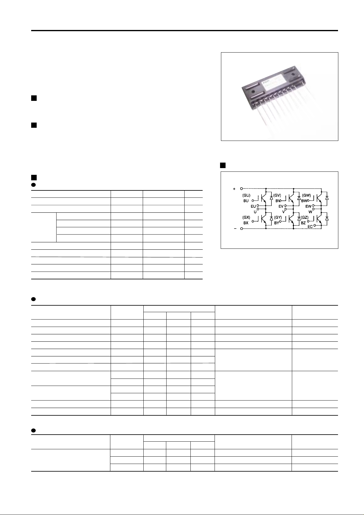
6MBI10GS-060
600V / 10A 6 in one-package
Features
· Compact Single in -line package
Applications
· Inverter for Motor drive
· AC and DC Servo drive amplifier
· Uninterruptible power supply
· Industrial machines, such as Welding machines
Maximum ratings and characteristics
Absolute maximum ratings (at Tc=25°C unless otherwise specified)
Item Symbol
Collector-Emitter voltage VCES
Gate-Emitter voltage VGES
Collector Continuous IC
current 1ms IC pulse
-IC
1ms -IC pulse
Max. power dissipation PC
Operating temperature Tj
Storage temperature Tstg
Isolation voltage Vis
Screw torque Mounting *1
*1 : Recommendable value : 1.3 to 1.7 N·m (M4)
Rating
600
±20
10
20
10
20
45
+150
-40 to +125
AC 2000 (1min.)
1.7
Unit
V
V
A
A
A
A
W
°C
°C
V
N·m
IGBT Modules
Equivalent Circuit Schematic
Electrical characteristics (at Tj=25°C unless otherwise specified)
Item Symbol Characteristics Conditions Unit
Min. Typ. Max.
Zero gate voltage collector current
Gate-Emitter leakage current
Gate-Emitter threshold voltage
Collector-Emitter saturation voltage
Input capacitance
Output capacitance
Reverse transfer capacitance
Turn-on time
Turn-off time
Diode forward on voltage
Reverse recovery time
保守廃止予定機種
Not recommend for new design.
ICES
IGES
VGE(th)
VCE(sat)
Cies
Coes
Cres
ton
tr
toff
tf
VF
trr
– – 1.0
– – 0.1
5.5 – 8.5
– – 2.8
– 650 –
– 150 –
– 36 –
– – 1.2
– – 1.0
– – 1.0
– – 0.35
– – 3.0
– – 0.3
VGE=0V , VCE=600V
VCE=0V, VGE=±20V
VCE=20V, IC=10mA
VGE=15V, IC=10A
VGE=0V
VCE=10V
f=1MHz
VCC=300V
IC=10A
VGE=±15V
RG=220ohm
IF=10A, VGE=0V
IF=10A, -di/dt=30A/µs, VGE=-10V
mA
µA
V
V
pF
µs
V
µs
Thermal resistance characteristics
Item Symbol Characteristics Conditions Unit
Min. Typ. Max.
Rth(j-c)
Thermal resistance Rth(j-c)
Rth(c-f)*2
*2 : This is the value which is defined mounting on the additional cooling fin with thermal compound
– – 2.78
– – 4.5
– 0.06 –
IGBT
Diode
the base to cooling fin
°C/W
°C/W
°C/W
Page 2
6MBI10GS-060
Characteristics (Representative)
IGBT Module
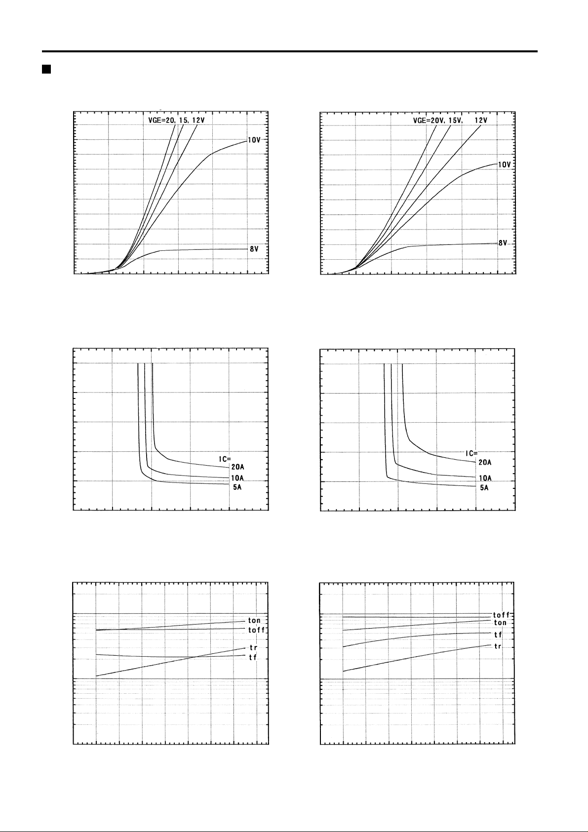
Collector current vs. Collector-Emitter voltage
Tj=25°C
20
18
16
14
12
10
8
6
Collector current : Ic [A]
4
2
0
0 1 2 3 4 5
Collector-Emitter voltage : VCE [V]
Collector-Emitter vs. Gate-Emitter voltage
Tj=25°C
10
Collector current vs. Collector-Emitter voltage
Tj=125°C
20
18
16
14
12
10
8
6
Collector current : Ic [A]
4
2
0
0 1 2 3 4 5
Collector-Emitter voltage : VCE [V]
Collector-Emitter vs. Gate-Emitter voltage
Tj=125°C
10
8
6
4
Collector-Emitter voltage : VCE [V]
2
0
0 5 10 15 20 25
Gate-Emitter voltage : VGE [V]
保守廃止予定機種
Switching time vs. Collector current
Vcc=300V, RG=220 ohm, VGE=±15V, Tj=25°C
1000
100
Not recommend for new design.
8
6
4
Collector-Emitter voltage : VCE [V]
2
0
0 5 10 15 20 25
Gate-Emitter voltage : VGE [V]
Switching time vs. Collector current
Vcc=300V, RG=220 ohm, VGE=±15V, Tj=125°C
1000
100
Switching time : ton, tr, toff, tf [n sec.]
10
0 2 4 6 8 10 12 14 16
Collector current : Ic [A]
Switching time : ton, tr, toff, tf [n sec.]
10
0 2 4 6 8 10 12 14 16
Collector current : Ic [A]
Page 3

6MBI10GS-060
IGBT Module
Switching time vs. RG
Vcc=300V , Ic=10A, VGE=±15V, Tj=25°C
5000
1000
100
Switching time : ton, tr, toff, tf [n sec.]
10
0 200 400 600 800 1000 1200
Gate resistance : RG [ohm]
Dynamic input characteristics
Tj=25°C
500
Switching time vs. RG
Vcc=300V , Ic=10A, VGE=±15V, Tj=125°C
5000
1000
100
Switching time : ton, tr, toff, tf [n sec.]
10
0 200 400 600 800 1000 1200
5000
25
Gate resistance : RG [ohm]
Capacitance vs. Collector-Emitter voltage
Tj=25°C
400
300
200
Collector-Emitter voltage : VCE [V]
100
0
0 10 20 30 40 50
Gate charge : Qg [nC]
保守廃止予定機種
Reversed biased safe operating area
+VGE=15V, -VGE = 15V, Tj = 125°C, RG = 220 ohm
100
90
80
70
60
50
40
30
Collector current : Ic [A]
20
10
0
0 100 200 300 400 500 600
Collector-Emitter voltage : VCE [V]
Not recommend for new design.
<<
>
20
15
10
5
0
1000
100
Gate-Emitter voltage : VGE [V]
Capacitance : Cies, Coes, Cres [pF]
10
0 5 10 15 20 25 30
10
1
Thermal resistance : Rth (j-c) [°C/W]
0.1
0.001 0.01 0.1 1
Collector-Emitter voltage : VCE [V]
Transient thermal resistance
Pulse width : PW [sec.]
Page 4

6MBI10GS-060
IGBT Module
Switching loss vs. Collector current
Vcc=300V, RG=220 ohm, VGE=±15V, Tj=125°C
1.0
0.9
0.8
0.7
0.6
0.5
0.4
0.3
0.2
Switching loss : Eon, Eoff, Err [mJ/pulse]
0.1
0.0
0 2 4 6 8 10 12 14 16
Collector current : Ic [A]
Forward current vs. Forward voltage
22
20
18
16
14
12
10
8
6
Forward current : IF [A]
4
2
0
0.0 0.5 1.0 1.5 2.0 2.5 3.0 3.5 4.0 4.5 5.0
Forward voltage : VF [V]
Switching loss vs. Gate resistance
Vcc=300V , Ic=10A, VGE=±15V, Tj=125°C
1.6
1.4
1.2
1.0
0.8
0.6
0.4
Switching loss : Eon, Eoff, Err [mJ/pulse]
0.2
0.0
0 200 400 600 800 1000 1200
Gate resistance : RG [ohm]
Reverse recovery characteristics
trr, Irr, vs. IF
100
10
Reverse recovery current : Irr [A]
Reverse recovery time : trr [n sec.]
1
0 2 4 6 8 10 12 14 16
Forward current : IF [A]
Outline Drawings, mm
保守廃止予定機種
Not recommend for new design.
 Loading...