

Page 1
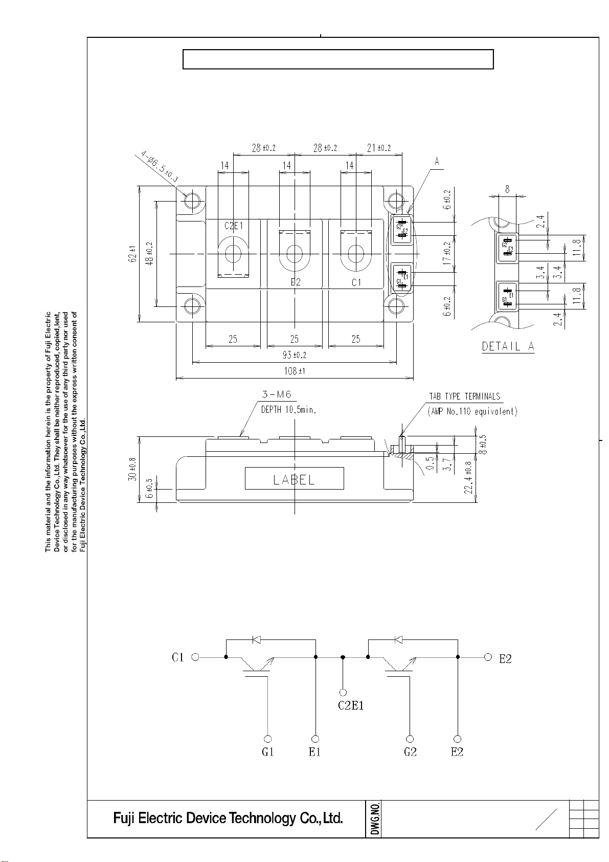
1. Outline Drawing ( Unit : mm )
2MBI300U4H-120
2. Equivalent circuit
MS5F6037
3
13
H04-004-03a
Page 2
3. Absolute Maximum Ratings ( at Tc= 25oC unless otherwise specified
)
C
C
Gate-Emitter
Gate-Emitter
)
Items
Collector-Emitter voltage
Gate-Emitter voltage
Collector current
Collector Power Dissipation 1 device
Junction temperature
Storage temperature
Isolation
voltage
Torque
(*1) All terminals should be connected together when isolation test will be done.
(*2) Recommendable Value : Mounting 2.5 to 3.5 Nm (M5 or M6)
(*3) Recommendable Value : Terminals 3.5 to 4.5 Nm (M6)
between terminal and copper base (*1)
Mounting (*2)
Terminals (*3)
Symbols Conditions
VCES 1200
VGES
Ic Continuous
Icp 1ms
-Ic
-Ic pulse
Pc
Tj
Tstg
Viso
-
1ms
AC : 1min. 2500
Tc=25oC
Tc=80
Tc=80oC
4. Electrical characteristics ( at Tj= 25oC unless otherwise specified
Items
Zero gate voltage
collector current
leakage current
threshold voltage
Collector-Emitter
saturation voltage
Input capacitance
Turn-on time
Turn-off time
Forward on voltage
Reverse recovery time
Lead resistance,
terminal-chip (*4)
(*4) Biggest internal terminal resistance among arm.
ICES
IGES
VGE(th)
VCE(sat)
(terminal)
VCE(sat)
(chip)
Cies
ton Vcc=600V - 0.32 1.20
tr Ic=300A - 0.10
tr(i)
toff RG=2.2Ω -
tf - 0.07 0.30
VF
(terminal)
VF
(chip)
trr us
R lead
VCE=1200V
VGE=0V
VCE=0V
VGE=±20V
VCE=20V
Ic=300mA
Ic=300A
VGE=15V
VCE=10V,VGE=0V,f=1MHz
VGE=±15V -
IF=300A
VGE=0V
IF=300A -
ConditionsSymbols
Tj=25oC
o
Tj=125
o
C
Tj=125oC
Tj=25oC
Tj=125oC
Tj=25oC
Tj=125oC
Characteristics
min.
- -
- - 800
4.5 6.5 8.5
- 2.10 2.25
-
- 1.90
-
-
- 0.03
-
- 1.95 -
- 1.65 1.80
-
-
Maximum
Ratings
o
o
C
typ. max.
2.30 -
2.10 34 - nF
0.41 1.00
1.85
1.75
- 0.35
0.53 - mΩ
400
300
800
600
300
600
1470
+150
-40 to +125
3.5
4.5
4.0
2.05
0.60
2.00
Units
V
V±20
A
W
o
C
VAC
N m
Units
mA
nA
V
V
us
V
-
MS5F6037
4
13
H04-004-03a
Page 3

)
5. Thermal resistance characteristics
Items Symbols Conditions Units
Thermal resistance(1device)
Contact Thermal resistance
(1 device) (*5)
Rth(j-c)
Rth(c-f) with Thermal Compound
IGBT FWD - -
(*5) This is the value which is defined mounting on the additional cooling fin with thermal compound.
Characteristics
min. typ. max.
-
-
0.0125
0 .085
6. Indication on module
Logo of production
2MBI300U4H-120
300A 1200V
Lot.No. Place of manufacturing (code
7. Applicable category
This specification is applied to IGBT-Module named 2MBI300U4H-120.
0.14
-
o
C/W
8. Storage and transportation notes
•
Store modules in a place with few temperature changes in order to avoid condensation on the
•
o
C and humidity of 45 to 75% .
module surface.
Avoid exposure to corrosive gases and dust.
•
Avoid excessive external force on the module.
•
Store modules with unprocessed terminals.
•
Do not drop or otherwise shock the modules when transporting.
•
9. Definitions of switching time
90%
~
~
0V
V
L
Vcc
R
G
V
GE
V
CE
Ic
GE
V
CE
Ic
0V
0A
t
r r
I
r r
Ic
~
90%
10%
10% 10%
t
r( i )
t
r
t
o n
~
CE
V
~
~
0V
90%
t
f
t
o f f
10. Packing and Labeling
Display on the packing box
- Products quantity in a packing box
MS5F6037
5
13
H04-004-03a
Page 4

11. Reliabi li ty test results
( 0 : 1 )
( 0 : 1 )
( 0 : 1 )
( 0 : 1 )
High temp. 125
( 0 : 1 )
-5
Reliability Test Items
Test
cate-
Test items Test methods and conditions
gories
1 Terminal Strength Pull force : 40N
(Pull test) Test time : 10±1 sec.
2 Mounting Strength Screw torque : 2.5 ~ 3.5 N・m (M5)
3.5 ~ 4.5 N・m (M6)
Test time : 10±1 sec.
3 Vibration Range of frequency : 10 ~ 500Hz
Sweeping time : 15 min.
Acceleration :
100m/s
Sweeping direction : Each X,Y,Z axis
Mechanical Tests
4 Shock Maximum acceleration :
Test time : 6 hr. (2hr./direction)
5000m/s
Pulse width : 1.0msec.
Direction : Each X,Y,Z axis
Test time : 3 times/direction
1 High Temperature Storage temp. : 125±5
Storage Test duration : 1000hr.
2 Low Temperature Storage temp. : -40±5
Storage Test duration : 1000hr.
3 Temperature Storage temp. : 85±2
Humidity Relative humidity : 85±5%
Storage Test duration : 1000hr.
4 Unsaturated Test temp. : 120±2
Pressurized Vapor Test humidity : 85±5%
Test duration : 96hr.
5 Temperature
Cycle Test temp. : Low temp. -40±5 ℃
℃
℃
2
℃
2
℃
Reference
norms
EIAJ ED-4701
(Aug.-2001 edit ion)
Test Method 401
Ⅰ
Method
Test Method 402
Ⅱ
method
Test Method 403
Reference 1
Condition code B
Test Method 404
Condition code B
Test Method 201
Test Method 202
Test Method 103
Test code C
Test Method 103
Test code E
Test Method 105
Number
of
sample
5 ( 0 : 1 )
5 ( 0 : 1 )
5 ( 0 : 1 )
5 ( 0 : 1 )
5
5
5
5
5 ( 0 : 1 )
Acceptance
number
Environment Tests
6 Thermal Shock
±5 ℃
RT 5 ~ 35 ℃
Dwell time : High ~ RT ~ Low ~ RT
1hr. 0.5hr. 1hr. 0.5hr.
Number of cycles : 100 cycles
+0
Test temp. :
High temp. 100
+5
Low temp. 0 -0℃
Used liquid : Water with ice and boiling water
Dipping time : 5 min. par each temp.
Transfer time : 10 sec.
Number of cycles : 10 cycles
℃
Test Method 307
Ⅰ
method
Condition code A
5
MS5F6037
6
13
H04-004-03a
 Loading...