

Page 1

NLS-HR32
Hand-held Barcode Scanner
User Guide
Page 2

Disclaimer
© 2018 Fujian Newland Auto-ID Tech. Co., Ltd. All rights reserved.
Please read through the manual carefully before using the product and operate it according to the manual. It is advised that you
should keep this manual for futur e reference.
Do not disassemble the device or remove the seal label from the device, doing so will void the product warranty provi ded by
Fujian Newland Auto-ID Tech. Co., Ltd.
All pictur es in this manual are for reference only and act ual product may differ. Regarding to the product modification and
update, Fujian Newland Auto-I D Tech. Co., Ltd. reserves the right to make changes to any soft ware or hardware to improve
reliability, function, or design at any time without notice. The information contained herein is subject to c hange without prior
notice.
The products depicted in this manual may include software copyrighted by Fujian Newland Auto-ID Tech. Co., Ltd or third party.
The user, corporation or individual, shall not duplicate, in whole or in part, distrib ute, modif y, decompile, disassemble, decode,
reverse engineer, rent, transfer or sublicense such software wit hout prior written consent from the copyright holders.
This manual is copyrighted. No part of this publicat ion may be reproduced, distributed or used in any form without written
permission from Newland.
Fujian Newland Auto-ID Tech. Co., Ltd. reserves the right to m ak e final interpretation of the statement above.
Fujian Newland Auto-ID Tech. Co., Ltd.
Newland Science & Technology Park, No.1 Rujiang West Rd., Mawei, Fuzhou, P.R.China
http://www.newlandaidc.com
Page 3

Revision History
Version Description Date
V1.0.0 Initial release. December 4, 2016
Page 4

Table of Contents
Revision History ....................................................................................................................................................................... - 3 -
Preface .......................................................................................................................................................................................... 1
Introduction ...................................................................................................................................................................... 1
Chapter Description ......................................................................................................................................................... 1
Explanation of Icons ......................................................................................................................................................... 2
Chapter 1 Getting Started ............................................................................................................................................................ 3
Introduction ...................................................................................................................................................................... 3
Features of the HR52 ....................................................................................................................................................... 3
Unpacking ........................................................................................................................................................................ 3
HR52 Scanner .................................................................................................................................................................. 4
Dimensions of the Scanner (unit: mm) ...................................................................................................................... 5
CD52 Cradle .................................................................................................................................................................... 6
Dimensions of the Cradle (unit: mm) ......................................................................................................................... 7
Mounting the Cradle ......................................................................................................................................................... 8
Horizontal Mount ....................................................................................................................................................... 8
Vertical Mount ........................................................................................................................................................... 8
Wall Mount .............................................................................................................................................................. 10
Connecting the Cradle to a Host .................................................................................................................................... 11
Using USB Cable .................................................................................................................................................... 11
Using RS-232 Cable ............................................................................................................................................... 12
Charging the Scanner Battery ........................................................................................................................................ 12
Pairing the Scanner to a Cradle ..................................................................................................................................... 13
Searching Paired Scanner(s) ......................................................................................................................................... 13
Wireless Communications .............................................................................................................................................. 13
Power On, Power Off, Reboot ........................................................................................................................................ 14
Maintenance................................................................................................................................................................... 14
Scanning Instructions ..................................................................................................................................................... 15
Chapter 2 EasySet ...................................................................................................................................................................... 16
Chapter 3 System Settings ........................................................................................................................................................ 17
Introduction .................................................................................................................................................................... 17
Barcode Programming ............................................................................................................................................ 17
Page 5

Command Programming ......................................................................................................................................... 17
EasySet Programming ............................................................................................................................................ 17
Programming Barcode/ Programmi ng Command/Function ............................................................................................ 18
Use of Programming Command ..................................................................................................................................... 19
Command Syntax ................................................................................................................................................... 19
Query Commands ................................................................................................................................................... 19
Responses .............................................................................................................................................................. 20
Examples ................................................................................................................................................................ 20
Use of Programming Barcodes ...................................................................................................................................... 21
Illumination ..................................................................................................................................................................... 22
Aiming ............................................................................................................................................................................ 23
Good Read LED ............................................................................................................................................................. 23
Good Read LED Duration ....................................................................................................................................... 24
Power On Beep .............................................................................................................................................................. 25
Good Read Beep ........................................................................................................................................................... 25
Good Read Beep Duration ...................................................................................................................................... 26
Good Read Beep Frequency .................................................................................................................................. 27
Good Read Beep Volume ....................................................................................................................................... 28
Good Read Vibration ...................................................................................................................................................... 28
Good Read Vibration Duration ................................................................................................................................ 29
Scan Mode ..................................................................................................................................................................... 30
Decode Session Timeout ............................................................................................................................................... 31
Image Stabilization Timeout (Sense Mode) .................................................................................................................... 32
Reread Timeout .............................................................................................................................................................. 33
Image Decoding Timeout ............................................................................................................................................... 34
Sensitivity (Sense Mode) ............................................................................................................................................... 35
Scanning Preference ...................................................................................................................................................... 36
Read Barcode On/Off ..................................................................................................................................................... 36
Make a Beeping Sound .................................................................................................................................................. 36
Smart Stand Mode ......................................................................................................................................................... 37
Decode Area .................................................................................................................................................................. 37
Image Flipping ................................................................................................................................................................ 40
Bad Read Message ........................................................................................................................................................ 41
Set Bad Read Message .......................................................................................................................................... 41
Power Off/Battery Off ..................................................................................................................................................... 42
Default Settings .............................................................................................................................................................. 42
Page 6

Factory Defaults ...................................................................................................................................................... 42
Custom Defaults ..................................................................................................................................................... 43
Query Scanner Information ............................................................................................................................................ 44
Query Product Name .............................................................................................................................................. 44
Query Firmware Version ......................................................................................................................................... 44
Query Decoder Version ........................................................................................................................................... 44
Query Data Formatter Version ................................................................................................................................ 45
Query Hardware Version ......................................................................................................................................... 45
Query Serial Number .............................................................................................................................................. 45
Query Manufacturing Date ...................................................................................................................................... 45
Query OEM Serial Number ..................................................................................................................................... 46
Query Cradle Information ............................................................................................................................................... 46
Query Model Number .............................................................................................................................................. 46
Query Firmware Version ......................................................................................................................................... 46
Query Hardware Information ................................................................................................................................... 47
Query Serial Number .............................................................................................................................................. 47
Query OEM Serial Number (ESN) .......................................................................................................................... 47
Query Manufacturing Date ...................................................................................................................................... 47
Query Remaining Battery of Scanner ............................................................................................................................. 48
Chapter 4 Wireless Communication s ....................................................................................................................................... 49
Operating Modes ............................................................................................................................................................ 49
Batch Mode .................................................................................................................................................................... 49
Batch Mode Options ............................................................................................................................................... 49
Prevent Same Barcode Storage .............................................................................................................................. 50
Batch Mode Transmit Delay .................................................................................................................................... 51
End of Transmission Message for Batch Mode ....................................................................................................... 52
Transmit Stored Data .............................................................................................................................................. 53
Auto Clear Stored Data after Transmission ............................................................................................................. 53
Query/Clear Stored Data in Flash ........................................................................................................................... 53
Retransmission .............................................................................................................................................................. 54
Transmission Timeout ............................................................................................................................................. 54
Retransmission Count ............................................................................................................................................. 55
Scanner(s) to Cradle Support......................................................................................................................................... 56
Wireless Communication Modes ............................................................................................................................. 56
Clear Pairing Info on Scanner/Cradle ..................................................................................................................... 56
Page 7

Set Date and Time ......................................................................................................................................................... 57
Query Current Date and Time ........................................................................................................................................ 57
Time Stamp .................................................................................................................................................................... 57
Set Time Stamp Format .......................................................................................................................................... 58
Chapter 5 RS-232 Interface ........................................................................................................................................................ 59
Introduction .................................................................................................................................................................... 59
Baud Rate ...................................................................................................................................................................... 59
Parity Check ................................................................................................................................................................... 60
Data Bit .......................................................................................................................................................................... 61
Stop Bit ........................................................................................................................................................................... 61
Hardware Auto Flow Control .......................................................................................................................................... 62
Chapter 6 USB Interface ............................................................................................................................................................ 63
Introduction .................................................................................................................................................................... 63
USB HID Keyboard ........................................................................................................................................................ 64
USB Country Keyboard Types ................................................................................................................................ 65
Emulate AL T+Keypad ............................................................................................................................................. 69
Code Page ....................................................................................................................................................... 70
Unicode Encoding ............................................................................................................................................ 72
Emulate Keypad with Leading Zero ................................................................................................................. 72
Function Key Mapping ............................................................................................................................................ 73
ASCII Function Key Mapping Table ........................................................................................................................ 74
ASCII Function Key Mapping Table (Continued) ..................................................................................................... 75
Inter-Keystroke Delay ............................................................................................................................................. 76
Convert Case .......................................................................................................................................................... 77
Emulate Numeric Keypad ....................................................................................................................................... 78
Polling Rate ............................................................................................................................................................. 80
USB CDC ....................................................................................................................................................................... 82
HID POS (POS HID Barcode Scanner) .......................................................................................................................... 83
Introduction ............................................................................................................................................................. 83
Access the Cradle with Your Program ..................................................................................................................... 83
Acquire Scanned Data ............................................................................................................................................ 84
Send Command to the Cradle ................................................................................................................................. 84
IBM SurePOS (Tabletop) ................................................................................................................................................ 85
IBM SurePOS (Handheld) .............................................................................................................................................. 85
VID/PID .......................................................................................................................................................................... 85
Page 8

Chapter 7 Symbologies .............................................................................................................................................................. 86
Introduction .................................................................................................................................................................... 86
Global Settings ............................................................................................................................................................... 86
Enable/Disable All Symbologies .............................................................................................................................. 86
Enable/Disable 1D Symbologies ............................................................................................................................. 86
Enable/Disable 2D Symbologies ............................................................................................................................. 87
Enable/Disable Postal Symbologies ....................................................................................................................... 87
1D Twin Code ......................................................................................................................................................... 88
Surround GS1 Application Identifiers (AI’s) with Parentheses ................................................................................. 89
Code 128 ....................................................................................................................................................................... 90
Restore Factory Defaults ........................................................................................................................................ 90
Enable/Disable Code 128 ....................................................................................................................................... 90
Set Length Range for Code 128 ............................................................................................................................. 91
EAN-8 ............................................................................................................................................................................ 92
Restore Factory Defaults ........................................................................................................................................ 92
Enable/Disable EAN-8 ............................................................................................................................................ 92
Transmit Check Character ...................................................................................................................................... 92
2-Digit Add-On Code ............................................................................................................................................... 93
5-Digit Add-On Code ............................................................................................................................................... 94
Convert EAN-8 to EAN-13 ...................................................................................................................................... 95
EAN-13 .......................................................................................................................................................................... 96
Restore Factory Defaults ........................................................................................................................................ 96
Enable/Disable EAN-13 .......................................................................................................................................... 96
Transmit Check Character ...................................................................................................................................... 97
2-Digit Add-On Code ............................................................................................................................................... 97
5-Digit Add-On Code ............................................................................................................................................... 98
Add-On Code Required .......................................................................................................................................... 98
EAN-13 Beginning with 290 Add-On Code Required .............................................................................................. 99
EAN-13 Beginning with 378/379 Add-On Code Required ....................................................................................... 99
EAN-13 Beginning with 414/419 Add-On Code Required ..................................................................................... 100
EAN-13 Beginning with 434/439 Add-On Code Required ..................................................................................... 100
EAN-13 Beginning with 977 Add-On Code Required ............................................................................................ 101
EAN-13 Beginning with 978 Add-On Code Required ............................................................................................ 101
EAN-13 Beginning with 979 Add-On Code Required ............................................................................................ 102
UPC-E .......................................................................................................................................................................... 103
Restore Factory Defaults ...................................................................................................................................... 103
Page 9

Enable/Disable UPC-E .......................................................................................................................................... 103
Transmit Check Character .................................................................................................................................... 103
2-Digit Add-On Code ............................................................................................................................................. 104
5-Digit Add-On Code ............................................................................................................................................. 105
Transmit Preamble Character ............................................................................................................................... 106
Convert UPC-E to UPC-A ..................................................................................................................................... 106
UPC-A .......................................................................................................................................................................... 107
Restore Factory Defaults ...................................................................................................................................... 107
Enable/Disable UPC-A .......................................................................................................................................... 107
Transmit Check Character .................................................................................................................................... 107
2-Digit Add-On Code ............................................................................................................................................. 108
5-Digit Add-On Code ............................................................................................................................................. 109
Transmit Preamble Character ............................................................................................................................... 110
Coupon ......................................................................................................................................................................... 111
UPC-A/EAN-13 with Extended Coupon Code ........................................................................................................ 111
Coupon GS1 Databar Output ................................................................................................................................ 112
Interleaved 2 of 5 ......................................................................................................................................................... 113
Restore Factory Defaults ...................................................................................................................................... 113
Enable/Disable Interleaved 2 of 5 ......................................................................................................................... 113
Set Length Range for Interleaved 2 of 5 ............................................................................................................... 114
Check Character Verification ................................................................................................................................. 115
Febraban ...................................................................................................................................................................... 116
Disable/Enable Febraban...................................................................................................................................... 116
Transmit Delay per Character ............................................................................................................................... 116
Transmit Delay per 12 Characters ........................................................................................................................ 119
ITF-14 .......................................................................................................................................................................... 121
Restore Factory Defaults ...................................................................................................................................... 121
Enable/Disable ITF-14 .......................................................................................................................................... 121
ITF-6 ............................................................................................................................................................................ 122
Restore Factory Defaults ...................................................................................................................................... 122
Enable/Disable ITF-6 ............................................................................................................................................ 122
Matrix 2 of 5 ................................................................................................................................................................. 123
Restore Factory Defaults ...................................................................................................................................... 123
Enable/Disable Matrix 2 of 5 ................................................................................................................................. 123
Set Length Range for Matrix 2 of 5 ....................................................................................................................... 124
Check Character Verification ................................................................................................................................. 125
Page 10

Code 39 ....................................................................................................................................................................... 126
Restore Factory Defaults ...................................................................................................................................... 126
Enable/Disable Code 39 ....................................................................................................................................... 126
Set Length Range for Code 39 ............................................................................................................................. 127
Check Character Verification ................................................................................................................................. 128
Transmit Start/Stop Character ............................................................................................................................... 129
Enable/Disable Code 39 Full ASCII ...................................................................................................................... 129
Enable/Disable Code 32 (Italian Pharma Code) ................................................................................................... 130
Code 32 Prefix ...................................................................................................................................................... 130
Transmit Code 32 Start/Stop Character ................................................................................................................ 131
Transmit Code 32 Check Character ...................................................................................................................... 131
Codabar ....................................................................................................................................................................... 132
Restore Factory Defaults ...................................................................................................................................... 132
Enable/Disable Codabar ....................................................................................................................................... 132
Set Length Range for Codabar ............................................................................................................................. 133
Check Character Verification ................................................................................................................................. 134
Start/Stop Character .............................................................................................................................................. 135
Code 93 ....................................................................................................................................................................... 136
Restore Factory Defaults ...................................................................................................................................... 136
Enable/Disable Code 93 ....................................................................................................................................... 136
Set Length Range for Code 93 ............................................................................................................................. 137
Check Character Verification ................................................................................................................................. 138
China Post 25 ............................................................................................................................................................... 139
Restore Factory Defaults ...................................................................................................................................... 139
Enable/Disable China Post 25 .............................................................................................................................. 139
Set Length Range for China Post 25 .................................................................................................................... 140
Check Character Verification ................................................................................................................................. 141
GS1-128 (UCC/EAN-128) ............................................................................................................................................ 142
Restore Factory Defaults ...................................................................................................................................... 142
Enable/Disable GS1-128....................................................................................................................................... 142
Set Length Range for GS1-128 ............................................................................................................................. 143
GS1 Databar (RSS) ..................................................................................................................................................... 144
Restore Factory Defaults ...................................................................................................................................... 144
Enable/Disable GS1 Databar ................................................................................................................................ 144
Transmit Application Identifier “01” ........................................................................................................................ 144
GS1 Composite (EAN·UCC Composite) ...................................................................................................................... 145
Page 11

Restore Factory Defaults ...................................................................................................................................... 145
Enable/Disable GS1 Composite ............................................................................................................................ 145
Enable/Disable UPC/EAN Composite ................................................................................................................... 145
Code 11 ........................................................................................................................................................................ 146
Restore Factory Defaults ...................................................................................................................................... 146
Enable/Disable Code 11 ........................................................................................................................................ 146
Set Length Range for Code 11 .............................................................................................................................. 147
Check Character Verification ................................................................................................................................. 148
Transmit Check Character .................................................................................................................................... 149
ISBN ............................................................................................................................................................................. 150
Restore Factory Defaults ...................................................................................................................................... 150
Enable/Disable ISBN ............................................................................................................................................ 150
Set ISBN Format ................................................................................................................................................... 151
ISSN ............................................................................................................................................................................. 152
Restore Factory Defaults ...................................................................................................................................... 152
Enable/Disable ISSN ............................................................................................................................................ 152
Industrial 25.................................................................................................................................................................. 153
Restore Factory Defaults ...................................................................................................................................... 153
Enable/Disable Industrial 25 ................................................................................................................................. 153
Set Length Range for Industrial 25 ....................................................................................................................... 154
Check Character Verification ................................................................................................................................. 155
Standard 25 .................................................................................................................................................................. 156
Restore Factory Defaults ...................................................................................................................................... 156
Enable/Disable Standard 25 .................................................................................................................................. 156
Set Length Range for Standard 25 ........................................................................................................................ 157
Check Character Verification ................................................................................................................................. 158
Plessey ........................................................................................................................................................................ 159
Restore Factory Defaults ...................................................................................................................................... 159
Enable/Disable Plessey ........................................................................................................................................ 159
Set Length Range for Plessey .............................................................................................................................. 160
Check Character Verification ................................................................................................................................. 161
MSI-Plessey ................................................................................................................................................................. 162
Restore Factory Defaults ...................................................................................................................................... 162
Enable/Disable MSI-Plessey ................................................................................................................................. 162
Set Length Range for MSI-Plessey ....................................................................................................................... 163
Check Character Verification ................................................................................................................................. 164
Page 12

Transmit Check Character .................................................................................................................................... 165
AIM 128 ........................................................................................................................................................................ 166
Restore Factory Defaults ...................................................................................................................................... 166
Enable/Disable AIM 128 ........................................................................................................................................ 166
Set Length Range for AIM 128 .............................................................................................................................. 167
ISBT 128 ...................................................................................................................................................................... 168
Restore Factory Defaults ...................................................................................................................................... 168
Enable/Disable ISBT 128 ...................................................................................................................................... 168
Code 49 ....................................................................................................................................................................... 169
Restore Factory Defaults ...................................................................................................................................... 169
Enable/Disable Code 49 ....................................................................................................................................... 169
Set Length Range for Code 49 ............................................................................................................................. 170
Code 16K ..................................................................................................................................................................... 171
Restore Factory Defaults ...................................................................................................................................... 171
Enable/Disable Code 16K ..................................................................................................................................... 171
Set Length Range for Code 16K ........................................................................................................................... 172
PDF417 ........................................................................................................................................................................ 173
Restore Factory Defaults ...................................................................................................................................... 173
Enable/Disable PDF417 ........................................................................................................................................ 173
Set Length Range for PDF417 .............................................................................................................................. 174
PDF417 Twin Code ............................................................................................................................................... 175
PDF417 Inverse .................................................................................................................................................... 176
Character Encoding .............................................................................................................................................. 176
PDF417 ECI Output .............................................................................................................................................. 177
Micro PDF417 .............................................................................................................................................................. 178
Restore Factory Defaults ...................................................................................................................................... 178
Enable/Disable Micro PDF417 .............................................................................................................................. 178
Set Length Range for Micro PDF417 .................................................................................................................... 179
QR Code ...................................................................................................................................................................... 180
Restore Factory Defaults ...................................................................................................................................... 180
Enable/Disable QR Code ...................................................................................................................................... 180
Set Length Range for QR Code ............................................................................................................................ 181
QR Twin Code ....................................................................................................................................................... 182
QR Inverse ............................................................................................................................................................ 183
Character Encoding .............................................................................................................................................. 183
QR ECI Output ...................................................................................................................................................... 184
Page 13

Micro QR Code ............................................................................................................................................................ 185
Restore Factory Defaults ...................................................................................................................................... 185
Enable/Disable Micro QR ...................................................................................................................................... 185
Set Length Range for Micro QR ............................................................................................................................ 186
Aztec ............................................................................................................................................................................ 187
Restore Factory Defaults ...................................................................................................................................... 187
Enable/Disable Aztec Code ................................................................................................................................... 187
Set Length Range for Aztec Code ......................................................................................................................... 188
Read Multi-barcodes on an Image ........................................................................................................................ 189
Set the Number of Barcodes ................................................................................................................................. 190
Character Encoding .............................................................................................................................................. 191
Aztec ECI Output .................................................................................................................................................. 191
Data Matrix ................................................................................................................................................................... 192
Restore Factory Defaults ...................................................................................................................................... 192
Enable/Disable Data Matrix ................................................................................................................................... 192
Set Length Range for Data Matrix ......................................................................................................................... 193
Data Matrix Twin Code .......................................................................................................................................... 194
Rectangular Barcode ............................................................................................................................................ 195
Data Matrix Inverse ............................................................................................................................................... 195
Character Encoding .............................................................................................................................................. 196
Data Matrix ECI Output ......................................................................................................................................... 196
Maxicode ...................................................................................................................................................................... 197
Restore Factory Defaults ...................................................................................................................................... 197
Enable/Disable Maxicode...................................................................................................................................... 197
Set Length Range for Maxicode ............................................................................................................................ 198
Chinese Sensible Code ................................................................................................................................................ 199
Restore Factory Defaults ...................................................................................................................................... 199
Enable/Disable Chinese Sensi ble Code ............................................................................................................... 199
Set Length Range for Chinese Sensi ble Code ...................................................................................................... 200
Chinese Sensible Twin Code ................................................................................................................................ 201
Chinese Sensible Code Inverse ............................................................................................................................ 202
GM Code ...................................................................................................................................................................... 203
Restore Factory Defaults ...................................................................................................................................... 203
Enable/Disable GM ............................................................................................................................................... 203
Set Length Range for GM ..................................................................................................................................... 204
Code One ..................................................................................................................................................................... 205
Page 14

Restore Factory Defaults ...................................................................................................................................... 205
Enable/Disable Code One ..................................................................................................................................... 205
Set Length Range for Code One ........................................................................................................................... 206
USPS Postnet .............................................................................................................................................................. 207
Restore Factory Defaults ...................................................................................................................................... 207
Enable/Disable USPS Postnet .............................................................................................................................. 207
Transmit Check Character .................................................................................................................................... 207
USPS Intelligent Mail ................................................................................................................................................... 208
Restore Factory Defaults ...................................................................................................................................... 208
Enable/Disable USPS Intelligent Mail ................................................................................................................... 208
Royal Mail .................................................................................................................................................................... 209
Restore Factory Defaults ...................................................................................................................................... 209
Enable/Disable Royal Mail .................................................................................................................................... 209
USPS Planet ................................................................................................................................................................ 210
Restore Factory Defaults ...................................................................................................................................... 210
Enable/Disable USPS Planet ................................................................................................................................ 210
Transmit Check Character .................................................................................................................................... 210
KIX Post ....................................................................................................................................................................... 211
Restore Factory Defaults ...................................................................................................................................... 211
Enable/Disable KIX Post ....................................................................................................................................... 211
Australian Postal .......................................................................................................................................................... 212
Restore Factory Defaults ...................................................................................................................................... 212
Enable/Disable Australian Postal .......................................................................................................................... 212
Specific OCR-B ............................................................................................................................................................ 213
Restore Factory Defaults ...................................................................................................................................... 213
Enable/Disable Specific OCR-B ............................................................................................................................ 213
Passport OCR .............................................................................................................................................................. 214
Restore Factory Defaults ...................................................................................................................................... 214
Enable/Disable Passport OCR .............................................................................................................................. 214
Chapter 8 Data Formatter ........................................................................................................................................................ 215
Introduction .................................................................................................................................................................. 215
Add a Data Format ....................................................................................................................................................... 215
Programming with Barcodes ................................................................................................................................. 215
Programming with Serial Commands .................................................................................................................... 218
Enable/Disable Data Formatter .................................................................................................................................... 219
Page 15

Non-Match Error Beep ................................................................................................................................................. 220
Data Format Selection ................................................................................................................................................. 221
Change Data Format for a Single Scan ....................................................................................................................... 222
Clear Data Format ........................................................................................................................................................ 223
Query Data Formats ..................................................................................................................................................... 223
Formatter Command Type 6 ........................................................................................................................................ 224
Send Commands .................................................................................................................................................. 224
Move Commands .................................................................................................................................................. 228
Search Commands ............................................................................................................................................... 230
Miscellaneous Commands .................................................................................................................................... 233
Chapter 9 Prefix & Suffix ......................................................................................................................................................... 239
Introduction .................................................................................................................................................................. 239
Global Settings ............................................................................................................................................................. 240
Enable/Disable All Prefixes/Suffixes...................................................................................................................... 240
Prefix Sequence ........................................................................................................................................................... 240
Custom Prefix ............................................................................................................................................................... 241
Enable/Disable Custom Prefix .............................................................................................................................. 241
Set Custom Prefix ................................................................................................................................................. 241
AIM ID Prefix ................................................................................................................................................................ 242
Code ID Prefix .............................................................................................................................................................. 243
Restore All Default Code IDs ................................................................................................................................ 243
Modify Code ID ..................................................................................................................................................... 243
Custom Suffix ............................................................................................................................................................... 252
Enable/Disable Custom Suffix ............................................................................................................................... 252
Set Custom Suffix ................................................................................................................................................. 252
Data Packing ................................................................................................................................................................ 253
Introduction ........................................................................................................................................................... 253
Data Packing Options ........................................................................................................................................... 253
Terminating Character Suffix ........................................................................................................................................ 255
Enable/Disable Terminating Character S uffix ........................................................................................................ 255
Set Terminating Character Suffix ........................................................................................................................... 255
Chapter 10 Batch Programming .............................................................................................................................................. 257
Introduction .................................................................................................................................................................. 257
Create a Batch Command ............................................................................................................................................ 258
Create a Batch Barcode ............................................................................................................................................... 258
Page 16

Use Batch Barcode ...................................................................................................................................................... 259
Appendix ................................................................................................................................................................................... 260
Digit Barcodes .............................................................................................................................................................. 260
Save/Cancel Barcodes ................................................................................................................................................. 263
Factory Defaults Table .................................................................................................................................................. 264
AIM ID Table ................................................................................................................................................................. 273
Code ID Table .............................................................................................................................................................. 275
Symbology ID Number ................................................................................................................................................. 277
ASCII T able .................................................................................................................................................................. 279
Unicode Key Maps ....................................................................................................................................................... 283
Page 17

Preface
Introduction
This manual provides detailed instructions for setting up and using the NLS-HR52 wireless 2D barcode scanner
(hereinafter referred to as “the NLS-HR32” or “the scanner”) and NLS-CD52 cradle (hereinafter referred to as “the
CD32” or
“the cradle”).
Chapter Description
Chapter 1 Getting Started
Chapter 2 EasySet
Chapter 3 System Settings
: Gives a general description of HR52 scanner and CD32 cradle.
: Introduces a useful tool you can use to set up NLS-HR32 scanner and
develop
new applications.
: Introduces three configuration methods and describes how to configure
general parameters of NLS-HR32 scanner.
Chapter 4 Wireless Communications : Describes how to configure the param eters necessary for wireless
communication between the scanner, cradle and host device.
Chapter 5 RS-232 Interface : Describes how to configure RS-232 com munication parameters.
Chapter 6 USB Interface : Describes how to configure USB communication parameters.
Chapter 7 Symbologies : Lists all c ompatible symbologies and describes how to configure the
relevant parameters.
Chapter 8 Data Formatter : Explains how to customize scanned data with the data formatter.
Chapter 9 Prefix & Suffix : Describes how to use prefix and suffix to customize scanned data.
Chapter 10 Batch Programming : Explains how to integrate a complex programming task into a single
barcode.
Appendix : Provides factory defaults table and a bunch of frequently used
programming barcodes.
1
Page 18

Explanation of Icons
This icon indicates something relevant to this manual.
This icon indicates this informati on r equires extra attention from the reade r.
This icon indicates handy tips that can help you use or configure the scanner wit h ease.
This icon indicates practical examples that can help you to acquaint yo ur self with operations.
2
Page 19

Introduction
Chapter 1 Getting Started
The HR52 wireless 2D barcode scanner reads a 1D or 2D barcode by capturing its image. Adopting the advanced
technology independently developed by Newland Auto-ID Tech, it provides five scan modes, including Level mode, Sense
mode, Continuous mode, Pulse mode and Batch mode, tailored to different scanning needs.
An illustrated introduction to the NLS-HR32 is included in this chapter. If you have an HR52 scanner at hand, make good
use of it to develop a better understanding of this manual. This chapter is written for normal users, maintenance staff and
software developers.
Features of the NLS-HR32
More reliable, more versatile, more efficient scanning solution
Bluetooth 5.0 radio (Frequency: 2402-2480MHz, RF Power: -0.69dBm)
User-friendly illumination & aim i ng
Ultra-rugged construction
Flexible mounting of cradle
Unpacking
Open the package and take out NLS-HR32 scanner and its accessories. Check to make sure everything on the packing
list is present and intact. If any contents are damaged or missing, please keep the original package and contact your
dealer immediately for after-sales service.
3
Page 20

HR52 Scanner
Good Read/Network LED:
Red LED flashes - Low battery alert.
Red LED on - Scanner not paired to cradle.
Blue LED flashes slowly - Paired but no connection
established.
Blue LED on - Connection established.
Blue LED flashes quickly - Batch transmission in
progress.
Green LED flashes once - Good read.
4
Page 21

Dimensions of the Scanner (unit: mm)
5
Page 22

PIN
Signal
Type
Function
6
CTS
I
7
RTS
O 8 GND
P
Ground
9
D-
I/O
CD52 Cradle
Red/Green LEDs:
Red LED on - No scanner placed on cradle.
Red LED flashes - Charging in progress, low
battery level.
Green LED flashes - Charging in progress ,
medium battery level.
Green LED on - Fully charged.
Data Port Pinouts:
1 NC - No connection
2 NC - No connection
3 VCC P Power+ (+5V)
4 TXD O RS-232 output
5 RXD I RS-232 input
Flow control signal
USB signal
10 D+ I/O
6
Page 23

Dimensions of the Cradle (unit: mm)
7
Page 24

Mounting the Cradle
The CD52 cradle can be set up in a horizo ntal or vertical position. Choose a mounting position that fits your need.
Horizontal Mount
The cradle is originally assembled in the horizontal position, as shown below.
Vertical Mount
1. Remove the clips from the horizontal crad le and then atta ch the clips for vert ical positio n to the correspondin g spots on
the cradle.
8
Page 25

2. Grab and pull the right board horiz ontally away from the cradle. Then rem ov e the main piece.
3. Insert the protruding part o n the left side of the main pie ce into the groove on the left board, so that the main piece is
vertical. Attach the right board to the main piece.
9
Page 26

Wall Mount
1. Remove the plate from the chassis by pressing the plastic clip F in with an appropriate tool.
2. Install the two plastic wall anchors in a wall and use screws to secure the plate to the wall with its A side f acin g the wall.
Slide the vertical cradle onto the plate.
10
Page 27

Connecting the Cradle to a Host
The cradle must be connected to a host in act ual application, such as PC, POS or any intellige nt terminal with USB or
RS-232 port, using a communication cable (USB or RS-232 cable).
USB
USB port on the Host
RS-232
RS-232 port on the Host
Note: Please check the port on the host and purchase the cable accordingly.
Using USB Cable
Connect the cradle to a Host using a USB cable with RJ45 and USB connectors:
1. Plug the RJ45 connector of the cable int o the data port on the cradle.
2. Plug the USB connector of the cable into the USB port on the Host.
3. Plug the supplied power adapter into the power jack on the cradle.
11
Page 28

Using RS-232 Cable
Connect the cradle to a Host using an RS-232 c able with RJ45 and RS-232 connector s and a power jack:
1. Plug the RJ45 connector of the cable into the data port on the cradle.
2. Plug the RS-232 connector of the cable into the RS-232 port on the Host.
3. Plug the supplied power adapter int o the power jack on the cradle.
Charging the Scanner Battery
To charge the scanner battery, insert the scanner in a powered cradle. You can check the charge status with the red and
green LEDs on the cradle.
Red LED steady on No scanner placed on cradle
Red LED flashes Charging in progress, low battery level
Green LED flashes Charging in progress, medium battery level
Green LED steady on Fully charged
12
Page 29

Pairing the Scanner to a Cradle
Before configuring or using the scan ner, you must pair it to a cradle first. A cradle can pair with up to seven scanners if
Multipoint-to-Point mode is enabled.
You need to perform the pairing operati on manually: After the scanner and cradle are turn ed on, insert the scanner in t he
cradle and then press the Pair button on the cradle. The scanner beeps on a successful pairing.
To unpair them, you may pair the scanner to another crad le, or scan the Clear Pairing Info on Cradle or Clear Pairing
Info on Scanner barcode in Chapter 4.
Searching Paired Scanner(s)
After the scanner(s) and cradle are turned on, press the Pair button on the cradle and the paired scanner(s) will beep.
Wireless Communications
The scanner can communicate with a remot e host using Bluetooth, or by pairing with a CD52 cradle that supports the
following interefaces:
Standard RS-232 connection to a host. For the cable connec tion instruc tions, see the “ Using RS-232 Cable” section
in this chapter. To learn how to configur e R S-232 communication parameters, see Chapter 5.
USB connection to a host. For the cab le connection ins tructions, se e the “Using USB Ca ble” section in this chapter.
To learn how to configure USB communication parameters, see Chapter 6.
For wireless communication parameters, s ee Chapter 4.
13
Page 30

Power On, Power Off, Reboot
Power on the scanner
Hold down the trigger on the scanner until it beeps.
Note: When using the scanner for the first time or after scanning the Battery Of f barcode in Chapter 3, you MUST insert
the scanner in a powered cradle to exit battery protection mode before turning it on.
Power off the scanner
Method 1: When in the Level scan mode, the scanner will automatically power off after 5 minutes of inac tivity.
Method 2: Scan the Power Off Scanner barcode in Chapter 3.
Reboot the scanner
If the scanner stops responding t o input or runs abnormally, use a straightened papercl ip to press and hold the Reset
button on the bottom of the scanner t o r eboot it.
Maintenance
The scan window should be kept clean.
Do not scratch the scan window.
Use soft brush to remove the stain from the scan window.
Use the soft cloth to clean the windo w, such as eyeglass cleaning cloth.
Do not spray any liquid on the scan window.
Do not use any detergent to clean other parts of the device except for water.
The warranty DOES NOT cover damages caused by inappropriate care and mai ntenance.
14
Page 31

Scanning Instructions
When the scanner is in the Level scan mode, you can follow the steps below to scan a bar code:
1. Press and hold the Trigger. Then the scanner will project a red aiming pattern.
2. Aim the aiming pattern across the center of barcode.
3. Release the Trigger when the aiming pattern goes off. If the barc ode is decoded successfully, the scanner will emit a
good read beep and the decoded data will be sent to the Host.
Note: For barcodes of the s ame batch, the scann er keeps a very high success ratio in certain distance which is regarded
as the optimal scanning distance.
15
Page 32

Chapter 2 EasySet
EasySet, developed by Fujia n Newland Auto-ID Tech. Co., Ltd., is a configuration tool for Newland’s 1D/2D handheld
barcode scanner, fixed mount barcode scanners and OEM scan engines. Its main features include:
View device & configuration information of online device
Configure device
Update firmware of online device
Load/modify existing XML configuration file; save current settings to an XML file
Create/print/save programming barcodes to a PDF or Word file
View/edit/save image stored on online device in the original image/BMP/JPG/TIFF format
Send serial commands to online device and receiv e device response
Supported languages: Chinese and English.
EasySet supports 32-bit/64-bit Microsoft WinXP/Win7/Win 8/Win 8.1/Win 10 operating systems.
EasySet can communicate with device via one of the following interface: RS-232, USB COM Port Emulation (UFCOM
driver required), USB CDC (UFCOM driver requ ired), USB DataPipe (UFCOM driver required), USB HID-POS.
16
Page 33

Enter Setup
Chapter 3 System Settings
Introduction
There are three ways to configure the HR 52: Barcode programming, command progr amming and Easyset programming.
Barcode Programming
The HR52 can be configured by scanning progr amming barcodes. All user programmable features/ options are described
along with their programming barcodes/commands in the following sections.
This programming method is mos t straightforward. However, it requires manually scan ning barcodes. As a result, err ors
are more likely to occur.
Command Programming
The HR52 can also be configured by serial commands (HEX) sent from the host devi ce.
Users can design an application program to send those command strings to the scanners to perform device configuration.
EasySet Programming
Besides the two methods mentioned above, you can conv eniently perform scanner configuration through EasySet too.
EasySet is a Windows-based configuration tool particularly des igned f or Newland pr oducts, enabling user s to gain ac cess
to decoded data and captured images and to configure scanners. For more information about this tool, refer to the EasySet
User Guide.
Before programming the scanner, you need to pair it to a cradle f irst. When programming the scanner
with serial commands or EasySet, you n eed to insert it in the paired cradle.
17
** Exit Setup
Page 34
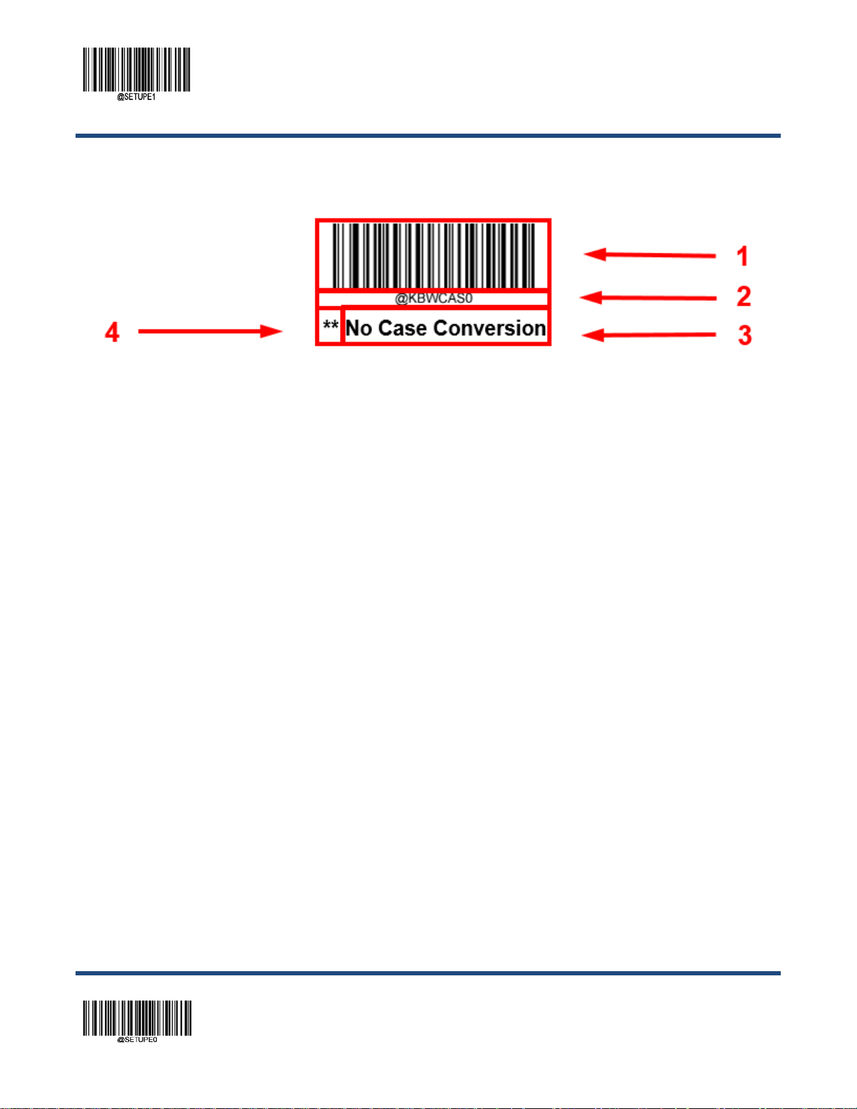
Enter Setup
Programming Barcode/ Programming Command/Function
The figure above is an example that shows you the programming barcode and command for the Enter Setup function:
1. The No Case Conversion barcode.
2. The No Case Conversion command.
3. The description of feature/ option.
4. ** indicates factory default setti ngs .
Note: “@” included i n the programming c ommand indicates permanent setting which means the setting will not be lost b y
removing power from the scanner or turning off or rebooting it; whereas “#” included in the programming command
indicates temporary setting which mea ns the setting will be lost by removing power from the scanner or turning off or
rebooting it.
** Exit Setup 18
Page 35

Enter Setup
Use of Programming Command
Besides the barcode programm ing method, the sca nner can also b e configured by s erial commands (HEX) sent from t he
host device. All commands must be entered in uppercase letters.
Command Syntax
Prefix StorageType Tag SubTag {Data} [,SubTag {Data}] [;Tag SubTag {Data}] […] Suffix
Prefix: “~<SOH>0000” (HEX: 7E 01 30 30 30 30), 6 characters.
StorageType: “@” (HEX: 40) or “#” (HEX: 23), 1 character. “@” means permanent setting which will not be lost by removing
power from the scanner or rebooting it; “#” means temporary setting which will be lost by removing power from the scanner
or rebooting it.
Tag: A 3-character case-sens itive field that identifies the desir ed command group. For example, all USB HI D Keyboard
configuration settings are ide ntified with a Tag of KBW.
SubTag: A 3-character case-sensitive fiel d that identifies the desired parameter within the tag group. For example, the
SubTag for the keyboard layout is CTY.
Data: The valu e for a feature or parameter setting, identified by the Tag and SubTag.
Suffix: “;<ETX>” (HEX: 3B 03), 2 characters.
Multiple commands can be is sued withi n on e Pr efi x/S uff i x sequenc e. For conf ig urat ion c om man ds, onl y t he Tag, SubTag,
and Data fields must be repeated for each command i n sequence. If an additio nal command is to be applied to the s ame
Tag, then the command is separated with a com ma (,) and only the SubTag and Data fields of the additional c ommands
are issued. If the additional command requires a different Tag field, the command is s eparated from previous command by
a semicolon (;).
Query Commands
For query commands, the entry in the Data field in the syntax above is one of the following characters means:
* (HEX: 2A) What is the scanner’s current value for the setting(s).
& (HEX: 26) What is the factory default value for the setting(s) .
^ (HEX: 5E) What is the range of possible values for the setting(s).
19
** Exit Setup
Page 36

Enter Setup
The value of the StoreType field in a query command c an be either “@” (HEX: 40) or “#” (HEX: 23).
A query command with the SubTag field omitted means to query all the settings concerning a tag. For example, to query all
the current settings about Code 11, you should enter 7E 01 30 30 30 30 40 43 31 31 2A 3B 03 (i.e.
~<SOH>0000@C11*;<ETX>).
Responses
Different from command sequence, the prefix of a response consis ts of the six characters of “<STX><SOH>0000” ( HEX:
02 01 30 30 30 30).
The scanner responds to serial comm ands with one of the following three re s ponses:
<ACK> (HEX: 06) Indicates a good command which has been processed.
<NAK> (HEX: 15) Indicates a good configuration command with its Data field entry out of the allowable range for this
Tag and SubTag combination (e.g. an entry for an inter-keystroke delay of 100 when the field will
only allow 2 digits), or an invalid query command.
<ENQ> (HEX: 05) Indicates an invalid Tag or SubTag command.
When responding, the scanner echoes bac k the command sequence with the status character above inserted directly
before each of the punctuation marks (the comma or semicolon) in the command.
Examples
Example 1: Enable Code 11, set the minimum and maximum lengths to 12 and 22 respectively.
Enter: 7E 01 30 30 30 30 40 43 31 31 45 4E 41 31 2C 4D 49 4E 31 32 2C 4D 41 58 32 32 3B 03
(~<SOH>0000@C11ENA1,MIN12,MAX22;<ETX>)
Response: 02 01 30 30 30 30 40 43 31 31 45 4E 41 31 06 2C 4D 49 4E 31 32 06 2C 4D 41 58 32 32 06 3B 03
(<STX><SOH>0000@C11ENA1<ACK>,MIN12<ACK>,MAX22<ACK>;<ETX>)
Example 2: Query the current minimum and maximum lengths of Code 11.
Enter: 7E 01 30 30 30 30 40 43 31 31 4D 49 4E 2A 2C 4D 41 58 2A 3B 03
(~<SOH>0000@C11MIN*,MAX*;<ETX>)
Response: 02 01 30 30 30 30 40 43 31 31 4D 49 4E 31 32 06 2C 4D 41 58 32 32 06 3B 03
(<STX><SOH>0000@C11MIN12<ACK>,MAX22<ACK>;<ETX>)
** Exit Setup 20
Page 37

Enter Setup
Use of Programming Barcodes
Scanning the Enter Setup barcod e can enable the scanner to enter the setup mode. Then you can scan a number of
programming barcodes to configure your scanner. To exit the setup mode, scan the Exit Setup barcode or a
non-programing barcode, or reboot t he s canner.
** Exit Setup
Enter Setup
Programming barcode data (i.e. the char acters under programming barcode) can be transmitted to the host device. Y ou
may scan the appropriate barcode belo w to enable or disable the transmissi on of programming barcode data t o the host
device.
** Do Not Transmit Programming Barcode Data
Transmit Programming Barcode Data
21
** Exit Setup
Page 38

Enter Setup
Illumination
A couple of illumination options are provided to improve the lighting conditions during every image c apture:
Normal: Illumination LEDs are turned on during image capture.
Always On: Illumination LEDs keep ON after the scanner is powered on.
Off: Illumination LEDs are OFF all the time.
** Normal
Off
Always On
** Exit Setup 22
Page 39

Enter Setup
Aiming
When scanning/capturing im age, the scanner projects an aiming patter n which allows positioning the target barcode within
its field of view and thus makes decoding easier.
Normal: The scanner projects an aiming pattern on ly during barcode scanning/capture.
Always On: Aiming pattern is constantly on after the sc anner is powered on.
Off: Aiming pattern is off all the time.
** Normal
Off
Always On
Good Read LED
The green LED can be programmed to be O n or Off to indicate good read.
** On
Off
23
** Exit Setup
Page 40

Enter Setup
Good Read LED Duration
This parameter sets the amount of time that the Good Read LED to remain on foll owing a good read.
** Short (20ms)
Medium (120ms)
Long (220ms)
Prolonged (320ms)
Custom (1 - 2,500ms)
Set the Good Read LED duration to 800ms:
1. Scan the Enter Setup barcode.
2. Scan the Custom barcode.
3. Scan the numeric barcodes “8”, “0” and “0” from the “Digit Barcodes” section in Appendi x.
4. Scan the Save barcode from the “Save/Cancel Barcodes” section in Appendix.
5. Scan the Exit Setup barcode.
** Exit Setup 24
Page 41

Enter Setup
Power On Beep
The scanner can be programmed to beep when it is powered on. Scan the Off barcode if you do not want a power on beep.
** On
Off
Good Read Beep
Scanning the Off barcode can turn off the beep that indicates successful decode; scanning the On barcode can turn it back
on.
** On
Off
25
** Exit Setup
Page 42

Enter Setup
Good Read Beep Duration
This parameter sets the length of t he beep the scanner emits on a good r ead. It is pr ogrammable in 1 ms increme nts from
20ms to 300ms.
Short (40ms)
** Medium (80ms)
Long (120ms)
Custom (20 – 300ms)
Set the Good Read Beep duration to 200ms:
1. Scan the Enter Setup barcode.
2. Scan the Custom barcode.
3. Scan the numeric barcodes “2”, “0” and “0” from the “D igi t Barcodes” section in Appendix.
4. Scan the Save barcod e from the “Save/Cancel Barcodes” section in Appendix.
5. Scan the Exit Setup barcode.
** Exit Setup 26
Page 43

Good Read Beep Frequency
This parameter is programmable in 1Hz increments from 20Hz to 20,000Hz.
Extra Low (800Hz)
** Medium (2730Hz)
Enter Setup
Low (1600Hz)
High (4200Hz)
Custom (20 - 20,000Hz)
Set the Good Read Beep frequency to 2,000Hz:
1. Scan the Enter Setup barcode.
2. Scan the Custom barcode.
3. Scan the numeric barcodes “2”, “0” , “0” and “0” from the “Digit Barcodes” sec tion in Appendix.
4. Scan the Save barcode from the “Save/Cancel Barcodes” section in Appendix.
5. Scan the Exit Setup barcode.
27
** Exit Setup
Page 44

Enter Setup
Good Read Beep Volume
** Loud
Low
Medium
Good Read Vibration
You may choose whether or not to let the scanner vibrate when a barcode is successfully read by scanning the appropriate
barcode below.
On
** Off
** Exit Setup 28
Page 45

Enter Setup
Good Read Vibration Duration
This parameter sets the length for the Good Read Vibration. It is programmable in 1ms increments from 1ms to 2,500ms.
Short (40ms)
** Medium (80ms)
Long (120ms)
Custom (1 – 2,500ms)
Set the Good Read Vibration duration to 200ms:
1. Scan the Enter Setup barcode.
2. Scan the Custom barcode.
3. Scan the numeric barcodes “2”, “0” and “0” from the “D igi t Barcodes” section in Appendix.
4. Scan the Save barcod e from the “Save/Cancel Barcodes” s ection in Appendix.
5. Scan the Exit Setup barcode.
29
** Exit Setup
Page 46

Enter Setup
Scan Mode
Level Mode: A trigger pull activates a decode session. The decode session cont inues until a barcode is decoded or the
decode session timeout expires or you release the tri gger .
Sense Mode: The scanner activates a decode session every time it detects a barcode presented to it. The decode session
continues until a barcode is decoded or the decode session timeout expires. Reread Timeout can avoid undesired
rereading of same barcode in a given p eriod of time. Sensitivity can change the S ense Mode’s sensibil ity to changes in
images captured. Image Stabilization Timeout gives the scanner time to adapt to ambient environment after it decodes a
barcode and “looks” for another.
Continuous Mode: The scanner automatically starts one decode session after another. To suspend/resume barcode
reading, simply press the trigger. Reread Timeout can av oid undesired rereading of same barcode in a given perio d of
time.
Pulse Mode: When the trigger is pulled a nd released, scanning is activated until a barcode is deco ded or the decode
session timeout expires (The decode session timeout begins when the trigger is released).
Batch Mode: A trigger pull act ivat es a roun d of mult ipl e de code ses s ions. This round of multiple scans continues until you
release the trigger. Rereading the same barcode is not allowed in the same round.
** Level Mode
Continuous Mode
Batch Mode
Sense Mode
Pulse Mode
** Exit Setup 30
Page 47

Enter Setup
Decode Session Timeout
This parameter sets the maximum time decode session continues during a scan attempt. It is programmable in 1ms
increments from 100ms to 3,600,000ms. When it is set to 0, t he timeout is infinite. The default setting is 3,000ms.
Decode Session Timeout
Set the decode session timeout to 1,500m s:
1. Scan the Enter Setup barcode.
2. Scan the Decode Session Timeout barcode.
3. Scan the numeric barcodes “1”, “5”, “0” and “0” from the “D igi t Barcodes” section in Appendix.
4. Scan the Save barcode from the “Save/Cancel Barcodes” section in Appendix.
5. Scan the Exit Setup barcode.
31
** Exit Setup
Page 48

Enter Setup
Image Stabilization Timeout (Sense Mode)
This parameter defines the amount of t ime the scanner will spend adapting to ambient environment af ter it decodes a
barcode and “looks” for another. It is programmable in 1ms increments from 0ms to 3,000ms. The default setting is 200ms.
Image Stabilization Timeout
Set the image stabilization timeou t to 800ms:
1. Scan the Enter Setup barcode.
2. Scan the Image Stabilization Timeout barcode.
3. Scan the numeric barcodes “8”, “0” and “0” from the “D igi t Barcodes” section in Appendix.
4. Scan the Save barcod e from the “Save/Cancel Barcodes” s ection in Appendix.
5. Scan the Exit Setup barcode.
** Exit Setup 32
Page 49

Enter Setup
Reread Timeout
Reread Timeout can avoid undesired rereading of same barcode in a given period of time. This feature is only applicable to
the Sense and Continuous modes.
Enable Reread Timeout: Do not allow the scanner to reread same barcode before the reread timeout expires.
Disable Reread Timeout: Allow the scanner to reread same barcode.
Enable Reread Timeout
** Disable Reread Timeout
The following parameter sets the time interval between two successive reads on same barcode. It is programmable in 1ms
increments from 0ms to 3,600,000ms. When it is set to a value greater than 3,000, the timeout for rereading same
programming barcode is limited t o 3,000ms. The default setting is 1,500ms.
Set Reread Timeout
Set the reread timeout to 1,000ms:
1. Scan the Enter Setup barcode.
2. Scan the Set Reread Timeout barcode.
3. Scan the numeric barcodes “1”, “0”, “0” and “0” from the “D igi t Barcodes” section in Appendix.
4. Scan the Save barcod e from the “Save/Cancel Barcodes” s ection in Appendix.
5. Scan the Exit Setup barcode.
33
** Exit Setup
Page 50

Enter Setup
You may wish to restart the reread timeout whe n the scanner encounter s the same barcode that was decoded in the last
scan session before the reread timeout expires. To enable this feature, s c an the Reread Timeout Reset On barcode. This
feature is only effective when Reread Timeout is enabled.
Reread Timeout Reset On
** Reread Timeout Reset Off
Image Decoding Timeout
Image Decoding Timeout specifies the maximum time the scanner will spend decoding an image. This parameter is
programmable in 1ms increments from 1ms to 3,000ms. The default timeout i s 500ms.
Image Decoding Timeout
Set the image decoding timeout to 1,000ms:
1. Scan the Enter Setup barcode.
2. Scan the Image Decoding Timeout barcode.
3. Scan the numeric barcodes “1”, “0”, “0” and “0” from the “Digit Barcodes” section in Appendix.
4. Scan the Save barcode from the “Save/Cancel Barcodes” section in Appendix.
5. Scan the Exit Setup barcode.
** Exit Setup 34
Page 51

Enter Setup
Sensitivity (Sense Mode)
This specifies the degree of acuteness of the sc anner’s response to changes in images captured. There are 20 level s to
choose from. The smaller the value, the higher the sensitivity and the lower requirement in image change to t rigger the
scanner. You can select an appropriate degree of sensitivity that fits your applic ation environment. This feature is only
applicable to the Sense mode.
Low Sensitivity
** Medium Sensitivity
High Sensitivity
Custom Sensitivity (Level 1-20)
Set the sensitivity to Level 10:
1. Scan the Enter Setup barcode.
2. Scan the Custom Sensitivity barcode.
3. Scan the numeric barcodes “1” and “0” from the “Digit Barcodes” section i n Appendix.
4. Scan the Save barcode from the “Save/Cancel Bar c odes” section in Appendix.
5. Scan the Exit Setup barcode.
Enhanced Sensitivity
35
** Exit Setup
Page 52

Enter Setup
Scanning Preference
Normal Mode: Select this mode when reading barcodes on paper.
Screen Mode: Select this mode when reading barcodes on the screen.
** Normal Mode
Screen Mode
Read Barcode On/Off
Sending the Read Barcode Off command ~<SOH>0000#SCNENA0;<ETX> to the scanner can disable it from readin g
barcode, and the scanner is unable to scan barcode unless you send the Read Barcode On command
~<SOH>0000#SCNENA1;<ETX> to it or power cycle it. By default, Read Barcode is On.
Make a Beeping Sound
You may wish to force the scanner to beep upon a command sent from the host. A beeping sound is made to gain a user’s
attention to an error or other important event.
BEEPONxxxFyyyT (xxx: The desired frequency, 1-20,000Hz; yyy: The desired duration, 1-10,000ms)
Example: Make a 50ms beep at 2,000Hz
Enter: 7E 01 30 30 30 30 40 42 45 45 50 4F 4E 32 30 30 30 4 6 35 30 54 3B 03
(~<SOH>0000#BEEPON2000F50T;<ETX>)
Response: 02 01 30 30 30 30 40 42 45 45 50 4F 4E 32 30 30 30 46 35 30 54 06 3B 03
(<STX><SOH>0000#BEEPON2000F50T<ACK>;<ETX>)
** Exit Setup 36
Page 53

Enter Setup
Smart Stand Mode
After this feature is turned on, the scanner will switch from its current scan mode to t he Sense mode when it is inser ted in
the stand, and it will operate in its previous scan mod e when it is removed from the stand.
Off
** On
Decode Area
Whole Area Decoding: The scanner attempts to decode barcode(s) within its field of view, from the center to the periphery,
and transmits the barcode that has been f irst decoded.
Specific Area Decoding: The scanner attempts to read barc ode(s) within a specified decoding area and transm its the
barcode that has been first decoded. This option al lows the scanner to narrow its field of view to make sure it reads only
those barcodes intended by the user. For instance, if multiple barcodes are placed closely together, specific area decoding
in conjunction with appropriat e pr e-defined decoding area will insur e that only the desired barcode is read.
Acuread Decoding: The scanner only decodes the barcode aim ed squarely by the aiming pattern. For those using a
crosshair aiming pattern, onl y t he barcode aimed by the center of crossha ir will be decoded.
37
** Exit Setup
Page 54

Enter Setup
** Whole Area Decoding
Specific Area Decoding
Acuread Decoding
If Specific Area Decoding is enabled, the scanner only reads barcodes that intersect the predefined decodi ng area.
The default decoding area is an area of 40% top, 60% bottom, 40% left and 60% right of the scanner’s field of view
You can define the dec oding area usi ng the Top of Decoding Area, Bottom of Decoding Area, Left of Decoding Area
and Right of Decoding Area barcodes as well as numeric barcode(s) that represent(s) a des ired percentage (0-100). The
value of Bottom must be greater than that of Top; the value of Right must be greater than that of Left.
Top of Decoding Area
Bottom of Decoding Area
Left of Decoding Area
Right of Decoding Area
** Exit Setup 38
Page 55
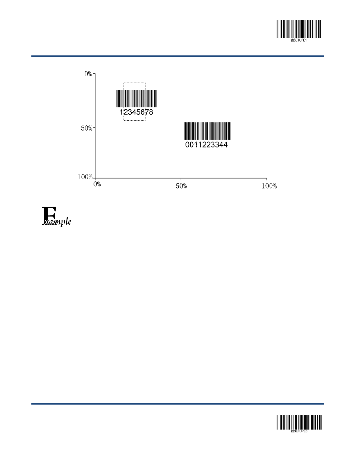
Enter Setup
Barcode 1
Barcode 2
Program the scanner to only read Barcode 1 in the figure above by setting the decoding area to
10% top, 45% bottom, 15% left and 30% right:
1. Scan the Enter Setup barcode.
2. Scan the Top of Dec odi ng Area barcode.
3. Scan the numeric barcode “0” from the “Digit Barcodes” section in A ppendix.
4. Scan the Save barcode from the “Save/Cancel Barcodes” section in Appendix.
5. Scan the Bottom of Decoding Area barcode.
6. Scan the numeric barcodes “4” and “5” from the “Digit Barcodes” sect i on in Appendix.
7. Scan the Save barcode from the “Save/Cancel Barcodes” section in Appendix.
8. Scan the Top of Dec odi ng Area barcode.
9. Scan the numeric barcodes “1” and “0” from the “Digit Barcodes” sect i on in Appendix.
10. Sc an the Save barc ode from the “Save/Cancel Barcodes” section in Appendix.
11. Sc an the Left of Decoding Area barcode.
12. Sc an the numeric barcode “0” from the “D igi t Barcodes” section in Appendix.
13. Scan the Save barc ode from the “Save/Cancel Barcodes” section in Appendix.
14. Sc an the Right of Decoding Area barcode.
15. Sc an the numeric barcodes “3” and “0” from the “Digit Barcodes” section in Appe ndix.
16. Sc an the Save barc ode from the “Save/Cancel Barcodes” section in Appendix.
17. Sc an the Left of Decoding Area barcode.
18. Sc an the numeric barcodes “1” and “5” from the “Digit Barcodes” section in Appe ndix.
19. Sc an the Save barc ode from the “Save/Cancel Barcodes” section in Appendix.
20. Sc an the Exit Setup barcode.
39
** Exit Setup
Page 56
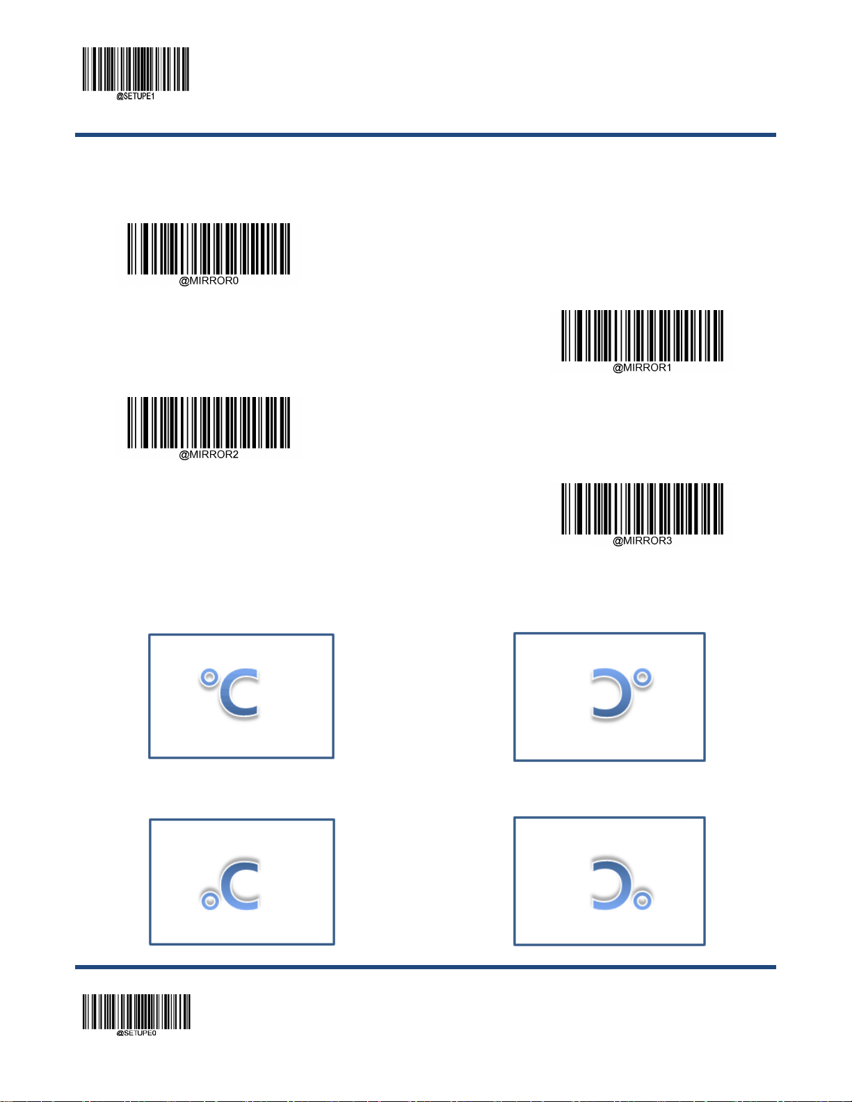
Enter Setup
Image Flipping
** Do Not Flip
Flip Vertically
Flip Horizontally
Flip Horizontally & Vertically
Example of image not flipped Example of image flipped horizontally
Example of image flipped vertically Example of image flipped horizontally & vertically
** Exit Setup 40
Page 57

Enter Setup
Bad Read Message
You may scan the appropriat e barcode below to sel ect whether or not t o send a bad read message (us er-programmable)
when a good read does not occur before tri gger release, or the decode session timeout expires.
** Bad Read Message OFF
Bad Read Message ON
Set Bad Read Message
A bad read message can contain up to 7 characters (HEX values from 0x00 to 0xFF). To set a bad read message, scan the
Set Bad Read Message barcode, the numeric barcodes represent ing th e hexa decimal valu es of des ired char act er(s) an d
the Save barcode. The default setting is “NG”.
Set Bad Read Message
Set the bad read message to “F” (HEX : 0x46):
1. Scan the Enter Setup barcode.
2. Scan the Set Bad Read Message barcode.
3. Scan the numeric barcodes “4” and “6” from the “Digit Barcodes” section in Appendix.
4. Scan the Save barcode from the “Save/Cancel Barcodes” section in Appendix.
5. Scan the Exit Setup barcode.
41
** Exit Setup
Page 58

Enter Setup
Power Off/Battery Off
Power Off Scanner
Battery Off
(For Long-term Storage/Shipping)
Note: After scanning the Battery Off bar code, you MUST insert the s canner in a po wered cradle to e xit batter y protectio n
mode before turning it on.
Default Settings
Factory Defaults
Scanning the Reset Scanner/Reset Cradle barcode can restore the scanner/cradle to the factory defaults.
You may need to reset your scanner/cradle when:
1. Scanner/cradle is not proper ly configured so that the scanner fails to decode barcodes or to communicate with the
cradle.
2. you forget previous configuration and want to avoid its impact.
3. functions that are rarely used have been enabled for the time being.
Reset Scanner
Reset Cradle
** Exit Setup 42
Page 59

Enter Setup
Custom Defaults
Scanning the Restore All Custom Defau lts barcode can reset all parameters to the custom def aults. Scann ing the Save
as Custom Defaults barcode can set the current settings as custom defaults.
Custom defaults are stored in the non-volatile memory.
Save as Custom Defaults
Restore All Custom Defaults
Restoring the scanner to the factory defaults will not remove the custom defaults from the scanner.
43
** Exit Setup
Page 60

Enter Setup
Query Scanner Information
After scanning the barcode belo w, the scanner information (including product name, firmware version, decoder version,
hardware version, product serial number, OEM serial number and manufacturing date) will be sent to the host device.
Query Scanner Information
Query Product Name
Query Firmware Version
Query Decoder Version
Query Product Name
Query Firmware Version
Query Decoder Version
** Exit Setup 44
Page 61

Query Data Formatter Version
Query Hardware Version
Enter Setup
Query Data Formatter Version
Query Hardware Version
Query Serial Number
Query Manufacturing Date
Query Serial Number
Query Manufacturing Date
45
** Exit Setup
Page 62

Enter Setup
Query OEM Serial Number
Query OEM Serial Number
Query Cradle Information
After scanning the barcode below, the cradle information (including model number, firmware version, hardware information,
product serial number, and manufact uring date) will be sent to the host dev i c e.
Query Model Number
Query Firmware Version
Query Cradle Information
Query Model Numer
Query Firmware Version
** Exit Setup 46
Page 63

Query Hardware Information
Query Serial Number
Enter Setup
Query Hardware Information
Query Serial Number
Query OEM Serial Number (ESN)
Query Manufacturing Date
Query OEM Serial Number
Query Manufacturing Date
47
** Exit Setup
Page 64

Enter Setup
Query Remaining Battery of Scanner
After scanning the barcode below, the percentage of battery power remaining will be sent to the host device.
Query Remaining Battery of Scanner
** Exit Setup 48
Page 65

Enter Setup
Chapter 4 Wireless Communications
Operating Modes
The scanner provides the following two operating modes:
Bluetooth HID Mode al lows your scanner to communicate with a remot e host using Bluetooth. You must f irst pair your
scanner to the host before these two Blueto oth devices can communicat e with each other. All featur es available for USB
HID Keyboard are applicable to Bluetooth HID.
Cradle Mode allows your scanner to communicate with a remote host by pairing with a cradle.
** Cradle Mode
Bluetooth HID Mode
Batch Mode
Batch Mode Options
Off: The scanner att empts to transm it every barc ode you scan. W hen you are out of service rang e, the scanned data will
be lost.
Automatic Batch Mod e: When in service range, the scanner attempts to transmit every barcode you s can. When out of
range, the scanner stores the scanned data i n the flash memory. Once you are back to service range, the scanner will
automatically transmit the stored data and then remove it from the f l as h memory after transmission is done.
Manual Batch Mode: Scanne d data will b e st ored in the f la sh memor y no m atter whether you ar e in ser vice ra nge or n ot.
You may send the stored data to the host in one of the following ways: (i) press the Batch but ton on the cradle after
inserting the scanner in cradle; (ii) scan the Transmit Stored Data barcode; or (iii) send the corresponding serial command
to the scanner. T he scanner will automatically remov e the stored d ata fro m the flash me mory after t ransmissi on is done if
the Auto Clear Stored Data after Transmission feature is turned on.
49
** Exit Setup
Page 66

Enter Setup
** Off
Automatic Batch Mode
Manual Batch Mode
Prevent Same Barcode Storage
This feature is available only when scanning barcodes in the Automatic or Manual Batch mode.
On: The scanner discards the data and generates an error beep when encountering a barcode that has existed in the flash
memory.
Off: The scanner stores the data when enc ountering a barcode that has existed in the flash memory.
** Off
On
** Exit Setup 50
Page 67

Enter Setup
Batch Mode Transmit Delay
Sometimes when multiple barcodes stor ed in the flash m emor y are sent to the host , the t ransm issi on of t hose barc odes is
too fast for the application to proc es s. To program a transmit delay betwee n bar codes, scan one of the following delays.
** No Transmit Delay (0ms)
Short Transmit Delay (50ms)
Medium Transmit Delay (100ms)
Custom Transmit Delay (0-10,000ms)
Set the batch mode transmit delay to 200 m s:
1. Scan the Enter Setup barcode.
2. Scan the Custom Transmit Delay barcode.
3. Scan the numeric barcodes “2”, “0” and “0” from the “Digit B arcodes” section in Appendix.
4. Scan the Save barcode from the “Save/Cancel Bar c odes” section in Appendix.
Long Transmit Delay (150ms)
51
5. Scan the Exit Setup barcode.
** Exit Setup
Page 68

Enter Setup
End of Transmission Message for Batch Mode
You may scan the appropriate barcode below to select whether or not to send an end of transmission message
(user-programmable) to notify the host when transmission of all stored data is done.
** End of Transmission Message Off
End of Transmission Message On
An end of transmission message ca n contain up to 10 characters (HEX values from 0x00 to 0xFF). T o set an end of
transmission message, scan the Set End of T ransmission Message barcode, the n umeric barcodes representing the
hexadecimal values of desired c haracter(s) and the Save barcode. The default setting is “EOT”.
Set End of Transmission Message
Set the end of transmission message t o “END” (HEX: 0x45, 0x4E, 0x44):
1. Scan the Enter Setup barcode.
2. Scan the Set End of Transmission Message barcode.
3. Scan the numeric barcodes “4”, “5”, “4”, “E”, “4” and “4” from the “Digit Barcodes” section in
Appendix.
4. Scan the Save barcode from the “Save/Cancel Barcodes” section in Appendix.
5. Scan the Exit Setup barcode.
** Exit Setup 52
Page 69

Enter Setup
Transmit Stored Data
You may scan the barcode below to send the stored data in the flash memory to the hos t.
Transmit Stored Data
Auto Clear Stored Data after Transmission
You may scan the appropriate barcode below to choose whether to clear or keep the stored data in the flash memory after
transmission This feature is only available to the Manual Batch mode.
** Off
Query/Clear Stor ed Data in Flash
Query the Number of Stored Barcodes
On
Clear All Stored Data
53
** Exit Setup
Page 70

Enter Setup
Retransmission
If the Transmission feature is on, the scanner awaits an ACK response from the host following a data packet transmission,
and resends the packet when it receives an NAK res ponse or the retransmis sion timeout expir es. Note that Data Pac king
must be enabled for this feature to funct ion (See the “Data Packing Options” in C haper 9 to learn how to enable it).
** Retransmission Off
Retransmission On
Transmission Timeout
This specifies the amount of time the scanner waits for an ACK response from the host following a data packet
transmission. It is programmable in 1ms i ncrements from 200ms to 10,00 0ms. The default value is 200ms . Note that the
Retransmission feature must be turned on for this to function.
Set Transmission Timeout
Set the transmission timeout to 300ms:
1. Scan the Enter Setup barcode.
2. Scan the Set Transmission Timeout barcode.
3. Scan the numeric barcodes “3”, “0” and “0” from the “Digit Barcodes” section in Appendix.
4. Scan the Save barcode from the “Save/Cancel B arcodes” section in Appendix.
5. Scan the Exit Setup barcode.
** Exit Setup 54
Page 71

Enter Setup
Retransmission Count
This parameter specifies the number of times the scanner resends a data packet when it awaits an ACK response from the
host. The selection range is from 1 to 10 retransmissions. The default value is 3 (retransmissions). Note that the
Retransmission feature must be turned on for this to function.
Set Retransmission Count
Set the retransmission count t o 5:
1. Scan the Enter Setup barcode.
2. Scan the Set Retransmission Timeout barcode.
3. Scan the numeric barcodes “3”, “0” and “0” from the “Digit Barcodes” section in Appendix.
4. Scan the Save barcode from the “Save/Cancel Barcodes” section in Appendix.
5. Scan the Exit Setup barcode.
55
** Exit Setup
Page 72

Enter Setup
Scanner(s) to Cradle Support
Wireless Communication Modes
Point-to-Point Mode: Only one scanner can be paired to one cradle at a time.
Multiple-to-Point Mode: Up to seven scanners can be paired to one cradle.
** Point-to-Point Mode
Multiple-to-Point Mode
Clear Pairing Info on Scanner/Cradle
Clear Pairing Info on Cradle
Clear Pairing Info on Scanner
** Exit Setup 56
Page 73

Enter Setup
Set Date and Time
You may use the following command to set the date and time on your scanner:
WLSTIMyyyymmddhhmmss (yyyy: The desired year; mm: The desired month; dd: The desired day; mm: The desired
month; ddmmss: The desired time)
Example: Set the date to February 5
Enter: ~<SOH>0000@WLSTIM20180205103011;<ETX>
th
2018 and time to 10:30:11
Query Current Date and Time
After scanning the barcode below, the current date and time in YYYYMMDDHHMMSS format will be sent to the host device.
For example, query result “20180205103011” means February 5
Query Current Date and Time
th
2018 10:30:11.
Time Stamp
You can select whether or not to send date & time before each sc anned data by scanning the appropriate barcode below.
** Do Not Send Time Stamp
Send Time Stamp
57
** Exit Setup
Page 74

Enter Setup
Set Time Stamp Format
** Format 1: (YYYY/MM/DD,HH:MM:SS)
(example: 2018/01/23,10:30:20)
Format 3: (MM/DD/YYYY,HH:MM:SS)
(example: 01/23/2018,10:30:20)
Format 2: (DD/MM/YYYY,HH:MM:SS)
(example: 23/01/2018,10:30:20)
** Exit Setup 58
Page 75

Enter Setup
Chapter 5 RS-232 Interface
Introduction
When the cradle is connected to the RS-232 port of a host device, you need t o set communication parameters ( including
baud rate, parity check, data bit and stop bit) on the cradl e to match the host device so that t wo devices can comm unic ate
with each other.
Baud Rate
Baud rate is the number of bits of data transmitted per second. Set the baud rat e to match the host requirements.
115200
38400
14400
57600
19200
** 9600
59
** Exit Setup
Page 76

Enter Setup
4800
1200
Parity Check
Set the parity type to match the host requirements.
2400
Odd Parity: If the data contains an odd number of 1 bits, the parity bit value is set to 0.
Even Parity: If the data contains an even number of 1 bits, the parity bit value is set to 0.
None: Select this option when no parity bit i s required.
** None
Odd Parity
Even Parity
** Exit Setup 60
Page 77

Data Bit
Set the number of data bits to match the host requirements.
7 Data Bits
Enter Setup
** 8 Data Bits
Stop Bit
The stop bit(s) at the end of each transmitted charac ter marks the end of transmi ssion of one character and prepares the
receiving device for the next character in the serial data stream. Set the number of stop bits to match the host
requirements.
** 1 Stop Bit
2 Stop Bits
61
** Exit Setup
Page 78

Enter Setup
Hardware Auto Flow Control
If CTS flow control is enabled, the cradle determines whether to transmit data based on CTS signal level. When CTS signal
is at low level which means the serial port’s cache memory of receiving device (such as PC) is full, the cradle stops sending
data through serial port unt il CT S signal i s s et to high lev el by rec eivi ng device. If RTS flow control is enabled, wheth er t he
cradle receives data or not is dependent on RTS signal level. If the cradle is not ready for receiving, it will set RTS signal to
low level. When sending device (such as PC) detects it, it will not se nd data to the cradle any more to prevent data loss.
If No Flow Control is selected, reception/transmission of serial data will not be influenced by RTS/CTS signal.
** No Flow Control
RTS Flow Control
CTS Flow Control
CTS/RTS Flow Control
Before enabling this feature, make sure that RTS/CTS signal lines are contained in RS-232 cable.
Without the signal lines, RS-232 communication errors will occur.
** Exit Setup 62
Page 79

Enter Setup
Chapter 6 USB Interface
Introduction
There are four options for USB connection between the cradle and host device:
USB HID Keyboard: The cradle’s transmission is simulated as USB keyboard input with no need for command
configuration or a driver. Barc ode data could be enter ed by the virtual k eyboard direct ly and it is also conve nient for
the host device to receive data.
USB CDC: It is compliant with the standard USB CDC clas s specif icat io ns def ined by th e U SB-I F and all o ws the host
device to receive data in the way as a seri al port does. A driver is needed when using this feature.
HID POS (POS HID Barcode Scanner): It is based on the HID interf ace, with no need for a custom driver. It excels
virtual keyboard and traditional RS-232 interface in transmission speed.
IBM SurePOS: It conforms to IBM (now Toshiba Global Commerce Solutions) 4698 USB scanner interface
specifications.
When the cradle is connected to both USB and RS-232 ports on a host device, it will select the USB connection by default.
63
** Exit Setup
Page 80

Enter Setup
USB HID Keyboard
When the cradle is connected to the USB port on a host device, you can enable the USB HID Keyboard feature by
scanning the barcode below. The cradle’s transmission will be simulated as USB keyboard input. The Host receives
keystrokes onthe virtual keyboard. It works on a Plug and Play basis and no driver is required.
** USB HID Keyboard
If the host device allows keyboard i nput, then no extra software is needed for HID Keyboard input.
** Exit Setup 64
Page 81

USB Country Keyboard Types
Keyboard layouts vary from country to country. The default setting is U .S. keyboard.
** U.S. (English)
Brazil
Enter Setup
Belgium
Canada (French)
Czechoslovakia
Denmark
Finland (Swedish)
65
** Exit Setup
Page 82

Enter Setup
France
Germany/ Austria
Greece
Hungary
Israel (Hebrew)
Italy
Latin America/ South America
Netherlands (Dutch)
** Exit Setup 66
Page 83

Enter Setup
Norway
Poland
Portugal
Romania
Russia
Slovakia
Spain
Sweden
67
** Exit Setup
Page 84

Enter Setup
Switzerland (German)
Turkey_F
Turkey_Q
UK
Japan
** Exit Setup 68
Page 85

Enter Setup
Emulate ALT+Keypad
When Emulate ALT+Keypad is turned on, any character whose ASCII value is greater than or equal to 0x20 is sent over
the numeric keypad no matter which k eyboard type is selected.
1. ALT Make
2. Enter the number corresponding to a desired character on the keypad.
3. ALT Break
After Emulate ALT+Keyp ad ON is selected, you need to choose the code page with which the barcodes were created and
to turn Unicode Encoding On or Off depending on the encoding used by the application software.
** Emulate ALT+Keypad OFF
Emulate ALT+Keypad ON
Since sending a character involves multipl e keystroke emulations, this method appears less efficient.
Supposing Emulate ALT+Keypad is ON, Unicode Encoding is Off, Code Page 1252 (West Europ ean
Latin) is selected, and Emulate Keypad with Leading Zero is Off, barcode data ”AÐF” (65/208/70) is
sent as below:
“A” – “ALT Make” + “065” + “ALT Break”
“Д -- “ALT Make” + “208” + “ALT Break”
“F” -- “ALT Make” + “070” + “ALT Break”
69
** Exit Setup
Page 86

Enter Setup
Code Page
Code pages define the mapping of character codes to characters. If the data received does not display with the proper
characters, it may be because the barcode being scanned was created using a code page that is different from the one the
host program is expecting. If this is the case, select the code page with which the barcod es were created b y scanning the
appropriate barcode below. For PDF417, QR Code, Aztec and Dat a Matrix, besi des setti ng the code page, you also need
to set the character encoding in the “Character Encoding” section in Chapter 7. This feature is only effective when Emulate
ALT+Keypad is turned on.
** Code Page 1252 (West European Latin)
Code Page 1250 (Central and East European Latin)
Code Page 1254 (Turkish)
Code Page 1251 (Cyrillic)
Code Page 1253 (Greek)
Code Page 1255 (Hebrew)
** Exit Setup 70
Page 87

Enter Setup
Code Page 1256 (Arabic)
Code Page 1257 (Baltic)
Code Page 1258 (Vietnamese)
Code Page 950 (Traditional Chinese, Big5)
Code Page 932 (Japanese, Shift-JIS)
Code Page 936 (Simplified Chinese, GB2312, GBK)
Code Page 874 (Thai)
71
** Exit Setup
Page 88

Enter Setup
Unicode Encoding
Different host program may use different charact er encodin gs for handl ing incom ing barco de data. For instance, Micros oft
Office Word uses Unicode encodi ng and therefore you should turn Unicode Encoding on, whereas Microsoft O ffice Excel
or Notepad uses Code Page enc oding an d therefor e you should tur n Unicode Encoding off. This feature is onl y effect ive
when Emulate ALT+Keypad is turned on.
** Off
On
Emulate Keypad with Leading Zero
You may turn this feature on to sen d character s equences s ent over the n umeric keypa d as ISO c haracters which have a
leading zero. For example, ASCII A transmits as “ALT MAKE” 0065 “ALT BREAK”. This feature is only effective when
Emulate ALT+Keypad is enabled.
** On
Off
** Exit Setup 72
Page 89

Function Key Mapping
When Ctrl+ASCII Mode is selected, function characters (0x00 - 0x1F) are sent as ASCII sequences.
** Disable
Ctrl+ASCII Mode
Alt+Keypad Mode
If Ctrl+ASCII Mode is selected and other parameters of USB HID Keyboard adopt factory defaults,
barcode data “A<HT>(i.e. Horizontal Tab)F” (0x41/0x09/0x46) is sent as bel ow:
Enter Setup
73
“A” - Keystroke “A”.
<HT> - “Ctrl Make” + Keystroke “I” + “Ctrl Break”
“F” - Keystroke “F”
For some text editors, “Ctrl I” means i talic convert. So the output ma y be “AF”.
If Alt+Keypad Mode is selected and other parameters of USB HID Ke ybo ard a do pt f act o r y defau lts , t he
data above is sent as below:
“A” - Keystroke “A”.
<HT> - “Alt Make” + Keystrokes “009” + “Alt Break”
“F” - Keystroke “F”
** Exit Setup
Page 90

ASCII Function
ASCII Value (HEX)
Function Key Mapping Disabled
Ctrl+ASCII
NUL
00
Null
Ctrl+@
STX
02
Caps Lock
Ctrl+B
ETX
03
ALT
Ctrl+C
EOT
04
Null
Ctrl+D
ENQ
05
CTRL
Ctrl+E
ACK
06
Null
Ctrl+F
VT
0B
Vertical Tab
Ctrl+K
FF
0C
Delete
Ctrl+L
CR
0D
Enter
Ctrl+M
DC1
11
Home
Ctrl+Q
DC2
12
PrintScreen
Ctrl+R
DC3
13
Backspace
Ctrl+S
DC4
14
tab+shift
Ctrl+T
CAN
18
F3
Ctrl+X
EM
19
F4
Ctrl+Y
SUB
1A
F5
Ctrl+Z
US
1F
F10
Ctrl+-
Enter Setup
ASCII Function Key Mapping Table
SOH 01 Keypad Enter Ctrl+A
BEL 07 Enter Ctrl+G
BS 08 Left Arrow Ctrl+H
HT 09 Horizontal Tab Ctrl+I
LF 0A Down Arrow Ctrl+J
SO 0E Insert Ctrl+N
SI 0F Esc Ctrl+O
DLE 10 F11 Ctrl+P
NAK 15 F12 Ctrl+U
SYN 16 F1 Ctrl+V
ETB 17 F2 Ctrl+W
ESC 11 F6 Ctrl+[
FS 1C F7 Ctrl+\
GS 1D F8 Ctrl+]
RS 1E F9 Ctrl+6
** Exit Setup 74
Page 91

Enter Setup
ASCII Function Key Mapping Table (Continued)
The last five characters (0x1B~0x1F) in the table above apply to US keyboard layout only. The following chart provides the
equivalents of these five characters f or other countries.
Country Ctrl+ASCII
United States Ctrl+[ Ctrl+\ Ctrl+] Ctrl+6 Ctrl+-
Belgium Ctrl+[ Ctrl+< Ctrl+] Ctrl+6 Ctrl+-
Scandinavia Ctrl+8 Ctrl+< Ctrl+9 Ctrl+6 Ctrl+-
France
Germany Ctrl+Ã Ctrl++ Ctrl+6 Ctrl+-
Italy Ctrl+\ Ctrl++ Ctrl+6 Ctrl+-
Switzerland
United Kingdom Ctrl+[
Denmark Ctrl+8 Ctrl+\ Ctrl+9 Ctrl+6 Ctrl+-
Norway
Spain Ctrl+[ Ctrl+\ Ctrl+] Ctrl+6 Ctrl+-
Ctrl+^ Ctrl+8 Ctrl+$ Ctrl+6 Ctrl+=
Ctrl+< Ctrl+.. Ctrl+6 Ctrl+-
Ctrl+¢
Ctrl+8 Ctrl+\ Ctrl+9 Ctrl+6 Ctrl+-
Ctrl+] Ctrl+6 Ctrl+-
75
** Exit Setup
Page 92

Enter Setup
Inter-Keystroke Delay
This parameter specifies the delay between emulated keystrokes.
** No Delay
Short Delay (20ms)
Long Delay (40ms)
** Exit Setup 76
Page 93

Convert Case
You may scan the appropriate barcode below to convert all bar code data to your des i red case.
** No Case Conversion
Convert All to Upper Case
Convert All to Lower Case
When the Convert All to Lower Case feature is enabled, barcode data “AbC” is transmitted as “abc”.
If Emulate ALT+Keypad ON is selected, Convert All to Lower Case and Convert All to Upper Case
do not function.
Enter Setup
77
** Exit Setup
Page 94

Enter Setup
Emulate Numeric Keypad
Do Not Emulate Numeric Keypad 1: Sending a number (0-9) is emulated as keystroke(s) on main keyboard.
Emulate Numeric Keypad 1: Sending a number (0-9) is emulated as keystroke(s) on numeric keypad. The state of Num
Lock on the simulated numeric keypad is determined by its equivalent on the host device. If Num Lock on the host device is
turned off, the output of simulated numeric keypad is function key instead of number.
Do Not Emulate Numeric Keypad 2: Sending “+”, “-”, “*” and “/” is emulated as keystroke(s) on main keyboard.
Emulate Numeric Keypad 2: Sending “+” , “-”, “*” and “/” is emulated as keystroke(s) on numeric keypad.
** Do Not Emulate Numeric Keypad 1
Emulate Numeric Keypad 1
** Exit Setup 78
Page 95

** Do Not Emulate Numeric Keypad 2
Enter Setup
Emulate Numeric Keypad 2
Emulate ALT+Keypad ON prevails over Emulate Numeric Keypad.
Supposing the Emulate Numeric Keypad 1 feature is enabled:
if Num Lock on the host device is ON, “A4.5” is transmitted as “A4.5”;
if Num Lock on the host device is OFF, “A4.5” is transmitted as “.A”:
1. “A” is sent on main keyboard;
2. “4” is sent as the function key “Cursor Move to Left”;
3. “.” is sent on main keyboard;
4. “5” is not sent as it does not correspon d to any function key.
79
** Exit Setup
Page 96

Enter Setup
Polling Rate
This parameter specifies the polling rate for a USB keyboard. If the Host drops charact ers, change the polling rate to a
bigger value.
1ms
2ms
3ms
5ms
7ms
** 4ms
6ms
** Exit Setup 80
Page 97

Enter Setup
8ms
9ms
10ms
81
** Exit Setup
Page 98

Enter Setup
USB CDC
If your cradle is connected to the USB port on a host device, the USB CDC feature allows the host device to receive data in
the way as a serial port does. A driver is needed when using this feature. You may download it from our website at
www.newlandaidc.com.
** USB CDC
** Exit Setup 82
Page 99

Enter Setup
HID POS (POS HID Barcode Scanner)
Introduction
The HID-POS interface is recom mended for new application program s. It can send up to 56 characters in a single USB
report and appears more efficient than keyboard emulation.
Features:
1. HID based, no custom driver required.
2. Way more efficient in communication than keyboard emulation and tradi tional RS-232 interface.
USB HID-POS
Access the Cradle with Your Program
Use CreateFile to access the cradle as a HI D device and then us e Read File to deliv er the scan ned data t o the applicat ion
program. Use WriteFile to send data to the cradle.
For detailed information about U S B and H ID interfaces, go to
www.USB.org.
83
** Exit Setup
Page 100

Enter Setup
Acquire Scanned Data
After a barcode is decoded, the cradl e s ends an input report as below:
Byte 7 6 5 4 3 2 1 0
0 Report ID = 0x02
1 Barcode Length
2-57 Decoded Data (1-56)
58-61 Reserved
62 Newland Symbology Identifier or N/C: 0x00
63
- - - - - - -
Bit
Send Command to the Cradle
This output report is used to send comm ands to the cradle. All programming commands can be used.
Bit
Byte 7 6 5 4 3 2 1 0
Decoded data
continued
0 Report ID = 0x04
1 Length of command
2-63 Command (1-62)
** Exit Setup 84
 Loading...