

Page 1
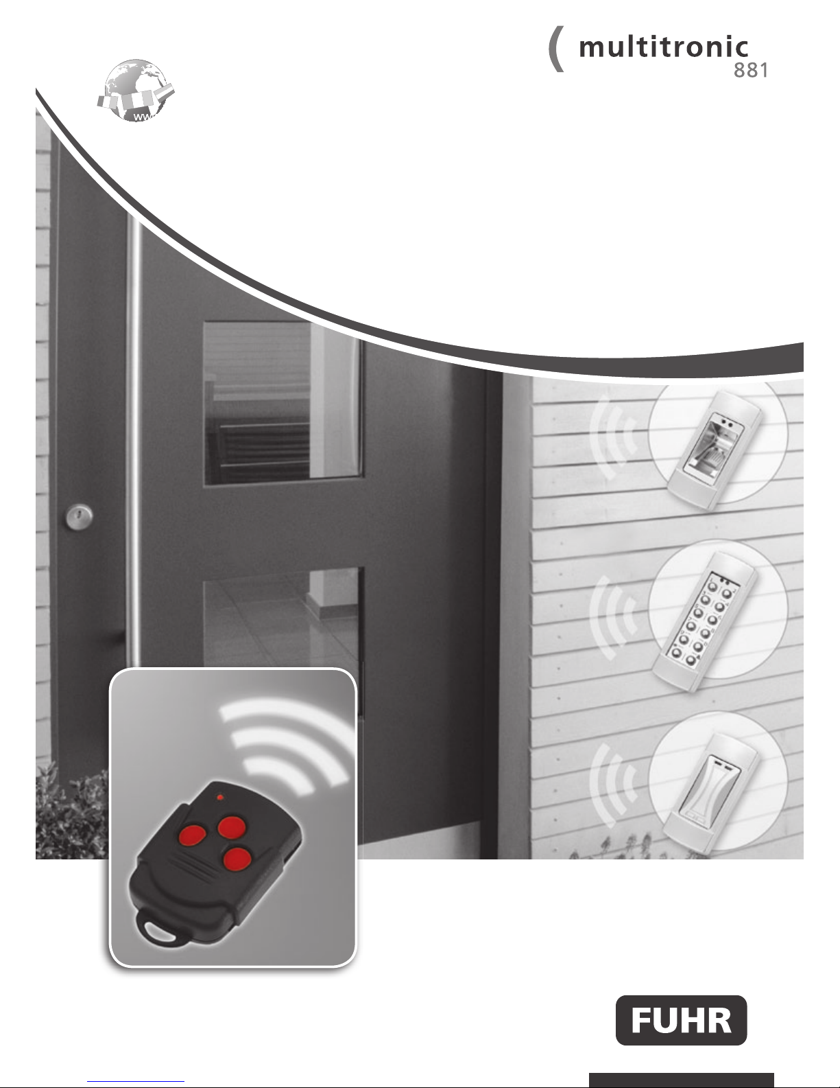
Installation, operation and
maintenance instructions
These instructions are
to be passed on by the
fitter to the use
MBW20-GB/07.11-17
WWW.FUHR.DE
www.fuhr.dewww.fuhr.de
Page 2
2
WWW.FUHR.DE
1 Introduction 3
2 Important information/safety instructions 4
3 Delivery scope 5
4 Installation instructions 7
4.1 Routing and drilling operations 7
4.1.1 Cable-laying depending on the door design 8
4.1.2 Routing for the electronic drive unit in the door leaf 8
4.1.3 Routing for the tappet contacts in the door leaf 9
4.1.4 Routing for the control unit casing in the door frame 9
4.1.5 Routing for the switching power supply unit in the door frame 10
4.1.6 Drilling for the surface-contact device’s cable 10
4.1.7 Drilling for the 230 V power supply cable 11
4.1.8 Safety instructions 11
4.1.9 Screws for fixing individual components 11
4.2 Installation 12
4.2.1 Installation of the tappet contacts in the door leaf 13
4.2.2 Installation of the multipoint locking system in the door leaf 14
4.2.3 Installation of the cable guides, end caps and cover plates in the door leaf 15
4.2.4 Installation of the magnetic contact in the door frame 16
4.2.5 Installation of the surface-contact device in the door frame 16
4.2.6 Installation of the control unit casing in the door frame 17
4.2.7 Installation of the switching power supply unit (transformer) in the door frame 18
5 Commissioning 19
5.1 Fabricator’s function check 19
5.2 Commissioning on site 19
5.3 The radio keys (radio-controlled remote control) 20
5.4 Master radio key 20
5.5 Tuning in and deleting radio keys 21
5.5.1 Tuning in individual radio keys (max. 25) 21
5.5.2 Deleting individual radio keys (except the master key) 22
5.5.3 Deleting all radio keys (except the master key) 23
6 External connection options 24
6.1 Control unit casing circuit board 24
6.1.1 Application examples for circuit board assignment 26
6.2 The drive unit’s multi-functional jack 27
7 Maintenance and care 28
7.1 Contact device 29
8 Troubleshooting 30
8.1 Adjustment of strike plates/one-piece strike plates and latch changing 31
9 Technical data 32
9.1 FUHR multitronic radio key (remote control) 32
9.2 FUHR multitronic control unit with radio receiver 32
9.3 FUHR multitronic drive unit 32
9.4 FUHR multitronic switching power supply unit 33
10 Optional accessories 34
11 Wiring diagram 36
Contents
www.fuhr.dewww.fuhr.de
Instructions in further languages, refer to www.fuhr.de
Page 3
3
The FUHR multipoint locking system multitronic 881 locks doors electromotively – at all times and fully automated.
•Particularly reliable – strong and fast – due to two parallel high performance drives.
•This conserves energy as the door always closes imperviously.
•Enables secure locking of main entrance doors, apartment doors or back doors.
•Suitable for use with all door materials.
•All locking components can be operated either electromotively via a radio key, mechanically via the profile cylinder’s key, or
from the inside via the door lever handle.
•The electricity and data transfer is carried out from the door frame to the door leaf via a wireless transmission device. Springloaded contact pins enable the door leaf to be unhinged for e.g. for decorating purposes at any time.
The standard locking and unlocking functions in detail:
Special functions are described in chapter 6.
Locking (closing):
All locking components are locked automatically 3 sec. after the door has been closed over. (This can however in
emergency situations - e.g. in the event of power failure - also be carried out mechanically by turning the key 4 times.)
Unlocking (opening) from the outside:
•By means of the radio key provided
•Alternatively by using the free-running profile cylinder’s key (depending on the drive-gear position; 4 turns!)
•Optionally by means of another access system e.g. transponder, code lock, finger print recognition, eye scanner or similar
(release signal via potential-free contact!)
Unlocking (opening) from the inside:
•Via the door lever handle as usual
•Alternatively by using the free-running profile cylinder’s key (depending on the drive-gear position; 4 turns!)
•Alternatively by means of the radio key provided
•Optionally via a domestic intercom system (6-12 V AC!)
•Optionally via a wireless wall-mounted push-button switch
•Optionally by means of another access system e.g. transponder, code lock, finger print recognition, eye scanner or similar
(release signal via potential-free contact!)
•As well as access control systems pertaining to contemporary BMS devices (Building Management Systems) (24 V DC processor impulse!)
The locked mode is indicated by two brief acoustic signals. Simultaneously a red LED located on the control unit on the internal
side of the door indicates the locked mode. A green LED indicates the unlocked mode.
Do not operate the lever-handle during the electrical locking and unlocking procedure!
Further electrical connections are available for:
•Alarm systems
•Access control systems (fingerprint scanner, code lock, transponder etc.)
•Illuminated fixed pad handles/glazed units
•Electrically operated door openers (e.g. for disabled accessible doors = ‘barrier-free building’)
1 Introduction
1 INTRODUCTION
2 IMPORTANT
INFORMATION
3 DELIVERY SCOPE
8 TROUBLE-
SHOOTING
4 INSTALLATION
INSTRUCTIONS
5 COMMISSIONING
6 EXTERNAL
CONNECTION
OPTIONS
7 MAINTENANCE
AND CARE
9 TECHNICAL
DATA
10 OPTIONAL
ACCESSORIES
Page 4

4
WWW.FUHR.DE
These instructions are aimed at door fabricators and contain important information regarding installation, commissioning and
operation pertaining to the FUHR multipoint locking system multitronic 881. Please read carefully prior to installation and commissioning. The points raised here provide supplementary information to the FUHR product information M3/3. The importance of
their compliance must be pointed out to builders and end-users. In the event of non-compliance with these imperative instructions,
faultless system operation cannot be warranted.
We assume that the installation as well as commissioning is carried out exclusively by professional staff.
Text passage denoting this symbol
is relevant to safety and must be strictly adhered to.
The FUHR multipoint locking system multitronic 881 has been designed and manufactured taking safety-related regulations and
harmonised standards into account.
The safety of the FUHR multitronic product largely depends on its correct installation and regular
maintenance! The installation of the electronic components requires particular care, since abrasion points,
defective cables, damaged contacts, etc. affect security and can lead to the malfunction of the system. Please
ensure that all components are in perfect functioning condition prior to installation. Damaged or defective
components may not be used under any circumstances. Use the locking system only in technically
perfect condition! Malfunctions that impair security are to be eliminated immediately. Until the
malfunction has been eliminated, the drive unit is to be switched off and operated mechanically! The power
supply unit’s power feed is to be disconnected when working on the locking system and live components.
The FUHR multipoint locking system multitronic 881 has been engineered to be used in conjunction with the provided FUHR
multitronic components. We accept no liability for improperly installed systems and/or the use of non-original or non factory
approved system accessory parts. The modification of components or the use of non approved accessory components can cause
malfunctions. Material damage or personal injury resulting from non-compliance with the installation, operation and maintenance
instructions or inappropriate operation invalidates the warranty. We assume no liability for any consequential damage.
The FUHR multipoint locking system multitronic 881 must be protected from humidity. It is not suitable for areas with high humidity
and chemical substances.
The FUHR multipoint locking system multitronic 881 has been primarily designed for installation in main entrance doors,
apartment doors and back doors. The system with 2 hook bolts (type 3) has been tested and certified in accordance with
DIN EN 179. The variants with 2 round bolts (type 8) and with 2 hook and dual round bolts (type 11) have been tested and
certified in accordance with DIN EN 1125. For this purpose durability testing in the highest grade (grade 7) with 200,000
operations was carried out successfully.
When using in heavily frequented doors (more than 50 operations per day) e.g. in public or office building projects, it is necessary to use either of the two day-latch functions during busy periods (refer chapter 6.1).
All images, dimensions, product and design related information contained in these instructions represent the latest
developments regarding the FUHR multipoint locking system multitronic 881 at the time of printing. This product is subject to a CIP
(continuous improvement process) and is constantly enhanced to reflect the latest technology. For the purpose of your satisfaction,
we reserve the right to implement changes to this product. Model and product claims cannot be lodged.
The latest version of these instructions is published on our website www.fuhr.de.
The installation steps depicted on the following pages serve as a schematic diagram. Due to the numerous profiles available on the
market, there may be slight deviations in specific points. It is therefore imperative that the profile-related routing drawing provided
with the FUHR multitronic set is adhered to. Please contact your sales partner or the manufacturer in the event of discrepancies or
queries.
The indicated sequence in these installation instructions is exemplary. The sequence may be varied if required.
IMPORTANT!
All components contained in the set (particularly the control unit and the radio key) are coordinated and should not be
used in conjunction with other sets.
2 Important information/safety instructions
Page 5
5
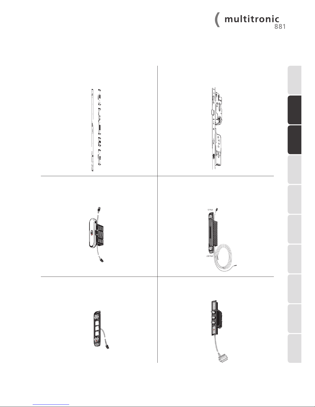
One-piece keep or individual keeps
Profile related version,
incl. magnetic contact
Multipoint locking system multitronic 881
incl. electromotive drive unit
Control unit with radio receiver and visual locking
indicator
Preassembled cable connectors (length 200 and 300 mm)
Switching power supply unit (transformer)
Profile related version,
230 V AC input/12 V DC output, Cable connectors 230 V
(length 3000 mm - surface- mounted cable), earth/ground
cable (length 400 mm) and 12 V (length 200 mm)
preassembled
Surface-contact device for electricity and data transfer
Preassembled cable connector (length 250 mm)
Tappet contacts for electricity and data transfer
Cable connector (length 4000 mm), with preassembled
multi-functional jack
3 Delivery scope
1 INTRODUCTION
2 IMPORTANT
INFORMATION
3 DELIVERY SCOPE
8 TROUBLE-
SHOOTING
4 INSTALLATION
INSTRUCTIONS
5 COMMISSIONING
6 EXTERNAL
CONNECTION
OPTIONS
7 MAINTENANCE
AND CARE
9 TECHNICAL
DATA
10 OPTIONAL
ACCESSORIES
Page 6
6
WWW.FUHR.DE
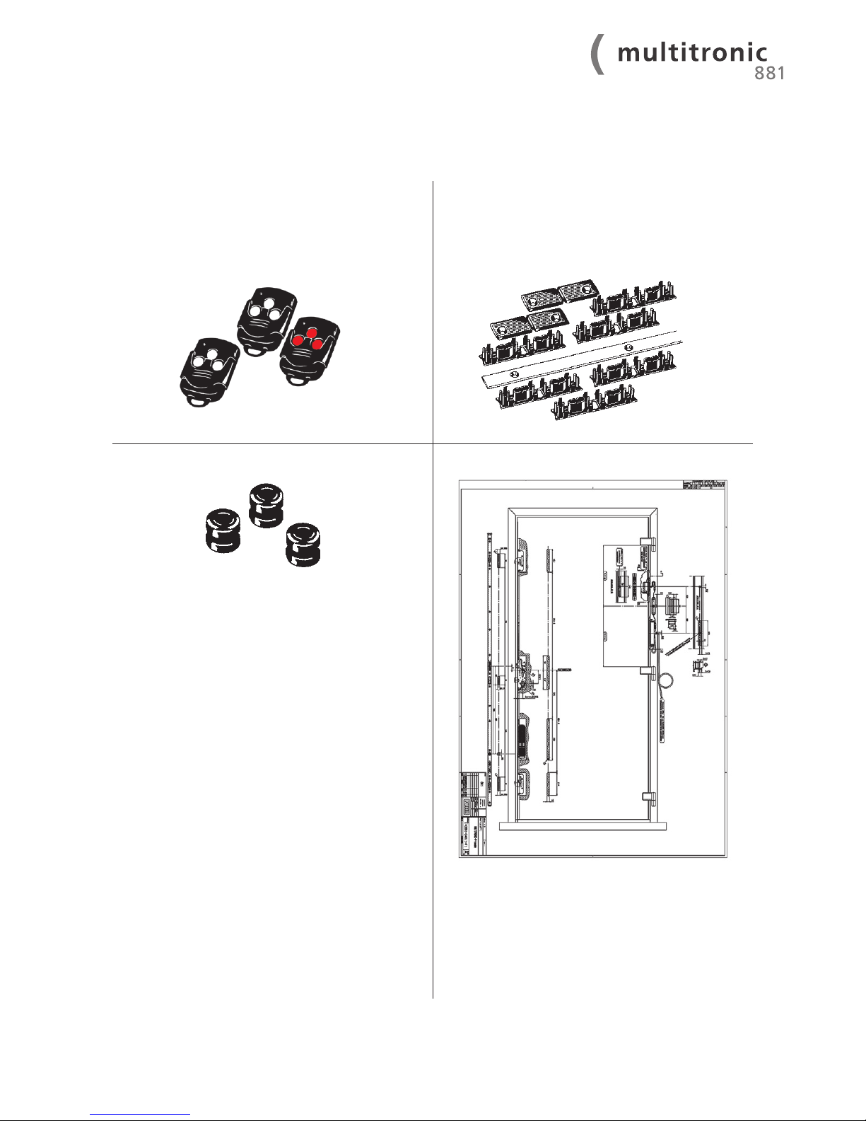
Radio key
to be handed over to the end user;
3-channel radio key as remote control,
1 pc. with red buttons = master key
2 pcs. with turquoise buttons
Cover plate, cable guides and end caps
for safe cable-laying (only for doors with Euro groove);
2 m. cover plate
6 pcs. double cable guides
2 pcs. end caps
Cable protection sleeves
3 pcs.
Profile-related routing drawing
Page 7
7
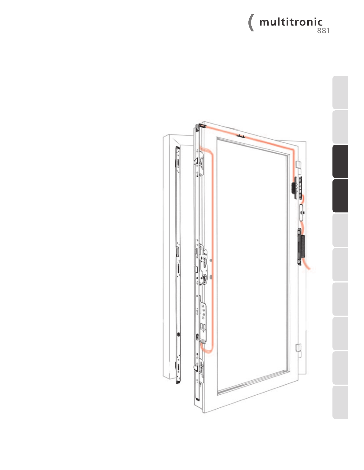
The routings for the FUHR multipoint locking system multitronic 881 are carried out in accordance with the routing drawing
provided.
In addition to the conventional routings
for FUHR multipoint locking systems, for example on multisafe 855,
only 2 additional routings in the door
leaf and the door frame are required.
These installation instructions therefore only describe the additional routing
and drilling operations for the electronic
locking mechanism.
4 Installation instructions
4.1 Routing and drilling operations
1 INTRODUCTION
2 IMPORTANT
INFORMATION
3 DELIVERY SCOPE
8 TROUBLE-
SHOOTING
4 INSTALLATION
INSTRUCTIONS
5 COMMISSIONING
6 EXTERNAL
CONNECTION
OPTIONS
7 MAINTENANCE
AND CARE
9 TECHNICAL
DATA
10 OPTIONAL
ACCESSORIES
Page 8
8
WWW.FUHR.DE
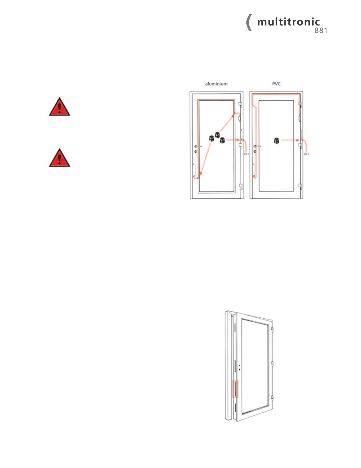
Version A – e.g. for PVC doors:
Cable-laying in the Euro groove.
Deburr the cable feedthrough hole
and insert the cable protection sleeves
provided.
Version B – e.g. for aluminium doors:
If the cable is to be laid in the glazing rebate’s Euro groove, a
Ø 10 mm drill hole is to be drilled in the glazing rebate area.
Deburr the cable feedthrough hole
and insert the cable protection sleeve
provided.
The 230 V electricity cable is a surface-mounted cable.
Conduit must be used for concealed cabling. The door
frame must be earthed/grounded.
The cable-laying for version A is described in the
following installation steps.
Routing in compliance with the separate routing drawing
between the main lock and the bottom additional locking
point
4.1.1 Cable-laying depending on the door design
4.1.2 Routing for the electronic drive unit in the door leaf
Page 9
9
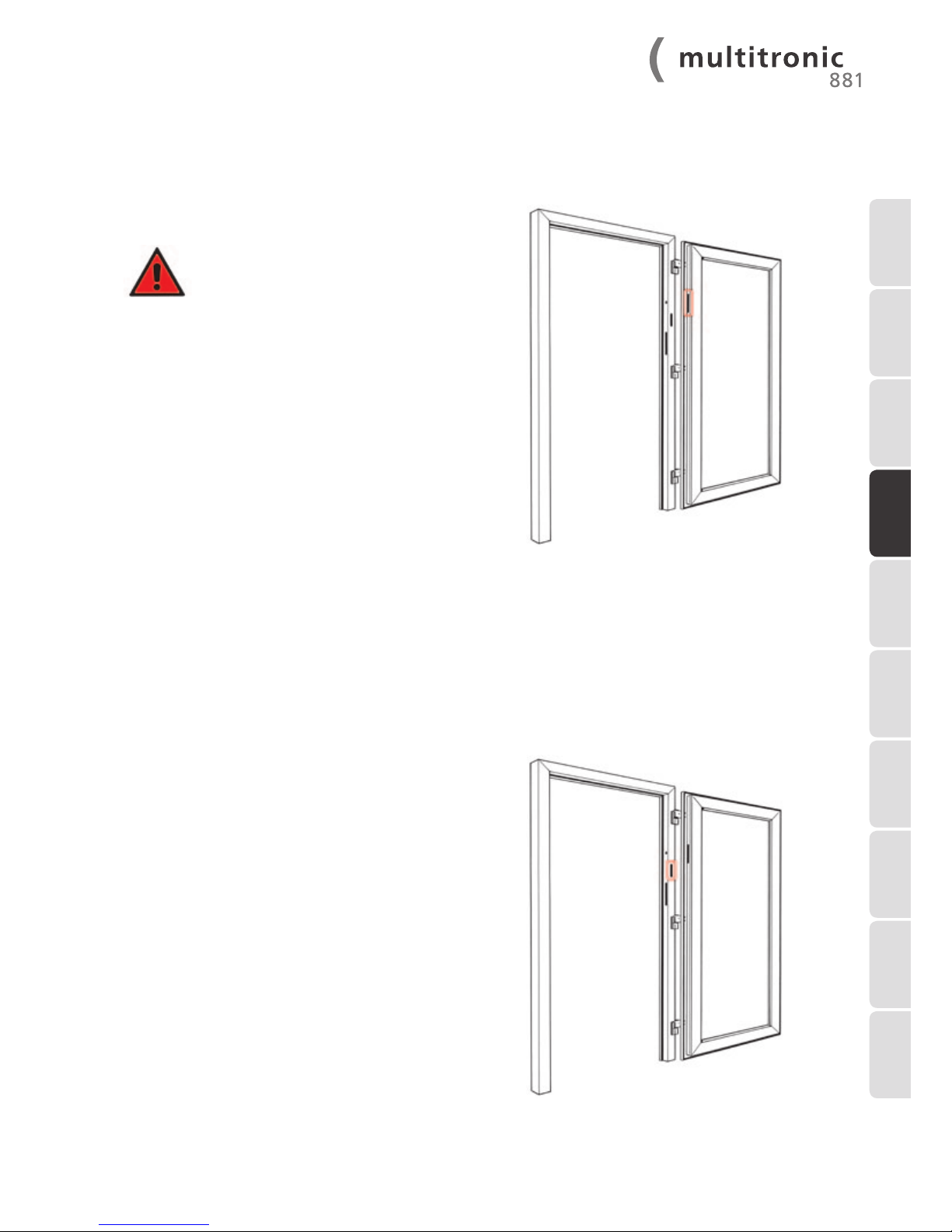
Routing in compliance with the separate routing drawing on
the hinge side of the door leaf
Make sure that the surface-contact device
and the tappet contact device are aligned
accurately horizontally. Refer to chapter
4.1.6.
Routing in compliance with the separate routing drawing on
the hinge side of the door frame face (on the inside of the
building)
4.1.3 Routing for the tappet contacts in the door leaf
4.1.4 Routing for the control unit casing in the door frame
1 INTRODUCTION
2 IMPORTANT
INFORMATION
3 DELIVERY SCOPE8 TROUBLE-
SHOOTING
4 INSTALLATION
INSTRUCTIONS
5 COMMISSIONING
6 EXTERNAL
CONNECTION
OPTIONS
7 MAINTENANCE
AND CARE
9 TECHNICAL
DATA
10 OPTIONAL
ACCESSORIES
Page 10
10
WWW.FUHR.DE
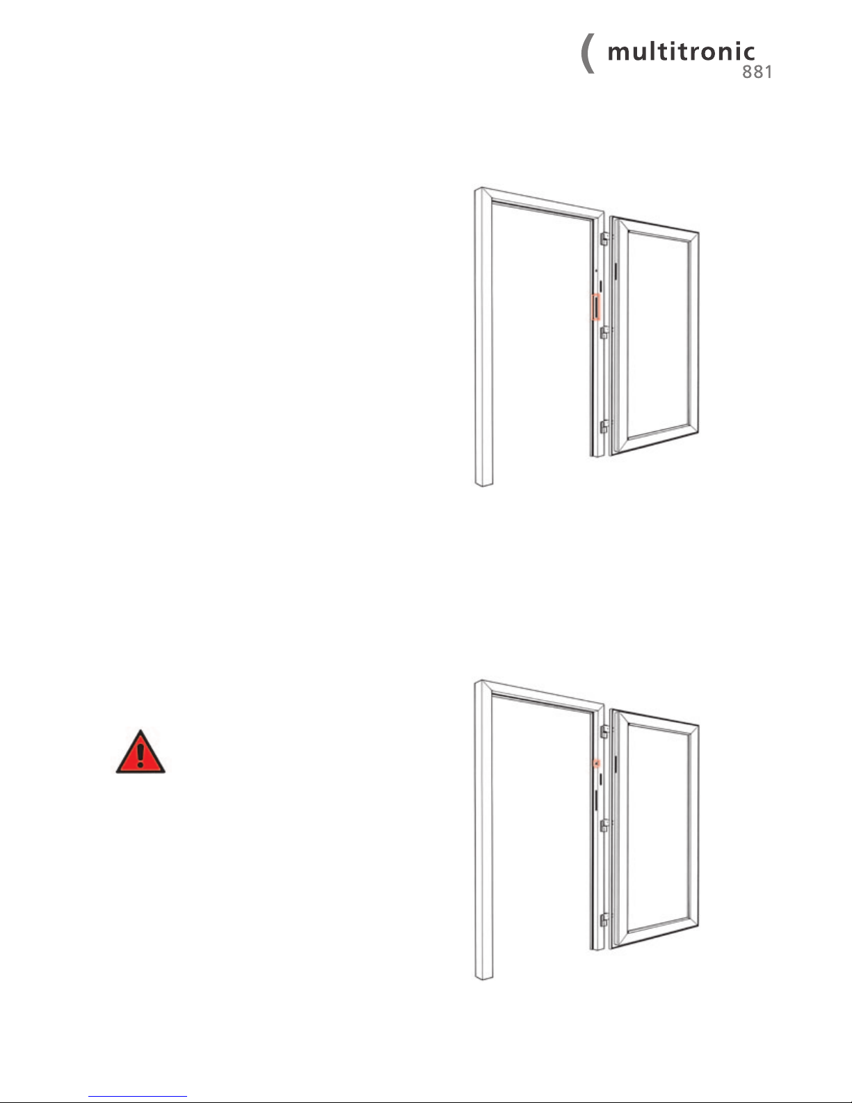
Routing in compliance with the separate routing drawing on
the hinge side of the frame profile
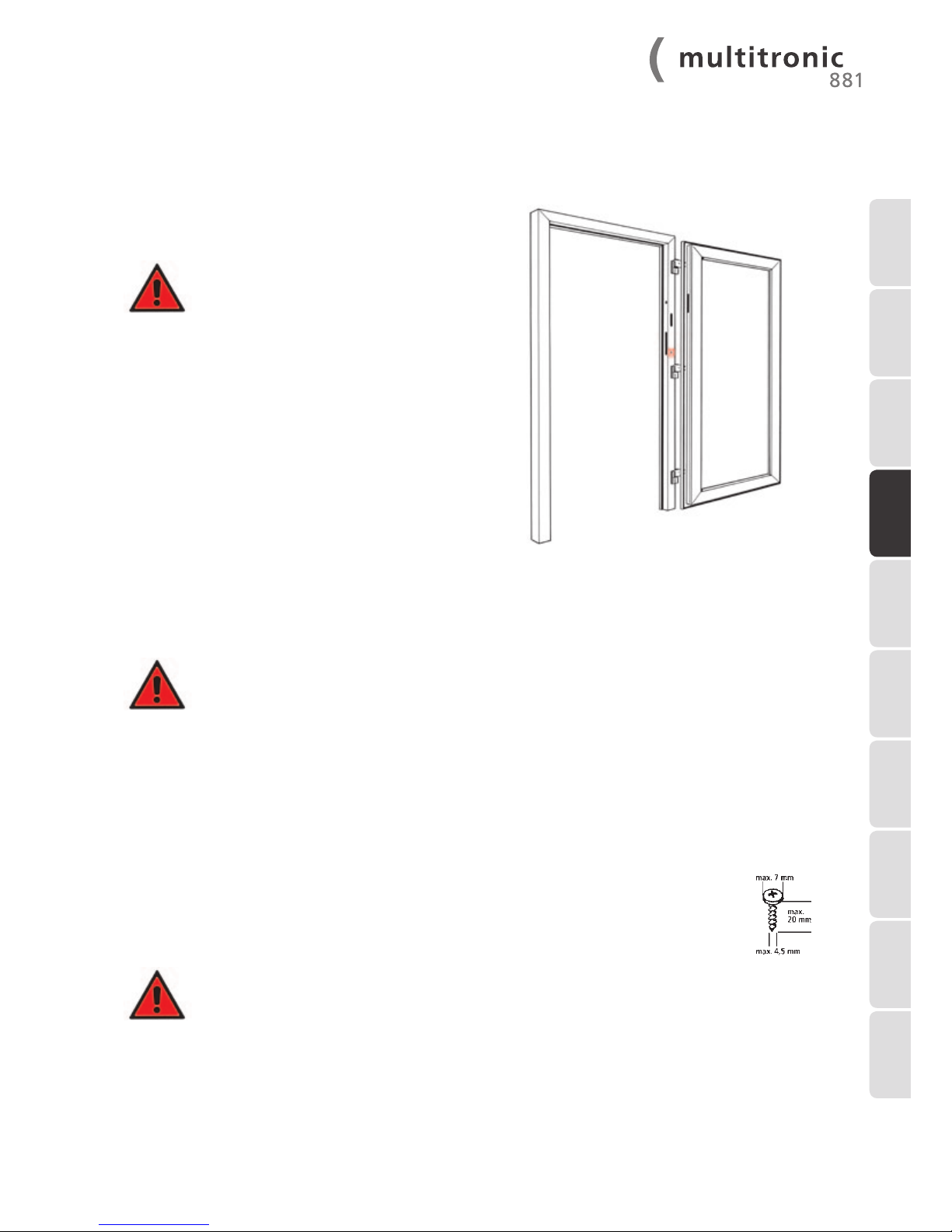
Drilling in compliance with the separate routing drawing in
the frame profile, laterally at the same height as the tappet
contact device
Make sure that the surface-contact device
and the tappet contact device are aligned
accurately horizontally. Refer to chapter
4.1.3.
4.1.5 Routing for the switching power supply unit in the door frame
4.1.6 Drilling for the surface-contact device’s cable
Page 11
11
Drilling in compliance with the separate routing drawing on
the reverse side of the profile within the routing to accommodate the switching power supply unit
This drill hole must deburred carefully
at both ends! Insert the cable protection
sleeve provided in the drill hole to protect
the 230 V cable. The cable must be protected against abrasion and securely fixed
in order to prevent tractive forces.
All routing and drilling work must be deburred carefully. The cables must be securely fixed in this area
in order to prevent abrasion. All routing and drilling swarf must carefully removed from the profiles.
4.1.7 Drilling for the 230 V power supply cable
4.1.8 Safety instructions
Conventional fenestration screws with a maximum screw head diameter of 7 mm and a maximum screw
diameter of 4.5 mm may be used. The PVC components (switching power supply unit, surface-contact
device etc.) are to be fixed with screws with a maximum length of 20 mm. To fix the metal components
(faceplates, keeps etc.) select a screw length according to the requirements.
Depending on the profile material, screw holes may have to be pre-drilled with an appropriate drill.
It is imperative that all screws are hand-tightened, as some components are made
of PVC and may be damaged by the excessive force that a cordless screwdriver can
exert.
It is essential that the surface-contact device and the tappet contact device are
aligned accurately.
4.1.9 Screws for fixing individual components
1 INTRODUCTION
2 IMPORTANT
INFORMATION
3 DELIVERY SCOPE8 TROUBLE-
SHOOTING
4 INSTALLATION
INSTRUCTIONS
5 COMMISSIONING
6 EXTERNAL
CONNECTION
OPTIONS
7 MAINTENANCE
AND CARE
9 TECHNICAL
DATA
10 OPTIONAL
ACCESSORIES
Page 12
12
WWW.FUHR.DE
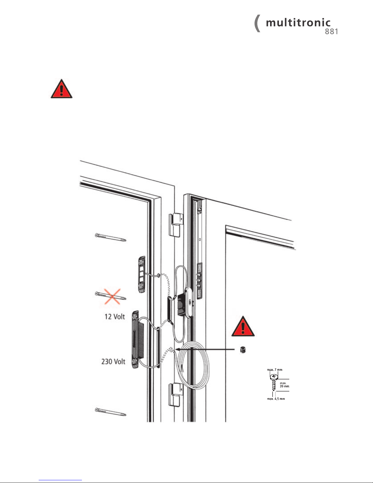
The installation requires exceptional care. This applies particularly to the electronic components, as routing and drilling swarf, abrasion points and defective cables can lead to the device
malfunctioning.
Avoid positioning fixing materials (e.g. frame-fixing screws) in areas where electronic
components are located!
4.2 Installation
Page 13
13
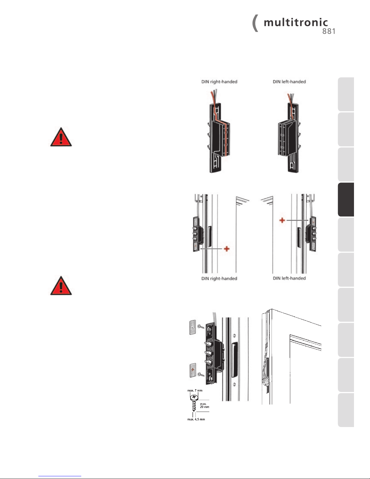
The electricity and data transfer control unit for
FUHR multitronic may be used on left or right
handed doors.
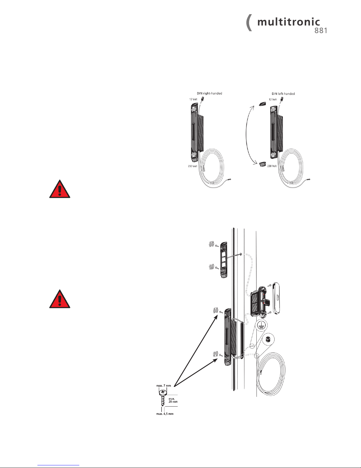
On DIN left-handed doors the tappet contact is installed
as provided.
On DIN right-handed doors the cable is placed in the guide
channel on the rear side of the casing.
Check the polarity (plus/minus) before
installing the tappet contacts, refer to
the components’ identification marking:
DIN right-handed = Plus symbol on
the bottom
DIN left-handed = Plus symbol on
the top
1. Remove the silver covers from the tappet contact device.
2. Insert the tappet contact device into the door leaf’s routed
recess.
3. Lay the cable with the green plug in the channel above the
door.
4. Screw-fix the casing to the door leaf profile.
5. Replace the covers.
6. Insert the green plug in the additional locking point’s top
routing and lead it down to the routed recess for the electrical drive unit.
Note: DIN right-handed = doors with the
hinges located on the right hand side of
the door (viewed from the inside).
4.2.1 Installation of the tappet contacts in the door leaf
1 INTRODUCTION
2 IMPORTANT
INFORMATION
3 DeliveRy sCope
8 TROUBLE-
SHOOTING
4 INSTALLATION
INSTRUCTIONS
5 COMMISSIONING
6 EXTERNAL
CONNECTION
OPTIONS
7 MAINTENANCE
AND CARE
9 TECHNICAL
DATA
10 OPTIONAL
ACCESSORIES
Page 14
14
WWW.FUHR.DE
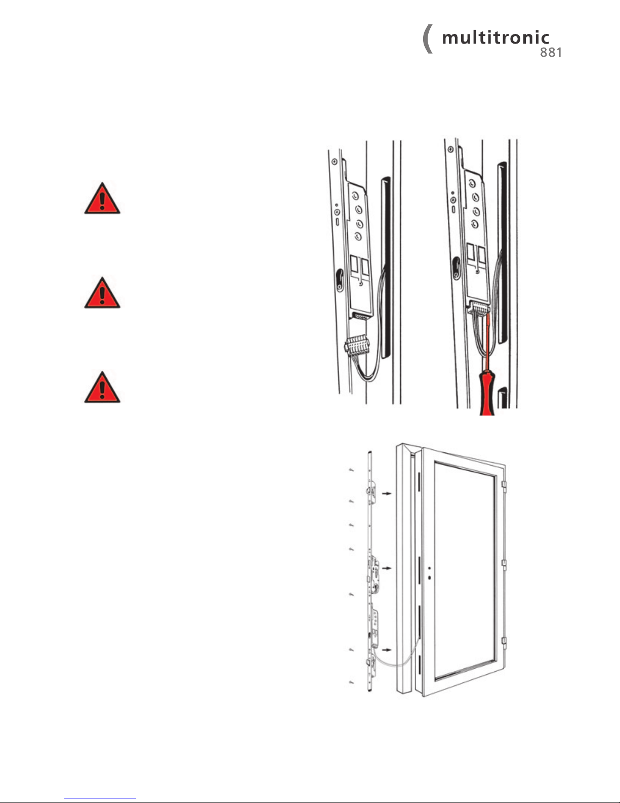
1. Connect the tappet contact device’s green plug to the
corresponding contact plug on the electrical drive unit.
2. Screw-fix the plugs with a small screwdriver.
PLEASE NOTE! It is imperative to carry out
this screw-fixing. The screw joint warrants permanent contact for the electricity
and data transfer, and safeguards against
vibration and shock.
3. Insert the cable and FUHR multipoint locking system
multitronic into the routed recess.
In doing so, ensure that the cables are
neither kinked, trapped nor damaged.
4. Screw-fix the multipoint locking system’s faceplate. Fix
the screws in a straight manner in order to prevent the
connecting-rods being jammed by the screws.
PLEASE NOTE! The connecting-rodshave
to be able to move unhindered. Friction
caused by screws or too narrow profile
guide grooves cause operational malfunction.
4.2.2 Installation of the multipoint locking system in the door leaf
Page 15
15
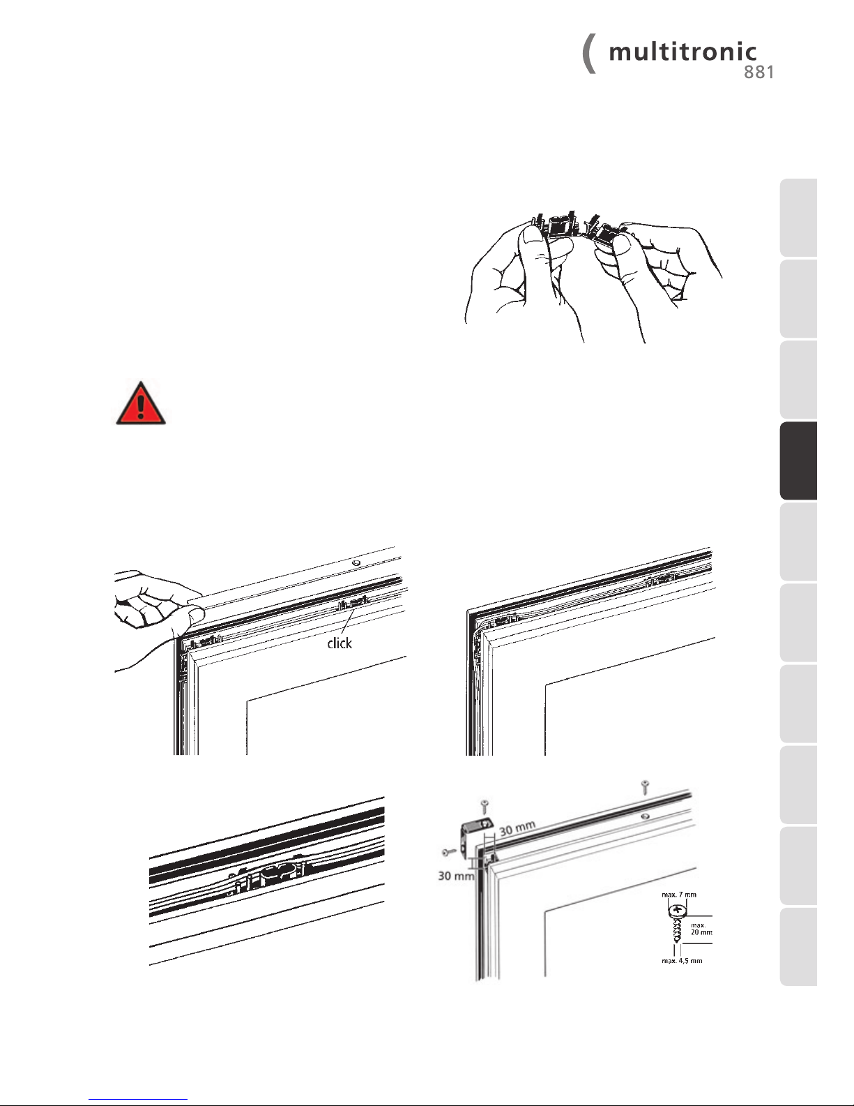
4.2.3 Installation of the cable guides, end caps,
and cover plates in the door leaf
1. Fold the provided PVC cable guides for the profile
corners in half and snap them apart for the centre profile
area.
2. Clip in each of the cable guides into the top door leaf cor-
ners, and depending on the door width and height, also
in the Euro groove channel.
3. Lay the cable through the cable guide and loop the sur-
plus cable between two cable guides.
4. Crop and screw fix the cover plate according to the door
width or height.
Make sure that the screws are screw
fixed through the cable guides’
elongated holes. Non-compliance leads to
damaged cables.
5. Put on the end caps and screw fix through the cable
guides.
1 INTRODUCTION
2 IMPORTANT
INFORMATION
3 DELIVERY SCOPE8 TROUBLE-
SHOOTING
4 INSTALLATION
INSTRUCTIONS
5 COMMISSIONING
6 EXTERNAL
CONNECTION
OPTIONS
7 MAINTENANCE
AND CARE
9 TECHNICAL
DATA
10 OPTIONAL
ACCESSORIES
Page 16
16
WWW.FUHR.DE
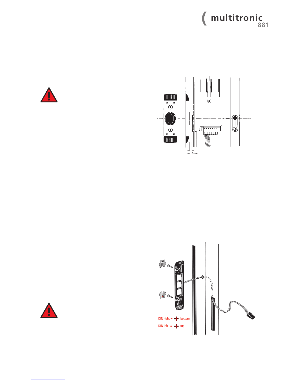
1. Install the magnetic contact in accordance with the sup-
plied routing drawing. The exact drawing dimension must
be adhered to in order to warrant perfect contact with the
electromotive drive’s reed switch.
Make sure that the reed switch and magnet are aligned horizontally at the same
height.
For one-piece keeps:
The installation of the one-piece keep is to be carried
in compliance with routing drawing provided. The
magnetic contact is already integrated.
1. Remove the silver covers.
2. Feed the surface-contact device’s 3-core cable (red,
black, white) through the frame profile’s drill hole and
back outside through the control unit casing’s routed
opening. Pull the cable all the way through the routed
opening so that the surface-contact device is located level
on the profile.
3. Screw fix the surface-contact device to the frame
profile.
4. Replace the covers.
In order to ensure proper contact and
durable operation, the contact surface
has been pre-treated with contact
lubricant. Please do not remove this
lubricant film! Please adhere to the
regular maintenance instructions in
compliance with chapter 7.1.
4.2.4 Installation of the magnetic contact in the door frame
4.2.5 Installation of the surface-contact device in the door frame
Page 17
17
4.2.6 Installation of the control unit casing in the door frame
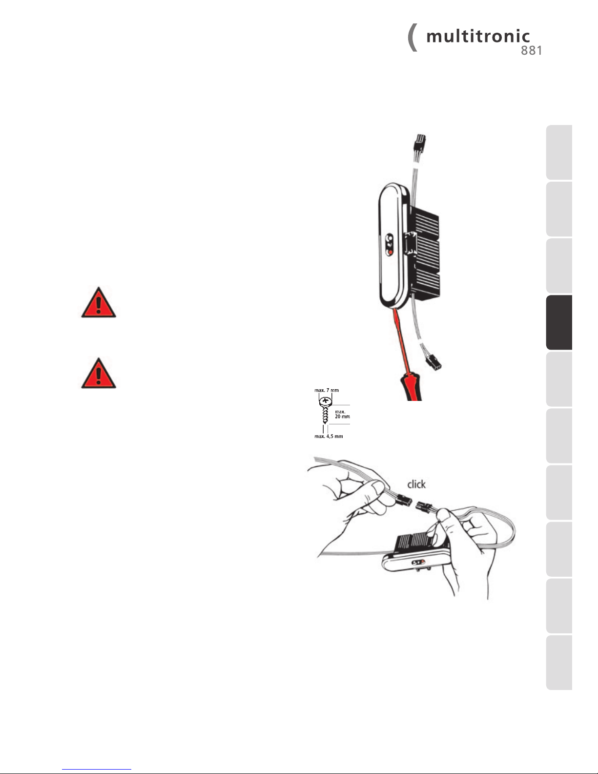
1. Remove the silver cover before installing the control unit
casing. To do so, carefully insert a small screwdriver into
the cover cap’s recess and pry it out.
2. Connect up the surface-contact device’s 3-core cable
plug (red, black, white) with the control unit casing’s
3-core cable plug. The plug clicks in audibly.
3. Insert the 2-core control unit casing cable into the routed
recess, guide the cable downwards, and exit through the
switching power supply unit’s routed recess.
4. Carefully feed the control unit casing’s cable back into the
frame profile so that the control unit casing fits comfortably in the routed recess.
Please ensure that the cables are neither
kinked, trapped nor damaged by sharp
profile edges.
5. Screw fix the control unit casing into the frame profile.
Make sure that the cables are not
damaged when screw fixing.
6. Replace the control unit casing’s cover cap.
1 INTRODUCTION
2 IMPORTANT
INFORMATION
3 DELIVERY SCOPE8 TROUBLE-
SHOOTING
4 INSTALLATION
INSTRUCTIONS
5 COMMISSIONING
6 EXTERNAL
CONNECTION
OPTIONS
7 MAINTENANCE
AND CARE
9 TECHNICAL
DATA
10 OPTIONAL
ACCESSORIES
Page 18
18
WWW.FUHR.DE
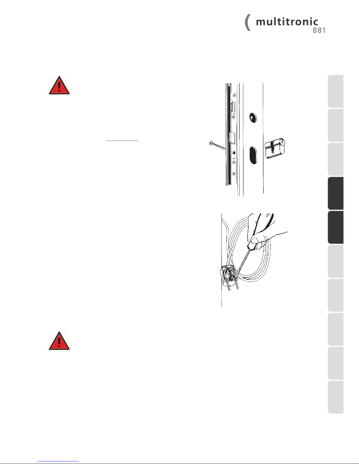
The FUHR multitronic switching power supply unit can be
used for left handed as well as right handed doors.
On DIN right-handed doors the switching power supply
unit is installed as provided.
On DIN left-handed doors the top profile-related end cap is
swopped with the bottom one.
1. Remove the silver covers.
2. The green/yellow earth/ground cable is to be connec-
ted electrically conducting with the door’s metal frame.
3. Connect up the control unit casing’s 2-core cable (red/
black) with the switching power supply unit’s cable counterpart. The plug clicks in audibly.
4. Feed the cable carefully back into the frame profile
ensuring that the switching power
supply unit fits comfortably in the
routed recess.
Depending on the profile type, loop the cable at the
bottom of the profile.
5. Guide the 230 V cable out through the deburred drill
hole at the bottom of the profile (through the inserted
cable protection sleeve). Leave a spare cable loop in the
profile in order to be able to remove the switching power
supply unit at a later time. Fix the rolled up cable to resist
tractive forces and fasten it to the outside of the door
frame using a cable tie.
6. Screw fix the switching power supply unit to the frame
profile.
Make sure that the cables are not
damaged when screw fixing. Earth/ground
the frame before commissioning.
7. Replace the covers.
4.2.7 Installation of the switching power supply unit (transformer)
in the door frame
Page 19
19
1. Install the door in the wall opening in the usual manner, guiding the 230 V cable to the
internal side of the wall. Make sure that fixing materials (e.g. wall anchors) are not located where
the electronic components are.
2. An electrician must connect up the 230 V cable to the power supply. The door frame’s earthing/
grounding is to be professionally checked. Conduit must be used for 230 V concealed cabling.
3. In order to be able to warrant the power supply of all electronic components, also in the case
of a network operator’s power failure, escape doors in accordance with DIN EN 179 and
DIN EN 1125 should be equipped with an emergency power supply!
1. After all of the FUHR multitronic components have been installed, check
that the door leaves and frames are
aligned parallel.
2. Install a profile cylinder with free-running mechanism
and forced decoupling in the centre lock in accordance
with the certificates of EN 179/EN 1125 resp. with the
marking ‘FZG’. A current list of the non-restricted cylinders which are approved with our multipoint locks can be
found on our website at www.fuhr.de.
3. Subsequently connect the 230 V cable to the mains voltage by means of a two-pin earthed/grounded plug for
testing purposes (only by qualified personnel).
4. The green LED will light up as soon as operating
voltage is present. 3 seconds after the door is closed (the
reed switch is triggered by the magnetic contact); the
lock device will lock automatically.
5. In order to test all functions, the door should be opened
and locked several times via the drive unit, the profile
cylinder, and via the lever-handle. In the event of any
problems arising, please refer to chapter 8.
6. If the FUHR multitronic lock is fully operational, the twopin earthed/grounded plug can be removed and the door
can be despatched.
5 Commissioning
5.1 Fabricator’s function check
5.2 Commissioning on site
1 INTRODUCTION
2 IMPORTANT
INFORMATION
3 DELIVERY SCOPE8 TROUBLE-
SHOOTING
4 INSTALLATION
INSTRUCTIONS
5 COMMISSIONING
6 EXTERNAL
CONNECTION
OPTIONS
7 MAINTENANCE
AND CARE
9 TECHNICAL
DATA
10 OPTIONAL
ACCESSORIES
Page 20
20
WWW.FUHR.DE
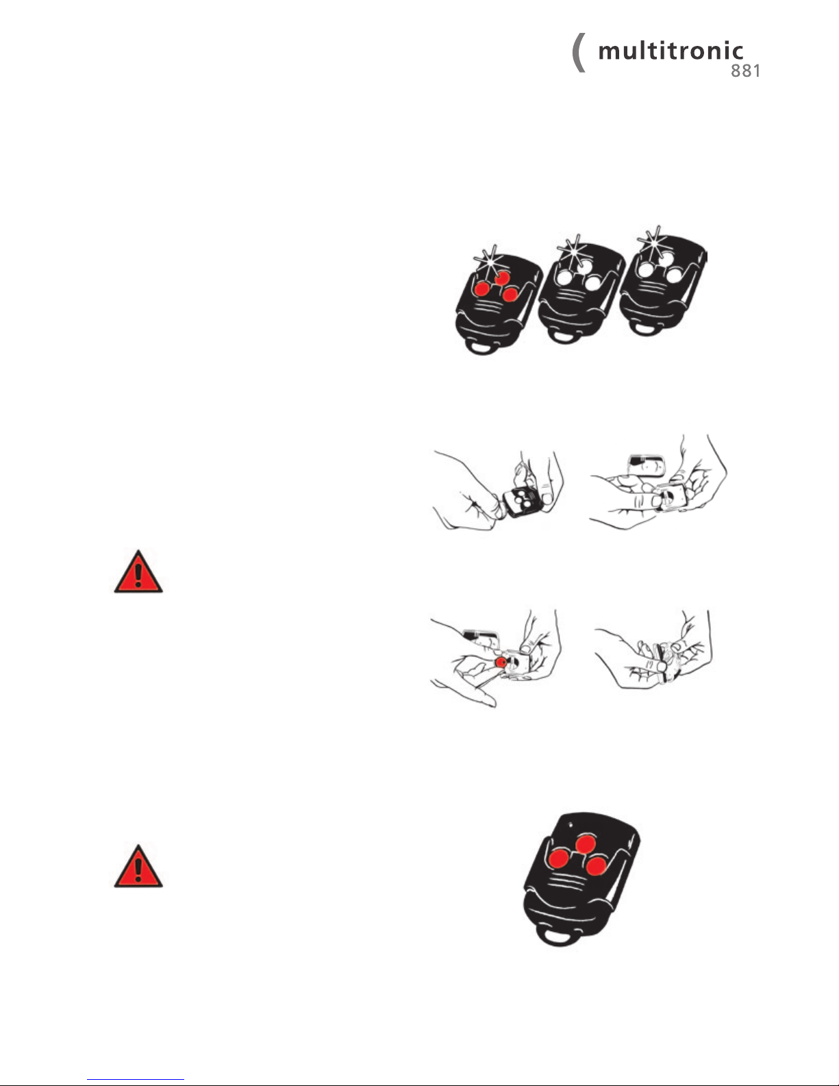
The FUHR multitronic is supplied with 3 radio keys (radiocontrolled remote controls). All radio keys are copy protected
by means of a ‘rolling code system’.
The radio key with the red buttons is defined as the master
key and is needed to tune in the other radio keys. Up to 25
radio keys can be tuned in.
The radio keys are equipped with a three channel radiocontrolled remote control. The individual buttons
(channels) are allocated as follows:
Centre button – Main door – Tuned in on site
Left button – Free for e.g. garage door
Right button – Free for e.g. garden gate
The radio key is equipped with a battery-operated indicator
light. The radio keys are particularly energy saving. One battery suffices for approx. 50,000 operations.
Battery change:
1. Open the radio key casing with a coin.
2. Slide the battery out.
3. Insert the new battery (type: CR 2032). Note that the
Plus symbol is pointing upwards.
4. Press the radio key casing together again.
Important!
In order to ensure that the door can be
opened in the event of an emergency (e.g.
power failure), the profile cylinder key
should always be carried in addition to the
radio key.
The radio key with the red buttons serves as the master key.
Only this key has the ability to tune in or delete other radio
keys. The master radio key’s middle button has already been
tuned in at the factory to the control unit within the same set.
The master key cannot be deleted or
switched at a later stage.
The master key should therefore be
kept safely, as additional keys cannot
be tuned in or deleted should it be lost.
5.4 Master radio key
5.3 The radio keys (radio-controlled remote control)
Page 21
21
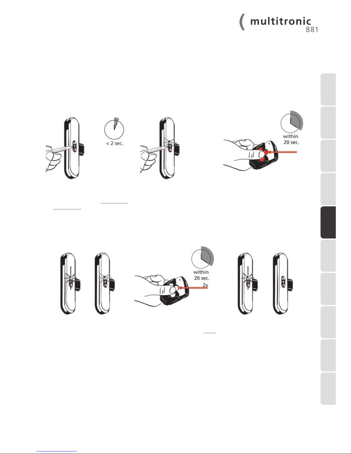
1. During the initial commissioning, all radio keys should, for security reasons be deleted as described in chapter 5.5.3.
Subsequently proceed from step 2.
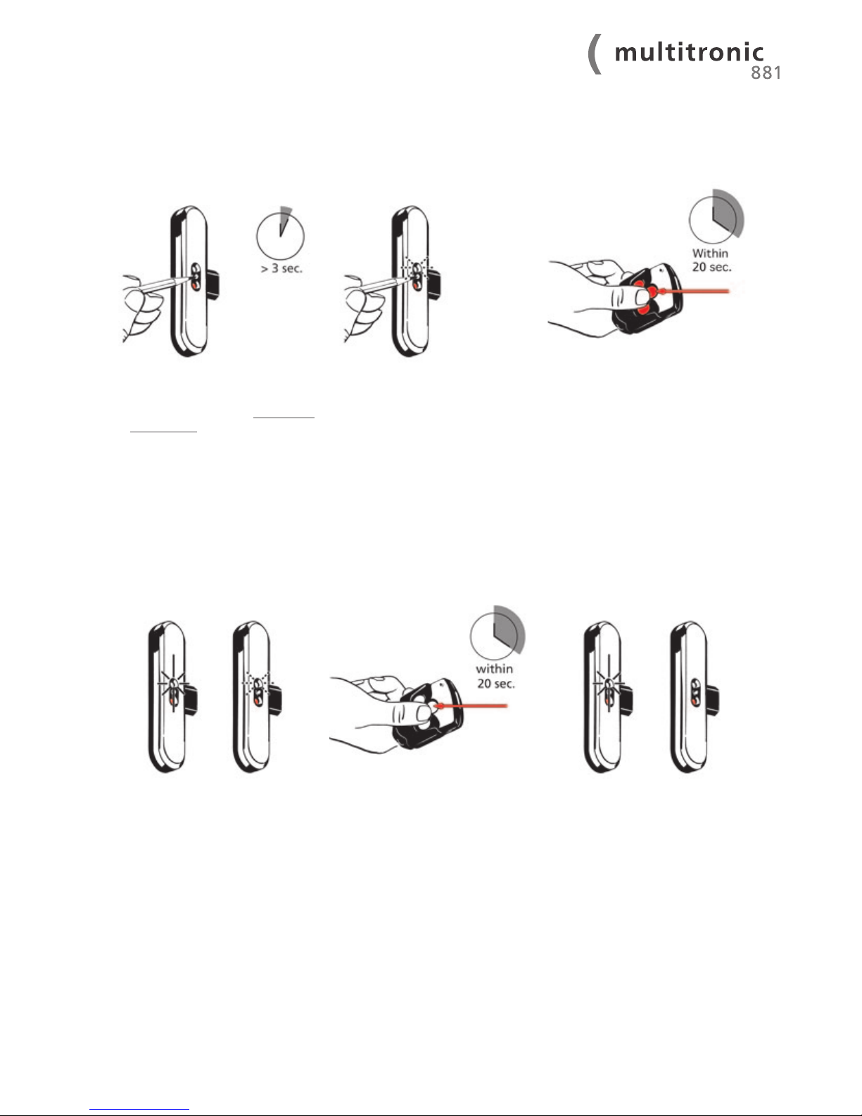
3. The green LED flashes slowly.
4. Now press the master key’s middle
transmitter button within 20 sec.
5. If the control unit accepts the
master key, the green LED
lights up for 2 seconds and then
continues to flash slowly.
6. Press the middle button twice
consecutively of the new radio key
to be tuned in within 20 seconds.
The tuning in procedure is aborted if the 20 second time limit is
exceeded.
7. If the new radio key has been
accepted by the control unit, the
green LED lights up for 1 second
and then goes out.
8. Repeat from step 2, should you wish to tune in another radio key.
5.5 Tuning in and deleting the radio keys
5.5.1 Tuning in individual radio keys (max. 25)
2. Close the door and press the
programming button briefly (less
than 2 sec.) between the control
unit casing’s red and green LED with
a thin object (e.g. ballpoint pen or
pencil).
1 INTRODUCTION
2 IMPORTANT
INFORMATION
3 DELIVERY SCOPE8 TROUBLE-
SHOOTING
4 INSTALLATION
INSTRUCTIONS
5 COMMISSIONING
6 EXTERNAL
CONNECTION
OPTIONS
7 MAINTENANCE
AND CARE
9 TECHNICAL
DATA
10 OPTIONAL
ACCESSORIES
Page 22
22
WWW.FUHR.DE
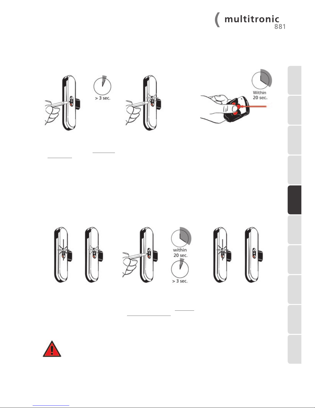
1. Close the door and press the
programming button for longer
than 3 sec. between the control
unit casing’s red and green LED with
a thin object (e.g. ballpoint pen or
pencil).
2. Release the programming button
as soon as the green LED flashes
quickly.
3. Now press the master key’s middle
transmitter button within 20 sec.
4. If the control unit accepts the
master key, the green LED
lights up for 2 seconds and then
continues to flash slowly.
5. Press the middle button of the
radio key to be deleted within
20 seconds. The delete process is
aborted if the 20 second time limit
is exceeded.
6. If the transmission code has been
successfully deleted, the green LED
lights up for 1 second and then goes
out.
7. Repeat from step 1, should you wish to delete another radio key.
5.5.2 Deleting individual radio keys (except the master key)
Page 23
23
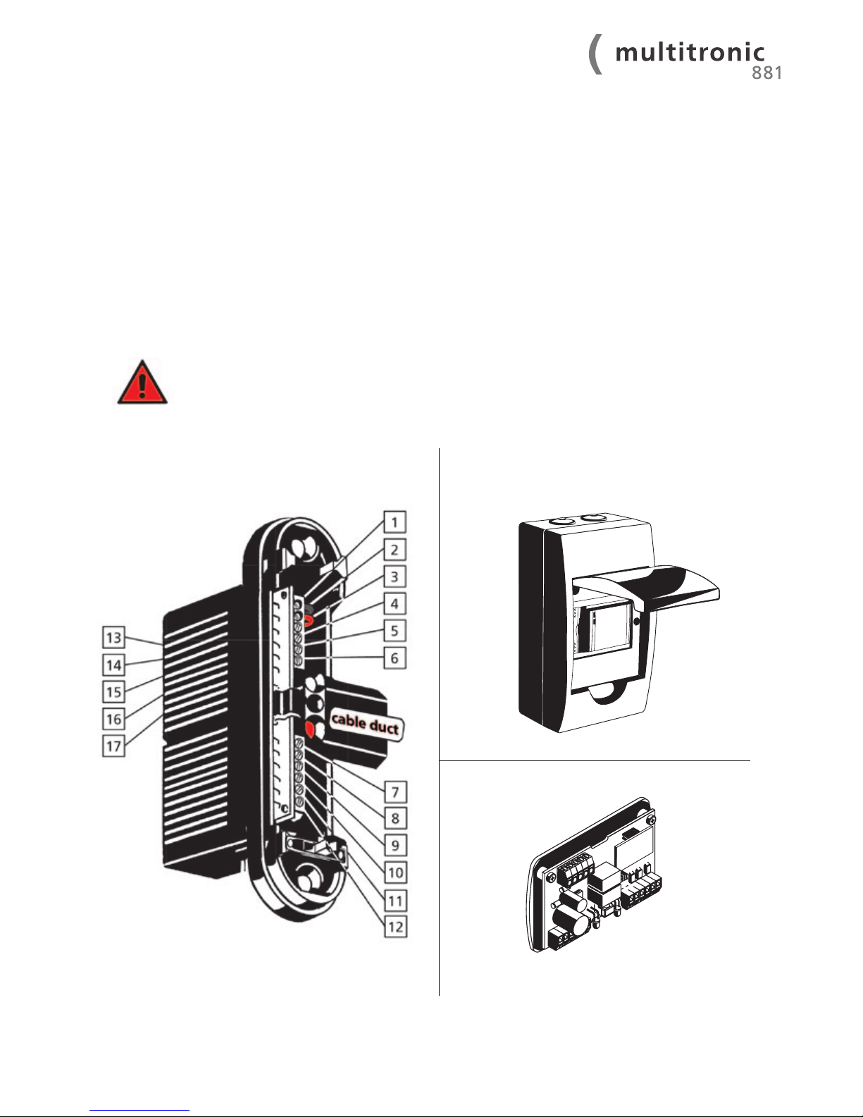
1. Close the door and press the
programming button for longer
than 3 sec. between the control
unit casing’s red and green LED with
a thin object (e.g. ballpoint pen or
pencil).
2. Release the programming button
as soon as the green LED flashes
quickly.
3. Now press the master key’s middle
transmitter button within 20 sec.
4. If the control unit accepts the
master key, the green LED
lights up for 2 seconds and then
continues to flash quickly.
5. Now press the programming
button on the control unit again
within 20 seconds for longer than 3 seconds. The delete
process is aborted if the 20 second
time limit is exceeded.
6. If all of the transmission codes
(except the master transmission
code) have been successfully
deleted, the green LED lights up for
1 second and then goes out.
Note: If the master key is not recognised during the tuning-in and delete processes, the respective
function is aborted.
5.5.3 Deleting all radio keys (except the master key)
1 INTRODUCTION
2 IMPORTANT
INFORMATION
3 DELIVERY SCOPE8 TROUBLE-
SHOOTING
4 INSTALLATION
INSTRUCTIONS
5 COMMISSIONING
6 EXTERNAL
CONNECTION
OPTIONS
7 MAINTENANCE
AND CARE
9 TECHNICAL
DATA
10 OPTIONAL
ACCESSORIES
Page 24
24
WWW.FUHR.DE
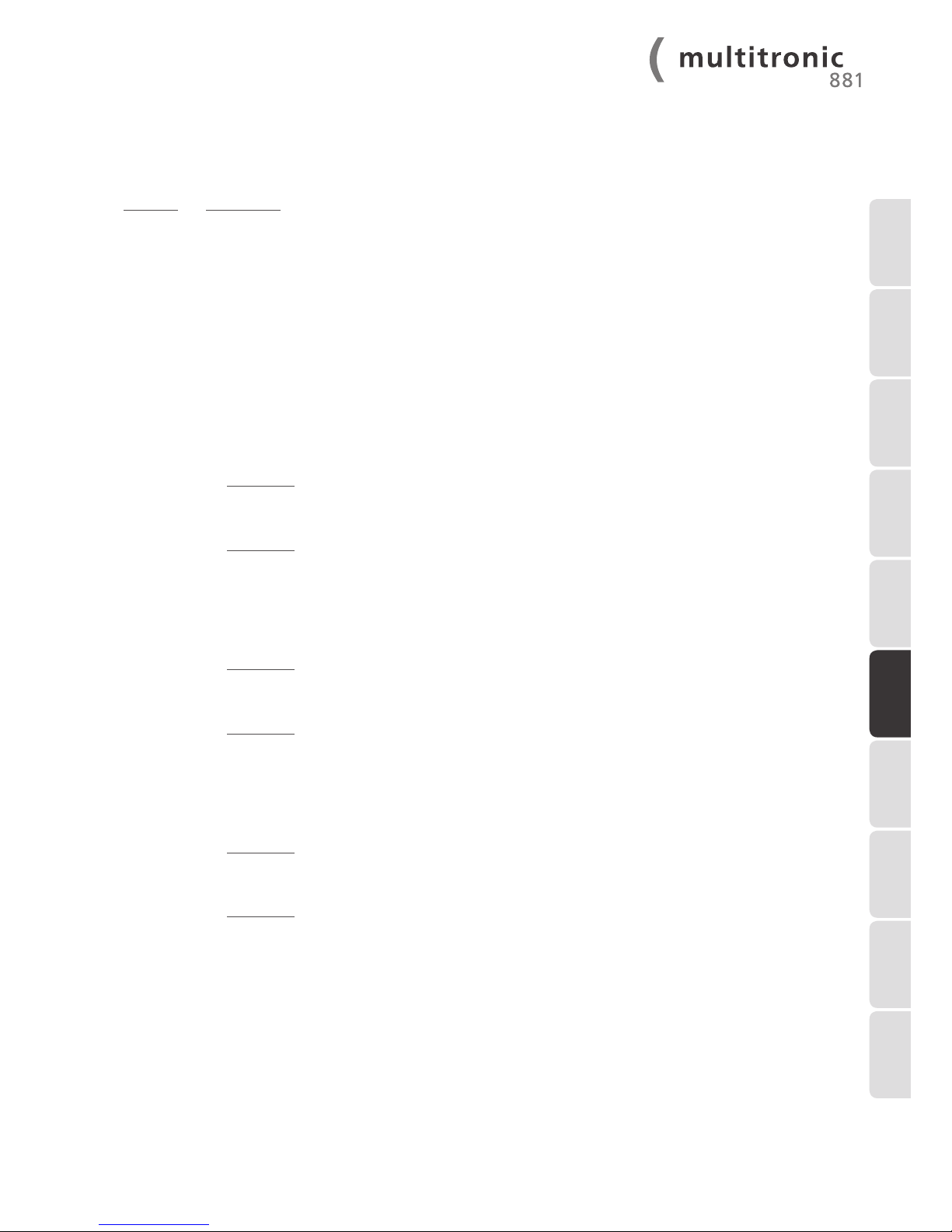
The FUHR multitronic control unit is equipped with a multitude of input and output sockets to connect additional components (such as e.g. transponder, eye scan, finger print, code locks, electrical swing door opener, alarm systems, facility
management systems etc.). The input and output sockets are located:
•On the frame: under the surface-mounted control unit casing’s cover plate (refer to 6.1)
•On the leaf: multi-functional jack of the FUHR multitronic drive unit (refer to 6.2).
Outlined below are some examples of the potential allocation of the control unit’s connection terminals.
Note: Equip the control unit casing mounted on the door frame with a surface-mounted cable duct
if concealed cable laying of individual external connection cables is required. Connection cables
pertaining to surface-mounted access control devices may be fed through this surface-mounted
cable duct to the FUHR multitronic control unit casing.
6 External connection options
6.1 Control unit casing circuit-board
Rail-mounted control
Control box with integrated
mains adapter
Page 25
25
Terminal Assignment
1 + 2: Already occupied by the 12 V DC switching power supply unit’s power supply.
3 + 4: Output – e.g. for electrical swing door openers.
Immediately after the FUHR multitronic lock has been opened via radio control, transponder etc., a relay
triggers the make contact for 2 seconds. This impulse is processed by the swing door opener’s control unit
and triggers the swinging movement of the door leaf.
The “DRT” jumper can be removed if required (refer to the wiring diagram on page 36), enabling the swing
door opener’s output to be triggered just as long as a continuous signal is applied to the latch retaining
function (terminal 9 & 10).
5 + 6: Output –e.g. for alarm systems.
Opening the door leaf and unlocking the lock triggers the related opener contact within 3 seconds. This
remains triggered until the door leaf is closed over and the lock has been locked. An alarm system control
unit processes the signal status and reports back ‘OPEN’ or ‘CLOSED’.
7 + 8: Input for 6-12 V AC (alternating current) or 6-24 V DC (direct current)
– optionally, this input can be used with two modes of operation:
Function 1:
Standard opening with subsequent complete locking after 3 seconds
If a 1 sec. impulse is applied to this input (e.g. activated via a building management system) the
FUHR multitronic lock will open.
Function 2:
Opening with day latch function
If a continuous signal is applied to this input (e.g. activated via a time switch) the FUHR multitronic lock
will open. Upon opening the door leaf or after 5 seconds, only the lock’s latch protrudes. All bolts remain
withdrawn as long as the continuous signal is applied.
9 + 10: Input for potential-free signals
– optionally, this input can be used with two modes of operation:
Function 1:
Standard opening with subsequent complete locking after 3 seconds
If a potential-free impulse ≤ 1 second is applied to this input (e.g. controlled via an access control sys-
tem) the FUHR multitronic lock will open
Function 2:
Opening with day latch retaining function
If a potential-free continuous signal is applied to this input (e.g. controlled via a time switch) the
FUHR multitronic lock will open. The latch and all bolts remain withdrawn as long as the continuous signal
is applied.
11 + 12: Input for potential-free signals
– optionally, this input can be used with two modes of operation:
Function 1:
Standard opening with subsequent complete locking after 3 seconds
If a potential-free impulse ≤ 1 second is applied to this input (e.g. controlled via an access control sys-
tem) the FUHR multitronic lock will open.
Function 2:
Opening with day latch function
If a potential-free continuous signal is applied to this input (e.g. controlled via a time switch) the FUHR
multitronic lock will open. Upon opening the door leaf or after 5 seconds, only the lock’s latch protrudes.
All bolts remain withdrawn as long as the continuous signal is applied.
The “TGF” jumper can be removed if required (refer to the wiring diagram on page 36), enabling the lock’s
latch to no longer retract motor-driven upon the first day-latch activation.
13 - 15: Already occupied by the electricity and data transmission.
16 + 17: Input for potential-free signals.
All motorised opening functions (radio receiver and control terminals 7-12) are deactivated as long as this
input remain triggered. The opening impulses via the motor's circuit board (terminal 4/7) are also deactivated.
1 INTRODUCTION
2 IMPORTANT
INFORMATION
3 DELIVERY SCOPE8 TROUBLE-
SHOOTING
4 INSTALLATION
INSTRUCTIONS
5 COMMISSIONING 6 EXTERNAL
CONNECTION
OPTIONS
7 MAINTENANCE
AND CARE
9 TECHNICAL
DATA
10 OPTIONAL
ACCESSORIES
Page 26
26
WWW.FUHR.DE
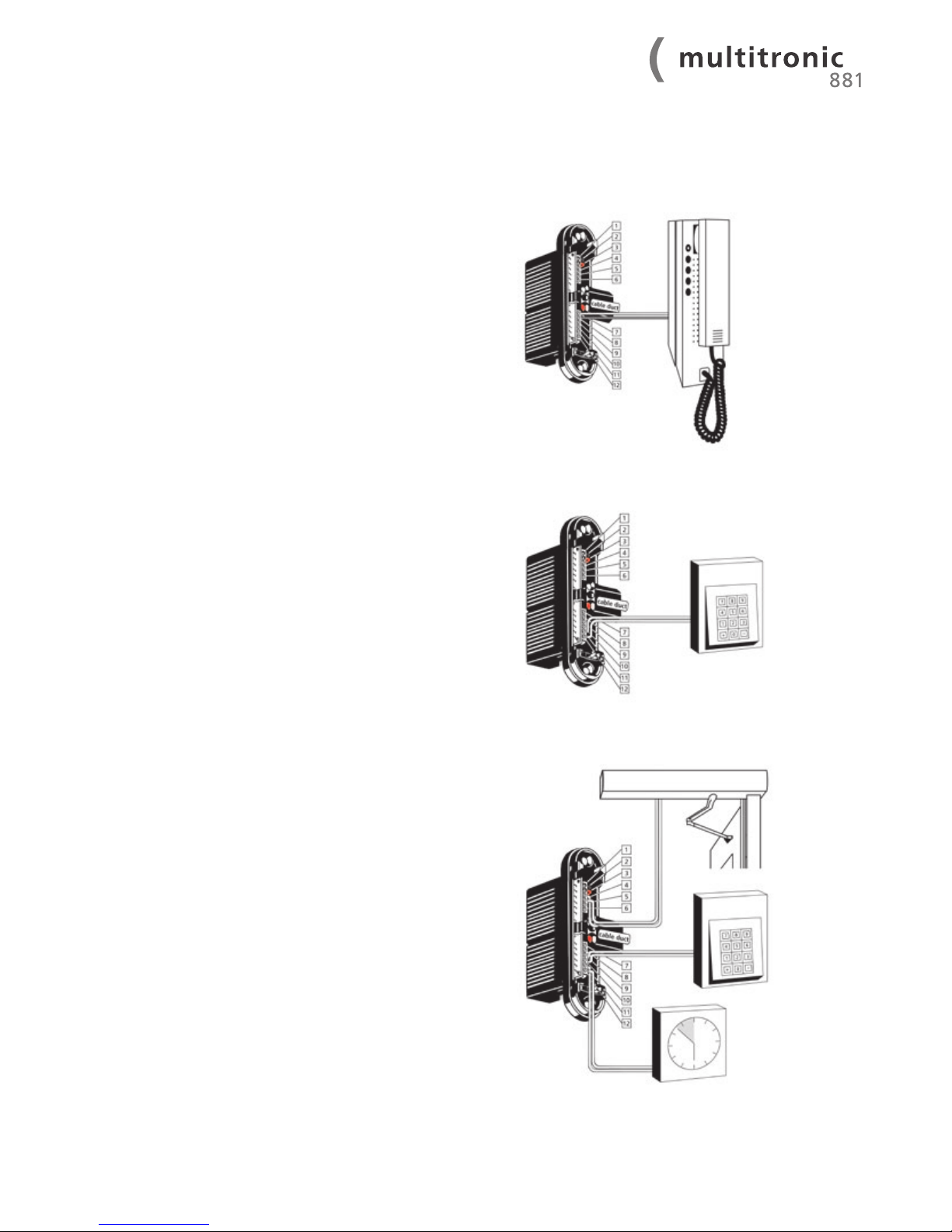
6.1.1 Application examples for circuit board assignment
Application example in residential buildings:
For example the door shall be opened via radio key from
the outside. The opening is triggered from the inside by
means of an existing two-way intercom system with a
12 V AC control cable. This was, as the case may be, used
previously for an electrical door opener.
Terminal assignment:
Connect the two-way intercom system’s cables to terminal
7 + 8.
Application examples in residential/public
buildings:
The opening shall be triggered from the outside by means of
an access control system (e.g. numeric code lock or finger
print).
Terminal assignment:
Connect the access control system with potential-free
impulse (≤ 1 sec.) to terminals 11 + 12.
Application example in construction projects:
The door shall be locked during the day for example by
means of the latch only. At night the lock shall be locked both
completely and fully automatically. Opening from the outside is triggered by means of an access control system (e.g.
numeric code lock or finger print). In addition, an electrical
swing door opener shall open the door leaf.
Terminal assignment:
Connect the time switch with potential-free continuous
signal to terminals 11 + 12 for function 2.
Connect the access control system with potential-free
impulse (≤ 1 sec.) to terminals 9 + 10 for function 1.
Connect the swing door opener to terminals 3 + 4.
Page 27
27
The below-mentioned applications are merely intended as application examples of common connections. Furthermore there
is a multitude of other possible applications.
It is important that the respective switching signal (e.g. the 12 V DC impulse or the potential-free
contact etc.) is connected to the appropriate terminal.
We recommend the use of shielded cables in order to avoid interference from external sources and
ensure proper functioning.
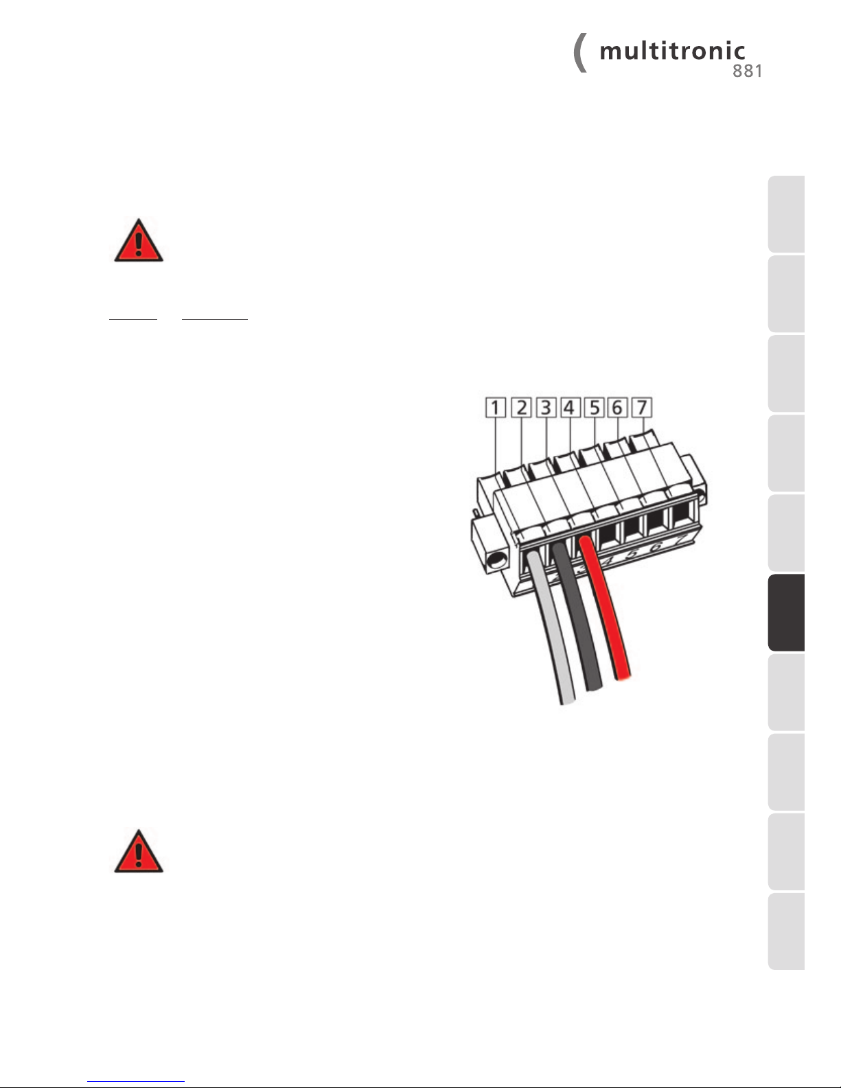
6.2 The drive unit’s multi-functional jack
Terminal Assignment
1 + 2 + 3 Already occupied by the 12 V DC drive unit’s
power and data supply cable.
4 + 5 Input (impulse < 1 sec.) – e.g. for exter-
nal access control systems (transponders,
code locks, finger print, eye scan… etc.),
that are mounted directly on the door leaf.
By means of either the access control
system’s control unit or by pressing a
switch, a brief potential-free contact triggers opening the FUHR multitronic lock.
5 + 6 Output – ideally used for the power supply of
illuminated fixed pad handles or illuminated glazed panels.
Terminal 5 = GND (earth/ground) and
terminal 6 = 12 V DC (max. 350 mA).
5 + 7 Input (impulse 1 sec.) – e.g. for code locks
or transponder systems, that are mounted
directly on the door leaf.
Terminal 5 = GND (earth/ground) and
terminal 7 = 12 V DC
Input signal to open the lock = 12 V DC.
1 INTRODUCTION
2 IMPORTANT
INFORMATION
3 DELIVERY SCOPE
8 TROUBLE-
SHOOTING
4 INSTALLATION
INSTRUCTIONS
5 COMMISSIONING
6 EXTERNAL
CONNECTION
OPTIONS
7 MAINTENANCE
AND CARE
9 TECHNICAL
DATA
10 OPTIONAL
ACCESSORIES
Page 28
28
WWW.FUHR.DE
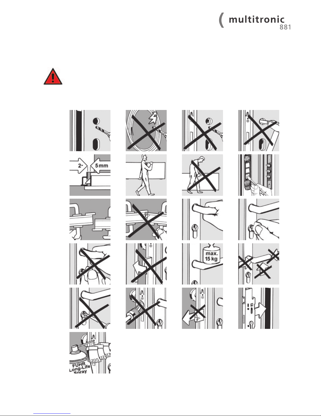
The points raised below are intended as an addition to the FUHR product information M3/3. The
importance of their compliance must be pointed out to builders and users alike. In the event of non-
compliance with these necessary instructions, faultless operation of the locks cannot be guaranteed.
The FUHR multitronic lock may only be used in conjunction with the components provided. Failure to
do so invalidates warranty issues.
7 Maintenance and care
Page 29
29
All safety-relevant hardware must be checked at least annually for wear and tear and if mechanically secured. Depending on
the requirements, fixing screws must be tightened or the damaged or worn parts exchanged for original parts by a specialised
company.
Additionally all movable parts and locking points must be lubricated and their function must be checked. Only cleaning and
maintenance agents, which do not damage the corrosion protection of the hardware components, are to be used. Hardware
adjustments as well as replacing hardware components must be carried out by a specialist company.
We recommend you consider a service and maintenance contract with a specialist company.
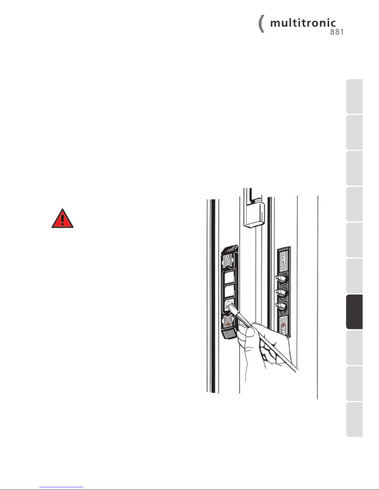
In order to ensure perfect contact bet-
ween the contact surfaces and the
tappet contacts, we recommend
that the surfaces are treated with the
provided contact lubricant twice a year.
(The contact lubricant can be reordered under
the item no. NZ80077.)
7.1 Contact device
1 INTRODUCTION
2 IMPORTANT
INFORMATION
3 DELIVERY SCOPE8 TROUBLE-
SHOOTING
4 INSTALLATION
INSTRUCTIONS
5 COMMISSIONING 6 EXTERNAL
CONNECTION
OPTIONS
7 MAINTENANCE
AND CARE
9 TECHNICAL
DATA
10 OPTIONAL
ACCESSORIES
Page 30
30
WWW.FUHR.DE
In the event that your FUHR multitronic lock should fail to function properly, please refer to the table below to find and rectify
the fault.
IMPORTANT! The entire FUHR multitronic lock has been subject to extensive inspections by the
manufacturer. If faults are found once installed, the installation should be checked to begin with. The
FUHR multitronic lock must never be opened forcefully using the lever-handle! All components have
been designed for a smooth running operation. The FUHR multitronic lock has not been designed to
straighten out warped or distorted doors! Careful and proper installation and maintenance of the
door is a prerequisite for durable, trouble free operation.
8 Troubleshooting
Type of fault Signal Possible cause of fault Fault repair
The lock does not lock
completely.
Green and red LEDs
flash alternately.
Deadbolt doesn’t run smoothly.
Open the lock using the radio key
or the key. (Not with force via the
lever-handle!)
The door is warped. Check the door installation and
possibly adjust.
The keeps have been adjusted too
tightly.
Readjust/loosen keeps.
The locking bolts are obstructed. Check as to whether all keeps are
freely accessible.
A profile cylinder without freerunning mechanism has been
installed.
Install a non-restricted profile
cylinder (refer to 5.1).
The lock does not lock
or unlock.
Green and red LEDs
light up.
Data connection between the
electronic drive unit and the control unit is interrupted.
Check if the spring-loaded tappet
contacts are correctly poled (note
+/-; refer to 4.2.1 and 4.2.5).
Are the spring-loaded tappet
contact pins meeting the flat surface contact when the door is
closed over?
One or more cables are
damaged.
Check all cables and plug-andsocket connections.
Tappet contacts and contact
surfaces have no contact.
Lubricate the contact surfaces
(refer to 7.1).
The lock does not lock. Green LED lights up. Reed switch is not triggering.
Magnet is out of range.
Readjust the magnet and/or
door. Check the clearance.
No LED lights up Power and data connection bet-
ween the electronic drive unit
and the control unit has shortcircuited.
Check if the spring-loaded tappet
contacts are correctly poled (note
+/-; refer to 4.2.1 and 4.2.5).
Connect the cable properly to the
green multi-functional jack (refer
to 6.2).
Page 31
31
1 INTRODUCTION
2 IMPORTANT
INFORMATION
3 DELIVERY SCOPE8 TROUBLE-
SHOOTING
4 INSTALLATION
INSTRUCTIONS
5 COMMISSIONING 6 EXTERNAL
CONNECTION
OPTIONS
7 MAINTENANCE
AND CARE
9 TECHNICAL
DATA
10 OPTIONAL
ACCESSORIES
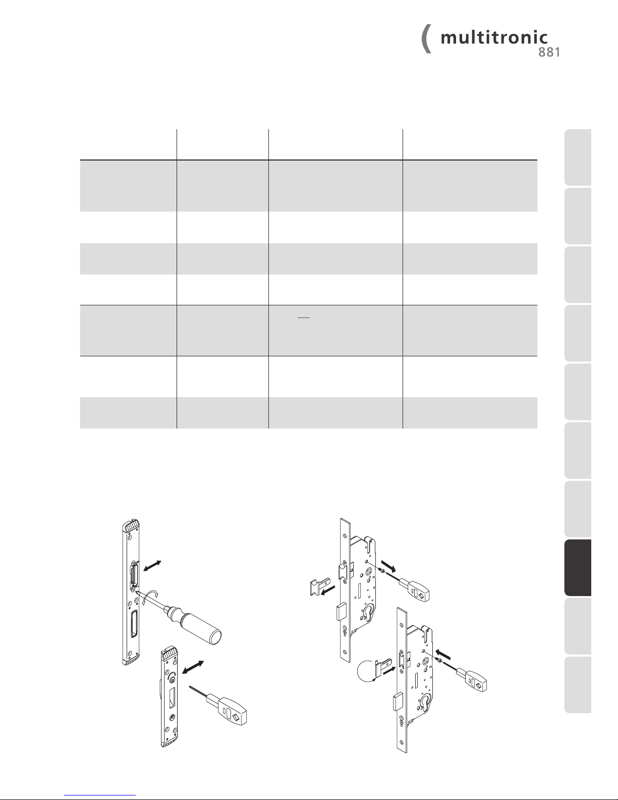
± 2 mm
adjustment of strike
plates/one-piece strike
plates
± 1.6 mm
SW 4
SW 2
SW 2
latch changing
SW 2
SW 2
8.1 Adjustment of strike plates/one-piece strike plates and latch changing
Type of fault Signal Possible cause of fault Fault repair
The door cannot be
opened by the radio
key or by an external
opening impulse.
Red LED lights up. The radio key is not tuned in. Tune in the radio key.
The distance to the receiver is too
large.
Hold the radio key closer to the
door.
The batteries in the radio key are
too weak.
Hold the radio key closer to the
door and replace the battery.
The control software is blocked. Reset the control (switch the
power supply off and on).
Door was opened. Green and red LEDs
light up.
This is not a fault. A signal is being
transmitted to indicate that the
door has been open for more
than 20 seconds.
Close the door. The lock will lock
automatically.
Latch remains retracted. The connecting rods are blocked
by faceplate screws.
Insert the screws perpendicular to
the faceplate.
External control signal is applied
to terminals 6-12 for too long.
Reduce the pulse duration to ≤1
second.
Page 32
32
WWW.FUHR.DE
The radio keys conform to the R&TTE guideline 1999/5/EG
Coding: Not necessary as the transmission code will be tuned in
Channel: 868.3 MHz
Channels: 3
Modulation: FSK (frequency shift keying)
Range: Up to approx. 50 m. depending on the installation circumstances
Power supply: 1 x 3 V battery, CR 2032
Operating control: Light emitting diode (LED)
Temperature range: -10 °C to +50 °C
Dimension: 70 x 40 x 17 mm
Weight: Approx. 21 g. (including battery)
Delivery scope: 1 master radio key with red buttons and
2 radio keys with turquoise buttons (all supplied with battery)
Coding: Not necessary as the transmission code will be tuned in
Channel: 868.3 MHz
Modulation: FSK (frequency shift keying)
Aerial: Cable aerial approx. 110 mm
Power supply: 12 V DC
Operating control: 2 light emitting diodes (LEDs)
Temperature range: -10 °C to +50 °C
Dimension: 120 x 45 x 25 mm
Weight: Approx. 75 g. (incl. cable and casing)
IP rating: IP 20
Alarm output: Max. contact load capacity 125 V AC/1 A/62 VA
Dimension: 50 x 206 x 15.5 mm
Weight: Approx. 500 g. (only electrical locking unit)
Power supply: 12 V DC via power and data transfer cable
Signalling: 1 piezo buzzer
Temperature range: -10 °C to +50 °C
Relay contact load capacity: 60 V DC/1 A/30 W
9 Technical data
9.1 FUHR multitronic radio key (remote control)
9.3 FUHR multitronic drive unit
9.2 FUHR multitronic control unit with radio receiver
Note: Please refer to our web site www.fuhr.de for a list of countries, in which our radio frequency is
approved.
Page 33
33
Model: Primary switching controller (single phase, primary clocked built-in power supply)
Impulse load capacity, short circuit protected, open-circuit proof, high efficiency, thermal overload protection
Tested in accordance with: EN 60950
EMV: EN 50081-2 (emitted interference)
EN 61000-6-2 (interference resistance)
Test voltage: 4.2 KV
Type of construction: Cable cast in the contact
IP rating: IP 20 with plug (IP 53 without plug)
Protection grade: Prepared for protection grade I devices and systems
Ambient temperature: -20 °C to +60 °C (0 °C to 40 °C without derating)
Relative humidity: 5 to 80 %
Cooling method: Self-cooling by means of natural convection
Storage temperature: -25 °C to +85 °C
Input voltage range: 230 V AC input (180 to 264 V input voltage range)
Channel: 50 to 60 Hz
Input current: Type 0.7 A at 230 V AC
Switch-on current: < 15 Ap
Mains power failure bridging: > 20 ms at 230 V AC nominal voltage
Overvoltage protection: Yes
Connections: 3 m cable with 3 x 0.75 mm
2
Output voltage: 12 V DC stabilised 2% (SELV)
Output current: 2.0 A 100 % ED/Duty Cycle
3.5 A at 5 % ED/Duty Cycle
Ripple: <100 m Vpp (at 20 MHz bandwidth)
Control deviation: Max. 2 %
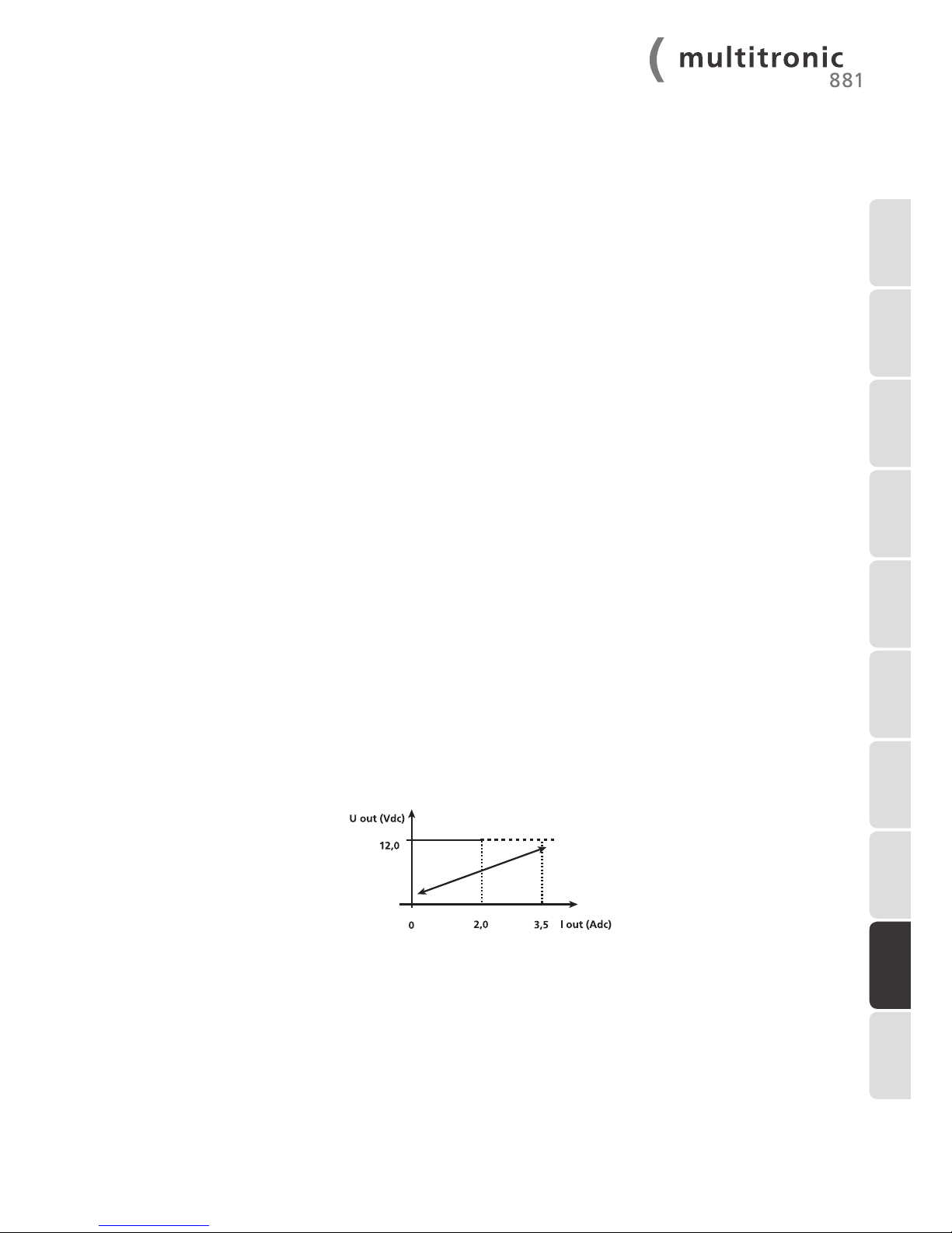
Current limiting: Refer to the characteristic line in the diagram
Efficiency: Type 79 %
Connections: 300 mm x 0.75 mm
2
Dimension: 230 x 25 (29) x 35 mm
Weight: Approx. 350 g. (including cable)
U/I characteristic line:
9.4 FUHR multitronic switching power supply unit
1 INTRODUCTION
2 IMPORTANT
INFORMATION
3 DELIVERY SCOPE
8 TROUBLE-
SHOOTING
4 INSTALLATION
INSTRUCTIONS
5 COMMISSIONING 6 EXTERNAL
CONNECTION
OPTIONS
7 MAINTENANCE
AND CARE
9 TECHNICAL
DATA
10 OPTIONAL
ACCESSORIES
Page 34
34
WWW.FUHR.DE
10 Optional accessories
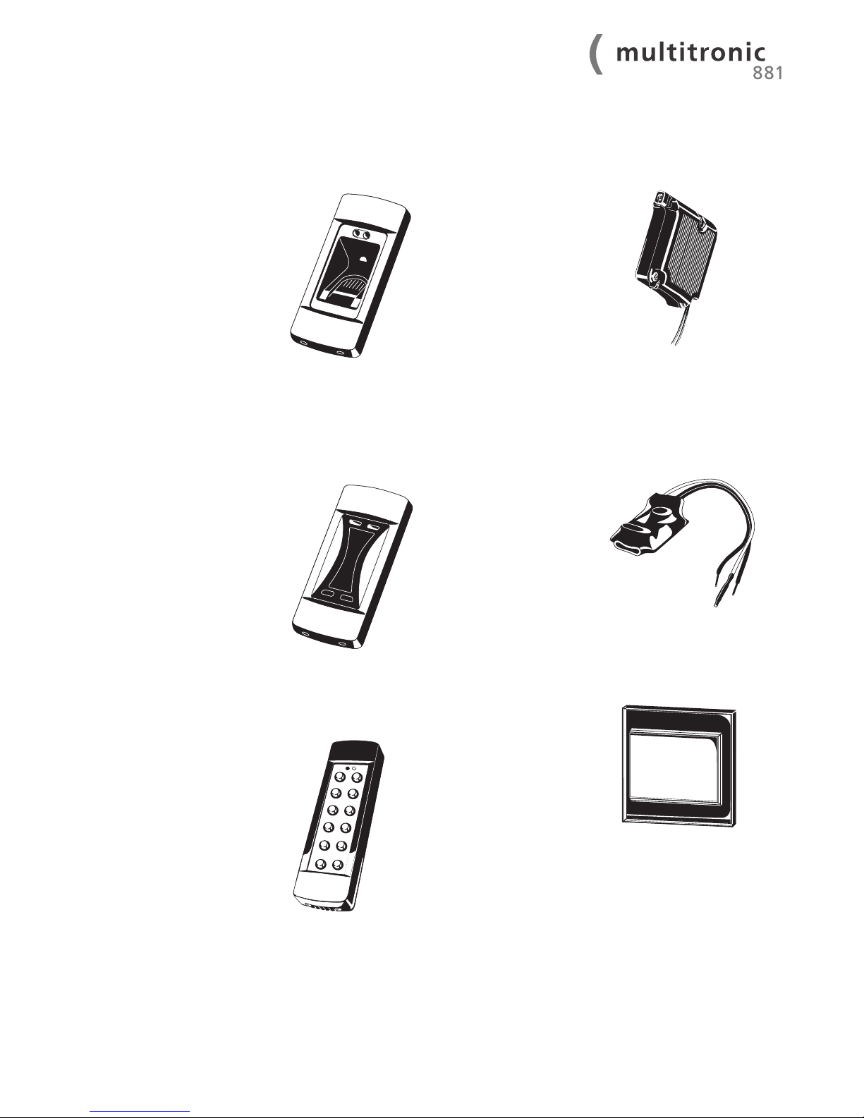
10.1 Radio fingerprint
scanner
Biometric system for convenient, keyless access control. With 2 channel technology, opening impulse via
rolling code process.
Item no. NB366
Item no. NB252N (cover)
Please order the cover separately.
10.2 Radio transponder
reader
For non-contact code transmission of car keys and
transponders to the control
unit. With 2 channel technology, opening impulse via
rolling code process.
Item no. NB403
Item no. NB540 (without
programming/pairing function for car keys)
Item no. NB252N (cover)
Please order the cover separately.
10.3 Radio keypad
For a code transmission by
entering a numeric combination. With 2-channel
technology and an additional radio gong channel.
Opening impulse via rollingcode process.
Item no. NB404
Item no. NB405N (cover)
Please order the cover separately.
10.4 Radio receiver modul
Pluggable onto the motor
drive, compatible with all
FUHR radio control moduls.
A separate control is not
necessary. Connects directly
to the motor drive socket.
2-wire technology between
mains adapter and motor
drive is sufficient. 25 transmitters programmable. For
motor drives with plug-in
device.
Item no. NBFP490
10.5 Built-in transmitter
for intercom systems
For installation in intercom
systems. Sends a signal
to open the door when
powered with a voltage
between 5-24 V AC or
6-32 V DC. With pre-assembled connection cable.
Item no. NZ80123
10.6 Radio push-button
switch
Enables convenient door
opening from the inside
at the touch of a button.
Wireless – can be installed
anywhere. Battery operated.
Silver with glass frame.
Item no. NZ80021AS
Page 35
35
Silver
Stainless
steel
1 INTRODUCTION
2 IMPORTANT
INFORMATION
3 DELIVERY SCOPE8 TROUBLE-
SHOOTING
4 INSTALLATION
INSTRUCTIONS
5 COMMISSIONING 6 EXTERNAL
CONNECTION
OPTIONS
7 MAINTENANCE
AND CARE
10 OPTIONAL
ACCESSORIES
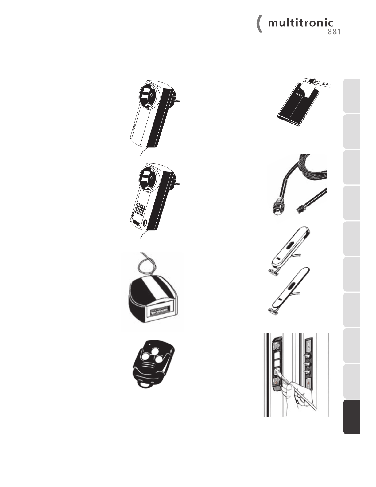
10.7 Power socket radio
receiver
Designed for use with twopin earthed/grounded plugsockets. For triggering existing electrical drive units via
radio key, e.g. garage doors.
Item no. NZ80088
10.8 Plug socket radio
gong
Suitable for Schuko electric
plug sockets. Receives the
signal emitted by radio keypad or radio wall-mounted
switch. Also applicable for
doors in nursery schools.
Item no. NZ80122
10.9 Universal adapter
Optional extra to connect to
existing control units (e.g.
from garage door drive
units).
External power supply necessary (12-24 V AC/DC).
Item no. NZ80023
10.10 Radio keys
Additional radio key with
turquoise buttons.
Item no. NZ80062
10.11 User transponder
Additional user transponder
(3 user transponders are
included in delivery of transponder reader).
Item no. NZ80104
10.12 Indicator LED for
the exterior side of
the door
Can be used optionally as
a visual indicator of the
locking status.
Item no. NZ80067
10.13 Cover for the
control unit with
sliding switch and
connection cable
Enables the manual activation of the day latch function (connection to terminals
11 + 12) or daylatch retaining function (connect to terminals 9 + 10).
Silver
Item no. NZSTZ0265
Stainless steel
Item no. NZSTZ0459
10.14 Contact grease
For contact areas to guarantee connection between the
contact surfaces and tappet
contacts.
Item no. NZ80077
9 TECHNICAL
DATA
Page 36
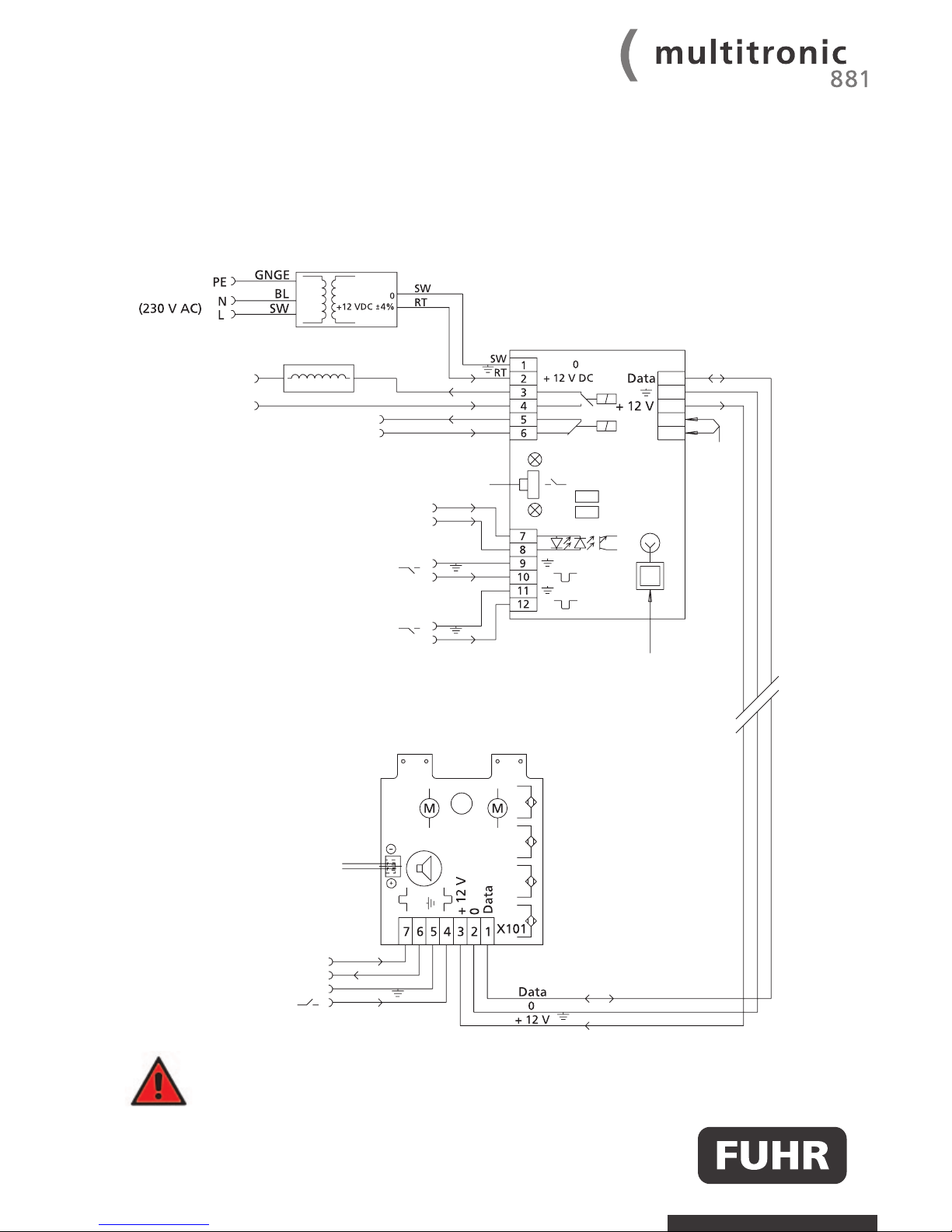
11 Wiring diagram
Note: In order to activate the alarm system function via terminal 16 and 17, both the motor's circuit
board as well as the control unit's circuit board require software release 4.3 or higher.
WWW.FUHR.DE
CARL FUHR GmbH & Co. KG Schlösser und Beschläge
Carl-Fuhr-Straße 12 D-42579 Heiligenhaus
Tel.: +49 2056 592-0 Fax: +49 2056 592-384
www.fuhr.de · [email protected]
Main control with removable
radio receiver and visual
locking indicator
white
brown (black)
green (red)
Electricity and data transmission: via cable or tappet contacts ( )
Removable radio receiver
Terminal 16 & 17: Disconnection
function of access control systems
by alarm system via potential-
free continuous signal
Tune-in button RADIO
DRT Jumper DRT
TGF Jumper TGF
Power supply via switching power supply unit
min. 12 V DC / 3A (residual ripple < 250 mVpp)
GREEN
RED
Mains
green (red)
brown (black)
white
Terminal 7-8: Input (6 ... 12 V AC or 6 ... 24 DC)
For opening impulse and day latch function 1.
Terminal 9-10: Input potential-free:
For opening impulse and day latch retaining function.
The swing door opener function 2 can be activated by
removing jumper DRT.
Terminal 11-12: Input potential-free:
For opening impulses and day-latch function 1.
The day-latch function 2 can be optionally activated by
removing jumper TGF.
Opening impulse 6-12 V AC / 6-24 V DC
Output: 12 V DC (max. 360 mA)
GND
Opening impulse (potential-free)
Electrical swing door
opener (AC/DC)
Alarm output
(opens if dry reed contact is open)
12 V-Output for external
indicator LED
Drive unit control
13
14
15
16
17
 Loading...