

Page 1
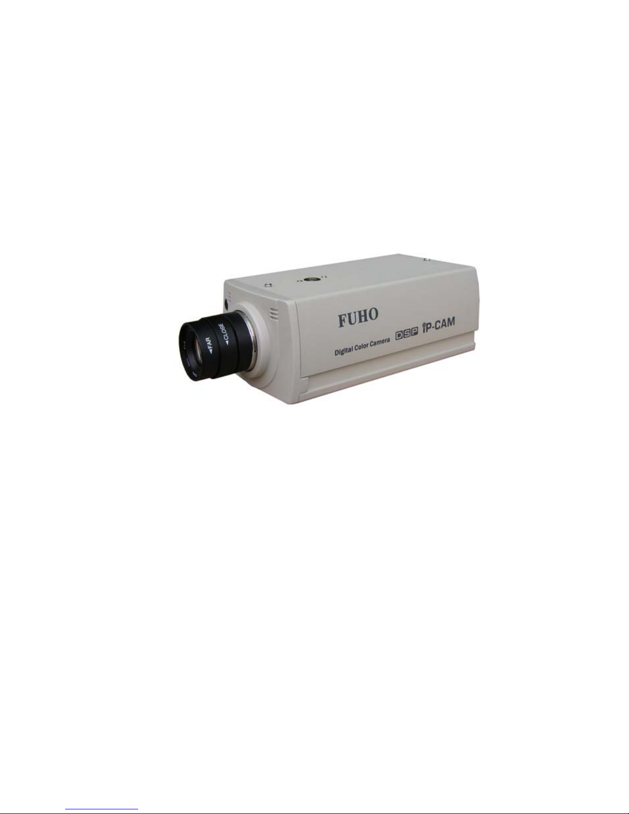
IP901 User’s Manual
Page 1
IP901-IP-CAM
USER MANUAL
Page 2

IP901 User’s Manual
Page 2
Cautions
1. Read this user manual before use
2. Keep this user manual accessible
3. Follow instruction
4. Keep this unit away from cleanser
5. Keep this unit dry in ventilation
6. Give way to ventilation outlet
7. Power cord must be fixed properly
8. To avoid damage, unit must not be stuffed or be splashed with something
9. Do not repair this unit on your own
10. Please contact local dealer for the following condition:
a. Power cord damaged
b. Showered unit
c. Failure in operation
d. Unit dropped or cabinet damaged
11. Repairing components must be approved by original manufacturer.
12. Ground wire of outdoor image source must be well connected to the ground to prevent from
thunder attack
13. Power cord and outdoor image source cable should be detached in case of thunder attack
Warning
Only qualified engineer can detach the cover. There is nothing inside for end users.
Cover must not be removed in case of power on.
Page 3

IP901 User’s Manual
Page 3
CONTENT
1. OUTLINE
1.1 INTRODUCTION ...................................................4
1.2 FEATURE ................................................................5
1.3 ACCESSORY ..........................................................5
1.4 SYSTEM REQUIREMENT ................................... 5
1.5 PANELS ................................................................... 6
1.5.1 FRONT PANEL ....................................................6
1.5.2 REAR PANEL ......................................................6
2. INSTALLATION
2.1 CABLING ................................................................8
2.2 SURVEILLANCE SOFTWARE ............................ 11
2.3 ETHERNET FRAMEWORK & CONNECTION .13
2.3.1 PC TO IP-CAM CONNECTION ........................13
2.3.2 INTRANET CONNECTION ...............................16
3. OPERATION
3.1 LivePlayer SURVEILLANCE SOFTWARE ........19
3.1.1 LivePlay SOFTWARE INTERFACE .................19
3.1.2 LivePlayer INTERFACE SETUP .......................21
3.2 IE BROWSER SETUP CAMERA FUNCTION ..29
3.2.1 Web Server AUTHORIZATION ........................30
3.2.2 Status ...................................................................31
3.2.3 View .......................................................................32
3.2.4 System ....................................................................33
3.2.5 Network .................................................................34
3.2.6 Image .....................................................................35
3.2.7 User ........................................................................35
3.2.8 Alert .......................................................................36
3.2.9 Factory Default Function .....................................38
3.2.10 Restart Function .................................................38
3.2.11 Upgrade ...............................................................39
4. ELSE
4.1 SPECIFICATIONS .................................................40
Page 4
IP901 User’s Manual
Page 4
1. OUTLINE
IP-CAM is a low cost provision of network surveillance facility which transmits images on
network to remote PC in format of compression technology. Monitoring, storage and recognition
on line are provided by IP-CAM. Image transmission remains the same quality on both ends of
server site and remote site. Single image source can be transmitted to multi ports saving lots of
cabling overhead.
1.1 INTRODUCTION
Dual compression technology JPEG & MPEG-4, remote site operator can access to the server
site via IE browser to secure personal safeguard and property. IP-CAM works with existing
digital network transmission system. LivePlayer software provides functions of live monitoring,
monitoring setup conditions & motion/schedule recording.
Page 5

IP901 User’s Manual
Page 5
1.2 FEATURE
; Image & audio transmission via network
; Dynamic IP & static IP support
; Dual compression technology JPEG & MPEG-4
; Digital alarm I/O
; RS-485 for PTZ control
; LivePlayer client software
; Built in motion detection & recording functions
; IE browser remote monitoring & setup support
; Firmware upgrade via IE browser on line
1.3 ACCESSORY
[1] . IP-CAM
[2] . CD ROM
Remarks
[1] . Please contact local dealer in case of accessory shortage
[2] . IP-CAM may be damaged & warranty void in use of other power adaptors
1.4 SYSTEM REQUIREMENT
; Pentium4 or above
; Windows 2000/XP OS
; Protocol comply to 802.11 or ADSL network
; Microsoft Internet Explorer 6.0 or above
; Microsoft Codec Installation Package for Windows Media Player 6.4 or above
( http://www.microsoft.com/windows/windowsmedia/format/codecdownload.aspx )
Page 6
IP901 User’s Manual
Page 6
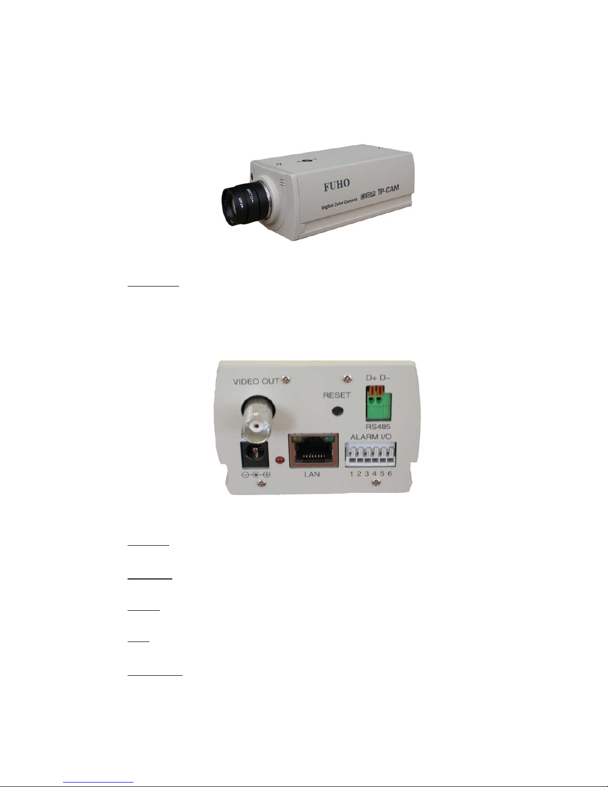
1.5 PANELS
1.5.1 FRONT PANEL
Microphone
Build-in Microphone
1.5.2 REAR PANEL
DC +12V
Power input port receives 12VDC power
Video Out
Video output port provides images to monitor or recording devices
RS-485
RS-485 control port for PTZ control
LAN
RJ-45 10/100 Based-T Ethernet transmission port
Reset Button
Press this button to restart
Page 7

IP901 User’s Manual
Page 7
ALARM I/O
Alarm input/output port two sets for digital sensor input one set for digital alarm output
Definition of the pins
1. +12VDC
2. digital sensor input #1; Hi active
3. digital sensor # 2; Hi active
4. GND。
5. digital output out
6. digital output in
caution: pin #2 & pin #3 are individual input ports Hi active input voltage rated 12VDC
pin #5 & pin #6 are the same output port normal open alarm close
POWER LED
Power indicator power on indicator red
LAN LED
Network indicator LED ON LAN working
Page 8
IP901 User’s Manual
Page 8
2. INSTALLATION
2.1 CABLING
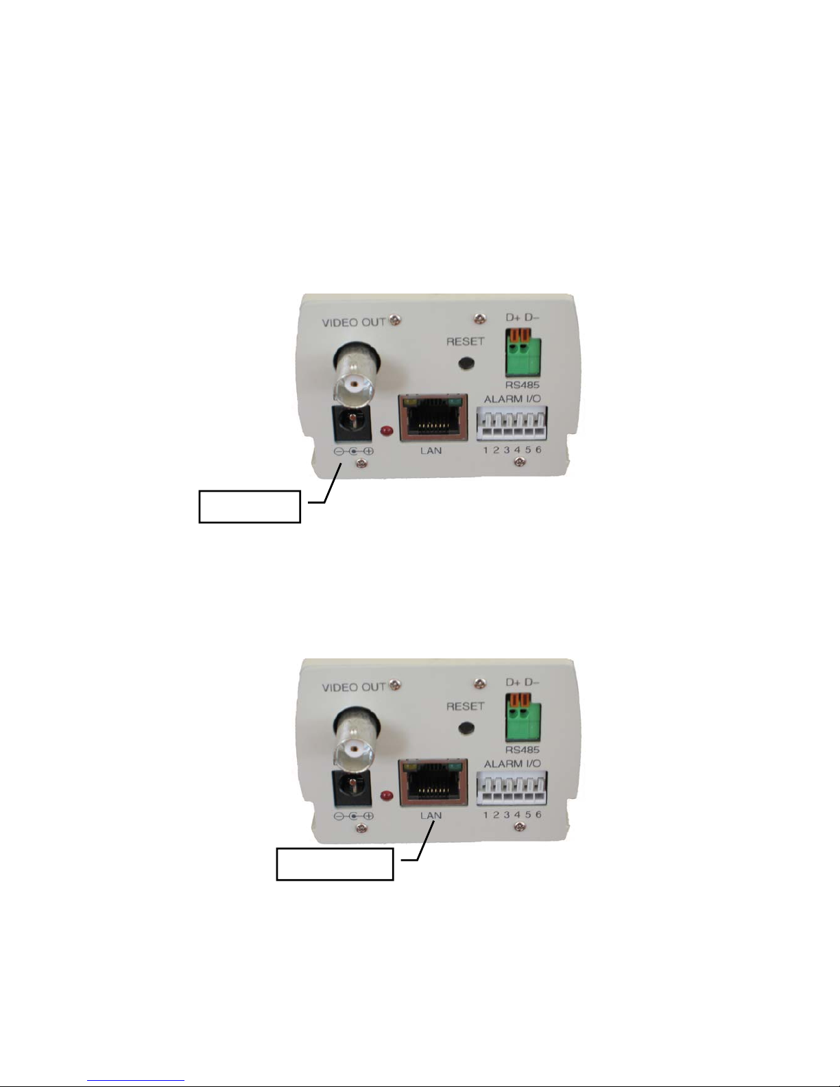
1. Power Input
Plug in the power adaptor which supplies +12VDC. IP-CAM could be damaged of
improper voltage input. Power LED turns to red in five seconds IP-CAM system
activated.
2. Plug in Ethernet Cable
Plug the cable in the Ethernet port with “LAN" mark for Ethernet connection.
Ethernet port
Power Input
Page 9
IP901 User’s Manual
Page 9
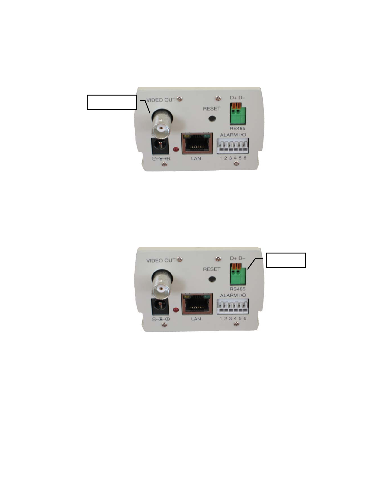
3. Video Output
“VIDEO OUTPUT" is to be connected to CCTV monitor for live monitoring. The
video output format is 1 Vp-p Composite Video Signal, 75 Ω
4. RS-485 Connection
RS-485 --- Pan Tilt Control Port. User can setup pan tilt control on IE browser.
Please keep alert on the polarity D+ & D- of RS-485 port.
RS-485
Video Output
Page 10
IP901 User’s Manual
Page 10
2.2 SURVEILLANCE SOFTWARE
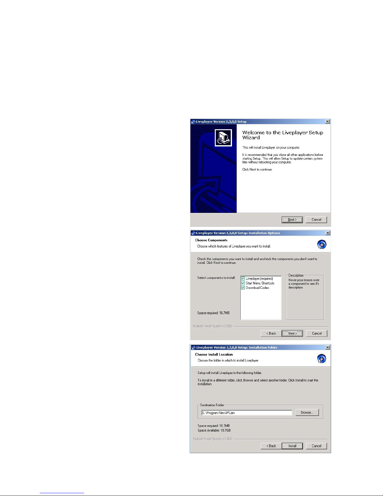
Please use the enclosed CD ROM to install the software
1. Put the CD ROM in CD drive
2. Execute the file “Liveplayer_Setup.exe” to start installation. This software promptly
supports OS of English, traditional Chinese & simplified Chinese.
3. Click “Next” to initiate software
installation
4. Click “Next” in the dialog of
“Choose Components”
5. Choose the default directory
Page 11
IP901 User’s Manual
Page 11
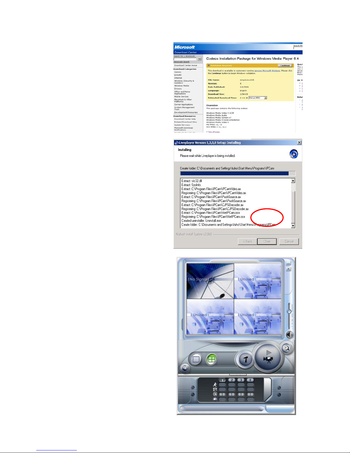
6. Execute Codec Installation Package
to download software via internet
7. Click “Close” upon installation
finished
8. Click “start” Δprogram files”
ΔIPCam”ΔLivePlayer”
Page 12
IP901 User’s Manual
Page 12
2.3 ETHERNET FRAMEWORK & CONNECTION
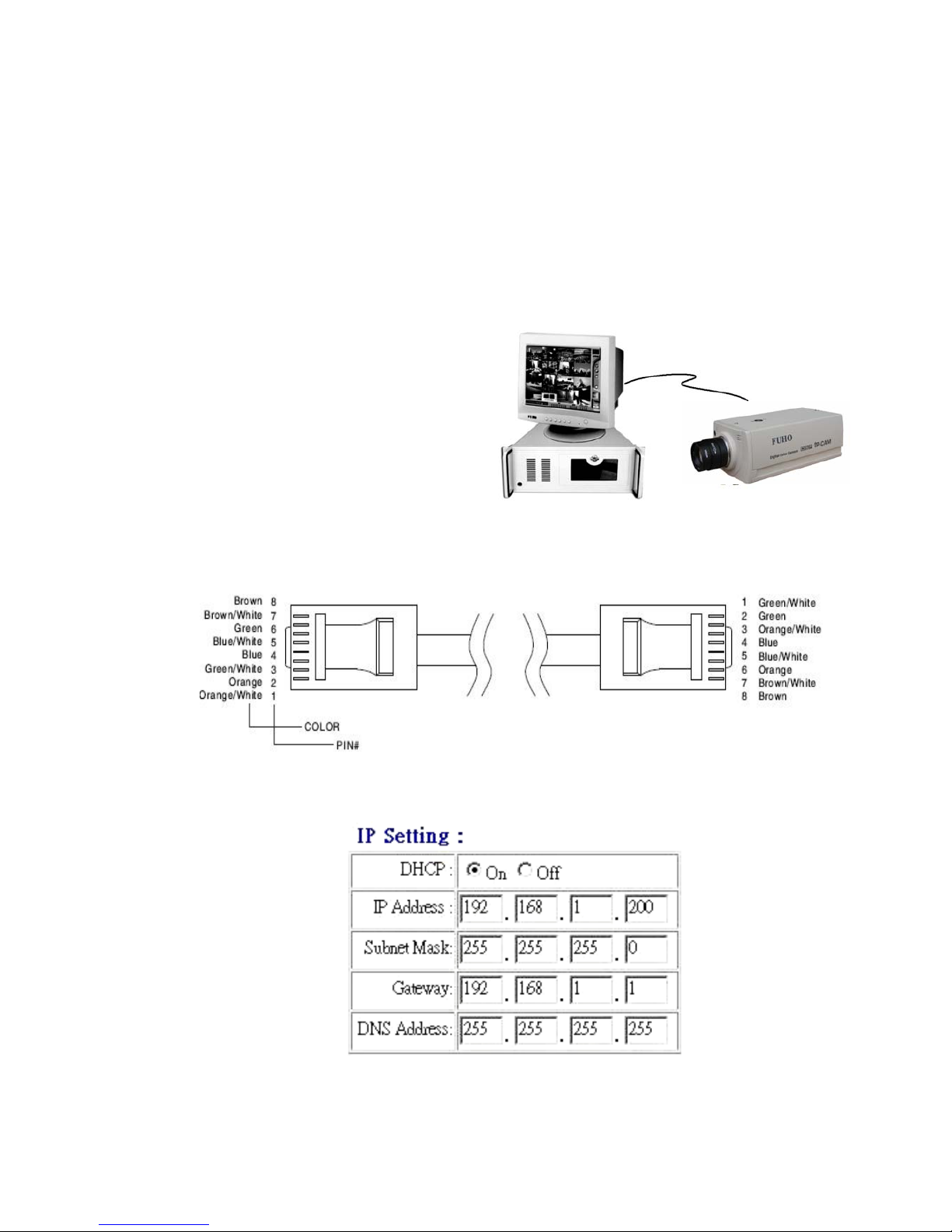
IP-CAM can be connected to DSL modem or hub. IP-CAM will start detecting DHCP
protocol upon power input. IP-CAM enables DHCP protocol to work with NAT IP address when
NAT router in use. Default IP address 192.168.1.200 starts working when NAT router not in use.
Suppose 192.168.1.200 has been occupied by other device. Other device must be shut down
beforehand until IP-CAM finishes IP setup.
2.3.1 PC TO IP-CAM CONNECTION
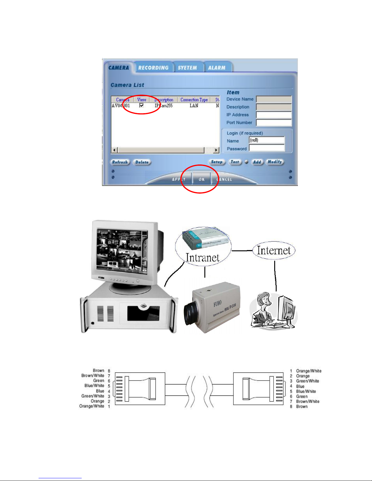
1. Use Cat5 Cross-over Cable to connect PC
Cat5 Cross-over Cable (EIA 568A/B )layout & definition
2. Video server default setup as follows
Page 13
IP901 User’s Manual
Page 13
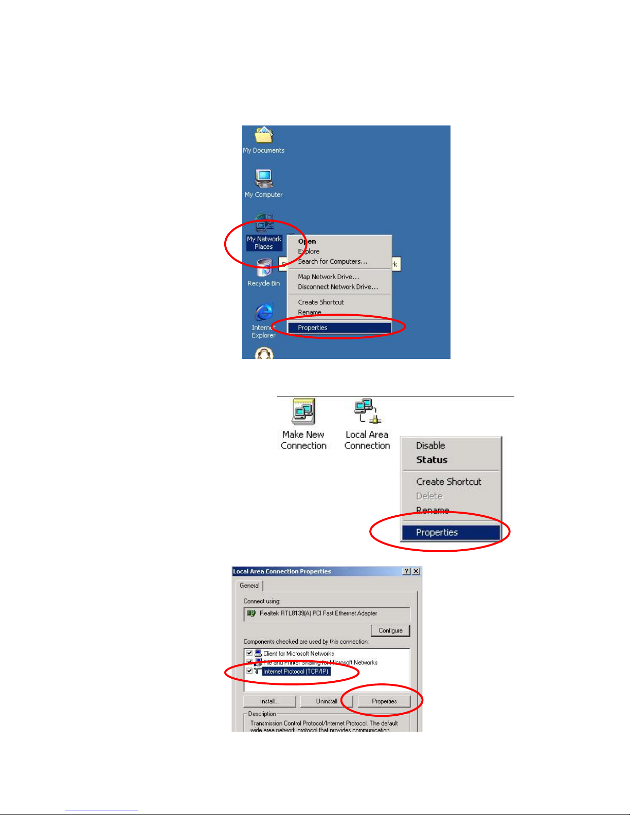
3. Setup IP address of PC’s LAN card same as IP-CAM’s domain.
In condition of W indowns-2000/XP OS
a. Select “My Network Places” by clicking mouse on the right.
Click “properties” accordingly.
b. Select “Local Area Connection” by clicking mouse on the right.
Click “Properties” accordingly.
c. Select ”TCP/IP” and click “Properties”
Page 14
IP901 User’s Manual
Page 14
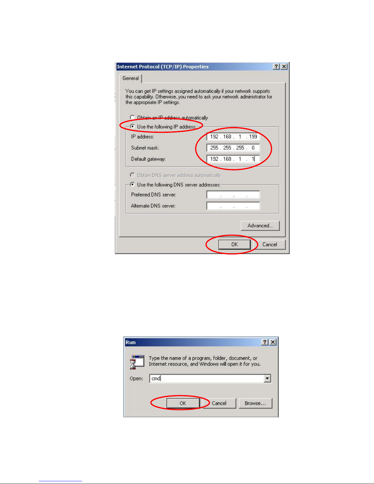
d. Select “Use the following IP address” to input IP address, Subnet mask and
Default gateway. Click “OK” accordingly.
4. Follow the following procedure to make sure IP address correct.
a. Click “START” ΔRUN” and input “cmd”.
Click “OK”.
Page 15
IP901 User’s Manual
Page 15
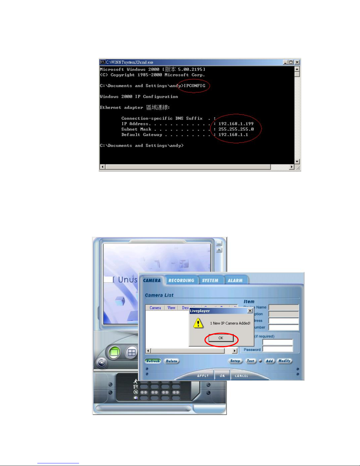
b. Enter DOS and input “ipconfig”. Click “enter” to inspect IP address, Subnet
mask and Default gateway.
Please logout and login if IP incorrect.
5. Connection
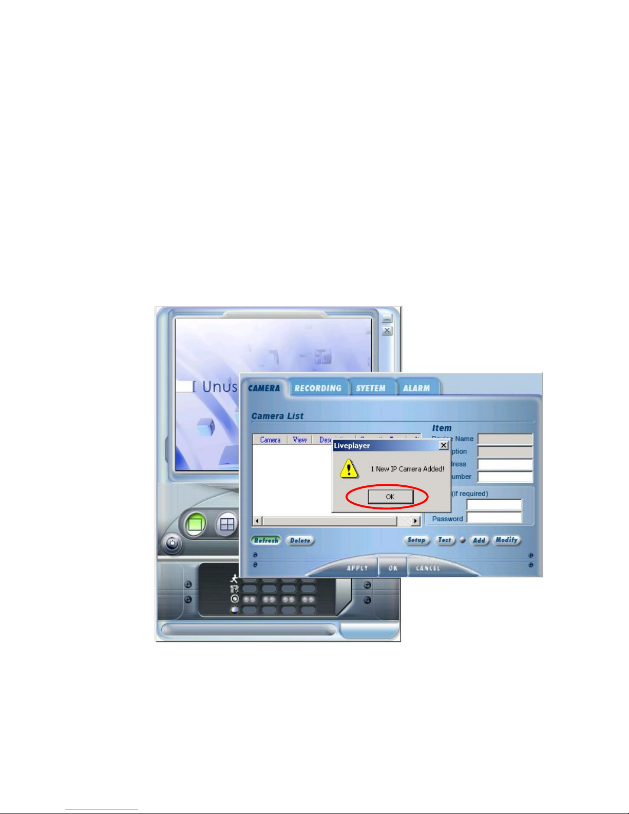
a. Execute the client software LivePlayer. Click “Setup” and “Refresh” to search
IP-CAM. It takes time to search the IP-CAM. Please be patient. Alert dialog
pops up upon video server found. Please review 3.1.2 for details.
Page 16
IP901 User’s Manual
Page 16
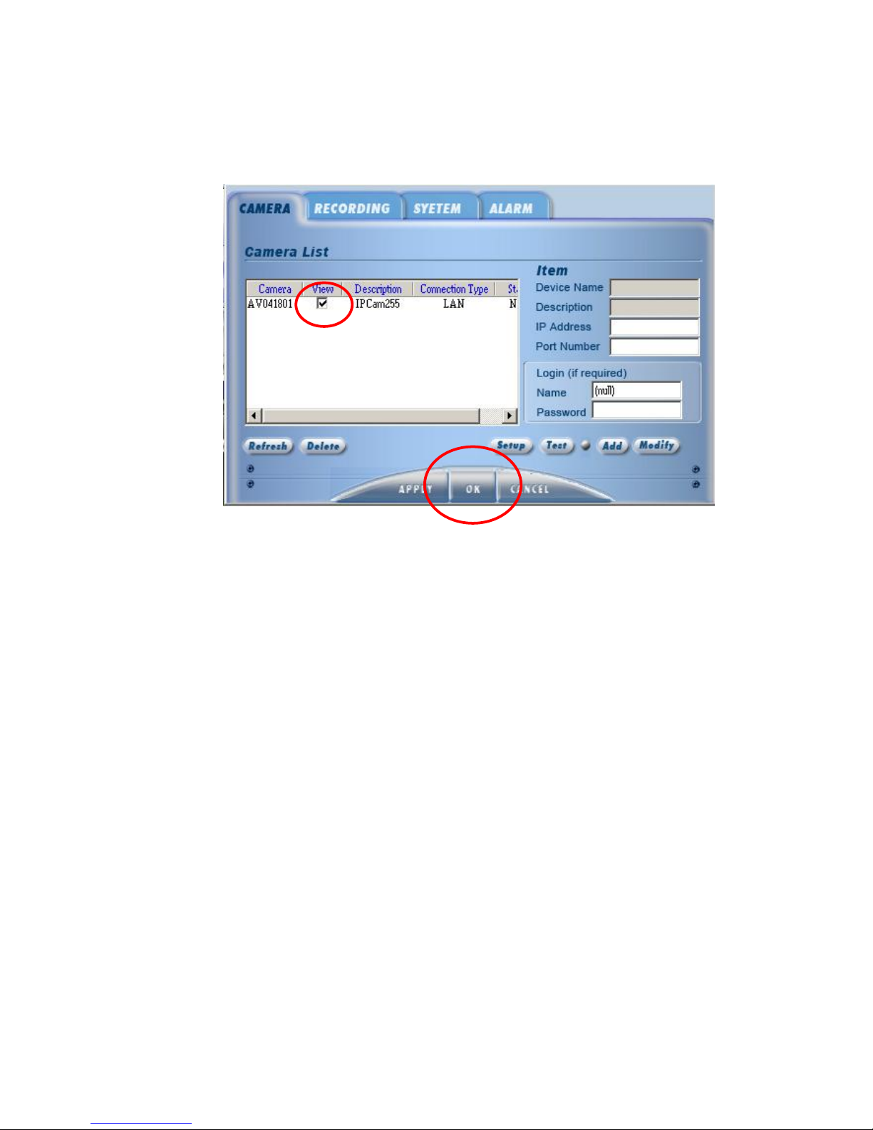
b. Click “View” and “OK” to start connection.
2.3.2 INTRANET CONNECTION
1. Cat 5 cable must be used in condition of connection via router, DSL modem and hub.
Page 17
IP901 User’s Manual
Page 17
2. Please make sure PC and video server same domain.
3. IP-CAM detects DHCP when system starts working. IP-CAM enables DHCP protocol to
accept IP address from NAT when NAT router detected. Default IP address becomes
192.168.1.200 when NAT router not detected. Suppose there is an IP address
192.168.1.200 on internet. This device must be turned off prior to IP-CAM renew the IP
setup.
4. Connection
a. Execute client software “LivePlayer”. Click “Setup” and “Refresh” to start
IP-CAM search. Please be patient for waiting IP-CAM search. Click “OK” by
the time video server detected. Please review 3.1.2 for details.
Page 18
IP901 User’s Manual
Page 18
b. Tick the item “View” and click “OK” to start connection.
Page 19
IP901 User’s Manual
Page 19
3. OPERATION
3.1 LivePlayer SURVEILLANCE SOFTWARE
IP-CAM provides LivePlay client software. Four units of IP-CAM can be monitored and
managed at the same moment.
3.1.1 LivePlay SOFTWARE INTERFACE
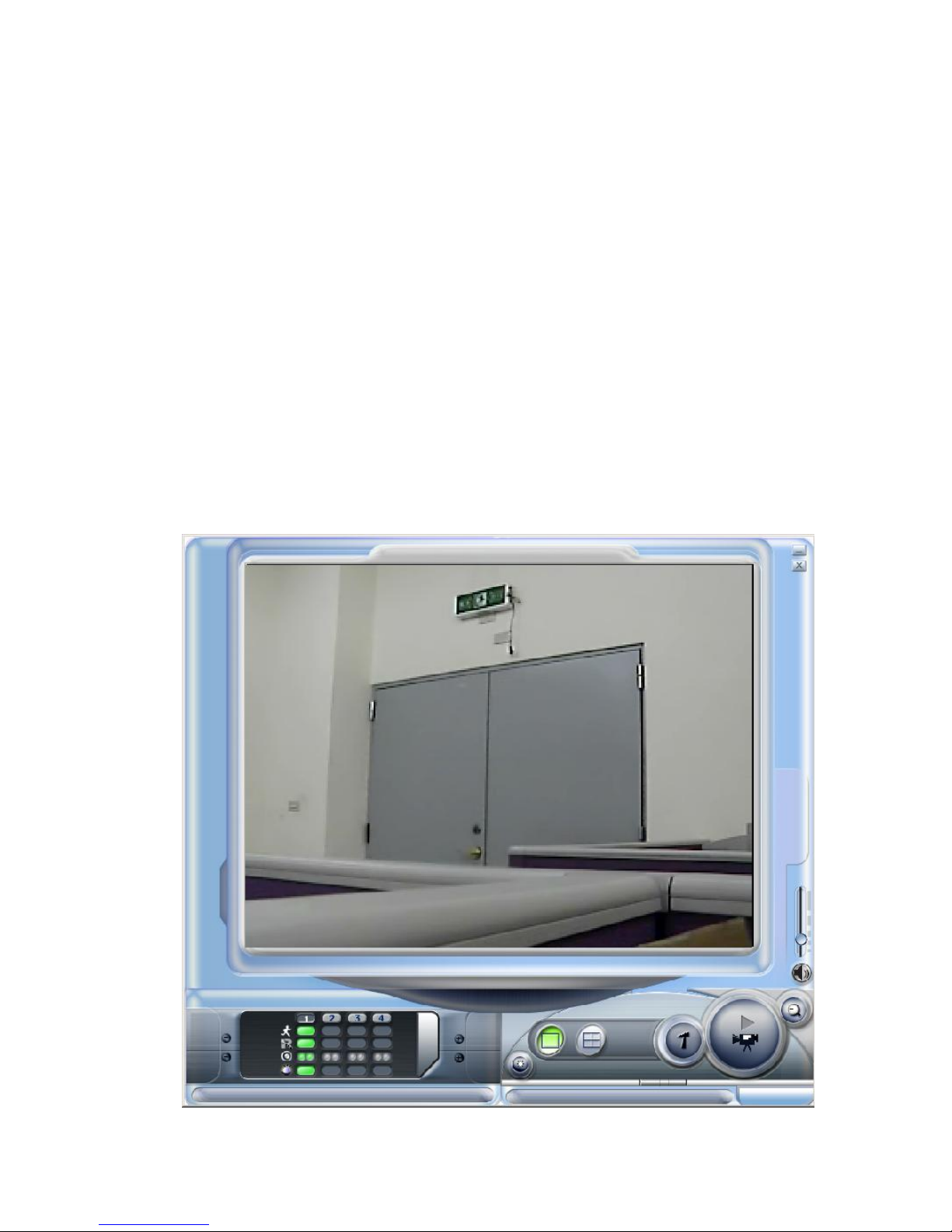
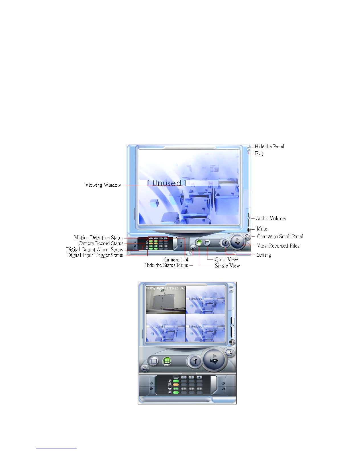
1. LivePlay icon comes up on the desktop after installation. Double clicks on the mouse to
activate LivePlay software. Screen shot and control panel displays as follows:
2. Click “Change to Small Panel” for small size panel.
Page 20

IP901 User’s Manual
Page 20
3. Definition of buttons in the control panel
Exit
Exit LivePlayer
Hide the Panel
Minimize LivePlayer
Quad View
Viewing four channels at the same time
Single view
Viewing single channel
Setting
Entering setup menu to setup internet server, recording, system configuration,
alarm……
View recorded files
Click this button to execute the folder in explorer. Default directory can be
found C:\Program files\IPCam. Recorded files can be found there.
Audio volume
PC’s Sound Card Volume Adjustment
Can monitor the sound at the remote site.
Mute
Mute the sound of sound card.
Change to big panel/change to small panel
Change the size of the panel.
Hide the status menu
Hide the channel selection and alarm status to clarify the screen shot.
Camera 1-4
Inspect the intended channel in single channel status. Input audio in quad status.
motion detection status
Motion Detection Indicator
IP-CAM gives alert when motion detected.
Camera record status
Recording Indicator
PC keeps writing video files in the hard drive.
Digital input trigger status
Digital Sensor Input Indicator
Indicator of Digital Input
Left --- Port # 1
Right --- Port # 2
Video Server comes with two digital input ports to receive alert from sensor.
Digital output alarm status
Digital Alarm Output Indicator
Indicator gives alert when IP-CAM delivers digital output.
Page 21
IP901 User’s Manual
Page 21
3.1.2 LivePlayer INTERFACE SETUP
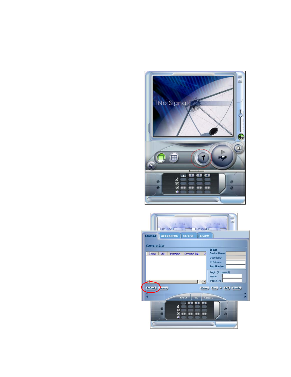
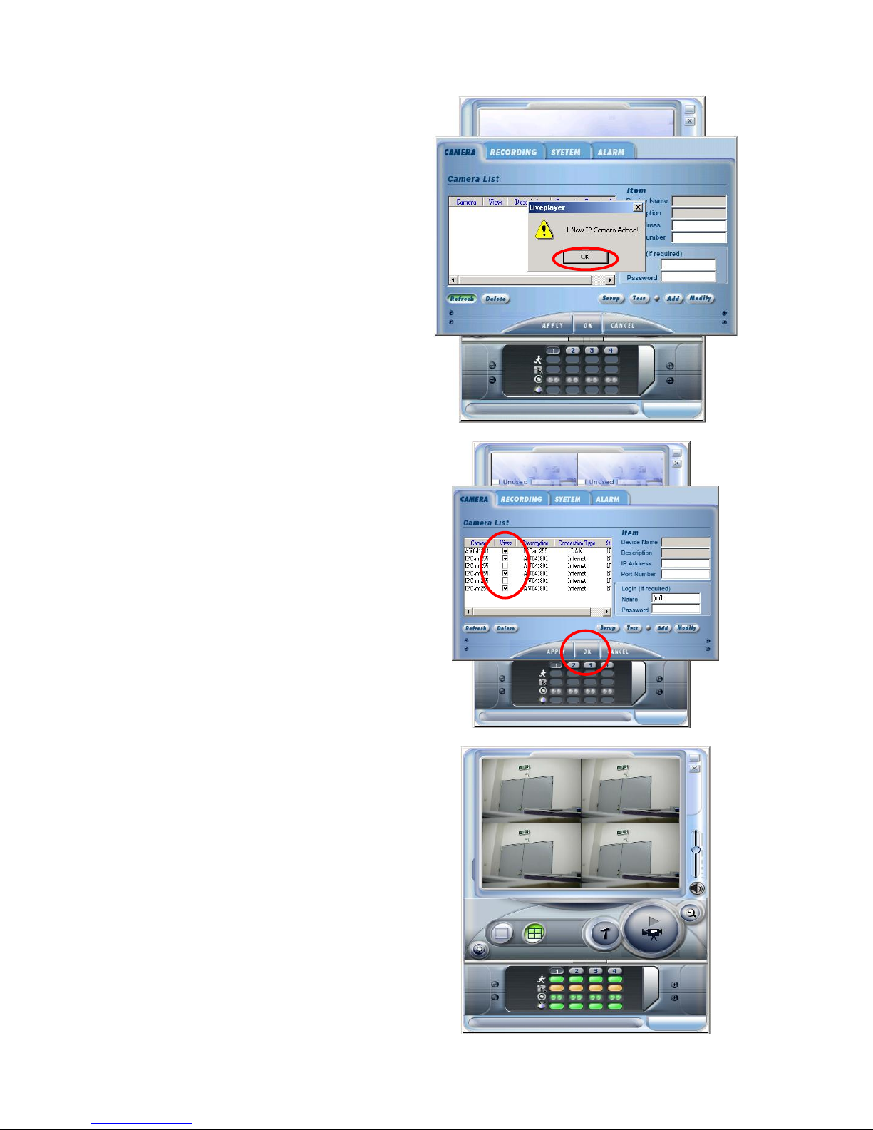
1. Refresh
Refresh function makes installation user-friendly.
a. Click “Setting” to activate
LivePlayer software.
b. Enter “Camera” setup mode.
c. Click ”Refresh” to detect NAT
router and to add camera status in
the list.
Page 22
IP901 User’s Manual
Page 22
d. LivePlayer tells quantity of
camera being added.
e. Click OK
f. Tick up the camera items and
click OK
g. Camera image comes up to the
screen display
Page 23
IP901 User’s Manual
Page 23
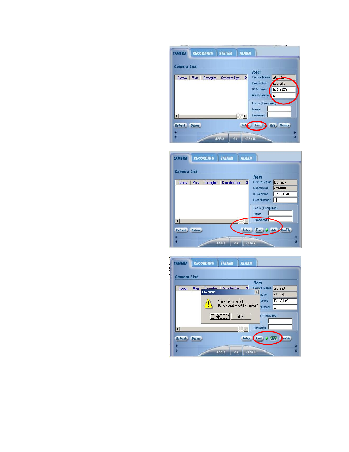
2. Add New Camera
a. Fill in IP address to add up a new
camera
b. Click “Test” to make sure
camera on line
c. Camera name and description
will be seen and test indicator green
in condition of well connected.
Test indicator red in condition of
camera disconnected.
d. Click “Add” to add the new
camera to the list. Software will
search the cameras in the list upon
next activation.
Page 24
IP901 User’s Manual
Page 24
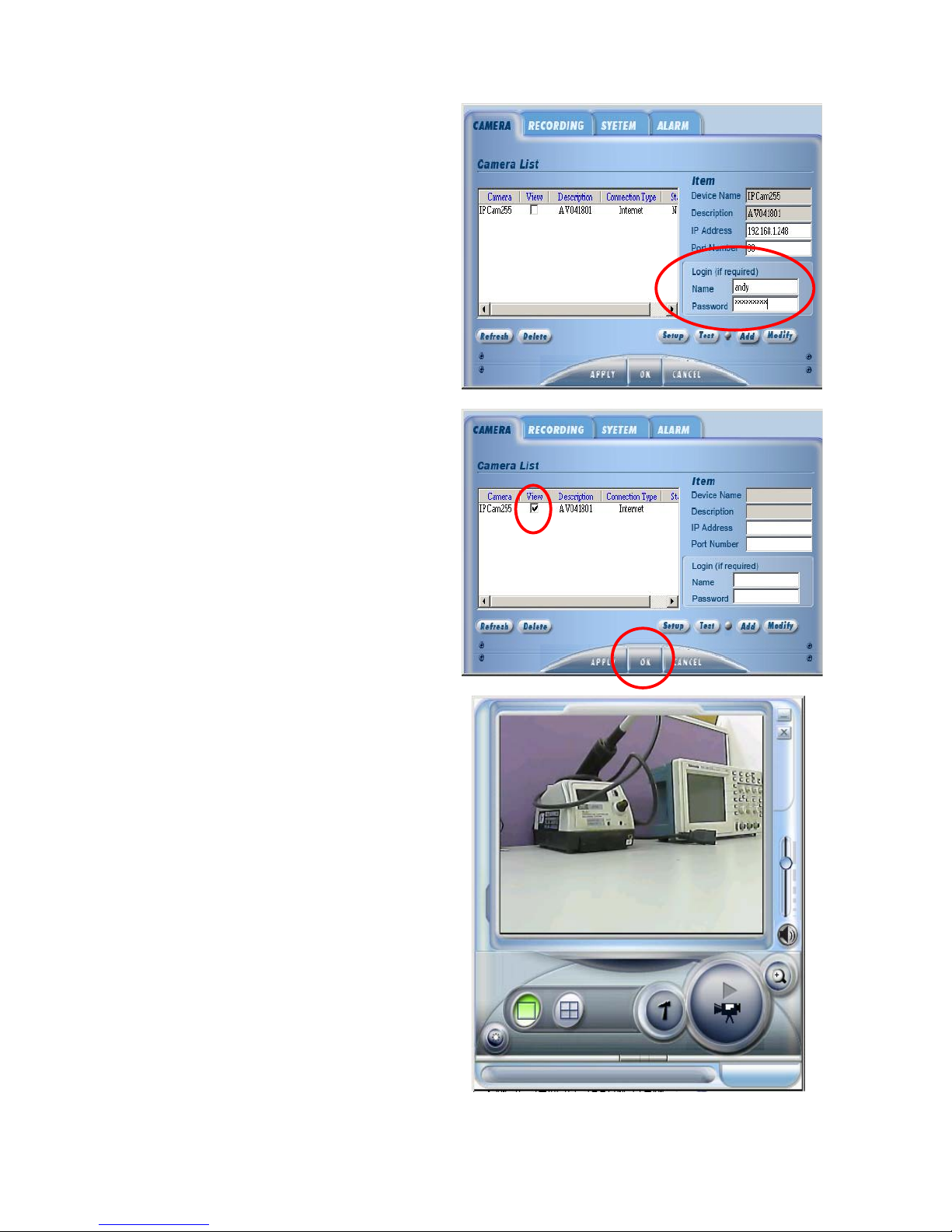
e. If your router or your server
requires Name and Password.
Name and Password must be given.
Click “Modify”.
f. Tick up “View” item, click
“APPLY” and click “OK”.
g. Back to LivePlayer screen
display.
Page 25
IP901 User’s Manual
Page 25
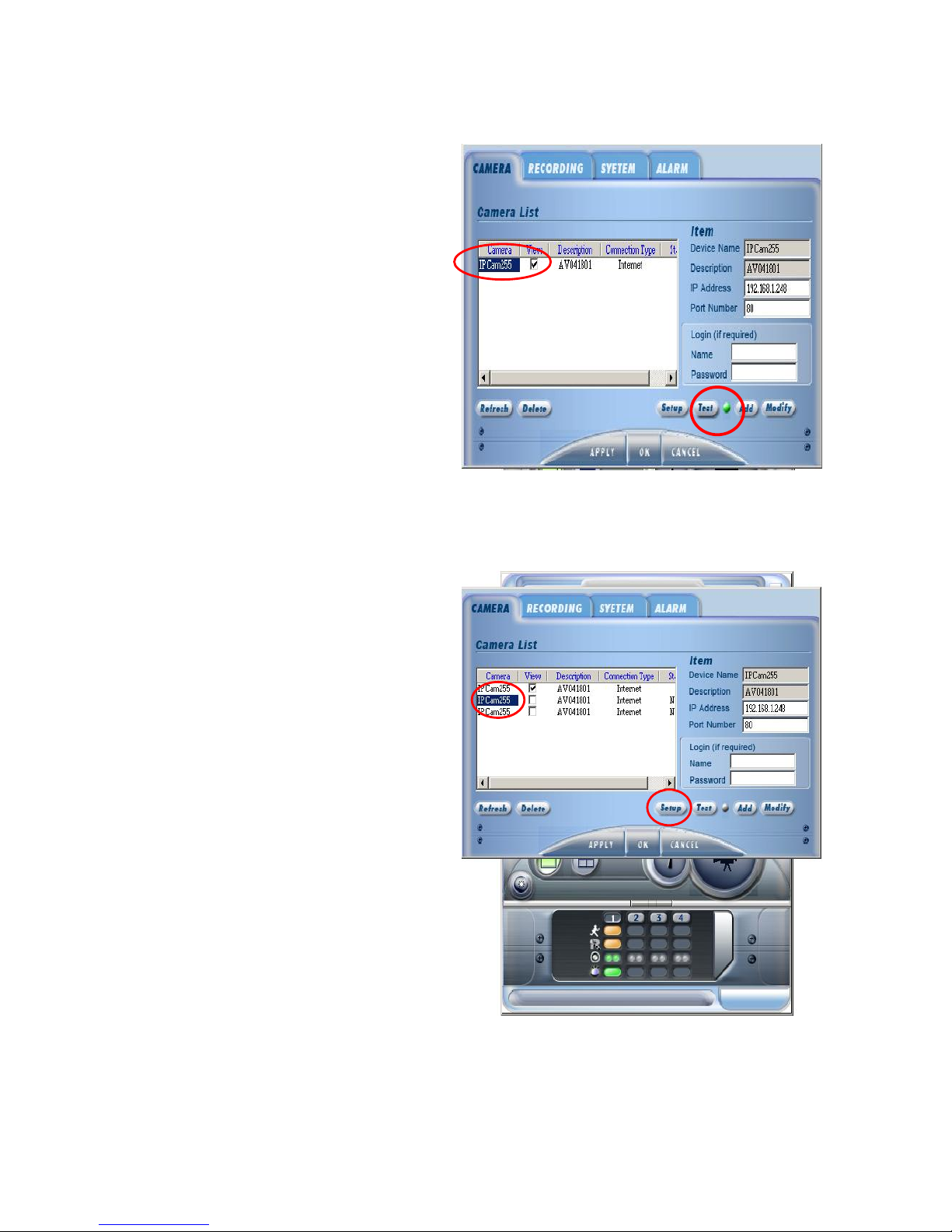
3. Test on Camera Connection
a. Find a camera in the list.
b. Click “Test” to make sure camera
on line.
c. Camera name and description
will be seen and test indicator green
in condition of well connected.
Test indicator red in condition of
camera disconnected.
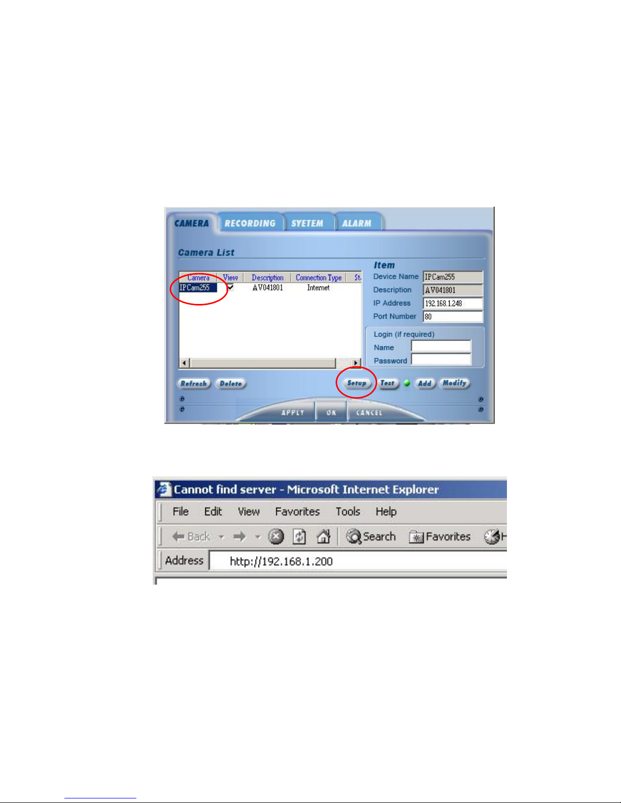
4. Setup in IE Browser
a. Click camera name in the list
b. Click “Setup”.
c. IE browser must be executed.
Page 26
IP901 User’s Manual
Page 26
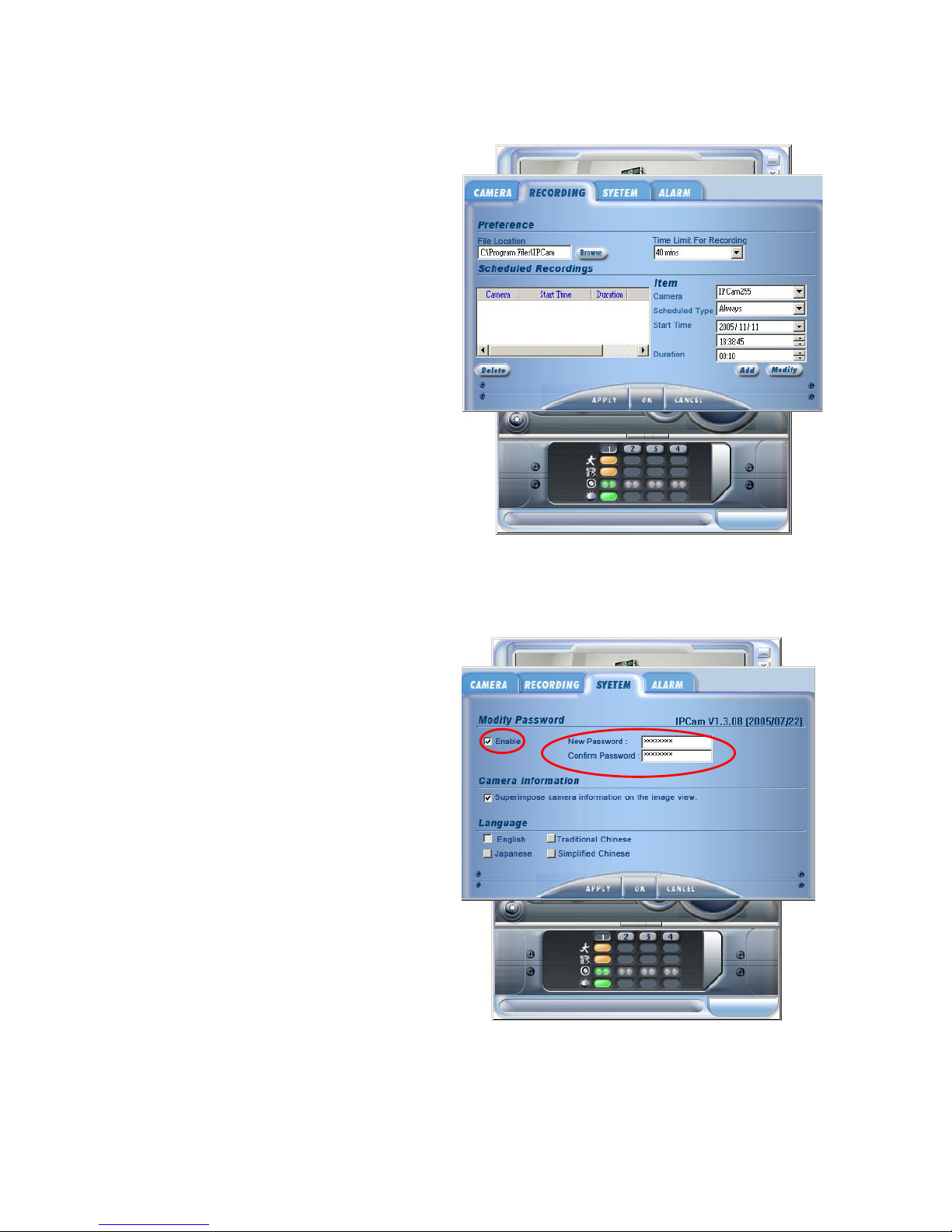
5. Recording Setup
a. Browse
Setup the location for saved video
files.
b. Time Limit For Recording
Setup recording time for a video
file. File name will be changed
upon time up.
c. Scheduled Recordings
Users can choose a camera to setup
its Scheduled Type, Start Time and
Duration.
6. LivePlayer Password Setup
a. Click “SYSTEM” to enter system
setup mode.
b. Tick up “Enable” to start
password setup.
Password can be a single letter or
digit up to eight letters or digits.
Users must keep password firmly in
mind.
Page 27
IP901 User’s Manual
Page 27
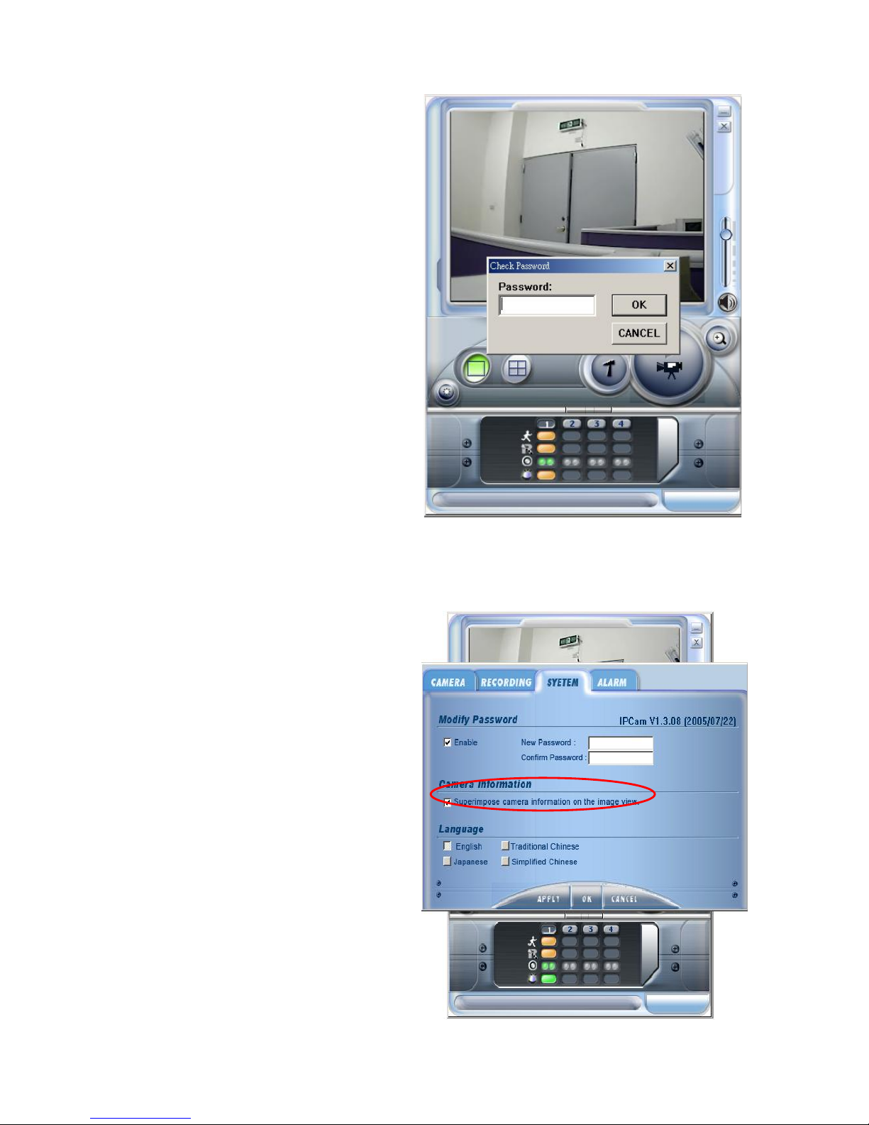
c. Password request pops out before
entering setup mode. Input
password to enter the system.
7. Superimpose camera information on the image view
a. Tick “Superimpose camera
information on the image view” to
input some information on the
imge.
Page 28
IP901 User’s Manual
Page 28
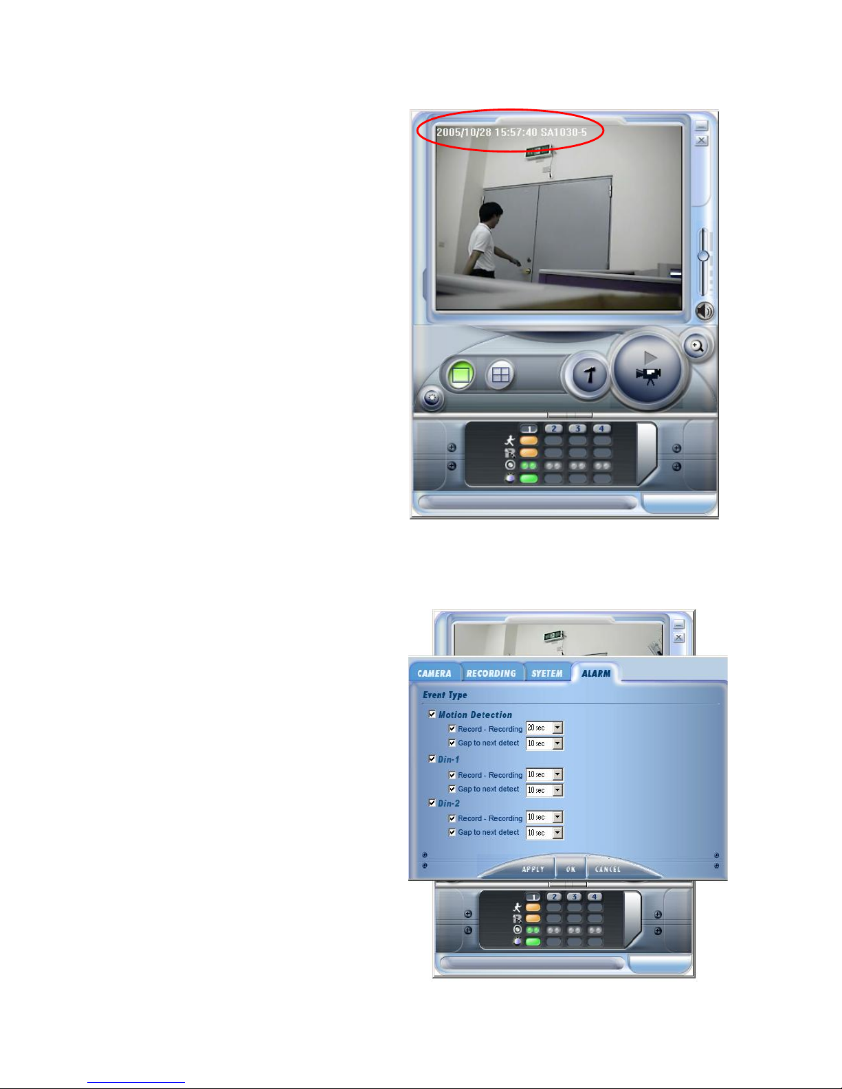
b. Click “Superimpose camera
information on the image view” in
the live mode to show time and
date.
8. Alarm Setup
a. Click “Alarm” to enter alarm
setup.
b. There are two event types.
One is motion detection the other
Is Din. We can setup event
type in alarm setup mode.
Page 29
IP901 User’s Manual
Page 29
3.2 IE BROWSER SETUP CAMERA FUNCTION
System manager can setup hardware via Goahead web server interface. Users must install
LivePlayer to modify device setup via IE browser.
Execute IE browser to input camera IP address or enter camera setup to click “CAMERA".
Both are used to modify camera setup.
Please execute “Restart" function before leaving.
Page 30
IP901 User’s Manual
Page 30
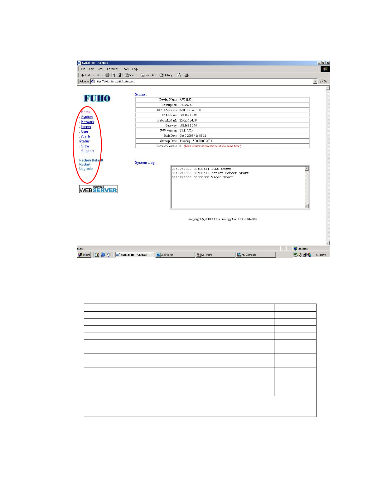
The interface menu includes --- System, Network, Image, User, Alerts, States, View and
Support
3.2.1 Web Server AUTHORIZATION
Different users have different limit on the web pages. Please read 3.2.7for detils.
Page Name Administrator View’s User Config’s User Everyone
System YES NO YES NO
Network YES NO YES NO
Images YES NO YES NO
User YES NO NO NO
Alerts YES NO YES NO
Status YES YES YES YES
View YES YES YES YES*
Support YES YES YES YES
Factory Default YES NO YES NO
Restart YES NO YES NO
Upgrade YES NO YES NO
(1) YES stands for positive. NO stands for negative.
(2) * is the mark for everyone in User Access option. If setup “Only users in database”
only User Database person can operate the page.
Sub menu
Page 31
IP901 User’s Manual
Page 31
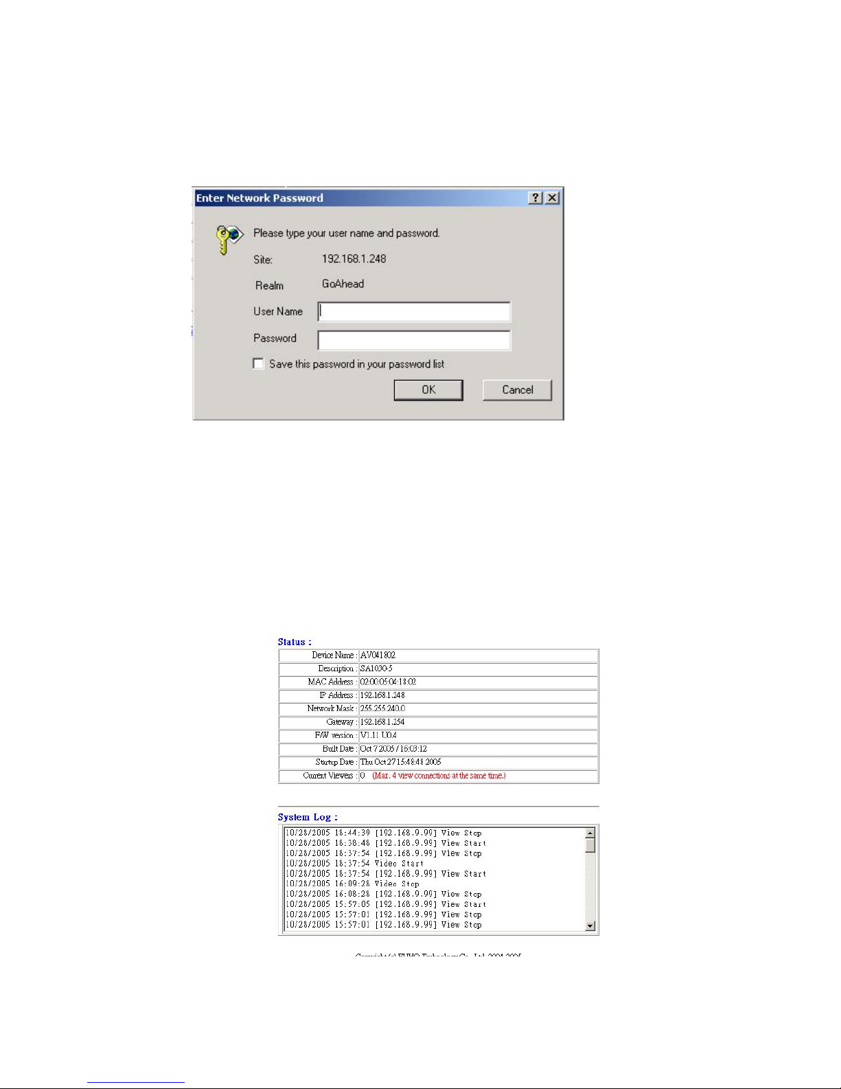
Default User Name & Password
User Name:admin
Password:passwd
User Name and Password can be changed at the first time. User name and Password
must be kept carefully in mind. Tick “Save this password in your password list”. Password
will be save in the remote site PC.
3.2.2 Status
Status includes device name, description, MAC address, IP address, Network Mask, Gateway,
Firmware Version, Built Date, Setup Date, Current Viewers.
Page 32
IP901 User’s Manual
Page 32
3.2.3 View
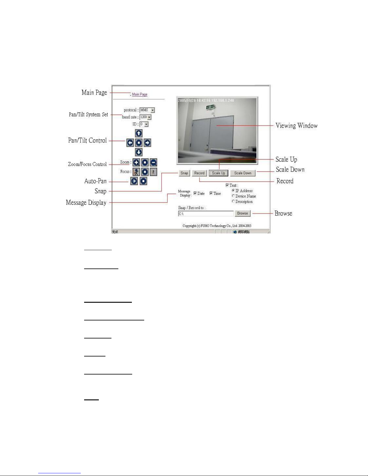
View enables users to monitor camera. Provision of View: Scale Up, Scale Down, Record,
Snap……
Main Page
Click “Main Page" for previous page.
Pan/Tilt Set
Click down pull option of protocol to choose Fum-MMS or Pelco-D. Choose
correct baud rate and ID. Connect Pan/Tilt and video server via RS-485 control
port.
Pan/Tilt Control
Click “Up/Down/Left/Right/Stop” to control Pan/Tilt.
Zoom/Focus Control
Click “Zoom In/Zoom Out/Stop” to control zoom lens.
Auto Pan
Pan/Tilt auto scanning feature.
Browse
System saves the files in C:\ as default directory.
Message Display
Tick “Time” & “Date” for time & date display. Tick “Text” for other display of
“IP Address”, “Device Name” & “Description”.
Snap
Please be aware of the directory of saving files prior to snap feature executed.
System generates file name promptly. Format of the file is .Bmp.
Page 33
IP901 User’s Manual
Page 33
Record
Please remember the directory before record button executed. Record button
will become stop button soon as recording starts. Filename will be generated to
device name plus system time. Asf is the format of the file.
Scale Up
Amplify the picture
Scale Down
Minimize the picture
3.2.4 System
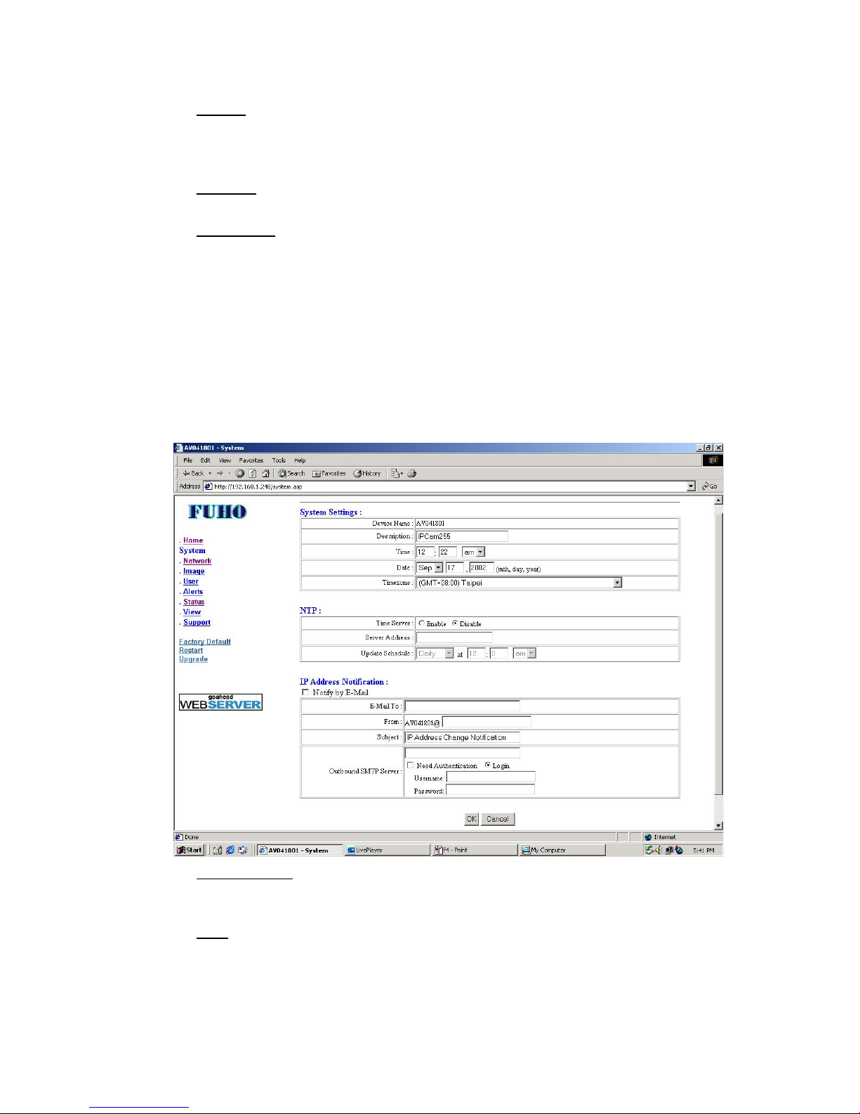
Prior to system setup, User Name and Password are requested.
System provides administrator with amendment on camera information, NTP protocol,
IPaddress, email alert. Please click ok upon amendment finished.
System Settings
System settings are time, date and area. Device name is not a setting for
administrator.
NTP
NTP makes time rectification possible via time server. Time rectification can be
pre-scheduled through local time server. NTP time server as follows:
time.nist.gov
time-A.timefreq.bldrdoc.gov
Page 34
IP901 User’s Manual
Page 34
tick.stdtime.gov.tw prefer
time.stdtime.gov.tw prefer
clock.stdtime.gov.tw
IP Address Notification
Tick “Notify by E-Mail” and input email information. Video server will notify
users IP address change by email.
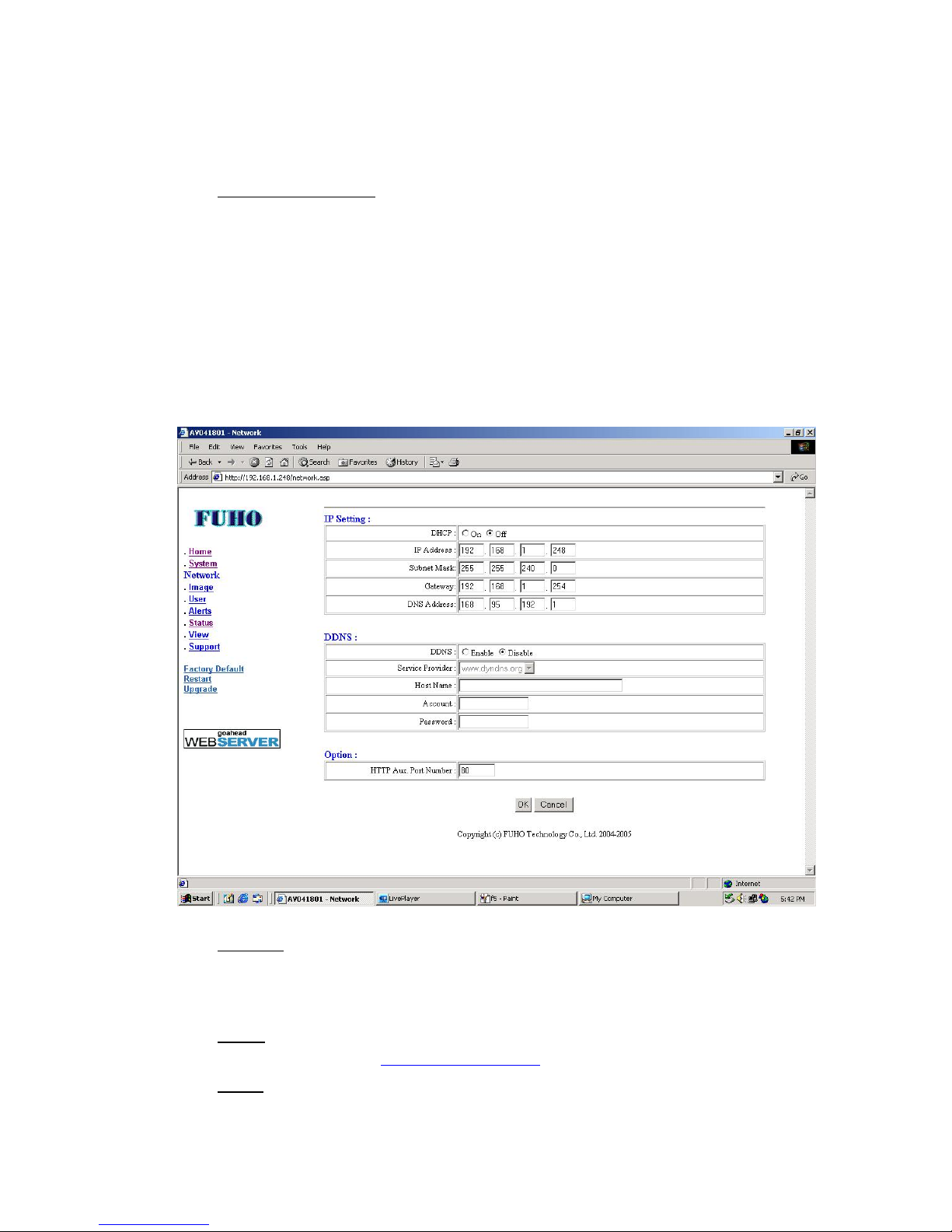
3.2.5 Network
DHCP, DDNS and HTTP can be modified in “Network”. Click OK upon information
amended.
IP Setting
DHCP on IP-CAM detects and receives IP address from NAT network. IP
address 192.168.1.200 will be used in condition of NAT router not detected.
DHCP off IP-CAM works in static IP mode.
DDNS
Please register on http://www.dyndns.com prior to DDNS setting.
Option
HTTP control port Number: 80
Page 35
IP901 User’s Manual
Page 35
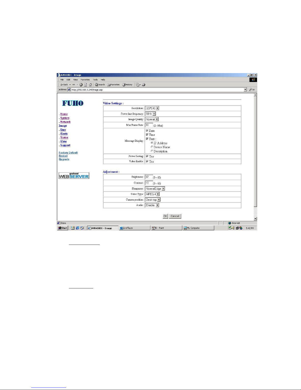
3.2.6 Image
Provides image format settings including resolution, compression quality and live mode
display. Picture quality adjustment includes brightness, contrast, sharpness and audio.
Image rotation provides mirror and reversal function. Please click ok upon setting finished.
Video Settings
Provides image format settings including resolution, compression quality and live
mode display. There are three options on resolution: 640*240、320*240、160*128.
Power line frequency:50HZ/60HZ can be different from different area. Image
Quality: High/Normal/Low. Image quality will decline in condition of Max Frame
Rate. Default frame rate 30 is the second best.
Adjustment
Provides adjustment on brightness, contrast and sharpness.
3.2.7 User
Provides administrator information and password setting. Provides User Name and
Password setup also. Only users in the list are authorized to enter system setup.
Administrator is the only user to get into user setup. Please click ok upon setup finished.
Page 36
IP901 User’s Manual
Page 36
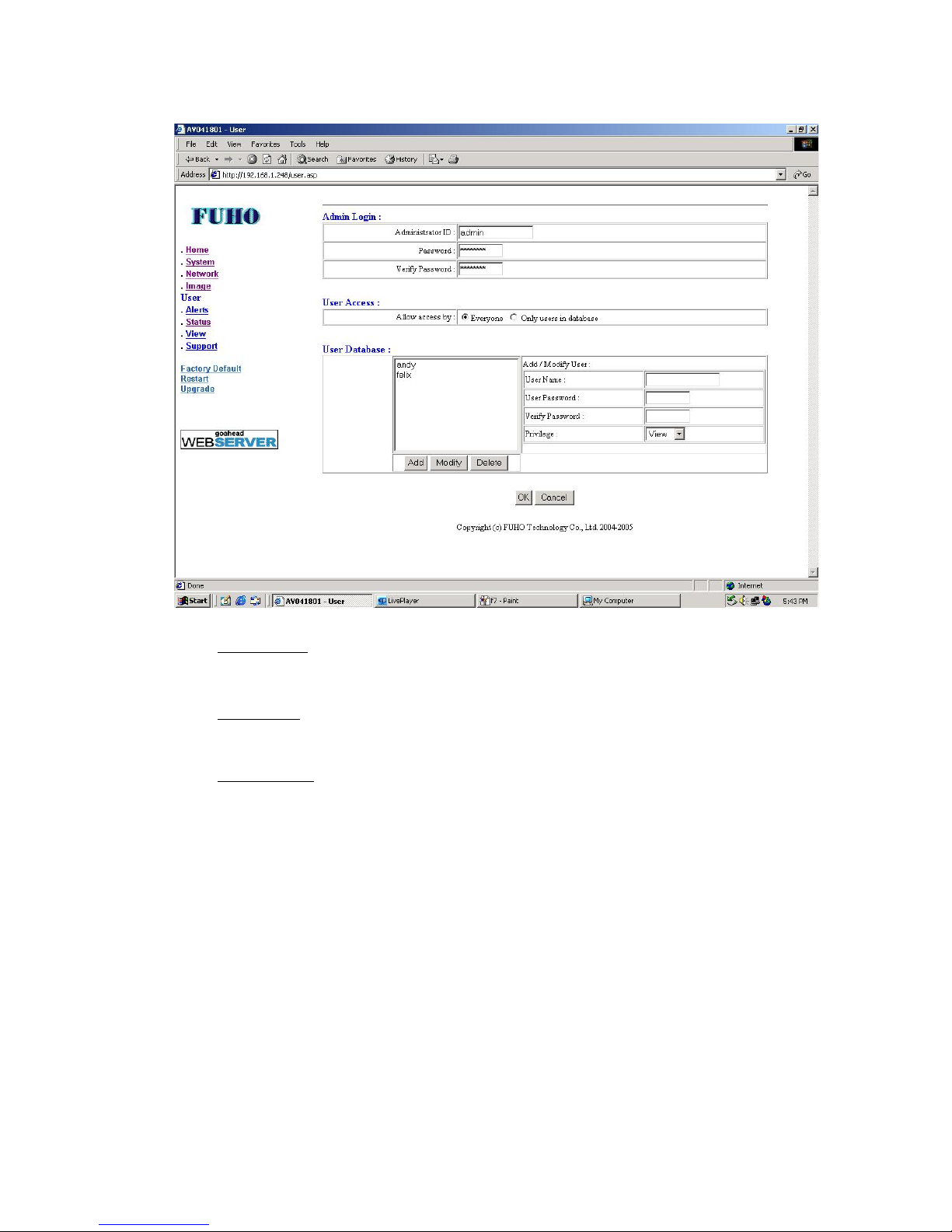
Admin Login
User Name and Password can be created and amended in Admin Login. User
Name and Password must be kept in mind firmly.
User Access
Click “Everyone” for all users viewing via network. Click “Only users in
database” for users in the list only viewing via network.
User Database
Administrator creates users in the list and gives authorization to the users. Input
User Name and Password. Setup authorization in “Privilege” down pull bar.
Click “Add” to save the information upon setup finished.
3.2.8 Alert
IP-CAM comes with external sensor input and motion detection. Setup parameters can
be modified. Record mode, email transmission and ftp upload can be pre-scheduled also.
Please click ok upon setup finished.
Page 37
IP901 User’s Manual
Page 37
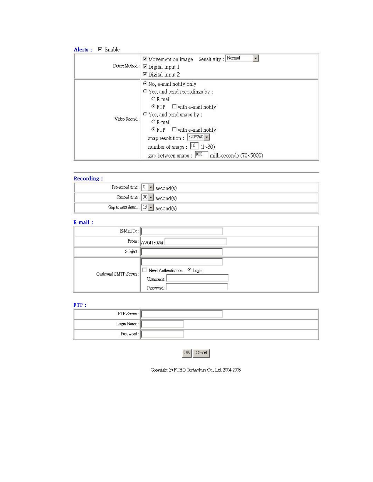
Alerts
Tick “Enable" to enable motion detection.
User can enable or disable Movement on image, Digital Input 1 and Digital Input 2 in
Detect Method. There are five degrees for the sensitivity of Movement on image.
Record mode, email transmission and ftp upload can be pre-scheduled in “Video
Record”. System sends emails only if “No, e-mail notify only”. System sends
Page 38
IP901 User’s Manual
Page 38
recorded files if “Yes, and send recordings only”. System sends snap pictures if
“Yes, and send snaps only”. Transmission can be email or ftp upload.
Recording
Pre-record time, record time and Gap to next detect can be modified.
E-mail
Create information about email transmission.
FTP
Information must be correct for ftp upload.
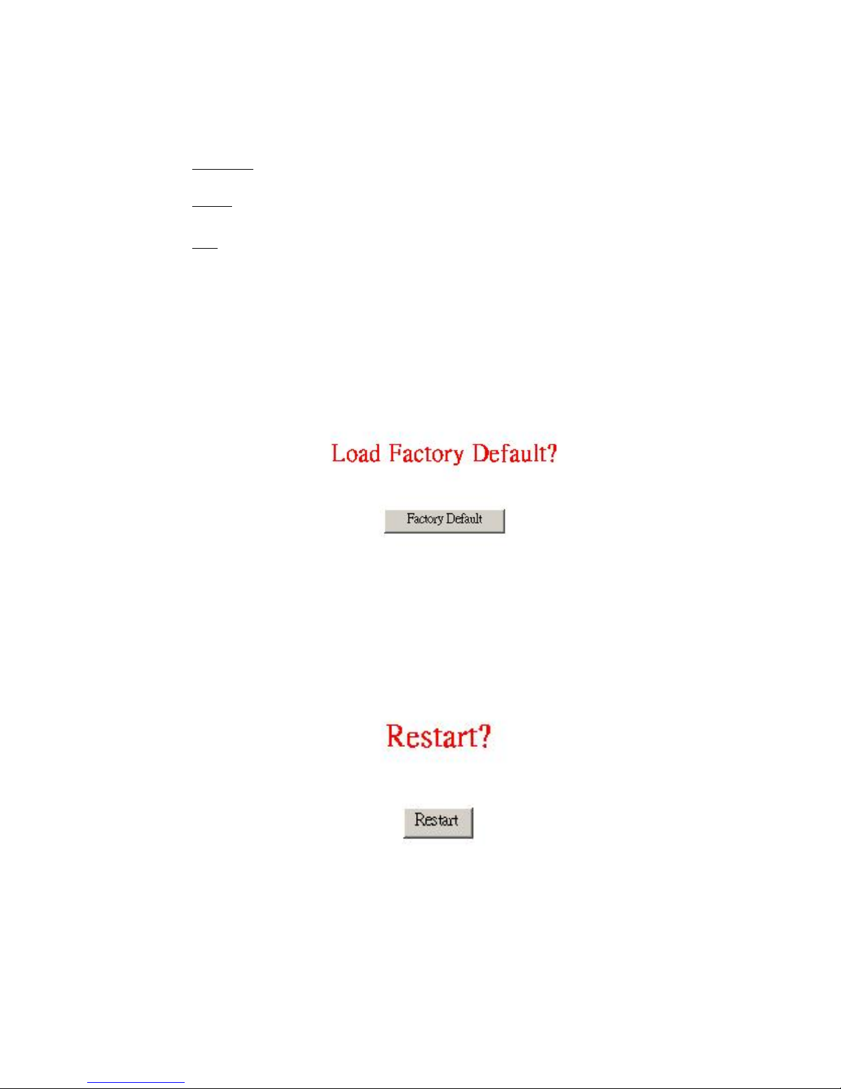
3.2.9 Factory Default Function
Back to factory default. Everything will be back to the initial including User Name,
Password and IP address.
3.2.10 Restart Function
Better restart system after amendment. Live mode must be closed prior to restart
function. It takes time to finish restart function. System gets back to “Status” when restart
finished. IP address should be given again if previous IP address changed while restarting.
Page 39
IP901 User’s Manual
Page 39
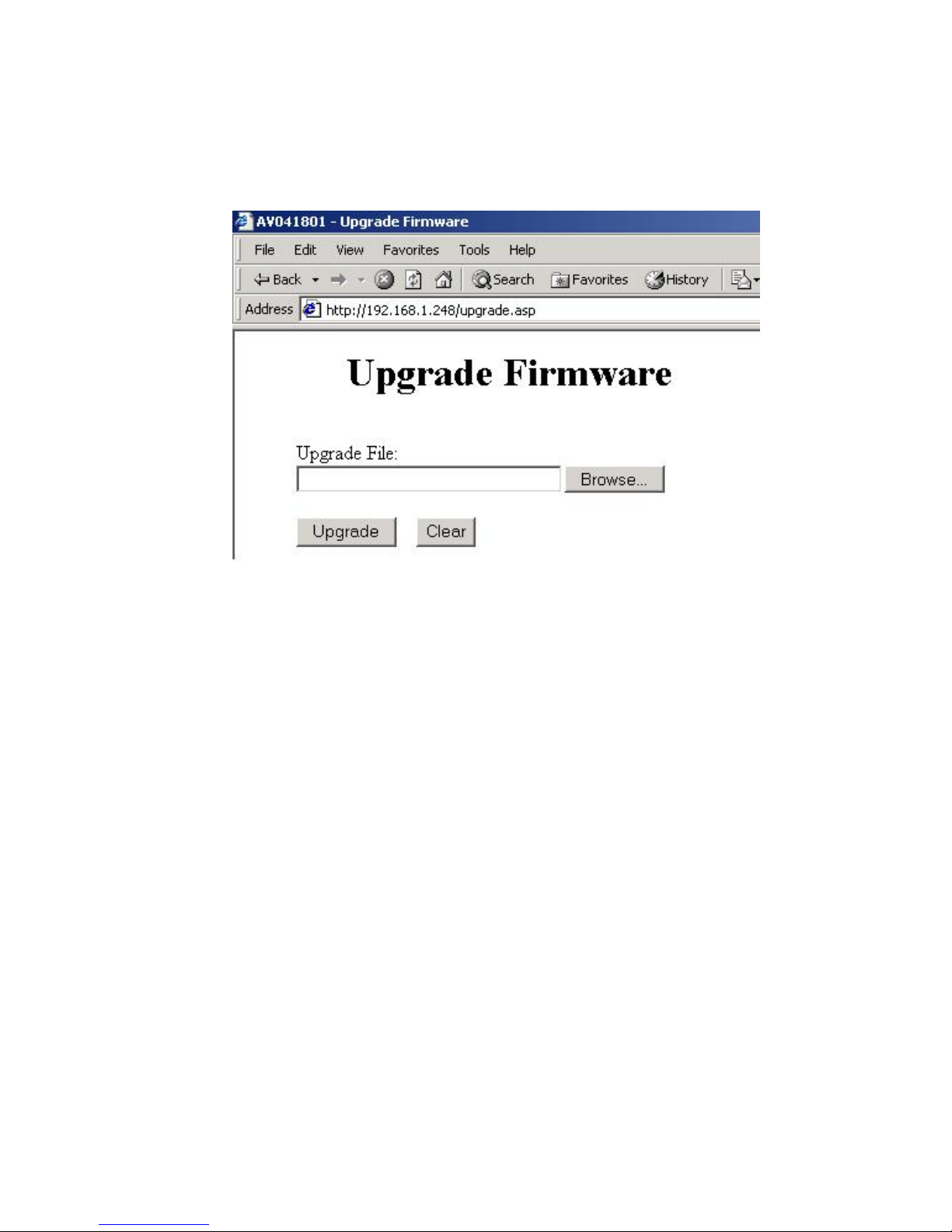
3.2.11 Upgrade
Firmware can be upgraded via IE browser.
Page 40

IP901 User’s Manual
Page 40
4. ELSE
4.1 SPECIFICATIONS
Compression
MPEG4 / JPEG
VGA 640x240
QVGA 320x240
Resolution
QQVGA 160x128
VGA (MPEG-4) 8 frames/sec
QVGA (JPEG ) 10 frames/sec
Transmission Speed
QVGA (MPEG-4) 26 frames/sec
Network Protocol TCP/UDP/IP, DHCP,SMTP, HTTP, NTP/SNTP,DDNS, and TFTP
File Format AVI (MPEG-4/M-JPEG video stream with 32kbps ADPCM audio)
Recorded format AVI (MPEG-4/M-JPEG video stream with 32kbps ADPCM audio)
Movement on image
Motion Detection
Digital Sensor
email
Email and file attached
Alert Files
Transmission
ftp upload
IE Browser Internet Explorer 5.0 or above
IP setup
Image Mirror
Image Reversal
Brightness
Contrast
Sharpness
Pan/Tilt Control --- FUHO MMS / PELCO-D
Camera Setup via IE
Audio on/off
Page 41

IP901 User’s Manual
Page 41
Memory 2M Byte Flash ROM / 8M Byte SDRAM
network 10/100 Ethernet
X1 power input port
X1 RJ-45 network port
X1 audio port
Motion Detection Port
X1 Video Input Port
X1 Video Output Port
X1 System Reset
I/O Ports
X1 RS-485 Control Port
Dimension 100mm × 170mm × 30mm
Weight 800g
Power Input DC +12V
Power Consumption 500mA
Operating
Temperature
5°C ~ 40°C
Storage Temperature 0°C ~ 70°C
Humidity 10% ~ 80%
 Loading...