

Page 1

FuG Elektronik GmbH, Am Eschengrund 11 D-83135 Schechen
Tel.: +49(0)8039/40077-0 Fax: +49(0)8039/40077-99 info@fug-elektronik.de www.fug-elektronik.de
Medium Voltage Power Supplies
MCP - Series
up to power class 15kW
certified according
ISO 9001 : 2008
Operating Instructions
This instruction is only dedicated to electrical experts and people with a
suitable technical education, which are familiar with electrical risks and
can keep the risk for themselves and other people as low as possible.
For the operation of this unit only a.m. persons are admitted.
Page 2

MCP -Series FuG Elektronik GmbH, Am Eschengrund 11, D – 83135 Schechen
File: MCP Rev 6_englisch.docx Rev 6 2 von 16
Content:
1. Safety Instructions ............................................................................................................... 3
2. General ................................................................................................................................ 4
2.1 Setup Information ................................................................................................................ 5
2.2 Preparation for commissioning ............................................................................................ 5
3. Description ........................................................................................................................... 6
3.1 Front Panel, Controls ........................................................................................................... 6
3.2 Rear side, Connections........................................................................................................ 7
3.3 Assembly ............................................................................................................................. 9
3.4 Mode of operation ................................................................................................................ 9
4. Operation with local controls .............................................................................................. 10
5. Maintenance ...................................................................................................................... 10
6. Options .............................................................................................................................. 11
6.1 Analog Programming ......................................................................................................... 11
6.2 Digital Interface PROBUS V (Option)................................................................................. 14
7. Technical Data ................................................................................................ ................... 15
8. Calibration (Option) ............................................................................................................ 16
9. Certificate of Conformity .................................................................................................... 16
10. Accessories ....................................................................................................................... 16
11. Warranty, Repairs .............................................................................................................. 16
12. Special Models, Modifications ............................................................................................ 16
Page 3

MCP -Series FuG Elektronik GmbH, Am Eschengrund 11, D – 83135 Schechen
File: MCP Rev 6_englisch.docx Rev 6 3 von 16
Adhere strictly to the operating instructions before you either change
switches, or connect sockets, marked with this symbol!
Symbol for high Voltage outputs
Symbol for cassis earth, potential safety earth
1. Safety Instructions
The units of the series MCP deliver dangerously High Voltages! Ensure that
nothing and nobody will be endangered by this High Voltage before putting the
unit into operation!
Attention ! The full dielectric strength of the high voltage connectors is only achieved if
fully mated together.
Preparing for commissioning Make sure that you have read and understood the operating instruction manual!
Ensure that you observe all the hints and warnings contained within it. In not following
the operating instructions, you contravene the safety regulations for operating units of
this type. FuG accepts no liability for consequences arising from the failure to follow
these safety instructions.
Mains voltage Check whether the input voltage for your power supply, noted on the type label,
corresponds to your actual mains voltage.
Earth The unit is provided with a safety earth (German safety class I). For protection against
electric shocks, the unit must be connected to the mains via a suitable 3 or 5-pole
cable with a non-fused earth conductor. For electrical potential equalization to the load
and to the center of the AC-supply, the earth stud must be used.
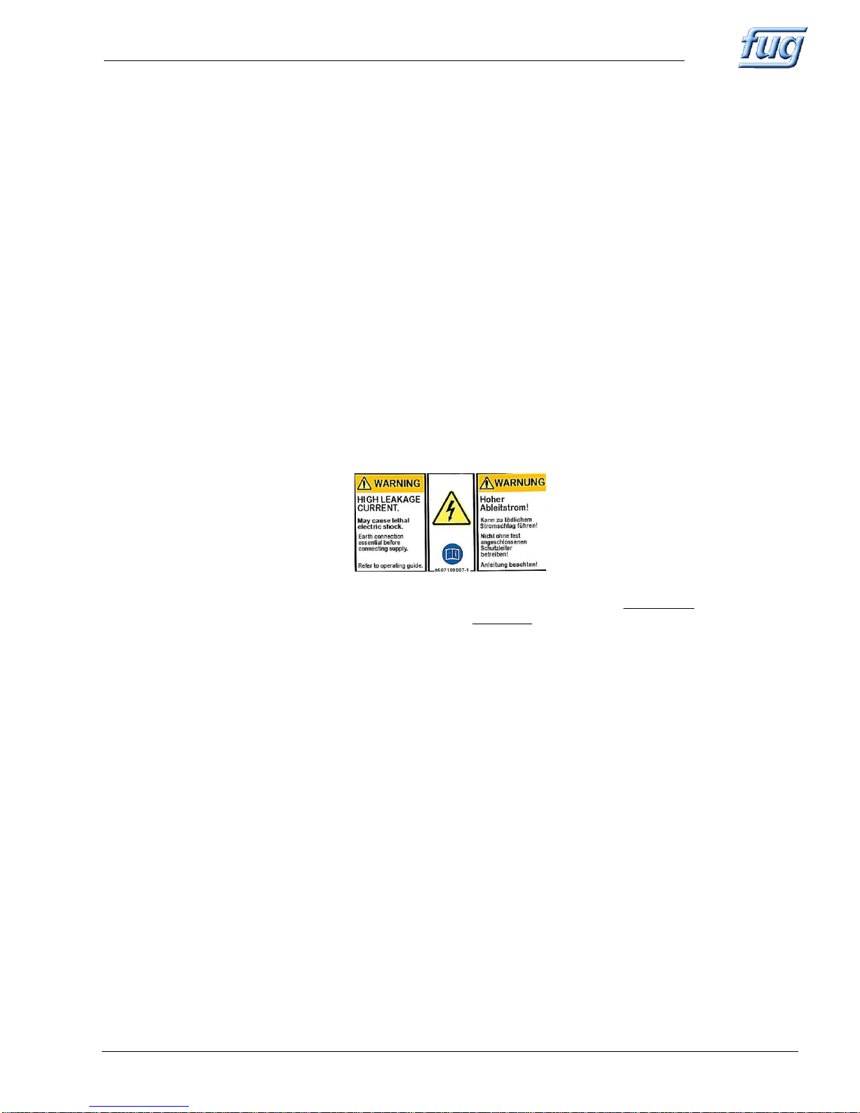
High leakage current! Labeled by a sticker on the rear. At a high leakage current is an earth connection to
the Earth stud mandatory.
Operating environment The units may only be operated in a clean, dry environment.
Please make sure that no objects or liquids can enter the casing through the
ventilating apertures.
Because of the risk of sparks, the unit must not be operated in the vicinity of
flammable gases or fumes.
Cooling To ensure an adequate cooling, the ambient temperature must not exceed 40°C.
This unit is air cooled by convection or at units >700W by forced ventilation.
Therefore please ensure that an adequate air-flow is available and that nothing is
placed either above or below the unit which may impede this air-flow.
Do not operate table top units without the mounted legs and do not expose the unit
directly to solar radiation.
If the unit is used as a plug-in component, sufficient air-flow must be provided,
(1HU = 44,5 mm above and below clear).
Opening the unit Before opening, ensure that the unit is disconnected from the mains!
The unit may be opened by operating personnel only for the purpose of operating
switches as described in the operating instructions, (e.g. baud rate switch of Probus V,
which is inside).
Danger: The electronic boards inside the power supply are connected to one output pole
and can therefore lie on up to 2000V during operation.
ATTENTION! The unit contains capacitors, which discharge only very slowly (typical
discharge time 5 min) or, in worst case, do not discharge at all.
For switch over use isolated tools only.
Maintenance or repair of this unit should only be carried out by trained service
personnel who are aware of the inherent dangers of such equipment.
Symbols
Page 4

MCP -Series FuG Elektronik GmbH, Am Eschengrund 11, D – 83135 Schechen
File: MCP Rev 6_englisch.docx Rev 6 4 von 16
2. General
The units of the series MCP (Medium Voltage Chopper Power Supplies) are high
stable DC- power supplies with low ripple.
High Voltage Output ATTENTION! The units supply dangerously HIGH VOLTAGE!
Polarity Both output terminals are floating (not with option analog programming), either the
negative or the positive pole can be connected to earth.
Output Isolation At units up to 350 V nominal voltage each output terminal may float up to ±500 V with
respect to earth, from 650 V to 2000 V nominal voltage up to ±2000 V.
At units with analog programming (not floating) from 650 V on one pole is internally
connected to earth.
Short-circuit Protection All units are short-circuit proof. The maximum current can be supplied for all output
voltages, even in case of a short-circuit.
ATTENTION! During short-circuit or flash over, the internal filter-capacitors will be
discharged very fast. The output current is only limited by internal safety
resistors and can reach a value 500 times higher than the nominal value.
Load Types The type of load is optional. All passive bipolar loads can be connected.
Series Connection A series connection is possible, paying attention to the stated output isolation. That
means at a series connection of power supplies the sum voltage of both power
supplies may not exceed the mentioned value.
Parallel Connection Parallel connection of power supplies with similar nominal voltage is supported.
Type Number From the type number you can see both the power class and the maximum output
voltage of the unit.
Example: MCP 14 - 2 000 = Power class 14W / Nominal voltage 2 000V
Modifications Modified types with differing electrical or mechanical data are indicated by a "M" within
the type number, or are marked with a label “modifiziert” or "modified"
(e.g. MCP 35M - 2000).
(In this case pay attention to the description in section 8)
Serial Number The label on the rear of the unit, the technical manual and the circuit diagrams show
the serial number.
It has the following content:
Serial No.:
AAAAA-PP-NN YYYY/MM
Internal order number
Item number
Consecutive number out of this item
Deliv ery Year / Month
IMPORTANT Please indicate on all further enquiries for warranty, service or spare parts
orders the serial number and the model number of the unit.
Page 5
MCP -Series FuG Elektronik GmbH, Am Eschengrund 11, D – 83135 Schechen
File: MCP Rev 6_englisch.docx Rev 6 5 von 16
2.1 Setup Information
Operating position The units may only be operated in horizontal position.
Class of pollution The units are designed for the pollution class 1 (normal, not conductive pollution).
EMC The units are built according to current standards. When length of signal- and control
lines up to 3m length.
Transport If the power supply is equipped with lifting appliances or handles, the weight of the unit
must be shared to these points.
2.2 Preparation for commissioning
Mains Voltage Check whether the input voltage for your power supply, noted on the type label,
corresponds to your actual mains voltage.
Use only the enclosed delivered mains cable.
Earth, Safety Conductor The unit is provided with a safety earth (German safety class I). For protection against
electric shocks, the unit must be connected to the mains via a suitable 3 or 5-pole
cable with a non-fused earth conductor.
For electrical potential equalization to the load and to the center of the AC-supply, the
earth stud must be used.
High leakage current! When this sticker is placed on the rear side of the unit or the text “High leakage
current” is engraved , the unit must be grounded properly by using the appropriate
grounding bolt with a cable of at least 10 mm ² cross section.
Fuses Internal: See type label.
External: On mains side next higher size, characteristics delay-action or if automatic
cut-out is used, characteristics "C" or "K".
Load connection The output is floating. Pay attention to the in section "2. General" stated voltage limits
for the output isolation.
The load always has to be connected between the positive and the negative output
terminal of the power supply. The return current must not flow back via mains earth!
The screen of the HV- cable always must be connected at earth potential.
Max. isolation voltage: up to 350V nominal voltage -> ± 500V
from 650V nominal voltage -> ± 2000V
At units up to 350 V output voltage use only safety connectors according
IEC 1010-1 or VDE 0110.
At units from 650 V on use the enclosed connector only.
Attention! Please obtain the limitation of isolation at units with option “analog
programming”.
See section 6.1 “analog programming”
Page 6

MCP -Series FuG Elektronik GmbH, Am Eschengrund 11, D – 83135 Schechen
File: MCP Rev 6_englisch.docx Rev 6 6 von 16
3. Description
3.1 Front Panel, Controls
Figure: Front panel of a MCP 14 – 2000 unit. The dimensions of devices with higher power are different to this type.
1
Mains Power Switch. Provides two pole isolation
from mains network
12
voltage display:
flashing: set value is displayed
non flashing: actual value is displayed
2
Output release. No mains disconnection.
13
current display:
flashing: set value is displayed
non flashing: actual value is displayed
3
Output release status.
Indicates controller and output active.
14
indicates control state Constant Voltage CV
4
(Option) Selects control between LOCAL and
REMOTE
15
indicates control state Constant Current CC
5
(Option) Selects control between
REMOTE/ANALOGUE and REMOTE/DIGITAL
16
switches display to set value
6,7,8
(Option) Indicates the active control input
17
Potentiometer for voltage set value limitation (adjustable
only with a tool)
9
(Option) indicates Data traffic on digital interface
18
indicates active voltage set value limitation
10
lockable Potentiometer for voltage set value
19
indicates overtemperature
(ambient temperature too high, fan failed or dusty)
11
lockable Potentiometer for current set value
20
DC POWER SUPPLY
MCP 14-2000
0...2000V 0...6mA
OFF
ON
OUTPUTPOWER
V-LIMIT
CV CC
CURRENTVOLTAGE
SET VALUES
TEMP
V mA
1
3
2
4
7
8
5
9
19
14
10 12 18 17 16 13 15 11
DIGITAL
ANALOG
PROGRAMMING
REMOTE
LOCAL
BUSY
6
Page 7

MCP -Series FuG Elektronik GmbH, Am Eschengrund 11, D – 83135 Schechen
File: MCP Rev 6_englisch.docx Rev 6 7 von 16
3.2 Rear side, Connections
Figure: Rear side of a MCP 14 – 2000 unit. The dimensions of units with higher power and/or other voltages are
different to this type. In this case the arrangement of the elements can be different as shown above.
1.
Mains power input, built in fuses
up to 700W: Mains plug as shown above.
1400W and higher: Tightly with automatic cutout and lable connection or mainsplug C20 (IEC60320).
2.
earth stud. (only with high leakage current)
3.
mounting place for optional analogue programming
4.
mounting place for optional interface Probus V (i.e. IEEE-488, RS232, USB, LAN)
5.
high voltage output socket +
6.
high voltage output socket -
7.
earth stud.
i
0507100001-1
4
2
1
3
6
7
5
Page 8

MCP -Series FuG Elektronik GmbH, Am Eschengrund 11, D – 83135 Schechen
File: MCP Rev 6_englisch.docx Rev 6 8 von 16
Figure: Rear side of a MCP 5000 – 2000 unit. The dimensions of units with higher power and/or other voltages are
different to this type. In this case the arrangement of the elements can be different as shown above.
.
1
Mains Input with fix installed 3 or 5 phase cable.
2
Earth stud. Due to high leakage current PEN connection required!
3
Built in fuses for internal control fuse.
4
Automatic circuit breaker
5
Place for optional Interface (e.g..: IEEE-488, RS232, USB, LAN, ...)
6
15pol Sub-D connection e.g. Analog Programming (Optional)
7
Air outlet
8
HV-Output +
9
HV-Output -
10
Earth stud
5
2
7
4
136
10 89
i
0507100007-1
i
0507100001-2
Page 9

MCP -Series FuG Elektronik GmbH, Am Eschengrund 11, D – 83135 Schechen
File: MCP Rev 6_englisch.docx Rev 6 9 von 16
3.3 Assembly
The power supply consists of 4 main units:
Mains source and oscillating Unit
HV-transformer, HV-rectifier with filter, HV-divider and current measuring shunt
Control unit with measuring and control amplifier, reference voltage source, pulse
width modulator, source for the control unit from the mains transformer and a ±15
V voltage stabilizer.
Front panel board with 7-segment display, microcontroller, digital calibration
3.4 Mode of operation
The rectified mains voltage feeds the rectangular push-pull oscillator stage. For the
regulation, the rectangular voltage is pulse width modulated.
High voltage This rectangular voltage is transformed by a HV-transformer and dependent on type or
nominal voltage rectified by a bridge or a multiplier circuit.
Filtering The High Voltage so generated is filtered by a R-C-filter and fed to the output via a
protection resistor.
Voltage measurement A precision HV-divider feeds the measured voltage to the control circuit. For a better
performance, a voltage derived from a capacitive divider on the end of the rectifier is
added.
The divided voltage is normalized by an integrated amplifier to +10V = Vnominal.
Voltage control The normalized voltage forms the actual value for the control amplifier. The measuring
socket and the V-monitor are also supplied from this voltage. The voltage control
amplifier compares this voltage with the setting voltage (reference voltage divided by
the setting potentiometer or an external programming voltage).
The difference is amplified and fed, as control signal, to the input of the PWM- circuit,
which drives the oscillator unit.
Voltage limitation The voltage set value can be limited by a potentiometer on the front panel. The
limitation is always active, independent of the operation mode of the power supply.
Current measurement The current in the earthy pole of the HV-rectifier flows through a current measuring
resistor. The voltage drop on this resistor is also normalized by an integrated amplifier,
(+10V = nominal current).
Current control This normalized voltage serves as actual value for current control and is also
connected to the current monitor. The control amplifier for output current control
compares this voltage to the set value.
Internal supervision The ±15 V source of the control electronics is monitored.
Operation of the control unit is only released if the supply voltages are within their
limits.
Overtemperature The temperature of the internal power circuits in fan cooled units is monitored. In case
of overtemperature, the power circuits are electronically switched off and LED OT
(overtemp) goes on.
Reset after cooling down by switching the unit off and on again.
Possible reasons for overtemperature: fan blocked or dusty, ventilation slits blocked.
Page 10

MCP -Series FuG Elektronik GmbH, Am Eschengrund 11, D – 83135 Schechen
File: MCP Rev 6_englisch.docx Rev 6 10 von 16
4. Operation with local controls
The unit delivers dangerously High Voltage!
Please follow the safety instructions in section 1
Please notice in particular Load connection in section 2.2
Select local operation If your power supply is equipped with one of the options “analog or digital
programming”, set switch (4) to LOCAL.
Save switch on First, set switch OUTPUT (2) to OFF.
Now you can switch on the POWER switch (1). The output will remain OFF.
The LED LOCAL (6) is on, indicating local operation.
Set value Display Shortly pressing SETVALUES (16) switches both displays to display the valid set
values.
With potentiometers Voltage (10) and Current (11) the needed set values can be
adjusted.
The displays begin to flash, indicating the set value display mode and switch back
after some seconds to actual value display.
Pressing the SETVALUES key longer than appr. 2 seconds, the displays stay in set
value display mode until the key is pressed again.
Adjustment Range The internal potentiometers provide an adjustment range of appr. 0,1% to 100% of
their nominal value.
Adjustment of voltage limit Turn the voltage potentiometer clockwise to its limit and switch to set value display.
With a screwdriver you can now adjust the maximum voltage on the potentiometer
(17). During this, the LED V-LIMIT is on and the limitation voltage is displayed on the
left display.
If you wish no voltage limitation, simply turn the potentiometer (17) clockwise to its
limit. LED V-LIMIT goes off.
Turn voltage potentiometer back to the desired set value and switch display mode to
actual value display (press key SETVALUES (16))
The voltage limitation is always active. It limits the maximum output voltage
also in operating mode “analog programming” or “digital programming”.
Output release After adjustment of the set values, the output voltage can be released with switch
OUTPUT (2).
The LED ON (3) indicates the released output.
Control mode indication Depending on the adjusted set values and connected load, the power supply will run
either in constant voltage CV (14) or constant current mode CC (15).
Save switch off The following switch off procedure is recommended:
First, inhibit the output with key OUTPUT (2). LED ON (3) goes off.
After the output voltage has reached a low and save value, you can switch off the
power supply with POWER (1).
This procedure gives you more safety, because the slow ramping down of the output
voltage can be monitored on the display.
At immediate switch off with POWER switch, there could be charged capacitors
remaining on dangerously high voltage that cannot be recognized, because display
turns dark immediately.
5. Maintenance
At units with fan the fan grids must be cleaned from time to time, depending on the
pollution.
Besides that the MCP series needs no maintenance.
Page 11

MCP -Series FuG Elektronik GmbH, Am Eschengrund 11, D – 83135 Schechen
File: MCP Rev 6_englisch.docx Rev 6 11 von 16
6. Options
6.1 Analog Programming
Features Controlling of voltage, current and output on/off by the analog interface.
Provides the readout of actual values as analog voltages and latest control modes as
digital status signals.
Select analog programming Set switch (4) to REMOTE.
If the power supply is additionally equipped with option Probus V (digital
programming), set also switch (5) to ANALOG.
LED ANALOG (7) indicates analog programming selected.
Now the power supply is controlled by the signals on connector (3).
Voltage and current are controlled by standard control voltages of 0..10V.
0...10V control voltage can be derived from an external potentiometer or some other
source, i.e. PLC.
Through special connections internal and external control can be combined. See
examples below.
Voltage limitation The voltage set value limitation is always active. Adjustable with Potentiometer V-
LIMIT (17) on the front panel.
Cable shielding Connection cables to the analog programming connectors must be shielded.
The cable shield must be connected to earth, i.e. to the mounting nuts of the
connector.
ATTENTION! The reference pins "0V" (pin 6 and 9) for all external programming voltages are
connected to the output terminal "A-".
That can cause voltages on the programming terminal up to 500V! Please make sure
that the connection cable for the programming and the following equipment has a
dielectric strength of min. 500V against earth (screen).
(A programming connector with 500 V rating is enclosed).
Precision, Linearity,
Stability and
Temperature Drift Due to the direct coupling of analog signals, there is no degradation of the power
supply performance.
6.1.1 Floating Analog Programming (2kV)
Mode of Operation The analog signals for voltage and current set values as well as the monitor signals for
voltage and current are galvanically isolated by means of optical fibre.
Digital signals are also isolated with optical fibre.
Identification You can see, if your power supply is equipped with directly connected or floating
analog programming on a label or engraving "FLOATING ANALOGUE
PROGRAMMING“ on the backpanel.
Pin Assignment Same as Directly Connected Analog Programming, but Pins 4 and 5 are not
connected. Use of internal potentiometers not possible.
Isolation There is no galvanic connection between the power supply output potential and the
programming potential. The isolation is rated for 2kVDC.
The 0V potential of the power supply can be operated fully floating up to +/- 300V.
Maximum potential on the programming connector is ±30V DC with respect to earth.
Accuracy, Linearity <±5x10⁻⁴ based on nominal value (10V)
and Stability
Temperature Drift <±1,5x10⁻⁴/K of nominal value (10V); typical 5x10⁻⁵/K
Examples for wiring an analog interface:
Note: An external voltage adjustment implicitly requires the wiring of the current control and
vice versa!
The reference voltage (+10V) or the set value voltages can be supplied by some other
Page 12

MCP -Series FuG Elektronik GmbH, Am Eschengrund 11, D – 83135 Schechen
File: MCP Rev 6_englisch.docx Rev 6 12 von 16
sources, i.e. PLC or PC plug-in cards (0V must be connected)
The UNIT-ON command (Pins 12-6) must be connected implicitly.
ATTENTION! If the unit is switched off or mains fails possibly existing output voltages or
currents will not be displayed on the monitor terminals.
Page 13
MCP -Series FuG Elektronik GmbH, Am Eschengrund 11, D – 83135 Schechen
File: MCP Rev 6_englisch.docx Rev 6 13 von 16
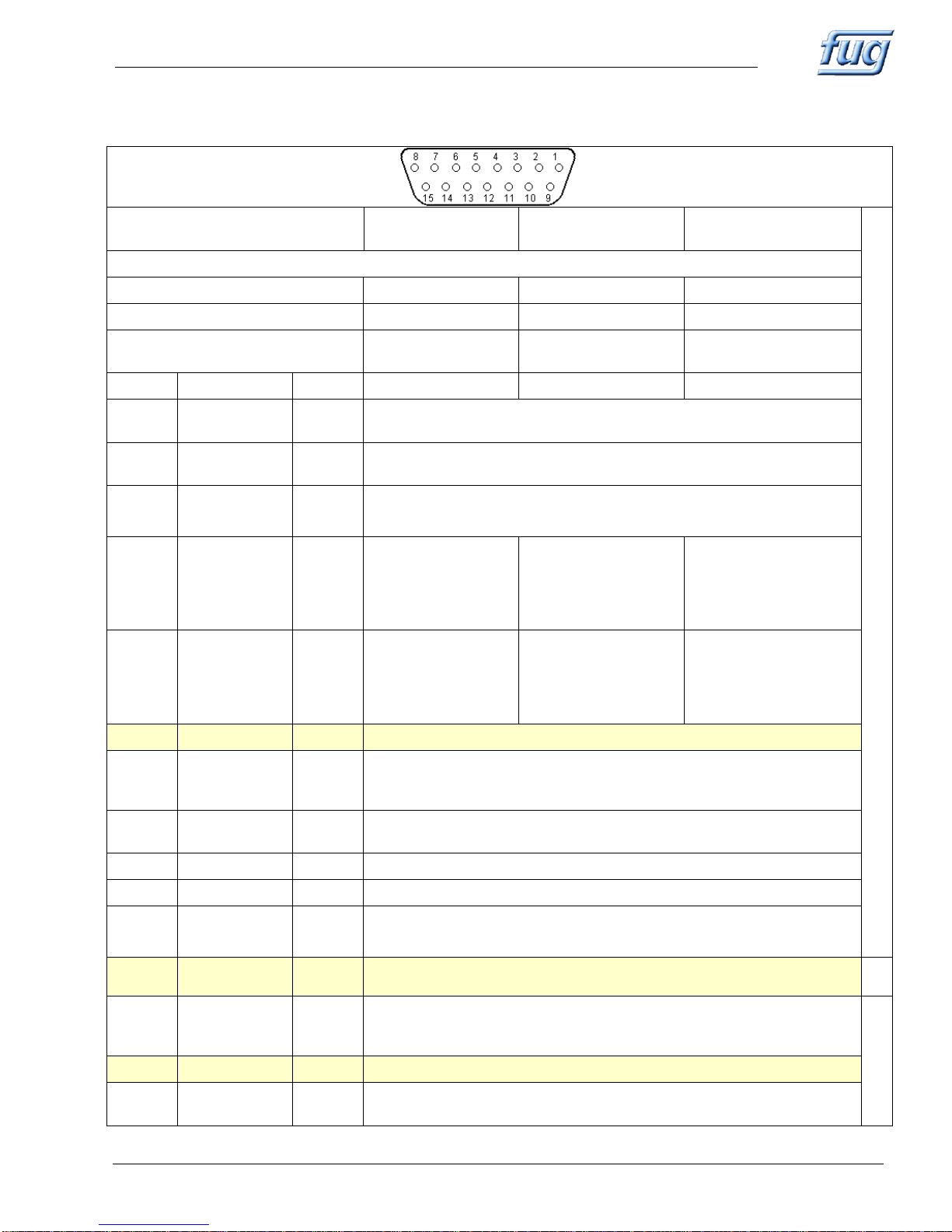
Versions of analog Programming
Plug connection
View of solder side Plug
All voltages and currents are
specified in DC
Standard
Non-isolated
600V potential free
2kV potential free
ANALOGE PROGRAMMIERUNG STANDARD
Isolation maximal 30V against ground (see catalog „Options and Modification)“
Isolation of the digital Inputs
0V
600 V
2000V
Isolation of the digital Outputs
0V
600 V
2000V
Isolation of the analog
In and Outputs
0V
600 V
2000V
Pin No.
Description
Type
Function
Function
Function
1
CC
DA
Supplies appr. +15V if power supply is in constant current mode.
Equivalent to LED CC on front panel.
2
CV
DA
Supplies appr. +15V if power supply is in constant voltage mode.
Equivalent to LED CV on front panel.
3
I-MON
AA
Actual output current monitor signal 0..+10V represents 0..nominal current
Ri ca. 10kΩ
Ri ca. 2kΩ
Ri ca. 11kΩ
4
VPS
AA
Slider Voltage Pot on
front panel
0..+10V for 0..nom.
Voltage
Ri ca. 10kΩ
Not used
Not used
5
IPS
AA
Slider Current Pot on
front panel
0..+10V for 0..nom.
Voltage
Ri ca. 10kΩ
Not used
Not used
6
0VD
DE
Ground for digital signals, may be current loaded
7
POL-SET
(option)
DE
Control input for motor driven polarity reversal switch.
pin 7 open: positive polarity
pin7 connected to 0VD (pin 6) : negative polarity
8
V-SET
AE
0...+10V controls 0...nominal voltage
Input resistance to 0V appr. 10MOhm
9
0V
A-GND
Ground for analog signals, must not carry any current
10
+10VREF
AA
+10V Reference
11
V-MON
AA
Actual output voltage monitor signal.0...+10V represents 0...nom. voltage
Ri ca. 10kΩ
Ri ca. 2kΩ
Ri ca. 11kΩ
12
UNIT ON
DE
A connection to Pin 6 (OVD) releases the output voltage
Same function as switch OUTPUT on front panel.
13
POL-Status
(option)
DA
Actual positions of the voltage reversal switch
appr. +12V : positive polarity
0V: negative polarity:
14
+NC
Not connected
15
I-SET
AE
0..+10V controls 0..nominal current
Input Resistance to 0V appr. 10MOhm
Page 14

MCP -Series FuG Elektronik GmbH, Am Eschengrund 11, D – 83135 Schechen
File: MCP Rev 6_englisch.docx Rev 6 14 von 16
6.2 Digital Interface PROBUS V (Option)
The flexible Interface System Probus V consists of two parts, that communicate over a
fiber optic connection.
Unit ADDAT30 (short “ADDA”) is an AD/DA interface that controls the power
supply. ADDA is connected to an interface converter via fiber optics. ADDA is
located as a plug on module on the power supply electronics. It is accessible
after opening the left side panel of the housing.
The interface converter that connects ADDA to different bus-systems, is
located at the back panel of the power supply.
It can also be operated outside the power supply. In that case, the outside
connection is fiber optic and therefore, a maximum of EMC ruggedness can
be achieved.
At the moment, interface converters are available for the following bus-systems:
USB
IEEE-488
LAN (Ethernet)
RS232
RS422
RS485
Profibus
CANopen
Analog 0..10V
Features (short form) “Probus V” provides commands to set output voltage, output current and to switch the
output voltage.
Set values can be ramped with defined speed.
High resolution read back of actual values.
Programming speed Up to 2000 set values per second possible. (depending on the interface converter)
Select Digital Interface Set switch (4) to REMOTE.
If the power supply is additionally equipped with an “analog programming” option, set
also switch (5) to DIGITAL.
LED DIGITAL (8) indicates digital programming selected
Status indication LED BUSY (9) flashes on data traffic.
Voltage limitaion The voltage set value limitation is always active. Adjustable with Potentiometer V-
LIMIT (17) on the front panel.
Further Information A detailed description of the Probus V system (command set, driver installation etc.) is
provided in separate manuals that come along with Probus V.
Page 15

MCP -Series FuG Elektronik GmbH, Am Eschengrund 11, D – 83135 Schechen
File: MCP Rev 6_englisch.docx Rev 6 15 von 16
7. Technical Data
All here stated data are valid for voltage and current control in internal operation.
For changes of the technical data with the options analog and digital programming see corresponding sections.
AC - Input 230V ±10% 47 - 63 Hz or 400V ±10%, 3-phase, 47 - 63 Hz, depending on
the type, see type label. Overvoltage category II according to IEC664.
N-connection and PE (non fused earth) always necessary!
For devices with high leakage current required PEN
At plug-type connections: performance according to
- IEC 60320-C14 until 700W
- IEC 60320-C19 700W until 1400W
- Cable connect (Three Phase Currant)
EMC Standards See Certificate of Conformity
Safety See Certificate of Conformity
Environment Conditions Operating room: Only for indoor usage (see section 2.1.)
Temperature: 0 °C to 40 °C
Air humidity: Max. relative humidity 80% until 31 ºC,
linear decreasing until 50% relative humidity at 40 ºC
Atm press: Altitude max. 2000 m over sea level
Contamination: 1
Protection Class IP20
Output Voltage / Current See front panel of the power supply.
Output Polarity floating, each output terminal may be connected to earth (for exceptions see options)
Output Isolation At units up to 350V nominal voltage each output terminal may get max. ±500 V with
respect to earth.
At units from 650V to 2000V voltage each output terminal may get max. ±2000 V
with respect to earth
Attention ! Not partly valid for units with "analog programming", see section 6.1
Setting Range Voltage With Potentiometer VOLTAGE appr. 0,1% to 100% from nominal value
Current With Potentiometer CURRENT appr. 0,1% to 100% from nominal value
Reproducibility ±1x10⁻³ from nominal value, with potentiometer on the Front panel
Setting Resolution With potentiometer on the front panel 1x10⁻⁴ from nominal value
Residual Ripple <5x10⁻⁵ pp +50mVpp from nominal value (units up to 350W nominal power)
<2x10⁻⁴ pp +200mVpp from nominal value (units from 700W nominal power on)
Deviation <±1x10⁻⁵ from nominal value, for ±10% mains voltage variation
<1x10⁻⁴ from nominal value, for 0 to 100% load variation
<±1x10⁻⁴ from nominal value, over 8 hours
<±1x10⁻⁴/K from nominal value at temperature variation
Regulating Time
voltage control <1ms for load variations from 10% to 100% or 100% to 10%
current control <10ms for load variations causing an output voltage variation less than 10% of the
nominal voltage.
Discharging Time Constant at unloaded output max. 10 sec
Discharging Time down to < 50V max. 1 min.
Programming speed <300ms for changes of output voltage from 10% to 90% resp. 90% to 10%
at nominal load
Voltage and Current Display DVM for voltage and current, extent ±20000 Digits
Status Display LEDs for constant voltage, constant current, set value limitation active, setting of
programming switch, Output ON, overtemperature
Mechanical size Depending on type, changes reserved.
Page 16

MCP -Series FuG Elektronik GmbH, Am Eschengrund 11, D – 83135 Schechen
File: MCP Rev 6_englisch.docx Rev 6 16 von 16
8. Calibration (Option)
Calibration Certificate All guaranteed data for our power supplies are tested in the factory and documented
in an internal test protocol.
On request we can offer optionally a calibration in our plant. In this case the customer
receives a calibration certificate due to our ISO 9001 : 2008 certified quality system.
We confirm the compliance of the output data with our catalog data. A blue calibration
sticker than refers to the next recommended calibration date.
Subsequent Calibration Generally we recommend an annual subsequent calibration.
9. Certificate of Conformity
The power supplies carry the CE-sign. Please read the Certificate of Conformity.
10. Accessories
Connectors, Cables See enclosed Mounting Instructions
Mounting instructions
Rack Adapter Attention! Before opening the power supply, disconnect from
mains!
The front panel handles must be exchanged separately. (Please don’t exchange
together, because the front panel would not be fixed).
Is the power supply only be used as plug-in unit, the stands may be removed.
For that remove the bottom sheet. The stands can be removed by using a screwdriver
for recessed-head screws. Then place back the bottom sheet.
Caution!! After removing the stands, the power supply may not longer be used as a table-top
unit, because no convection cooling is possible, risk for overheating.
11. Warranty, Repairs
Your power supply has been assembled and tested under stringent quality assurance
procedures.
We provide a 2 years warranty, commencing with the delivery date stated in the
serial number.
This warranty does not cover misuse or attempted repair by untrained personnel.
Enclosed you will find one set of circuit diagrams for service purposes.
In all further enquiries for service or spare parts, please provide both the model and
serial number of the unit
12. Special Models, Modifications
Power Supplies that are equipped with special modifications are identified with an "M"
within the type designator (i.e. MCP 35M - 2000) or the label "MODIFIED".
Please refer to the separate data sheet attached.
 Loading...