

Page 1
INSTALLATION
MANUAL
9 OCTOBER 2009
Syn-Tech Systems, Inc.
P.O. Box 5258
Tallahassee FL 32314
www.syntech-fuelmaster.com
Page 2

Page 3

TABLE OF CONTENTS
SECTION 1 - GENERAL INFORMATION ................................................................. 7
Proprietary Information ...................................................................................... 7
Introduction....................................................................................................... 7
Purpose ............................................................................................................ 7
Safety Precautions and Corrective Actions ......................................................... 8
Protecting Against Electrostatic Discharge .............................................................. 8
Correcting RF Interference ..................................................................................... 8
Certification/Approval ........................................................................................ 9
WARNINGS, CAUTIONS, and NOTES ................................................................ 9
FuelMaster® Warranty........................................................................................ 9
Initialization Requirement ..................................................................................10
Safety Related Inspections and Preventive Maintenance .....................................10
Consumables/Special Tools ...............................................................................10
Improvements ...................................................................................................11
SECTION 2 – SYSTEM DESCRIPTION ...................................................................13
FuelMaster® Passive Fueling..............................................................................13
Typical Fueling Transaction ..........................................................................13
Installation Requirements .............................................................................15
Components of a Passive Fueling System ..........................................................15
FMU-3500 and FMU Upgrades ......................................................................15
FMU-3535 Passive Mobile ............................................................................16
Automotive Information Module .....................................................................16
AIM2™ Module External Antenna ..................................................................17
Access Point ................................................................................................17
AIM2™ Programming Key .............................................................................17
Nozzle Tag ..................................................................................................17
3
Page 4

TABLE OF CONTENTS (con’t)
Programming Hose Tag (PHT) ......................................................................17
Filler Neck Rings/RFID Interface Module .......................................................19
Connecting Cables .......................................................................................19
SECTION 3 - SYSTEM PLANNING .........................................................................23
Fundamental Do’s/Don’ts ...................................................................................23
Version Compatibility.........................................................................................26
Developing a Database of Vehicle Records ........................................................26
Selecting the Correct Nozzle Tag .......................................................................26
Selecting the Correct Filler Neck Ring and RFID Extension Cables......................27
Selecting the FMU Mounting Location ................................................................28
Identifying the Vehicle Application......................................................................29
SECTION 4 – AIM2™ INSTALLATION .................................................................... 31
Installation Options ...........................................................................................32
Using the OBD Port ......................................................................................33
Using a Vehicle Speed Sensor (Odometer) Input Only....................................34
Using an Analog Chronometer Input ..............................................................36
AIM2™ Post Installation Tests ...........................................................................39
SECTION 5 – AIM2™ PROGRAMMING...................................................................41
Develop an FMU-3500 Programmer....................................................................41
Configure an FMU-3500 as an FMU-3500 Programmer...................................41
Through a Laptop Connection ..................................................................41
Through the Central Controller.................................................................42
Develop a Portable FMU-3500 Programmer
from a Fully Configured FMU-3500................................................................42
Develop an FMU-3500 Programmer from an FMU-3500 Demonstration Unit.............. 43
Create an AIM2™ Programmer Prokee®/Smartcard
Programming the AIM2™ Module
...........................................................44
............................................................................ 46
4
Page 5

TABLE OF CONTENTS (con’t)
Program an AIM2™
.............................................................................................. 46
Calibrate AIM2™ ..........................................................................................48
Change the AIM2™ Interface ........................................................................51
Clean the AIM2™
................................................................................................. 53
SECTION 6 – ACCEPTANCE TEST PROCEDURE (ATP).........................................57
Acceptance Test Procedure (ATP) for Commercial
Installations, Upgrades, Startup, and/or Training
Of FuelMaster® AIM2™......................................................................................57
SECTION I
PRE-UPGRADE ................................................................................................58
UPGRADE SOFTWARE..................................................................................... 58
UPGRADE FMU(S)............................................................................................59
OPERATIONAL CHECKS .................................................................................. 59
SECTION II
AIM2™ SOFTWARE OPERATIONS ................................................................... 60
AIM2™ FMU CONFIGURATION......................................................................... 61
TRAINING ........................................................................................................ 61
TRAINING ATTENDEES.................................................................................... 62
VEHICLE DATA ................................................................................................62
SITE DATA .......................................................................................................63
NATIONAL ELECTRIC CODE (NEC) COMPLIANCE ........................................... 64
EXCEPTIONS ................................................................................................... 64
COMMENTS/SUGGESTIONS ............................................................................64
SIGNATURE AND FINAL SIGN-OFF
....................................................................... 65
Hold Harmless Agreement ............................................................................66
5
Page 6

FIGURES AND TABLES
Table 2-1. AIM2™ OBD Data Collection Parameters ................................................14
Figure 2-1. FMU Radio Board (FRB)........................................................................15
Figure 2-2. AIM2™ Modules ...................................................................................16
Figure 2-3. Sample Nozzle Tag ..............................................................................18
Table 2-2. Nozzle Tag Applications ........................................................................18
Table 2-3. Nozzle Tag Clamp and Kit Part Numbers................................................19
Figure 2-4. AIM2™ Vehicle Components ................................................................20
Figure 2-5. OBD II Pass-Thru Cable .......................................................................20
Table 2-4. Filler Neck Rings...................................................................................21
Table 2-5. Connecting Cables and Devices.............................................................22
Table 3-1. Version Compatibility ............................................................................26
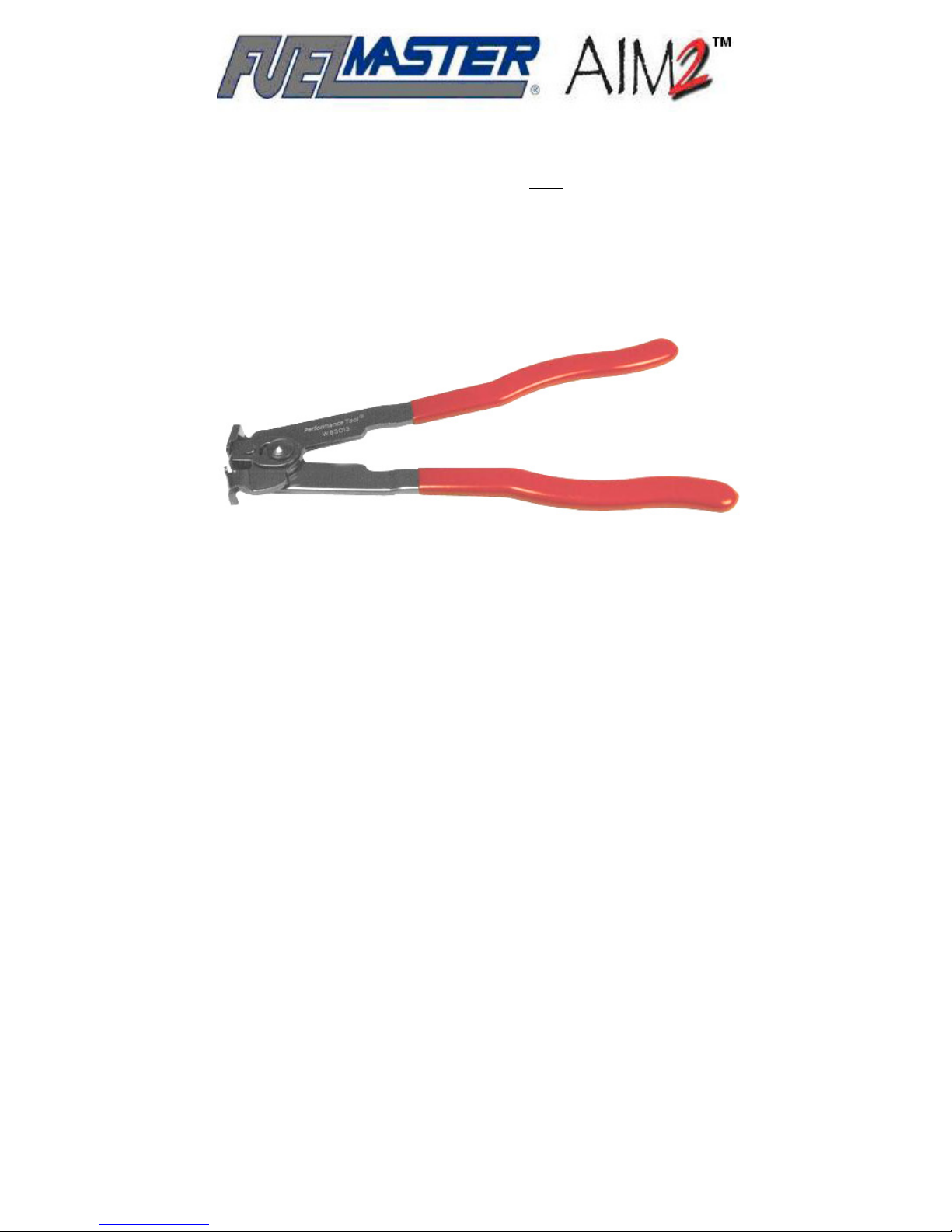
Figure 3-1. CV Joint Boot Clamp Pliers ..................................................................27
Figure 3-2. Sample Nozzle Tag Installation.............................................................28
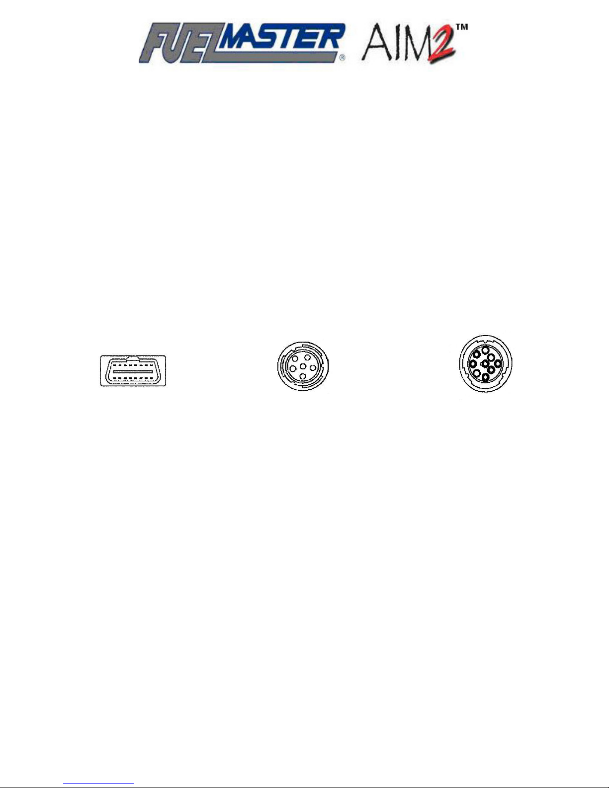
Figure 3-3. OBD Connectors ..................................................................................29
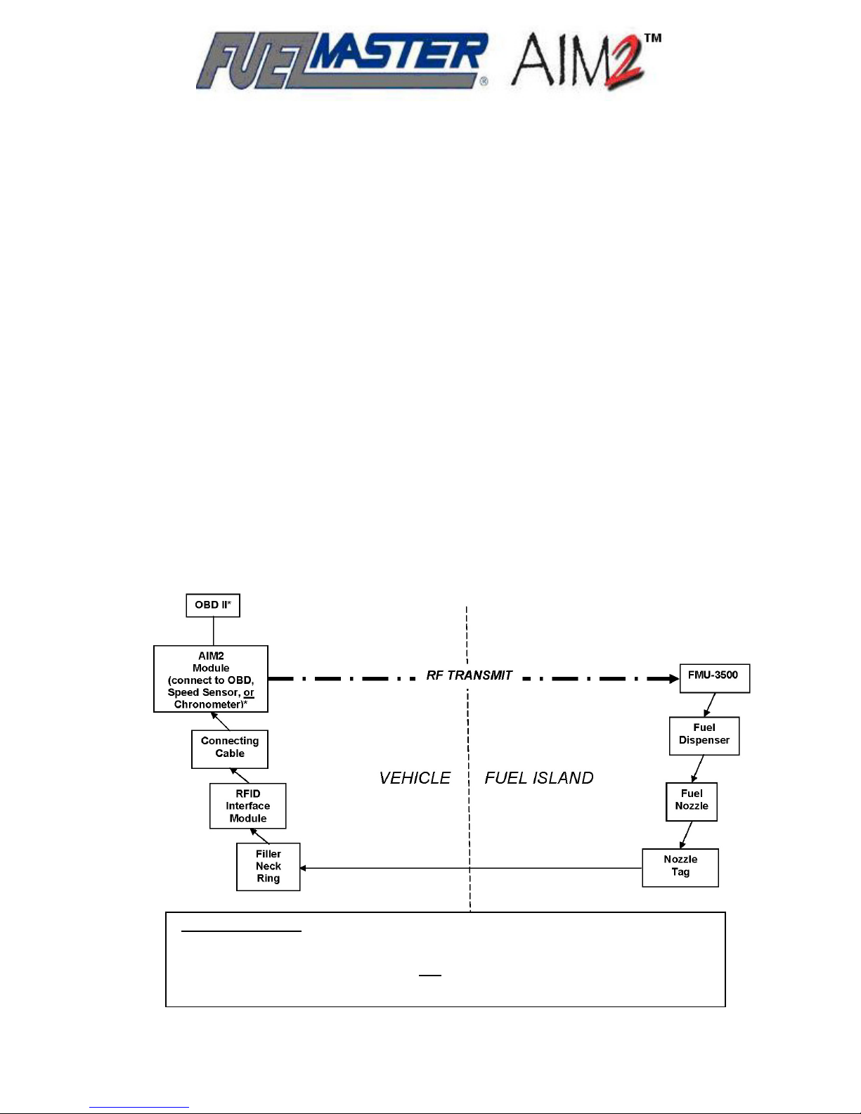
Figure 4-1. AIM2™ Connection – Flow Chart ..........................................................32
Figure 4-2. AIM2™ Module Layout .........................................................................33
Figure 5-1. 4x4 Keypad Shift Instructions ...............................................................46
APPENDICES
Access Point Installation and Setup Procedure ......................................................TBD
ATTACHMENTS
Acceptance Test Procedure (ATP) for Commercial Installations, Upgrades, Startup,
and/or Training of FuelMaster
Hold Harmless Agreement (blank)
AIM2™ Installation Notice
AIM2™ (blank)
®
AIM2™ Vehicle Installation Worksheet (blank)
6
Page 7

SECTION 1
GENERAL INFORMATION
Proprietary Information
This FuelMaster® AIM2™ Installation Manual is copyrighted 2009. Any unauthorized duplication,
distribution, or disclosure to third parties without specific written authorization from Syn-Tech Systems,
Inc., P.O. Box 5258, Tallahassee, FL 32314, is a violation of the law. FuelMaster
software are copyrighted 2009, and are provided under a license agreement containing restrictions on
its use. Except as stated in the license agreement, the firmware and software may not be copied or
distributed in any form or medium or disclosed to third parties. Users are legally accountable for any
violation of the License Agreement or of copyright law.
firmware and
®
Introduction
This manual provides installation and setup instructions for the Syn-Tech Systems, Inc., FuelMaster®
AIM2™ Automotive Information Module (herein referred to as AIM2™) and associated equipment.
These instructions have been prepared for the exclusive use of installation technicians who are
qualified to complete electrical work on vehicular electrical systems. AIM2™ consists of equipment
developed to initiate passive fueling through a FuelMaster
FuelMaster
FMU-3535 Passive Mobile Fuel Management Unit.
®
FMU-3500 Fuel Management Unit, or a
®
Passive fueling, as used in this context, is the initiation of a fueling transaction by the AIM2™
equipment without the need for operator input. The fueling customer pulls his/her vehicle up to the fuel
dispenser (or fuel truck), takes the fuel nozzle down from the dispenser, and inserts it into the vehicle
fuel filler neck. This action prompts the AIM2™ equipment in the vehicle to transmit authorization via
RF (radio frequency transmission) to the FuelMaster
fueling hose. When complete, the fueling customer returns the nozzle to the dispenser, returns to
his/her vehicle and drives away. The FMU-3500/3535 records the fuel transaction and stores the
fueling information until downloaded by the FuelMaster
FMU-3500/3535 which, in turn, activates the
®
Fuel Management Software operator.
®
Purpose
FuelMaster® fuel accounting and control provides Syn-Tech’s customers with a means to control
access to metered products at self-service service stations, and to account for and invoice for the
dispensed products. FuelMaster
maintaining complete accountability of each transaction as it occurs. FuelMaster
provides for secure, accountable control of fuel dispensing without direct user access of the fuel
management system. Transaction data is compiled after downloading data to a central accounting
office hundreds, or thousands of miles remote from the servicing operations.
accomplishes this with security from unauthorized user access while
®
passive fueling
®
7
Page 8

Safety Precautions and Corrective Actions
NFPA 70, the National Electrical Codes (NEC), define a fuel dispensing site as a hazardous location
and contains guidelines for the installation and operation of any equipment in such a location. NFPA
30, Flammable and Combustible Liquids Code, contains guidelines for electrical equipment and
installations in areas where Class I liquids are stored or handled, and where Class II or Class III
liquids may be stored at or above their flash points. The installer must be knowledgeable of these
and any other applicable safety codes and standards. All FuelMaster
complies with applicable federal, state, and local safety codes and standards.
This manual makes recommendations for commercially available equipment and materials that are
required to complete an installation. Trade names and part numbers are also referenced to cite
products that have been tested and known to be serviceable with passive fueling equipment.
Modification of the equipment provided, substitution of any material requirements, or any deviation
from these installation instructions must comply with all applicable safety codes and standards.
Use the following guidelines during installation and maintenance to help protect your passive fueling
equipment from potential damage and ensure your own personal safety:
Protecting Against Electrostatic Discharge
passive fueling equipment
®
Static electricity can harm delicate AIM2™ components. To prevent static damage, discharge static
electricity from your body by touching an unpainted metal surface before you touch any AIM2™
electronic components.
As you continue to work with AIM2™, periodically touch an unpainted metal surface to remove any
accumulated static charge. Use of a wrist-grounding strap is highly recommended.
The following steps should also be taken to prevent damage from electrostatic discharge (ESD):
• Keep a static-sensitive component in its antistatic packing material until ready for use. Just before
unwrapping the antistatic packaging, discharge accumulated static electricity by touching an
unpainted metal surface.
• Transport sensitive components in antistatic containers or packaging.
• Handle all sensitive components in a static-safe area. If possible, use antistatic floor pads and
workbench pads.
Correcting RF Interference
This equipment generates, uses and can radiate radio frequency energy and if not installed and
used in accordance with the instructions, may cause harmful interference to radio communications.
If this equipment does cause harmful interference to radio or television reception, which can be
determined by turning off and on the equipment, the user is encouraged to try to correct the
interference by one or more of the following measures:
• Reorient or relocate the radio/TV’s receiving antenna;
• Increase the separation between the equipment and the radio/TV’s receiver;
8
Page 9

• Connect the equipment into an outlet on a circuit different from that to which the radio/TV’s receiver
is connected; and,
• Consult the dealer or an experienced radio/TV technician for help.
Certification/Approval
The equipment supplied with AIM2™, FMU-3500, and FMU-3535 is tested and safety certified
by Intertek’s ETL SEMKO Division. Nameplates displaying the ETL logo are affixed to the AIM2™
module, FMU-3500, and FMU-3535.
WARNINGS, CAUTIONS, and NOTES
This manual emphasizes special operations with WARNINGS, CAUTIONS, or
NOTES preceding the applicable procedure:
• A
WARNING indicates a safety precaution that, if not followed, could result in personal
injury;
CAUTION indicates a safety precaution that, if not followed, could result in damage to
• A
equipment; and,
NOTE indicates a procedure requiring special emphasis for the proper installation and
• A
operation of Passive Mobile equipment.
FuelMaster® Warranty
The basic warranty on all FuelMaster® equipment begins 12 months after the completion of
initialization or 15 months after shipment from Syn-Tech Systems. Initialization must be completed
by a Syn-Tech Systems FuelMaster® technician, or a technician who has completed Syn-Tech
Systems installation certification training. Each Prokee® is warranted against defects in material and
workmanship for a period of five years. A toll-free number for technical assistance is also included.
This line affords the customer access to product support personnel who will answer questions
regarding operation of FuelMaster® hardware or software, and provide diagnostic capabilities when
necessary.
Under terms of this agreement, FuelMaster® technicians will telephonically diagnose problems, with
the assistance of the customer, to determine warrantable conditions, and possible problem
solutions. Syn-Tech Systems will replace all defective parts and provide assistance to the customer
in installation of replacement parts to allow the unit to be repaired as expeditiously as possible.
Please note that FuelMaster® was designed in a modular manner to provide easy and rapid
exchange of parts, even by non-technical personnel. Other systems are not designed this way and
consequently; do not offer warranties comparable to FuelMaster®. This warranty does not cover site
visits by FuelMaster® technicians for repair.
Please note that damage resulting from acts of god, user abuse, accidents, faulty installation or
operation is not covered under the warranty. This warranty specifically excludes any indirect,
special, or consequential damages to include, but not limited to, loss of product, profit, or litigation
fees. Additionally, associated equipment including printers, personal computers, and other items not
9
Page 10
manufactured by Syn-Tech Systems are warranted only to the extent covered by the original
manufacturer. Additionally, warranty is limited to approved locations (generally the continental
United States) and is not transferable except by written permission of Syn-Tech Systems.
Initialization Requirement
All FuelMaster® Fuel Management Systems must be initialized by Syn-Tech trained personnel.
Initialization is the startup inspection and tests performed to certify the installation. Initialization can
be completed only by a Syn-Tech FuelMaster® technician, or a technician who has completed
installation certification training for AIM2™. Final certification must be accomplished jointly by the
Customer and Syn-Tech trained personnel.
Safety Related Inspections and Preventative
Maintenance
AIM2™ requires no preventative maintenance to retain its user safety features. Whenever AIM2™ is
updated or repaired, a post-installation safety inspection should be performed of all wire connections
and hardware installations.
Consumables/Special Tools
Consumable/Special Tool Application
CV joint boot clamp pliers Crimp nozzle tag security clamps
Dielectric grease Prevent corrosion and protect electrical
connections exposed to the environment
12 AWG THHN stranded wire (Green) AIM2™ module ground wire(s)
Wire loom Cable/wire protection
Rubber grommets Protect cables/wires routed through drilled holes
Silicon sealant (GE blacktop/roof, 100% silicon) Seal grommets
Cable ties (black UV protected) Secure cables/wires
3M Scotch® Rubber Mastic Tape 2228 Weatherproof RFID Interface Module
18 AWG THHN stranded wire (Red, Black, Speed sensor wires
Green, White, Brown)
18 AWG THHN stranded wire (Orange, Analog chronometer wires
Blue)
AC power cord w/18 AWG conductors Power cable for FMU-3500 Programmer
and male plug
10
Page 11
Consumables/Special Tools (con’t)
Consumable/Special Tool Application
Tyco Electronics 1-480305 connector housing Power connector for FMU-3500 Programmer
Tyco Electronics 60618-4 contacts (3 each) Wire contacts in power connector for FMU-3500
Programmer
Improvements
Recommendations for improvement or corrections to this manual may be reported to Syn-Tech's
Product Support at 800-888-9136 (phone), 850-877-9327 (FAX), [email protected]
or by mailing to:
SYN-TECH SYSTEMS
Attn: Product Support
P.O. Box 5258
Tallahassee, FL 32314
11
Page 12

12
Page 13

SECTION 2
SYSTEM DESCRIPTION
Syn-Tech Systems, Inc. offers a passive fueling version of their world renowned Fuel Management
Unit (FMU). The FuelMaster
the addition of components required to facilitate passive operation. AIM2™ is the trademarked name
of Syn-Tech’s passive fueling system. The name AIM2™ is derived from the principle component of
the system, the second generation Automotive Information Module.
The installation procedures contained herein will only cover the taskings unique to AIM2™ passive
fueling, and any differences as they apply to FMU and software installations. Basic FMU installation
must be referred to the FMU-2500 Installation Manual. Software setup and operation must be
referred to the FMPlus User Guide.
Plus FMU-3500 is built on the widely accepted FMU-2500 platform with
®
FuelMaster® Passive Fueling
FuelMaster® passive fueling provides for secure, accountable control of fuel dispensing without the
need for user access of the FMU.
Vehicles (or other equipment items) and fuel island dispensers are fitted with passive fueling
equipment, and an FMU-3500 is installed to authorize and record fueling. The FMU-3500 links the
vehicle to the dispenser. Options are available to upgrade other existing models of FMUs to the FMU3500 configuration. It may not be necessary to purchase new FMUs to acquire passive fueling.
Typical Fueling Transaction: Automation and control are totally transparent to the fueling
customer in a typical AIM2™ fueling transaction. The fueling customer drives an AIM2™ equipped
vehicle up to the fuel dispenser, takes the fueling hose down, turns on the dispenser, inserts the fuel
nozzle into the fuel tank filler neck, and pumps fuel. When fueling is complete, the customer removes
the nozzle, turns off the dispenser, hangs the nozzle up, then returns to the vehicle and drives away.
Through this procedure, the passive fueling system has authorized the transaction, then recorded the
vehicle, quantity, product, hose, date, time, and odometer/chronometer reading at the time of the
transaction, and accomplished all this without user access of the FMU. Table 2-1 reflects additional
data which may be recovered by AIM2™ through an OBD II (onboard diagnostics) connection.
Availability of this data will be dependent upon the vehicle and its ability to generate the data.
Light/Heavy Duty is primarily to differentiate between the types of OBD connections available. As
shown in the table, Heavy Duty vehicles may generate more data.
Insertion of the fuel nozzle into the vehicle’s filler neck triggers the AIM2™ module (vehicle
transceiver) to send authorization information to the FMU. Upon receipt of an authorized input, the
FMU turns on the selected dispenser hose and records the fuel quantity pumped into the vehicle.
Removing the fuel nozzle from the vehicle’s filler neck ends the transaction. Fueling cannot be
resumed without reinserting the nozzle into an AIM2™ equipped vehicle, or by the user accessing the
FMU with an alternate access device (Prokee
Automated transactions may only be initiated by vehicles or access devices with the same Site
Signature (unique customer identifier) as the FMU controlling the fuel dispensers.
Passive fueling transactions may also record user identification through keypad entry at the FMU, or
by passing a proximity card across the optional Proximity Card Reader.
, Smartcard, credit card) or keyless configured entry.
®
13
Page 14
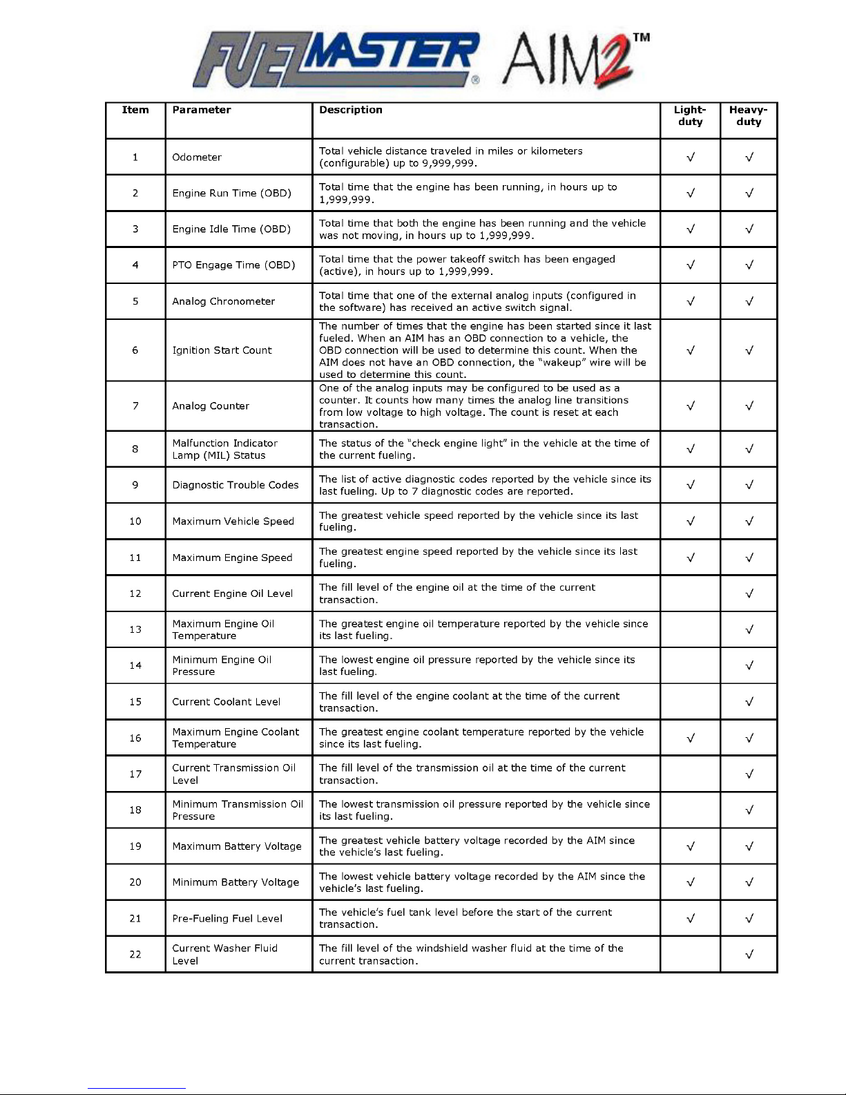
Table 2-1. AIM2™ OBD Data Collection Parameters
14
Page 15
Installation Requirements
AIM2™ fueling system entails software installation, FMU installation, then AIM2™ module installation
and programming. AIM2™ programming is required, but cannot be performed until the software is
installed and databases are developed, the FMU is installed, and the AIM2™ modules are installed in
the vehicles.
Although not absolutely required, Syn-Tech Systems recommends installation of the FMU-3500 and
Central Controller initially for use with a direct access device such as a Prokee
card, or Keyless entry. This permits the development of the required databases, and installation of
the AIM2™ modules in preparation for passive fueling. As the AIM2™ modules are installed, the
other interfaces will already be in place to bring passive fueling online.
: The normal sequence of events to complete the installation of an
, Smartcard, credit
®
Components of a Passive Fueling System
FMU-3500 and FMU Upgrades. The FMU-3500 is an FMU-2500 equipped for passive
fueling. FMUs of other configurations may be upgraded to FMU-3500 to gain passive fueling
capabilities. The FMU-3500 will have a backup function for user access with a Prokee
Smartcard, magstripe card, or through Keyless transaction entry. Features which make an FMU3500 compatible with passive fueling are:
Firmware Version
,
®
Power LED
Channel A Receive LED
Channel A Transmit LED
Channel B Receive LED
Channel B Transmit LED
Channel A
Channel B
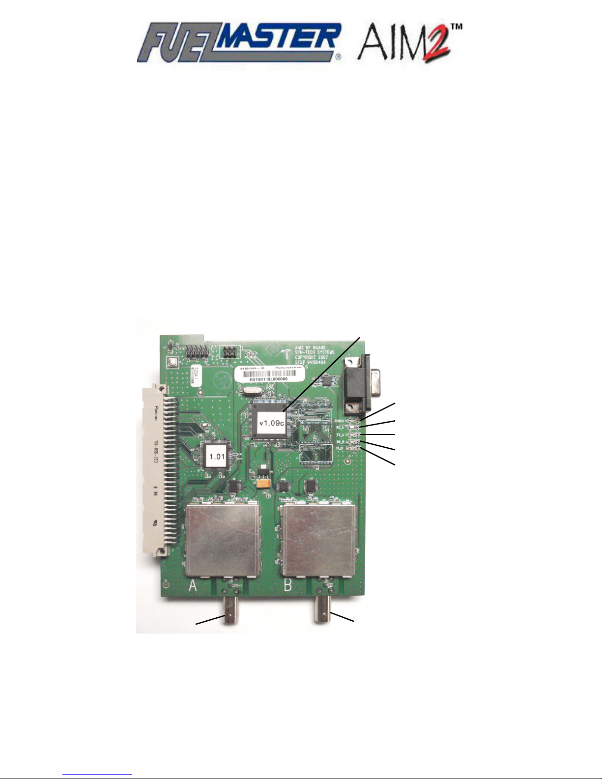
Figure 2-1. FMU Radio Board (FRB)
• An FMU Radio Board (FRB) which functions as a transceiver to receive inputs from, and send
programming information to AIM2™ equipped vehicles and equipment. The FRB includes A
15
Page 16
and B channel outputs/inputs, and five LEDs: a red, steady Power LED, and four green,
flashing transmit/receive LEDs as shown in Figure 2-1.
• Two 926 MHz antennas for receiving RF transmissions from the AIM2™ module. These
antennas may be attached to the FMU, or external (remote) antennas may be installed to
ensure best possible RF coverage. The antennas are connected internally to the FRB.
External antennas may be necessary when an FMU is physically separated from line-of-sight
with the fueling vehicles. The external antennas may be used to restore line-of-sight to the
fueling vehicles. External antennas installed under a roof or higher than FMU height should be
installed horizontally instead of vertically. The two antennas should be spaced 8 inches (or in
multiples of 8 inches) apart.
• Quad UART board to control a second FRB when a secondary application requiring directional
antennas (for Access Point) is needed.
• A Compact Flash Card for operating and programming memory. It is absolutely necessary for
FMU-3500 functions. The compact flash card is now standard in all FMU-2500 series units.
Some older FMU-2500 units being upgraded to FMU-3500 may require a newer revision
mainboard to accept and correctly read compact flash cards.
FMU-3535 Passive Mobile. The FMU-3535 Passive Mobile is an FMU-3500 adapted for
mobile use on tanker trucks. The FMU-3535 provides a mobile capability for fueling AIM2™
equipped vehicles or equipment which may not be able to return to a service station for fueling.
Passive Mobile installations are covered in a separate installation manual.
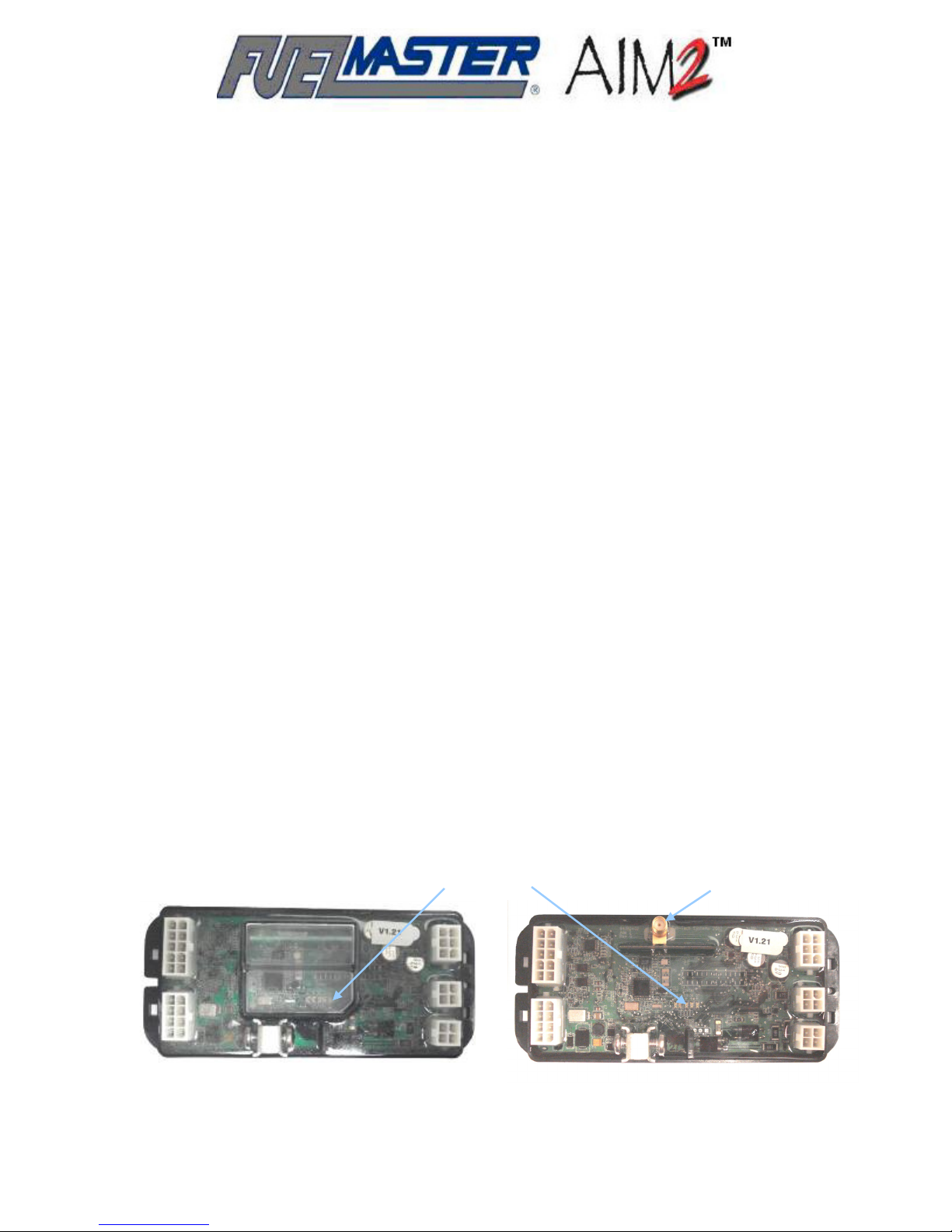
Automotive Information Module. The Automotive Information Module (see Figure 2-2) is
an intrinsically safe vehicle mounted transceiver/computer which stores vehicle information and
communicates with the FMU to authorize fueling hoses and receive programming information. The
standard module (part number 941B0420A) has an internal antenna and is suitable for most
applications. When necessary, an external antenna may be installed and connected to part
number 941B0420B AIM2™ modules. 941B0420A modules do not have external antenna
connections. 941B0420B modules do not have internal antennas. External dimensions of both
modules are approximately 5-5/8 inch long x 2-3/8 inch wide x 1 inch high. Acceptable input
power is 12 VDC to 42 VDC. AIM2™ modules draw 0.4 amps when active, and 0.0134 amps in
sleep mode. The AIM2™ module is designed for operation in temperatures ranging from -60 to
+140 degrees F.
Indicator LEDs
External Antenna
Connector
941B0420A 941B0420B
Figure 2-2. AIM2™ Modules
16
Page 17

AIM2™ modules may receive odometer and chronometer inputs through an OBD II connection, or
through analog speed sensor and analog chronometer inputs. Power for the AIM2™ module may
be supplied either directly through the OBD II connection, or through an analog speed sensor
cable. The chronometer cable does not make power connections.
Amber, Yellow, Green, and Red indicator lights (LEDs) are built into the center top surface of the
AIM2™ module for feedback of operating and programming conditions. These LEDs must remain
visible after installation for testing and troubleshooting.
AIM2™ modules go to “sleep” (become idle and operate on reduced input power) 2 minutes after
the vehicle ignition is turned off or, if within communications range of an active FMU-3500, 15
minutes after the vehicle ignition is turned off. The module must be “wakened” before fueling may
occur. Turning on the vehicle ignition or starting the engine will waken the module.
AIM2™ modules have three possible interface settings or states: NONE, OBD, or SPEED
SENSOR. NONE is the default. When the module is set to NONE, it will not go to sleep. OBD and
SPEED SENSOR indicate an OBD or analog connection. When connected to an OBD connector,
an AIM2™ module will detect OBD and change state as soon as the vehicle is turned on. When
connected to a SPEED SENSOR, the AIM2™ module will not change state until the vehicle starts
moving. Reefers require the engine to be started after installation to change state.
AIM2™ Module External Antenna. The AIM2™ module has to communicate with the FMU
FRB. Some vehicle mounting applications may not readily support communications between the
AIM2™ and FMU. In these instances an external antenna may be mounted on the vehicle and
connected to the AIM2™ module to ensure RF coverage. Syn-Tech has external antenna kits
available with 13 or 20 foot long cables, mount brackets, and the necessary fittings to connect to
AIM2™ modules equipped to accept external antenna connections.
Access Point. An Access Point is a device developed solely to control gate/door/carwash
access or
description and installation procedures for an Access Point may be found in Appendix A to this
manual.
AIM2™ Programming Key. A Prokee
Programming Key will only permit programming of an AIM2™ module.
monitor vehicle movement via RF transmission from an AIM2™ equipped vehicle. A full
/Smartcard with special application; an AIM2™
®
Nozzle Tag (sometimes referred to as Hose Tag). The Nozzle Tag is an intrinsically safe device
installed on the fuel dispenser (or Passive Mobile) fueling nozzle to initiate a passive fueling
transaction. The Nozzle Tag contains an antenna coil and RF/ID chip programmed with a number
to identify the fueling nozzle it is attached to. Unique to FuelMaster
require a cable routed down or through the fueling hose for power. Nozzle Tags are available in a
variety of sizes and shapes to accommodate most known fuel nozzle types. Figure 2-3 is an
example of a nozzle tag. Table 2-2 is a listing of nozzle tags in production at the time of this
writing. Additional nozzle tags may be developed as the need arises. Table 2-3 is a listing of CV
(constant velocity) boot clamps offered by Syn-Tech Systems to secure the nozzle tag to the fuel
nozzle. Table 2-3 also lists a kit part number which contains the more popular nozzle tags with a
CV boot clamp.
, the Nozzle Tag does not
®
Programming Hose Tag (PHT). A specially programmed nozzle/hose tag used to identify
vehicles when programming. These are identified with an attached label containing a letter (one letter,
17
Page 18
A through F). Each FMU may be configured to use a single PHT. A PHT is needed to complete the
programming interface between an AIM2™ module and the FMU. PHTs are made from operational
nozzle tags which closely match the application in which they are used.
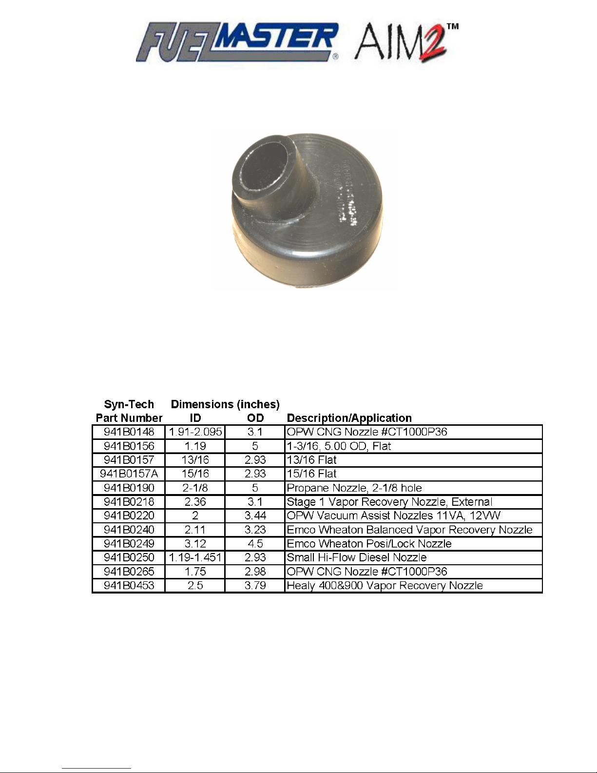
Figure 2-3. Sample Nozzle Tag
Table 2-2. Nozzle Tag Applications
18
Page 19
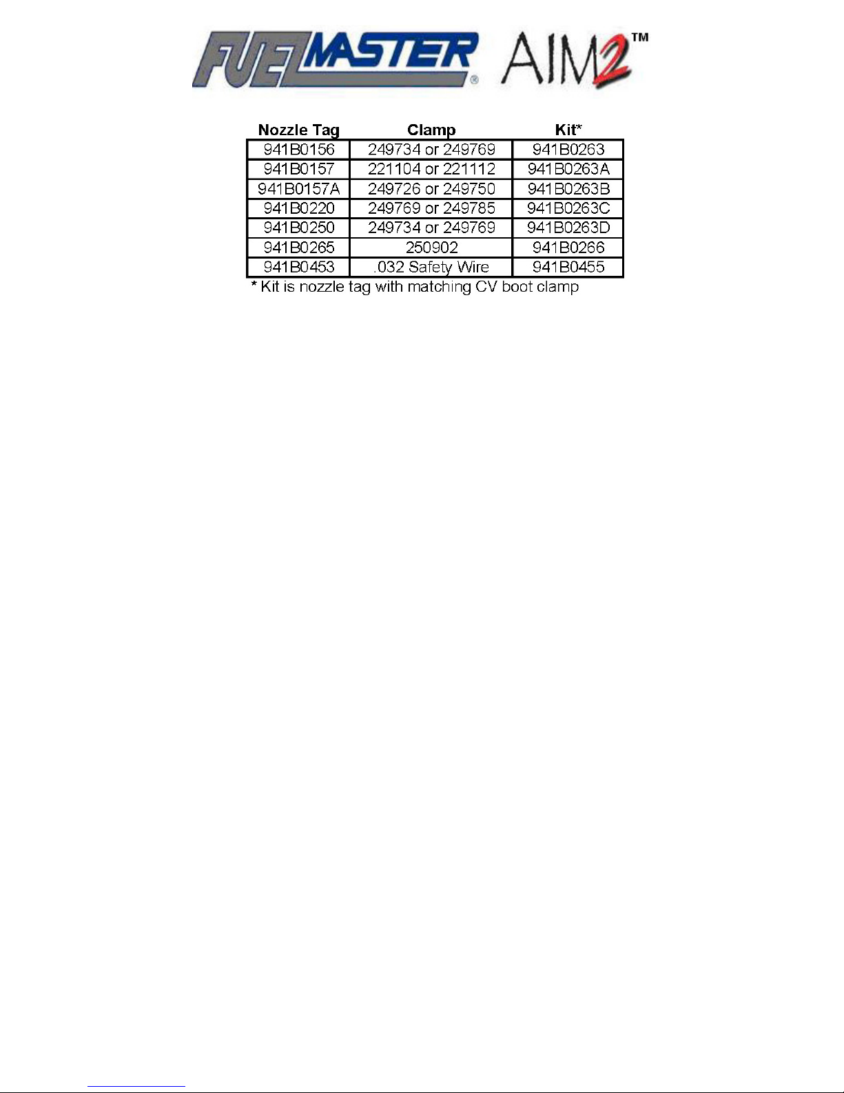
Table 2-3. Nozzle Tag Clamp and Kit Part Numbers
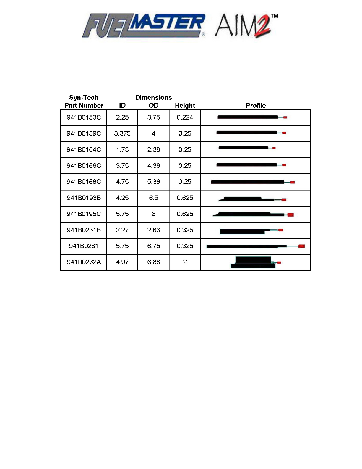
Filler Neck Rings/RFID Interface Module. Like the nozzle tags, filler neck rings contain
an antenna coil and RF/ID chip for communications with the nozzle tag. The filler neck ring has a
48 inch pigtail for connection to the RFID Interface Module (also referred to as Lump Board). Filler
neck rings are available in a variety of sizes for installation on a variety of vehicle fuel tank filler
necks (see Table 2-4 for a breakdown of sizes, profiles, and pigtail lengths). Filler neck rings may
be glued in place with a gasoline and oil-resistant adhesive such as Seal-All from Eclectic
Products, Permatex or 3M Super Weatherstrip adhesive, or Gorilla Glue (for rough surfaces). If
you cannot find one of these adhesives, try to find something with similar properties which is gas
and oil-resistant, and will not damage the rubber surface of the filler neck ring. Lipped filler neck
rings may also be tacked in place with screws if care is taken not to contact the internal coil of the
filler neck ring.
The RFID Interface Module generates the signal for the filler neck ring to communicate to the
nozzle tag. When the nozzle tag is brought close enough to the filler neck ring, information (hose
number) in the nozzle tag is received by the filler neck ring and transmitted through the RFID
Interface Module and RFID Extension Cable to the AIM2™ module. Early variations on the RFID
Interface Module had connectors exiting straight out of the end of the module. Current versions of
the module have connectors positioned at right angles to the module. There are also some newer
variations with clear (instead of black) potting. Figure 2-4 illustrates a sampling of the vehicle
components which complete the connections from the filler neck ring forward to the AIM2™
module.
Connecting Cables. The AIM2™ module receives connections from an assortment of cables
designed for the application. RFID Extension Cables connect between the RFID Interface Module
and AIM2™ module, and are available in 15, 20, 30, 50, and 80 foot lengths. Connections through
the OBD port provide information and power to the AIM2™ module. Figure 2-5 is of an OBD II light
duty connection cable with a pass-thru connector which allows for connection of an OBD
diagnostic tester without disconnecting AIM2™. Other cables are available for other types of OBD
connections.
Cables for analog connections to a speed sensor or chronometer have pigtails for the necessary
connections. Analog chronometer connections do not connect to vehicle power. AIM2™ module
power must be derived from an OBD or speed sensor cable connection.
19
Page 20
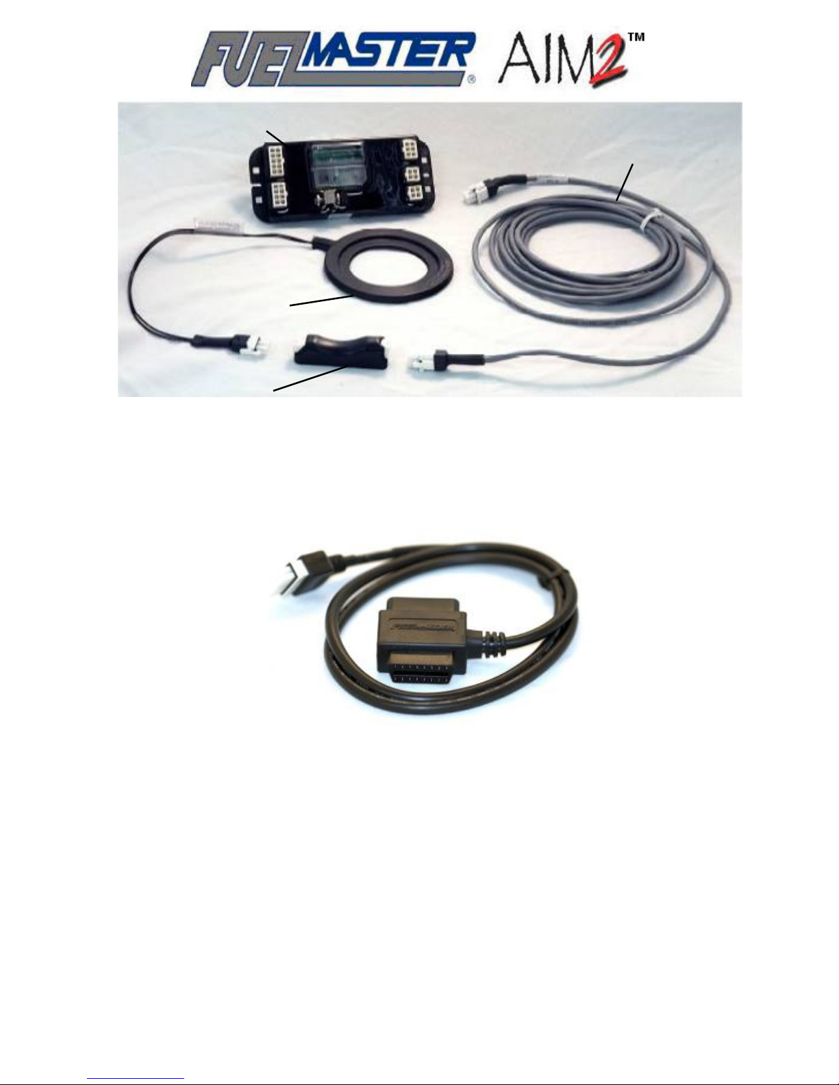
AIM2™ Module
Filler Neck Ring
RFID Extension Cable
RFID Interface Module
Figure 2-4. AIM2™ Vehicle Components
Figure 2-5. OBD II Pass-Thru Cable
A chronometer need not be a physical device added to the vehicle/equipment to attain the desired
information. A chronometer input may be as simple as a power source which is only powered
under special circumstances. Engine runtime may be a power source which is only supplying
power when the engine is running; PTO (power takeoff) engage time may be a power source
which is only supplying power when the PTO is engaged. Chronometer inputs may be from as
many as three different sources: through the OBD connection and up to two analog chronometer
inputs, to record vehicle run and idle time, and PTO time.
Cables are available for combining two separate fuel tanks and their filler neck rings into one
AIM2™ module. When this is done, fillups to either tank are recorded. When the transactions are
downloaded into the software, the vehicle record has only one tank record so transactions from
20
Page 21
both vehicle tanks are combined to look as if one tank was filled.
Reefer applications may require special consideration before installations begin. Reefers may
draw from the same fuel tank as the truck, or fuel consumption may be separately tracked through
the use of its own AIM2™ module when a separate fuel tank is installed.
Table 2-4. Filler Neck Rings
21
Page 22
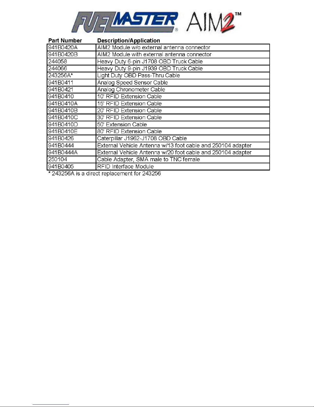
Table 2-5. Connecting Cables and Devices
22
Page 23

SECTION 3
SYSTEM PLANNING
With a passive fueling system there is much more to consider than the basic FMU connections to
power, dispenser pulse and control, and Central Controller communications. For an FMU-3500 to
turn on a fueling hose when the nozzle is inserted into the vehicles filler neck, two additional
communications functions must perform satisfactorily. First, the nozzle tag must communicate with
the filler neck ring to initiate a transaction and, secondly, the AIM2™ module must communicate with
the FMU to activate the transaction.
NOTE
A vehicle/equipment listing is requested from new customers planning AIM2™ installations. Syn-Tech
Systems will review the listing and select the nozzle tags, filler neck rings, and connecting cables
required to outfit the vehicles and equipment items.
System planning involves the following considerations:
1. Review of the “Fundamental Do’s/Don’ts” which follow these considerations;
2. Developing a database of vehicle records for each vehicle/equipment item receiving AIM2™;
3. Selection of the correct nozzle tag;
4. Selection of a filler neck ring compatible with the vehicle and nozzle tag;
5. Selection of the proper length RFID Extension Cable to connect between the RFID Interface
Module and AIM2™;
6. Selection of the correct interfacing cables to connect the AIM2™ module to the vehicle OBD,
analog speed sensor, and/or analog chronometer;
7. Examination of the vehicles/equipment items receiving AIM2™ to determine if external
antennas will be required; and
8. Selection of a suitable mounting location for the FMU where it can communicate to all the
passive-equipped vehicles fueling through it. If such a location is not available, are there
locations available for mounting external FMU antennas?
Insufficient consideration of any one of these functions will return poor performance from the passive
fueling system.
Fundamental Do’s/Don’ts
There are fundamental key points which must be considered for installation success. Follow these
crucial Do’s/Don’ts closely when planning your AIM2™ installation:
Don’ts
Don’t mount the FMU/FRB antenna in a kiosk. RF transmission will be blocked, or range will be
greatly reduced. If the FMU is already installed in a kiosk, install FMU external antennas so the
vehicle/equipment can communicate to the FMU with direct line-of-sight.
23
Page 24

Don’t mount the FMU/FRB antenna close to a metal overhead or wall. RF range will be reduced.
Don’t mount the FMU/FRB antenna around the corner of a building or an aboveground
storage tank. RF will be blocked, or range will be greatly reduced. The RF transmission is most
effective when there is line-of-sight between the FMU and fueling vehicle.
Don’t mount AIM2™ modules in a metal or fiberglass box. AIM2™ modules have built-in
antennas and are designed to communicate directly with passive FMUs. RF transmission will be
blocked or greatly reduced if installed in a metal or fiberglass box. If it is absolutely necessary to
mount the AIM2™ module inside a metal or fiberglass enclosure, plan on using an external AIM2™
antenna.
Don’t expect fueling to occur if there is any obstruction (semi, bus, ready-mix truck, etc)
between the FMU and vehicle. There will be no link between the FMU and vehicle. RF will be
blocked, or range will be greatly reduced. The RF transmission is most effective when there is lineof-sight between the FMU and fueling vehicle.
Don’t expect more than about 50 feet communication range between the FMU and vehicle in
most fuel island scenarios. AIM2™ was designed to transmit between a vehicle at a fueling point,
and the FMU controlling that fueling point. Typically this distance is limited by the size of the fueling
island. Some minor range extensions may be expected when using external AIM2™ and/or FMU
antennas. Installation costs may be minimized by planning for a 50 foot communications range, and
deferring the installation of external antennas.
Don’t expect satisfactory operation from all in-vehicle under-dash installations. Some will
require the AIM2™ module to be mounted in a less obstructed area. Some will require
connection to an external antenna. Some under-dash installations may not allow RF
communication with an FMU. Should this occur, move the AIM2™ module to another location with
less obstruction, or install an external antenna.
Don’t expose the AIM2™ module to road debris, gasoline, ozone, freezing rain, road salt, UV
radiation, and human abuse. The AIM2™ module can survive the same temperatures as the
vehicle, but service life will be greatly shortened by exposure to the environment.
Don’t expect consistent filler neck ring antenna to RF/ID nozzle tag communication if the
range is more than a couple of inches. The nozzle tag and filler neck ring are tuned to
communicate with each other at a distance of two inches or less, and to terminate the transaction
when the nozzle is removed from the filler neck.
Don’t install nozzle tag behind/above splash guard. A splash guard will block nozzle tag RF
connection to filler neck ring.
Don’t expect all vehicles to be OBD II compatible even if they have an OBD II connector.
Some vehicles may have multiple OBD connectors, some of which will not power the AIM2™
module. Some vehicles will have an OBD connector and use an analog speedometer or
chronometer.
Don’t expect all nozzles to be RF/ID Tag compatible. Interfaces have been made to a wide
variety of nozzles, but new nozzle types still appear. If the nozzle is not common and listed in Table
2-2, call your FuelMaster
regional sales manager or distributor. Custom applications have been
®
made for unique fueling nozzles.
Don’t complete all your vehicle and FMU installations before testing the system for
satisfactory operation. If some error has been made in the installation of any of the equipment,
don’t wait until all the installations are complete to find out. Test some newly installed vehicles to
verify satisfactory performance. Whenever a new installation is performed on a new type vehicle or
with a new cable, test the installation before proceeding with similar installations.
24
Page 25

Don’t expect all downloaded transaction data to be perfect. Improper initial configuration of the
FMUs or AIM2™ modules may result in incorrect data. This is verified by post-installation tests
performed in accordance with the Acceptance Test Procedure (ATP) provided in the back of this
manual.
Don’t let vehicles sit for extended periods of time without charging the battery. An AIM2™ is
another vehicle accessory drawing approximately 30 milliamps. Extended periods of inactivity
without charging the battery may draw the battery down.
Don’t expect nozzle tags to last forever. Continued exposure to fuel, ozone, the sun’s radiation
and human contact will, over time, cause the material to break down.
Do’s
Do mount an FMU on each fuel island. AIM2™s were designed to transmit 50 feet between a
vehicle at a fueling point, and the FMU controlling that fueling point. Fueling vehicles on islands
where there are no passive FMUs results in extended RF range, and continual vehicle movement
between the islands, both of which will degrade RF performance.
Do consider remote, external antenna configurations for both the vehicle and FMU where
existing conditions may limit RF performance. These antenna options may be used to increase
range.
Do request assistance with scenarios requiring more than 50 feet of FMU to vehicle range.
Our experience could save a lot of time and expense with scenarios which may not match the
requirements listed herein. Discuss with your FuelMaster
regional sales manager or distributor.
®
Do protect environmentally exposed AIM2™ modules. If the only available enclosure on the
vehicle or equipment is metal or fiberglass, purchase an inexpensive weatherproof plastic box to
house the AIM2™ module, or mount the module in the existing metal or fiberglass enclosure and
use an external antenna for RF communications.
Do insure the filler neck ring is mounted as close as possible to the top of the filler neck, and
is secured in place. The filler neck ring is an antenna which must remain within two inches of the
nozzle tag when a fuel nozzle is inserted into the filler neck.
Do install, configure and test vehicle installations individually. The basic principles of
troubleshooting prevail. If a problem appears you want the problem limited to the fewest probable
causes.
Do check the transaction data downloaded from the FMU. Downloaded transaction data may be
used for invoicing, tax purposes, and verifying credit card transactions. Proof the downloaded
transaction data to verify it remains accurate. Retail transactions should especially be monitored to
keep pricing current with fuel costs, and to ensure download quantities match pumped quantities.
Do read FMU-2500/3500 and Passive Mobile Installation and User Manuals. FMU, Passive
Mobile, and software installation and operation instructions are incorporated in other, separate
manuals.
Do insure FMUs are configured correctly. FMUs may be configured from either the FMU or the
Central Controller. They may also be reconfigured with incorrect data from either the FMU or
Central Controller. It’s a good practice to make a backup paper copy of a known good configuration
report.
25
Page 26
Version Compatibility
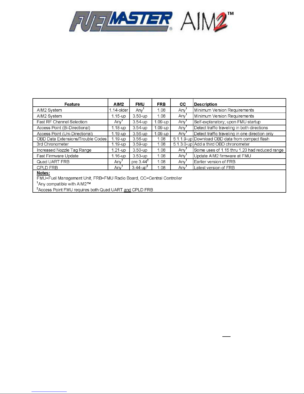
As AIM2™ has evolved, enhancements were introduced in a specific version of the hardware,
firmware, or software. If problems are being experienced, or if a specific feature or option is not
available, it may be because the current version of the hardware, firmware, or software being used is
not compatible with another system component, or does not contain the desired feature or option. See
Table 3-1 for a list of version compatibilities.
Table 3-1. Version Compatibillity
Developing a Database of Vehicle Records
The Central Controller must be set up and the Fuel Management Software installed in accordance
with the FMPlus User Guide. Particular attention should be given to selecting AIM2™ as the passive
system type so the software will prompt for the correct information as the database is developed. The
chapter covering AIM2™ Software Operations must be followed and all procedures performed to
properly set up the vehicle records needed to program the AIM2™ modules.
If an upgrade is being performed and the software was previously set up for a non-passive system,
the software may be reconfigured to develop vehicle records for an AIM2™ passive system. In the
FMPlus User Guide, refer to System Configuration, Passive System Type. This paragraph will
describe what is necessary to change the program to an AIM2™ passive system program which will
allow for the development of vehicle records for programming AIM2™ modules.
Once developed, the vehicle records for the AIM2™ equipped vehicles are uploaded to the FMU
selected to be the programming FMU. See AIM2™ Programming after Installation.
Selecting the Correct Nozzle Tag
The nozzle tag must fit on the dispenser fueling nozzle. When the nozzle is inserted into the vehicles
fuel tank filler neck, the nozzle tag must be within two inches of the filler neck ring, preferably closer,
or touching, and the two devices should be parallel to each other. Being within 2 inches on one side
and 3 inches on another side will not initiate communications. This alignment has
initiate a fueling transaction. The nozzle tag is programmed with a hose number corresponding to a
specific product. The nozzle tag will mark the transaction with the hose number and corresponding
product pumped during a transaction.
to be correct to
The nozzle tag has no wire connections to the fuel dispenser or vehicle. It is totally independent. This
26
Page 27
means it can perform its function on or off the fueling nozzle. If the nozzle tag is not secured to the
nozzle, the nozzle tag may be removed and placed next to a filler neck ring of any vehicle with an
authorized AIM2™ module. This will actuate the hose the nozzle tag was removed from permitting it
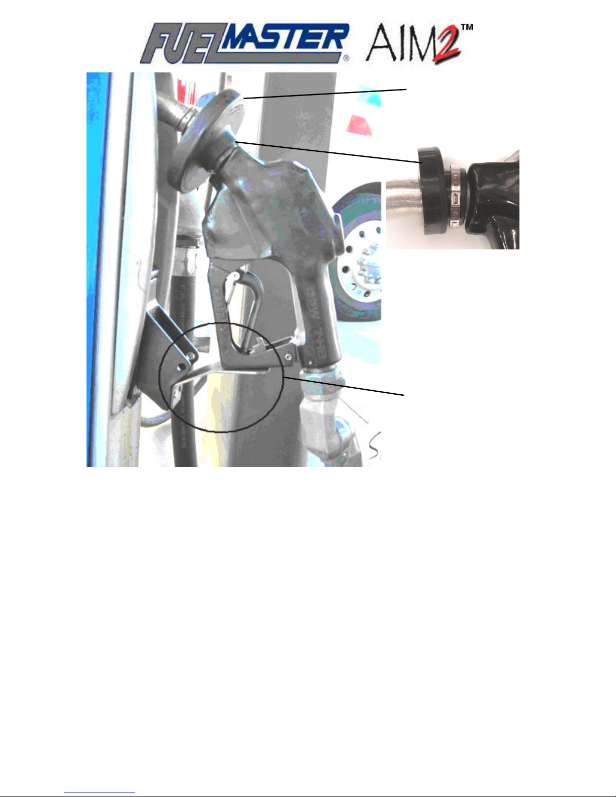
to fuel anything the nozzle is inserted into. Installation must
Nozzle tags should be secured to fueling nozzles by placing a clamp around the nozzle tag as shown
in Figure 3-2. CV joint boot clamps which require a special tool for installation provide the best
security because of their difficult removal. Kits are available through Syn-Tech Systems which
contain some of the more common nozzle tags and a CV joint boot clamp (see Table 3-1). CV joint
boot clamp pliers (Figure 3-1) are required to install these clamps, and are available through any
automotive parts outlet.
provide for security of the nozzle tag.
Figure 3-1. CV Joint Boot Clamp Pliers
Nozzle tags have been developed for a wide variety of fueling nozzles to include Stage 1, Stage 2,
vacuum assist, and balanced vapor recovery, Emco Wheaton Posi/Lock, Healy EVR, and others.
Nozzle tags may be cross-referenced to the fueling nozzle being used. Use Table 2-2 to select a
nozzle tag for the fueling nozzle in use.
Nozzle tags may prevent the normal hang-up of the fueling nozzle after the transaction is complete.
Figure 3-2 also shows an example of a Nozzle Hang-up Extension installed to permit the nozzle to be
hung up on the dispenser after a nozzle tag is installed. The extension shown was manufactured by
the customer. We are not aware of any nozzle hang-up extensions commercially available for this
application.
Selecting the Correct Filler Neck Ring and RFID
Extension Cables
Filler neck rings must 1) fit around the filler neck of the fuel tank, 2) allow the filler cap to be installed,
3) permit the nozzle tag on the fuel nozzle to be brought up against (or parallel within 2 inches) of the
filler neck ring, and 4) connect to the RFID Interface Module (Lump Board) installed in a protected
mounting location. All this must be considered when selecting the correct filler neck ring.
The appropriate RFID Extension Cables in the correct length must be selected to connect between
the RFID Interface Module and the AIM2™ module. It may be prudent to opt for a longer cable if the
needed length is close to one of the cable lengths. All the AIM2™ vehicular equipment may one day
be transferred to another vehicle, and the additional length may be needed. RFID Extension Cables
should not be extended or spliced.
27
Page 28
Nozzle Tag
(example, without
security clamp)
Security
Clamp
Installation
(example)
Nozzle
Hang-Up
Extension
(example)
Figure 3-2. Sample Nozzle Tag Installation
A list of vehicles is sent to Syn-Tech Systems when new passive fuel systems are purchased. SynTech reviews the list and selects the appropriate filler neck rings and connecting cables best suited
for the vehicles. For other requirements, refer to Table 2-4 to select the correct filler neck ring, and
Table 2-5 to select suitable connecting cables/devices.
Selecting the FMU Mounting Location
In addition to the need for dispenser control, a passive FMU-3500 also needs to be positioned where
it can communicate to all the vehicles being fueled through it. Communications to the vehicle is to the
AIM2™ module which is not usually mounted within direct sight of the FMU. The AIM2™ module is
often installed under the vehicle dash or in some kind of weatherproof compartment to protect it from
the elements.
When using the standard antennas provided with the FMU, the FMU-3500 should be mounted within
40-60 feet of the vehicle fueling positions. If traffic is continually moving between the fueling vehicles,
or if the FMU is inside a building or behind a wall, external antennas may be installed to restore the
line-of-sight.
28
Page 29
Identifying the Vehicle Application
NOTE
The vehicle/equipment manufacturers have no obligation to inform Syn-Tech Systems of changes
they make to their products. Consequently, it is very possible new vehicles or equipment may
incorporate changes unknown to Syn-Tech Systems which are not compatible with AIM2™. If you
find changes incompatible with AIM2™, inform Syn-Tech’s Customer Satisfaction Center or your
FuelMaster
make AIM2™ operable with the changes.
Light duty general purpose vehicles (sedans, vans, pickups) manufactured since 1996 have an OBD
nd
generation on-board diagnostic) port. Heavy duty vehicles with on-board diagnostics have a
II (2
different protocol resulting in a different type connector. The connector style will determine the cable
necessary to connect the AIM2™ module to the vehicle. The cable provided must plug into one of the
connectors illustrated in Figure 3-3. These vehicles power the AIM2™ module through this diagnostic
connection.
Some heavy duty vehicles may have multiple data ports. To determine which port to use, connect a
compatible cable between the data port and the AIM2™ module. A yellow OBD Connect light will
illuminate when an active port is connected, and the vehicle ignition is switched on.
representative (regional sales manager or distributor) and every effort will be made to
®
Light Duty
Pass-Thru;
243256A
With
Use
Cable
Heavy Duty
J1708
6-Pin;
Use
244058
Cable
Heavy Duty
J1939
9-Pin;
Use
244066
Cable
Figure 3-3. OBD Connectors
Most vehicles manufactured prior to 1996, and other vehicles which do not have computers, may
require AIM2™ connection to an analog speed sensor or chronometer to recover vehicle mileage or
operating hours. Some vehicles with computers may also have cable driven speedometers. If a
speed sensor or chronometer is not installed, it may be provided with the purchase of the other
AIM2™ equipment. Connection through a speed sensor or chronometer requires a connection to an
external power source. AIM2™ may be powered by any power source from 12 to 42 VDC. Two
connections are required: one to an unswitched power source, and another to a switched power
source powered through the ignition switch.
The AIM2™ module need not be heated for protection from the cold, but it must be installed where it
will not be exposed directly to the weather. It is not weatherproof. If the vehicle requires the AIM2™
module to be installed inside a metal box for protection from the weather, an external antenna should
be considered. AIM2™ modules are available with an external antenna connector, and external
antennas are available through Syn-Tech Systems to function with the AIM2™ module in closed
mounting applications.
29
Page 30

30
Page 31

SECTION 4
AIM2™ INSTALLATION
Installation requirements are coordinated with the purchasing customer when the sale is made. A
complete passive fueling system requires the installation of the FMU, all AIM2™ vehicle equipment,
and a Central Controller. Installation of the FMU and Central Controller may be accomplished by
anyone qualified, and must be installed before installation of the AIM2™ vehicle equipment. FMU
installation is performed in accordance with the FMU Installation Manual. Basic software (Central
Controller) installation is performed in accordance with the FMPlus User Guide.
The AIM2™ vehicle equipment installation may be accomplished by the customer (or their
representative) or Syn-Tech Systems. Most customers have their own mechanics, and the
mechanics are trained to perform their own AIM2™ vehicle installations. This can be of great
advantage to the customer. Their passive systems may be removed and reinstalled as vehicles are
replaced without seeking outside assistance. When the customer chooses to install their own vehicle
equipment, Syn-Tech Systems or one of their qualified distributors provides installation training to
the customer’s mechanics.
Some additional things to consider in your AIM2™ installations:
• The FMU FRB will not find the correct radio channel to communicate with the AIM2™ module
until the hoses are configured.
• The AIM2™ module uses RF technology to communicate with the FMU. If the AIM2™ module is
fully enclosed in metal or fiberglass enclosures it may not communicate with the FMU unless an
external antenna is connected to the AIM2™ module. Most vehicle installations will not require
an external antenna.
• If more than one OBD connection is available in the vehicle being installed, the serviceability of
the connection may be tested by making a connection to the vehicle OBD connector and turning
the vehicle ignition switch on. If the connection is serviceable, a yellow OBD connect light will
illuminate on the AIM2™ module.
• If an installation is being made in a vehicle with a cable driven speedometer (no OBD
connection), a transducer may be required to send vehicle speed data to the AIM2™ module.
Syn-Tech Systems does not stock transducers for these installations. Consult a parts distributor
for the make of vehicle under consideration.
• Installations will vary from vehicle-to-vehicle by year, make, and model. Do not assume an
installation will work without testing if similar installations were performed on similar vehicles.
Changes have been seen between two vehicles of the same make, model, and year.
• Do not install any AIM2™ components within close proximity of hot or moving vehicle parts.
• AIM2™ nozzle tags must be installed in numerical order of their ID number (ANIDs), lowest to
highest. For example, if a nozzle tag with ID 2 is installed on hose 1, a nozzle tag with ID 3 or
higher must be installed on hose 2.
• The use of dielectric grease to prevent corrosion is recommended to seal cable connections
exposed to the environment.
31
Page 32
Installation Options
Installations will vary according to the type of connection to the vehicle, and the type of information to
be collected. The following installation options are available:
1. Using the OBD Port. See Figure 3-3 for the three types of OBD connections currently supported
by AIM2™. One of these connectors must be available for an operable OBD connection. In
addition to transaction information, OBD connections may provide all the information shown in
Table 2-1 if the vehicle is capable of sending this information to the OBD port, and the
correct software and FMU firmware are in use (see Table 3-1, Version Compatibility).
2. Using a Vehicle Speed Sensor (Odometer) Input. When an OBD connection is not possible,
connection to a vehicle speed sensor (VSS) will provide a vehicle odometer input to record the
vehicle’s mileage at the time of the transaction. The VSS cable also provides vehicle power to the
AIM2™ module.
3. Using an Analog Chronometer Input. A chronometer input need not be a physical device
connection. It may be a connection to a circuit which provides the desired input, such as a power
source which is only powered when the engine is running to capture engine run time.
Chronometer inputs may be either OBD or analog, and include engine idle time, engine run time,
and PTO (power takeoff) time. Analog inputs can only track engine run time and PTO time. Analog
inputs cannot track engine idle time. Engine idle time must be an OBD input. OBD chronometer
inputs are gathered through the OBD connection.
Up to two analog chronometer connections may be made to an AIM2™ module, and they may be
made in conjunction with an OBD connection for a total of three chronometer inputs. When used in
conjunction with an OBD connection, the AIM2™ module is powered through the OBD connector.
When an OBD connection is not available, AIM2™ power must be obtained through a speed
sensor cable connection.
*Analog Installations
To Speed Sensor: substitute OBD II connection for connection to Speed Sensor, 12 VDC
unswitched, and 12 VDC switched with Speed Sensor cable.
To Chronometer: requires Chronometer and
unswitched and 12 VDC switched with Speed Sensor cable, and to chronometer input
Figure 4-1. AIM2™ Connection – Flow Chart
Speed Sensor cable. Connect to 12 VDC
32
Page 33
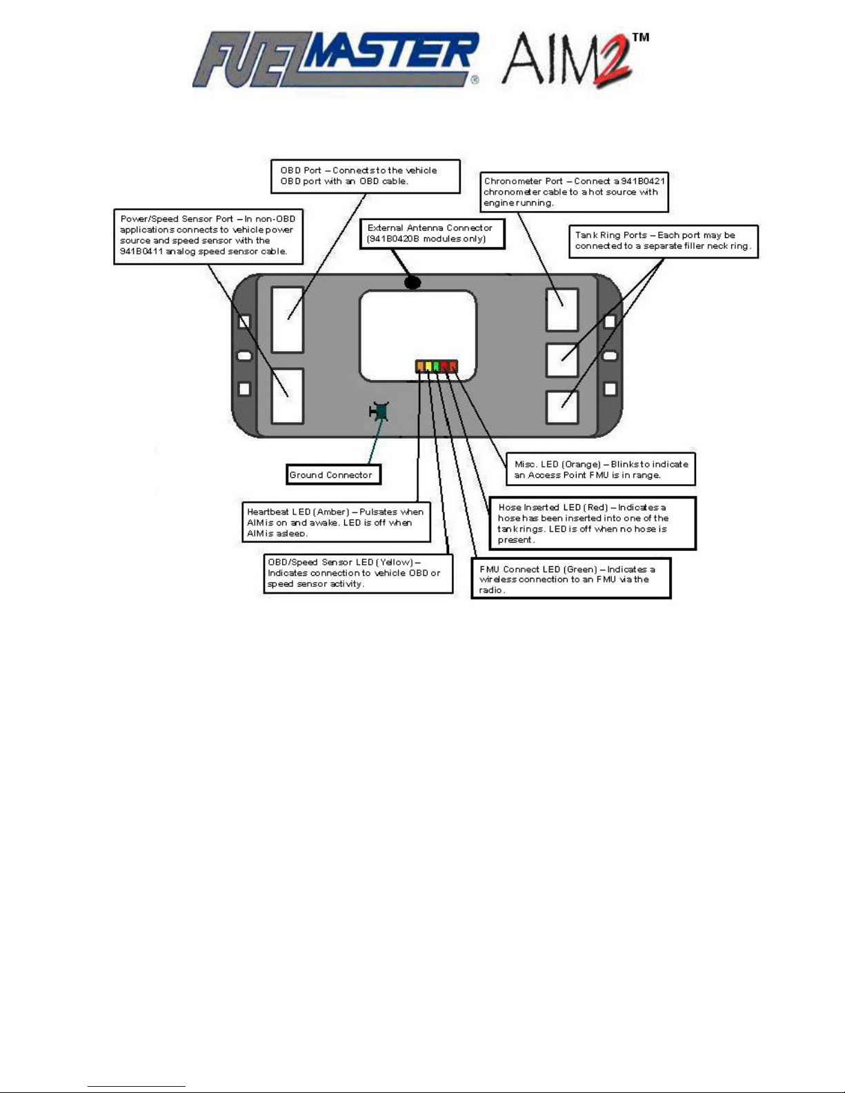
Figure 4-2. AIM2™ Module Layout
Using The OBD Port
• Do not install any AIM2™ components in close proximity to hot or moving vehicle parts.
• The AIM2™ module should be mounted out of harms way, but remain accessible for service and
troubleshooting.
1. Select a mounting location for the AIM2™ module. Recommended locations are under the dash
or under the seat on the same side of the vehicle as the fuel tank’s filler neck. Consider the
distance from the OBD Port to the mounting location. The OBD Diagnostic Pass-Thru cable must
connect between the AIM2™ module and the OBD connector. The cable is 48 inches long and
cannot be extended. Mount the AIM2™ module in the selected location.
Installations in Canada require the use of two 12 gauge wires to ground the AIM2™ module to a
chassis ground.
2. Using 12 AWG THHN wire, make a ground connection between the AIM2™ ground connector
and the vehicle/equipment chassis.
CAUTION
NOTE
33
Page 34

CAUTION
Protective wire loom should be used to enclose and protect cabling routed outside the vehicle
passenger compartment.
3. The RFID Extension Cable must be routed from the AIM2™ module outside the passenger
compartment to the RFID Interface Module near the fuel tank filler neck. If possible use an
existing wire chase opening to route the RFID Extension Cable outside the passenger
compartment. As required, drill a hole large enough for the connector on the RFID Extension
Cable to fit through.
4. Either end of the RFID Extension Cable may be connected to the AIM2™ module. Plug one end
of the cable into one of the module’s two Tank Ring Ports (Figure 4-2).
5. Route the other end of the RFID Extension Cable from the AIM2™ module to the fuel tank filler
neck. Use protective wire loom for any cable routed outside the passenger compartment, and
install grommets to seal any drilled holes. Leave room to adjust slack, and loosely attach the loom
and cable to the vehicle with cable ties.
6. Place the Filler Neck Ring around the filler neck under the fuel tank cap.
CAUTION
Use caution when working around the fuel tank filler neck with power tools. Some fuels are easily
ignitable, and some tools may generate sparks.
7. Route the Filler Neck Ring cable down the filler neck. As required, drill an access hole for the
Filler Neck Ring connector to pass through the housing at the top of the filler neck where the fuel
tank cap is located. If an access hole was drilled, protect the cable with a grommet.
8. Attach the RFID Interface Module to the Filler Neck Ring cable and the RFID Extension Cable
and secure in place with cable ties. If these connections are not in a protected space, use a
product similar to 3M Scotch Rubber Mastic Tape (product number 2228) or equivalent to cover
and protect all exposed connections.
9. From the AIM2™ module mounting location pull the slack from the RFID Extension Cable. Coil
any slack, and secure out of the way of the vehicle operator and/or moving parts.
10. As required, repeat steps 3 through 9 for the second tank of a dual tank installation.
11. Pull all cable ties tight and clip off the tag ends of the ties.
12. Seal any drilled holes/grommets with silicon sealant.
13. Connect the OBD interface cable to the vehicle OBD connector and AIM2™ module OBD port
(Fig. 4-2). Secure the cable out of the way of the vehicle operator and/or any moving parts.
14. Proceed to AIM2™ Post Installation Tests.
Using A Vehicle Speed Sensor (Odometer) Input Only
• Do not install any AIM2™ components in close proximity to hot or moving vehicle parts.
• The AIM2™ module should be mounted out of harms way, but remain accessible for service and
troubleshooting.
• The brown Analog Speed Sensor Cable wire must be connected to a source providing a 4 to
42VDC source wakeup signal to the AIM2™ module. This source must drop off to 2 VDC or less
to permit the module to go to sleep.
CAUTION
34
Page 35

1. Select a mounting location for the AIM2™ module. Recommended locations are under the dash
or under the seat on the same side of the vehicle as the fuel tank’s filler neck. The Analog Speed
Sensor Cable has five conductors: 1) RED (8 feet long) to +12 to +42 VDC fused and unswitched,
2) BLACK (2 feet long) to chassis ground, 3) GREEN (8 feet long) to positive odometer, 4)
WHITE (8 feet long) to negative odometer, and 5) BROWN (8 feet long) for wakeup/switched +4
to +42 VDC. Consider the distance from the AIM2™ Power/Speed Sensor Port to the required
connections when selecting a mounting location. Mount the AIM2™ module in the selected
location.
CAUTION
Some vehicles use more than one battery to increase system voltage, or
How the batteries are connected together will determine if the increase is in voltage or current. If the
same vehicle chassis ground to which the batteries are grounded is not used when wiring the ground
to the AIM2™ module, AIM2™ power will not match vehicle power and damage to the AIM2™
module and/or vehicle electrical system may occur. Always ground the AIM2™ module to the
same ground used by the batteries for the vehicle chassis ground.
NOTE
Installations in Canada require the use of two 12 gauge wires to ground the AIM2™ module to a
chassis ground.
2. Using 12 AWG THHN wire, make a ground connection between the AIM2™ ground connector
and the vehicle/equipment chassis.
CAUTION
To avoid possible damage to the AIM2™ module, do not connect the Analog Speed Sensor Cable to
the AIM2™ module until all other cable connections are complete.
NOTE
Important! Some applications may not function correctly unless the WHITE negative odometer wire
is connected directly to the negative side of the speed sensor.
3. Connect the Analog Speed Sensor Cable BLACK ground wire and WHITE negative odometer
wire to a chassis/battery ground.
CAUTION
If multiple batteries are in use in the vehicle being installed, take a voltage reading of the switched
and unswitched inputs of another existing vehicle accessory. Select power sources for AIM2™ which
have the same voltage inputs. Doing so may prevent damage to the AIM2™ module and/or the
vehicle electrical system.
4. Connect the Analog Speed Sensor RED wire to an unswitched (constant with ignition OFF) +12
to +42 VDC power supply.
5. Connect the Analog Speed Sensor BROWN wire to a switched (constant with ignition ON only)
+4 to +42 VDC power supply. This connection will “wakeup” the AIM2™ module when the ignition
switch is turned ON.
NOTE
On vehicles with Allison transmissions, DO NOT connect the Analog Speed Sensor Cable GREEN
wire to the transmission speed sensor. Connect the GREEN wire to the ECM speed sensing output.
available starting current.
6. Connect the Analog Speed Sensor Cable GREEN wire to the VSS (Vehicle Speed Sensor)
output. This signal may also be found at the vehicle’s computer module (ECM). Many speed
sensors have a two-wire connection. The output will be the wire with the higher resistance
reading.
7. The RFID Extension Cable must be routed from the AIM2™ module outside the passenger
compartment to the RFID Interface Module near the fuel tank filler neck. If possible use an
existing wire chase opening to route the RFID Extension Cable outside the passenger
35
Page 36

compartment. As required, drill a hole large enough for the connector on the RFID Extension
Cable to fit through.
8. Either end of the RFID Extension Cable may be connected to the AIM2™ module. Plug one end
of the cable into one of the module’s two Tank Ring Ports (Figure 4-2).
9. Route the other end of the RFID Extension Cable from the AIM2™ module to the fuel tank filler
neck. Use protective wire loom for any cable routed outside the passenger compartment, and
install grommets to seal any drilled holes. Leave room to adjust slack, and loosely attach the loom
and cable to the vehicle with cable ties.
10. Place the Filler Neck Ring around the filler neck under the fuel tank cap.
CAUTION
Use caution when working around the fuel tank filler neck with power tools. Some fuels are easily
ignitable, and some tools may generate sparks.
11. Route the Filler Neck Ring cable down the filler neck. As required, drill an access hole for the
Filler Neck Ring connector to pass through the housing at the top of the filler neck where the fuel
tank cap is located. If an access hole was drilled, protect the cable with a grommet.
12. Attach the RFID Interface Module between the Filler Neck Ring cable and the RFID Extension
Cable and secure in place with cable ties. If these connections are not in a protected space, use
a product similar to 3M Scotch Rubber Mastic Tape (product number 2228) or equivalent to cover
and protect all exposed connections.
13. From the AIM2™ module mounting location, pull the slack from the RFID Extension Cable. Coil
any slack, and secure out of the way of the vehicle operator and/or moving parts.
14. As required, repeat steps 7 through 13 for the second tank of a dual tank installation.
15. Pull all cable ties tight and clip off the tag ends of the ties.
16. Seal any drilled holes/grommets with silicon sealant.
17. Connect the Analog Speed Sensor Cable to the AIM2™ module Power/Speed Sensor Port (Fig.
4-2).
18. Proceed to AIM2™ Post Installation Tests.
Using An Analog Chronometer Input
Installations for analog chronometer input may be made with or without an OBD connection. When
made with an OBD connection, AIM2™ module power is derived through an OBD cable. When made
without an OBD connection an Analog Speed Sensor cable must be installed to connect to vehicle
power.
CAUTION
• Do not install any AIM2™ components in close proximity to hot or moving vehicle parts.
• The AIM2™ module should be mounted out of harms way, but remain accessible for service and
troubleshooting.
NOTE
• A chronometer need not be a physical device added to the vehicle/equipment to attain the
desired information. A chronometer input may be as simple as a power source which only is
powered under special circumstances. Engine runtime may be a power source which only
supplies power when the engine is running. PTO engage time may be a power source which only
supplies power when the PTO is engaged.
• The Analog Speed Sensor Cable and Analog Chronometer wires may be lengthened, as needed.
1. Select a mounting location for the AIM2™ module. Recommended locations are under the dash
or under the seat on the same side of the vehicle as the fuel tank’s filler neck. Consider the
distance to the required connections when selecting a mounting location. Mount the AIM2™
module in the selected location.
a. (With OBD) The OBD Diagnostic Pass-Thru Cable is 48 inches long and cannot be
extended. It must be connected between the AIM2™ module and the OBD connector. The
36
Page 37

Analog Chronometer Cable has two conductors eight feet long for connections to a maximum
of two analog chronometers.
b. (Analog Only) The Analog Speed Sensor Cable and Analog Chronometer Cable both must
be connected to the AIM2™ module. The Analog Speed Sensor Cable uses eight foot
conductors to connect to switched and unswitched power, and a two foot conductor to
connect to vehicle/battery ground. The Analog Chronometer Cable has two conductors eight
feet long for connections to a maximum of two analog chronometers.
CAUTION
Some vehicles use more than one battery to increase system voltage, or
How the batteries are connected together will determine if the increase is in voltage or current. If the
same vehicle chassis ground to which the batteries are grounded is not used when wiring the ground
to the AIM2™ module, AIM2™ power will not match vehicle power and damage to the AIM2™
module and/or vehicle electrical system may occur. Always ground the AIM2™ module to the
same ground used by the batteries for the vehicle chassis ground.
NOTE
Installations in Canada require the use of two 12 gauge wires to ground the AIM2™ module to a
chassis ground.
2. Using 12 AWG THHN wire, make a ground connection between the AIM2™ ground connector
and the vehicle/equipment chassis.
CAUTION
To avoid possible damage to the AIM2™ module, do not connect the Analog Speed Sensor Cable to
the AIM2™ module until all other cable connections are complete.
NOTE
Some applications may not function correctly unless the WHITE negative odometer wire is connected
directly to the negative side of the speed sensor.
3. (Analog Only) Connect the Analog Speed Sensor Cable BLACK ground wire and WHITE
negative odometer wire to a chassis/battery ground.
CAUTION
If multiple batteries are in use in the vehicle being installed, take a voltage reading of the switched
and unswitched inputs of another existing vehicle accessory. Select power sources for AIM2™ which
have the same voltage inputs. Doing so may prevent damage to the AIM2™ module and/or the
vehicle electrical system.
4. (Analog Only) Connect the Analog Speed Sensor RED wire to an unswitched (constant with
ignition OFF) +12 to +42 VDC power supply.
5. (Analog Only) Connect the Analog Speed Sensor BROWN wire to a switched (constant with
ignition ON only) +4 to +42 VDC power source. This connection will “wakeup” the AIM2™ module
when the ignition switch is turned ON. This power source must drop to 2 VDC or less when
switched off for the module to go to sleep.
NOTE
• Step 6 calls out connections to obtain engine run time and power takeoff (PTO) engage time.
These connections may be used to obtain any combination of either operation such as engine run
time from both the parent truck engine and a reefer engine.
• Either channel (1=orange or 2=blue) may be used for any analog chronometer connection.
Ensure the application is tracked so the software may be configured to match. In the vehicle
record in the software, the channel number and application must be selected for each configured
chronometer. Be sure to check Analog in the vehicle record when using the Analog Chronometer
Cable.
available starting current.
37
Page 38

6. Determine the desired application(s). For engine run time a connection must be made to a source
providing power only
connection must be made to a source providing power only
the Analog Chronometer Cable channel 1 ORANGE wire to the first choice. If needed, connect
the channel 2 BLUE wire to the second choice. Note the channel and connection type for
software configuration.
7. The RFID Extension Cable must be routed from the AIM2™ module outside the passenger
compartment to the RFID Interface Module near the fuel tank filler neck. If possible use an
existing wire chase opening to route the RFID Extension Cable outside the passenger
compartment. As required, drill a hole large enough for the connector on the RFID Extension
Cable to fit through.
8. Either end of the RFID Extension Cable may be connected to the AIM2™ module. Plug one end
of the cable into one of the module’s two Tank Ring Ports (Fig. 4-2).
9. Route the other end of the RFID Extension Cable from the AIM2™ module to the fuel tank filler
neck. Use protective wire loom for any cable routed outside the passenger compartment, and
install grommets to seal any drilled holes. Leave room to adjust slack, and loosely attach the loom
and cable to the vehicle with cable ties.
10. Place the Filler Neck Ring around the filler neck under the fuel tank cap.
Use caution when working around the fuel tank filler neck with power tools. Some fuels are easily
ignitable, and some tools may generate sparks.
11. Route the Filler Neck Ring cable down the filler neck. As required, drill an access hole for the
Filler Neck Ring connector to pass through the housing at the top of the filler neck where the fuel
tank cap is located. If an access hole was drilled, protect the cable with a grommet.
12. Attach the RFID Interface Module between the Filler Neck Ring cable and the RFID Extension
Cable and secure in place with cable ties. If these connections are not in a protected space, use
a product similar to 3M Scotch Rubber Mastic Tape (product number 2228) or equivalent to cover
and protect all exposed connections.
13. From the AIM2™ module mounting location pull the slack from the RFID Extension Cable. Coil
any slack, and secure out of the way of the vehicle operator and/or moving parts.
14. As required, repeat steps 7 through 13 for the second tank of a dual tank installation.
15. Pull all cable ties tight and clip off the tag ends of the ties.
16. Seal any drilled holes/grommets with silicon sealant.
17. (Analog) Connect the Analog Speed Sensor Cable to the AIM2™ module Power/Speed Sensor
Port (Fig. 4-2).
18. (With OBD) Connect the OBD interface cable to the vehicle OBD connector and AIM2™ module
OBD Port (Fig. 4-2). Secure the cable out of the way of the vehicle operator and/or any moving
parts.
19. Proceed to AIM2™ Post Installation Tests.
when the engine is running. For power takeoff (PTO) engage time, a
when the PTO is engaged. Connect
CAUTION
38
Page 39

AIM2™ Post Installation Tests
Following successful installation of the AIM2™ vehicle equipment, the module must be programmed
with information sent from the Central Controller. The information is sent to an FMU-3500, then from
the FMU to the AIM2™ module. The AIM2™ module cannot be programmed if it 1) does not have a
heartbeat, 2) does not recognize the OBD/power connection, 3) does not recognize a nozzle tag
insertion into a filler neck ring, and 4) does not recognize an FMU-3500. All these conditions must be
met before the AIM2™ module may be programmed.
A Programming Hose Tag (PHT) is shipped with each new AIM2™ system. The PHT may be used to
test a nozzle tag insertion into a filler neck ring.
An FMU-3500 is required to complete the AIM2™ post installation tests. An FMU-3500 Programmer
is necessary to program installed AIM2™ modules. A portable FMU-3500 Programmer may be
developed to test and program at a location remote from the fuel island FMU-3500 (at the AIM2™
installation location). See Develop an FMU-3500 Programmer (Section 5) for instructions to prepare
a Programmer. The instructions include development of a portable FMU-3500 Programmer.
Perform the following:
1. (OBD) Turn the vehicle ignition switch on. The amber Heartbeat LED should start pulsing, and
the yellow OBD/Speed Sensor LED should illuminate.
2. (Analog) Drive the vehicle. The yellow OBD/Speed Sensor LED should illuminate.
3. Position a PHT over the filler neck ring. Check the red Hose Inserted LED illuminates.
4. Remove the PHT. Check the red Hose Inserted LED goes out.
NOTE
The green FMU Connect LED will illuminate solid green when the AIM2™ module connects to an
FMU-3500. The green FMU Connect LED may blink when the AIM2™ module detects an FMU3500 but has not connected to it. In AIM2™ firmware revisions 1.18 through 1.21, a nozzle tag must
be inserted into the filler neck ring for the AIM2™ module to connect to the FMU-3500. AIM2™
firmware revisions 1.22 and above do not require a nozzle tag to be inserted into the filler neck ring
to connect to an FMU-3500. The AIM2 connects as soon as the vehicle stops. Connection will also
occur if a nozzle tag is inserted into the filler neck ring.
5. Move the vehicle within RF range of an FMU-3500 or FMU-3500 Programmer. If using AIM2™
firmware revision 1.18 through 1.21, position a nozzle tag over the filler neck ring. The green
FMU Connect LED should illuminate. If the green LED is blinking, the AIM2™ sees the FMU but
cannot connect.
6. When all LEDs can illuminate, the AIM2™ module is ready to be programmed. Proceed to
AIM2™ Programming (Section 5).
39
Page 40

40
Page 41

SECTION 5
AIM2™ PROGRAMMING
Develop an FMU-3500 Programmer
An FMU-3500 Programmer is needed to program the AIM2™ module before it is placed in use, and
may also be used to perform AIM2™ post installation tests. For small quantity installations, the
AIM2™ equipment may be tested and programmed using the FMU-3500 installed at the fuel island.
For larger numbers of installations in a garage or someplace remote from the fuel island, a portable
programmer may be developed and carried to the installation site for testing and programming. A
portable Programmer may be developed by removing the upper cabinet from a fuel island FMU-3500,
or it may be developed from a demonstration unit provided by a FuelMaster® distributor. After testing
and programming is complete, the Programmer may be restored to its original configuration as a fully
configured FMU-3500 or demonstration unit.
A portable Programmer must be configured with the same upper cabinet components as the fuel
island FMU-3500. It must have a compact flash card, an FMU radio board (FRB), antennas, matching
site signature and system type, and a means to receive uploads from the Central Controller.
Configure an FMU-3500 as an FMU-3500 Programmer:
1. Through a laptop connection:
a. Verify the FMU is a master FMU configured as an FMU-3500 with AIM2™ antennas, an
FMU Radio Board, and a compact flash card, and communications with a laptop or Central
Controller has been established.
NOTE
The FuelMaster
to configure an FMU-3500 as an FMU-3500 Programmer in accordance with 3. Through the
Central Controller, below.
b. Establish a laptop connection in accordance with the guidance provided in Product Bulletin
111.
c. At the SITE> prompt, input command 73. The following will be displayed:
AIM2 Configure Programming Unit Status
--------------------------------------
73, ARG1, ARG2
ARG1 – Operation
= 0, Is command supported?
= 1, Is this an AIM programming unit?
= 2, Disable FMU as AIM programming unit.
= 3, Enable FMU as AIM programming unit.
= 4, Set programming hose tag.
= 5, Display current programming hose tag.
ARG2 – Hose Tag Number (use with ARG1 = 4)
d. Input 73,3 and press Enter. The following will be displayed:
FMU programming status set to YES
or
FMU programming status was already YES
software may also be loaded on a laptop, and a direct connect cable may be used
®
41
Page 42

e. As desired, input 73,1 to confirm. The following will be displayed:
SITE>73,1
YES
SITE>
f. YES confirms the FMU is configured as a Programmer.
g. Disconnect in accordance with Product Bulletin 111.
2. Through the Central Controller:
a. Verify the FMU is a master FMU configured as an FMU-3500 with AIM2™ antennas, an
FMU Radio Board, and a compact flash card, and communications with a laptop or Central
Controller has been established.
NOTE
The FuelMaster
software may reflect the selected FMU-3500 is an AIM2™ Programmer, but it
®
cannot be verified until the configuration change has been uploaded to the FMU. To ensure the FMU
is configured as an AIM2™ Programmer, the configuration should be changed as shown below and
uploaded to the FMU.
b. Access the FuelMaster
software main window.
®
c. Click on the Config icon. A Configuration window will open.
d. Click on the System tab. The System window will be displayed.
e. In the lower right corner of the window, verify the Passive Sys Type is AIM2 (AIM2 may be
grayed out, but still visible as AIM2). Click OK to save and exit this window.
f. Click on the Site icon. A dropdown Site List menu will open.
g. In the site listing shown, click on to highlight the site to be configured as a Programmer.
h. Once highlighted, click on Open to open the desired site window. A Site ID XXXX window
will open.
i. In the lower right corner of the window, change the FMU: description to FMU 2500 Plus AIM
II Prog. Click on Apply to save the change.
j. In the lower left under the FMU(s) tab, click the Online button. The Configuration
Upload/Do… window will open.
k. Under Selected FMUs, click in the box to the left of the FMU selected to be a Programmer.
A checkmark (√) will appear in the box, and the U
l. Click on the U
pload button. A Status Output Window will open and display the upload
pload and Download buttons will open.
progress.
m. When a connection to the selected FMU is established, the new configuration will be
uploaded and the FMU will be converted to a Programmer. When the upload is complete,
the Central Controller will disconnect from the FMU.
n. Close all open windows and exit the FuelMaster
software program. The selected FMU-
®
3500 is an AIM2™ Programmer.
Develop a portable FMU-3500 Programmer from a fully configured FMU-3500:
1. Perform “Convert an FMU-3500 into an FMU-3500 Programmer” to ensure the FMU has
been converted to a Programmer.
2. Remove the FMU-3500 upper cabinet from the FMU-3500 pedestal:
a. Unlock and open the FMU pedestal access door, and turn off the FMU power switch.
b. Unlock and open the FMU upper cabinet door.
c. Disconnect all cables, as required, which extend from the pedestal and connect to the upper
cabinet. Check for the power cable and communications cable connections to the cable
interface plate in the bottom of the upper cabinet, a possible network cable connection to the
NIC card, and any cables routed through the bulkhead thru-hole to the Satellite I/O Control
Board.
d. Support the upper cabinet and remove the six screws securing the upper cabinet to the
pedestal.
e. Remove the upper cabinet.
3. Separate the AC power connection (black, green, white wires) at the base of the upper cabinet.
42
Page 43

4. Fabricate a power connection to the upper cabinet. A power cable may be fabricated from
components available through Tyco Electronics, and an AC power cord with 18AWG conductors
and a male connector. Select an AC power cord with sufficient length to reach from a wall outlet
to the Programmer. Ensure one end of the power cable has exposed black, white, and green
wires.
a. Strip approximately ¼ inch of insulation from the exposed ends of the black, white, and
green wires.
b. Obtain one Tyco Electronics 1-480305-0 connector housing, and three Tyco Electronics
60618-4 contacts.
c. Crimp the three contacts onto the exposed ends of the black, white, and green wires.
d. The connector housing has pin receptacles numbered 1, 2, and 3. The contacts crimped
onto the ends of the black, white, and green wires have keepers that hold the pins in the
connector housing. Push the contact on the white wire into the receptacle numbered “1” until
it bottoms in the housing. The keeper should retain the pin in the housing. Repeat with the
contact on the green wire into the “2” receptacle, and the contact on the black wire into the
“3” receptacle. When finished you should have a power cable with a male plug at one end,
and the connector housing at the other end.
5. Position the Programmer out of the way but within line of sight of the vehicles being fitted with
AIM2™.
6. Plug the connector housing end of the power cable into the female power receptacle of the FMU
upper cabinet. The connectors should be keyed so they will only connect one way. After
connection, verify the wires at both sides of the connectors match white to white, green to green,
and black to black.
7. Plug the power cable into a 115 VAC power outlet. After a brief power-up delay and initialization,
the FMU Programmer should display:
**FuelMaster FUELS ACCOUNTING SYSTEM**
** INSERT KEY OR CARD TO BEGIN **
8. Recommend the circuit breaker for the FMU pedestal be turned off, and a lockout/tagout tag
installed to let people know it should not be turned on.
9. Cover the opening at the top of the FMU pedestal to prevent rain/snow/debris from entering the
exposed pedestal.
Develop an FMU-3500 Programmer from an FMU-3500 demonstration unit: an
FMU-3500 demonstration unit may have all the hardware components to meet the task, but it may
not have the correct site signature and system type, nor may it be set to be a Programmer.
1. Set the correct site signature, system type, and Programmer option:
a. Determine the site signature and system type necessary to change the demonstration unit.
b. Plug the demonstrator unit into a 115 VAC power outlet. After a brief power-up delay and
initialization, the unit should display:
**FuelMaster FUELS ACCOUNTING SYSTEM**
** INSERT KEY OR CARD TO BEGIN **
c. A laptop connection to the demonstrator unit will be necessary to change the site signature
and system type, as required. Make the laptop connection in accordance with Product
Bulletin 111.
d. Use command 38 to change the site signature:
1) When the 38 command is sent to the FMU, the following display appears:
Entering Configuration Mode!
CURRENT SIGNATURE = 1234
NEW SIGNATURE (XXXX hex –or- #99999 dec) = ___
2) 1234 is an example. Enter the new site signature at the flashing cursor:
43
Page 44

CURRENT SIGNATURE = 1234
NEW SIGNATURE (XXXX hex –or- #99999 dec) = 4321
SITE SIGNATURE SET TO: 4321
SAVING SYSTEM CONFIGURATION…
CONFIGURATION RECORDED.
2. Use command 59 to change the system type, as required:
a. When the 59 command is sent to the FMU, the following display appears:
CURRENT SYSTEM OPTIONS (MENU 1) CONFIGURATION
-------------------------------------------- A. SYSTEM INPUT TYPE : VMN - VEH. KEY
B. CUSTOM SYSTEM OPTION : DISABLED
C. ENTERED VEHICLE IDs ARE : NUMERIC
D. SEMI MANUAL MODE : DISABLED
E. REAL GATE TXN : DISABLED
F. POWER FAIL CHECK : NOT AVLAILABLE
G. ENTERED USER IDs ARE : NUMERIC
H. FURNACE LOGGING : DISABLED
I. USING OLD PROKEES : DISABLED
J. SHOW PROKEE/SMARTCARD ID : DISABLED
K. CONFIRM PROKEE/SMARTCARD ID : DISABLED
L. DISPLAY PUMP PRICING : DISABLED
M. EIU PROKEE/SMARTCARD WHICH KEYS : VEH & USER KEY
N. TWO RELAYS PER PUMP : DISABLED
O. AUTO ACTIVATE SINGLE PUMP : DISABLED
P. MODEM CONNECT UPPER SPEED LIMIT : MAXIMUM
USAGE - <LETTER>=CHANGE VALUE, <ESC>=EXIT
b. Option A shows the system type. If the system type is not correct, depress A until the correct
system type appears.
c. When the correct system type is displayed, press Esc. The new system type will be
recorded and the following will be displayed:
CONFIGURATION HAS CHANGED!
WOULD YOU LIKE TO SAVE IT ? (Y/N)
d. If the new system type is correct, depress Y to save it. The following will be displayed:
SAVING SYSTEM CONFIGURATION…
CONFIGURATION RECORDED.
3. Perform “Convert an FMU-3500 into an FMU-3500 Programmer” to configure the FMU
demonstrator unit as a Programmer.
Create an AIM2™ Programmer Prokee®/Smartcard
AIM2™ programming through an FMU-3500 is initiated using either a Supervisor
Prokee
Prokee
used to authorize fuel transactions, or to reconfigure an FMU, or most other taskings a
Supervisor Prokee
assigned to individuals identified in the AIM2 Programmer List.
Create an AIM2™ Programmer Prokee®/Smartcard:
/Smartcard, or an AIM2™ Programmer Prokee®/Smartcard. An AIM2™ Programmer
®
/Smartcard may not be used for functions other than programming AIM2™. It cannot be
®
/Smartcard can accomplish. AIM2™ Programmer Prokee/Smartcards are
®
44
Page 45

1. Access the FuelMaster® software main window.
NOTE
If AIM2 Programmer in the following step is not available, or grayed out, there is no Central
Controller operator authorized to make an AIM2™ Programmer Prokee
/Smartcard.
®
2. Click on Tables from the menu bar. If AIM2 Programmer is not available or grayed out,
proceed to step 3. If AIM2 Programmer is available, proceed to step 10.
3. Click on the Config icon. A Configuration window will open.
4. Click on the System tab. The System window will appear.
5. In the lower right corner of the System window, change the Passive Sys Type to AIM2.
6. In the right margin, click on O
K. The System window will close.
7. Click on the Exit icon to exit the software program.
8. Re-enter the FuelMaster
software main window.
®
9. Click on Tables from the menu bar. AIM2 Programmer… should now be listed in the
dropdown menu, but may be grayed out.
10. From the menu bar, click on System. A dropdown menu will appear.
11. From the dropdown menu, click on O
perator Options and select List Maintenance…. An
Operator List window will open.
12. Highlight the operator who will be making the AIM2™ Programmer Prokee
/Smartcard, then
®
click on the Open button at the bottom of the window. An Operator Name: XXX window will
open
13. Select the options this operator should have by clicking on the box to the left of each option.
All options may be selected or deselected by clicking on the appropriate Select All or
Deselect All button in the bottom left corner of the window.
14. Click OK at the bottom of the window to save and close the window. There is now a Central
Controller operator authorized to make AIM2™ Programmer Prokee
/Smartcards.
®
15. Click on Tables from the menu bar. AIM2 Programmer… should now be listed in the
dropdown menu and should not be grayed out.
16. Click on AIM2 Programmer… An AIM2 Programmer List window will open. This window
identifies individuals who have been selected to receive an AIM2™ Programmer
Prokee
/Smartcard. The Encoded column indicates if the Programmer Prokee® has already
®
been encoded.
17. Click on A
dd in the right margin to add a programmer. An AIM2 Programmer ID [NEW]
window opens.
18. Enter an AIM2 Prog. ID in the space provided. Up to 8 characters may be used. If fewer than
8 characters are entered zeros will be entered to the left to complete 8 characters. After the
AIM2 Prog. ID is entered, the window title will change to reflect the new ID.
19. Complete as much additional information in this window as desired. A name should be
entered as a minimum.
20. Click on the PROKEE tab if it is desired for this programmer to use a PIN, then in the
PROKEE window click on the box next to PIN.
21. Ensure the Encoder is connected and a Prokee
22. Click on E
ncode in the right margin. A Prokee window will open and prompt Insert Prokee
/Smartcard is available.
®
into Encoder for Writing.
23. Push a Prokee
(or insert a Smartcard) into the Encoder for encoding. When encoding is
®
complete, the Prokee window will prompt Prokee Encoded Successfully!
24. The AIM2™ Programmer Prokee/Smartcard is encoded. Click on the OK button to close the
Prokee window.
25. Click on O
K in the right margin to close the AIM2 Programmer ID window. The new
programmer ID and name should be listed in the AIM2 Programmer List with Encoded
marked YES.
26. Close any open windows and exit the software program.
45
Page 46
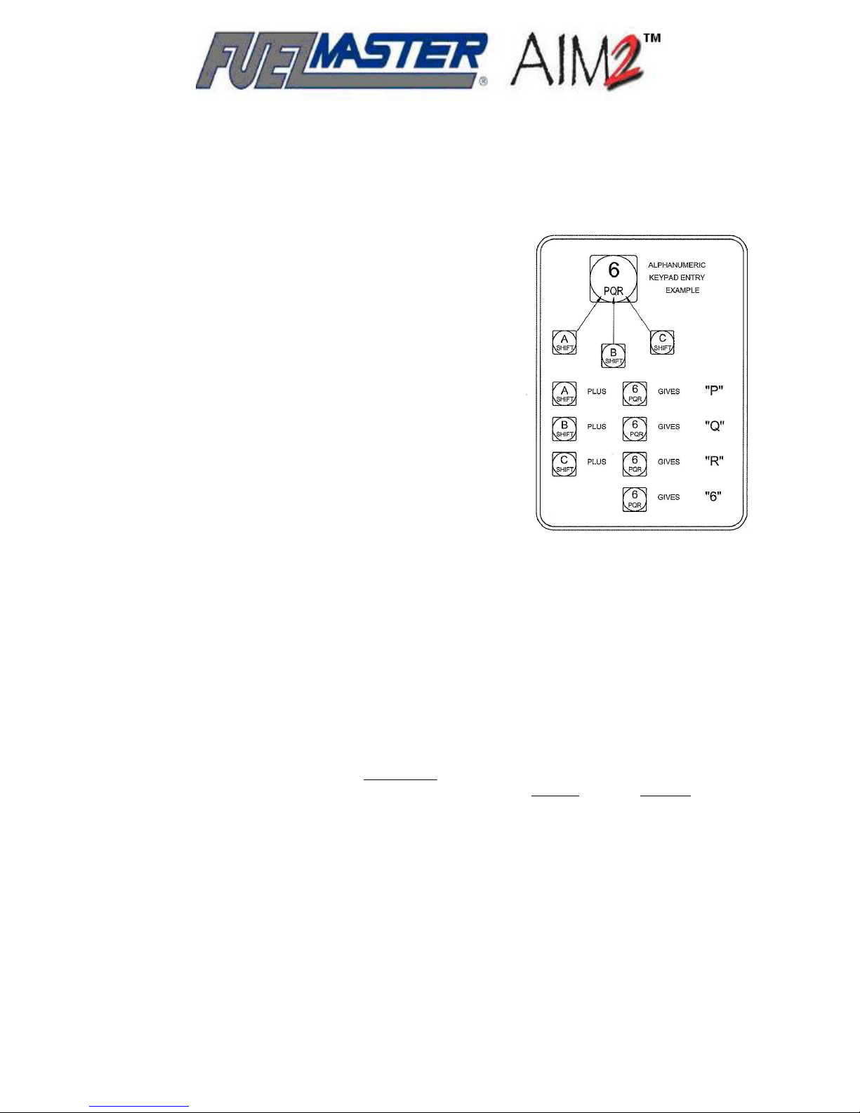
Programming the AIM2™ Module
Programming AIM2™ modules may only be performed through an FMU-3500 configured as an
AIM2™ Programmer. The AIM2™ Programmer may be a fuel island FMU configured as a
programmer, or a portable programmer configured from an FMU upper cabinet or an FMU
demonstration unit. Additionally, only vehicle records marked a
may be used to program an AIM2™.
ome prompts may ask to depress a key not found on a 4x4
S
keypad (keypad with 16 keys). If that is the case, follow the
instructions shown in Figure 11 to shift to attain the desired
key.
Program an AIM2™:
1. At the Central Controller, ensure vehicle records in
the FuelMaster
AIM2™ with AIM Program Pending.
2. From the Central Controller, Send Au
to the AIM2™ Programmer.
3. As required, set PHT in FMU:
a. Insert a Supervisor Pro
following will be displayed:
software program are marked for
®
thorization List
kee /Smartcard. The
®
* SUPV: 1=SYSTEM, 2=PM, 3=ODOM, 4=AIM *
* A=CONFIG, B=ISSUES, C=TANKS, D=EXIT *
b. Depress 4=AIM. The following will be displayed:
AIM SUPERVISOR MENU
T, D=EXIT
1=SET PHT, 2=PROGRAM, 3=RESE
c. Depress 1=PHT. The following will be displayed:
AIM SUPERVISOR MENU
Curr :__
ent PHT A: New PHT (A-F)
NOTE
Very Important! The PHT letter entered must m
and, if multiple Programmers are within RF range of each other, they must all
atch the letter assigned to the Programming Hose Tag
d. Depress the key to set the desired PHT letter (i.e., B) at the cursor, then depress the
Enter key. The following will be displayed:
AIM SUPERVISOR MENU
Curr ): B
ent PHT A: New PHT (A-F
changing to:
AIM SU MENU
PERVISOR
Programming Hose Tag Changed to B
e. Exit the FMU Supervisor menu.
s AIM2™ with AIM Program Pending
Figure 5-1. 4x4
Keypad Shift
Instructions
be using different PHT’s.
46
Page 47

NOTE
AIM2™ programming may be initiated with a Supervisor Prokee
Programmer Prokee
Prokee
the display shown in step 6.
/Smartcard. Procedures when using an AIM2™ Programmer Prokee®/Smartcard begin with
®
/Smartcard. The following instructions begin using a Supervisor
®
/Smartcard or an AIM2™
®
4. Insert a Supervisor Prokee®/Smartcard. The following will be displayed:
* SUPV: 1=SYSTEM, 2=PM, 3=ODOM, 4=AIM *
* A=CONFIG, B=ISSUES, C=TANKS, D=EXIT *
5. Depress 4=AIM. The following will be displayed:
NOTE
Some older versions of FMU firmware may show RESET instead of CLEAN in the following
display.
AIM SUPERVISOR MENU
1=SET PHT, 2=PROGRAM, 3=CLEAN, D=EXIT
6. Depress 2=PROGRAM. The FMU will search for an AIM2™ to program, but will not find the
AIM2™ until a PHT is placed on the vehicle filler neck ring:
NOTE
If an AIM2™ Programmer Prokee
observed.
/Smartcard is being used, the following is the first display to be
®
***** SEARCHING FOR AIM TO PROGRAM *****
* Insert Programming Hose Tag *
NOTE
If an AIM2™ is not found, it may be because the module was previously cleaned and the interface is
set to NONE. If this occurs, remove the PHT, turn the vehicle ignition switch on for 20 seconds then
turn the ignition switch off and repeat step 4. The interface should be set and the module should be
detected when the PHT is placed on the filler neck ring.
7. Position the PHT on the tank ring of the vehicle being programmed. The FMU briefly displays
the AIM2™ has been found, then prompts to insert the vehicle ID (VID):
***** Found AIM To Program *****
COMMUNICATING WITH AIM…
changing to:
VID: UNKNOWN (PHT A)
ENTER VEHICLE ID -> ________
8. Enter the VID and press Enter. The FMU briefly displays it is programming the AIM2™.
Notification is given when programming is complete, then the display changes to the Main
Menu (see following NOTE if display prompts No Record Found):
VID: 1001555 (PHT A)
PROGRAMMING AIM…
changing to:
VID: 1001555 (PHT A)
47
Page 48

******AIM PROGRAMMING COMPLETE*******
changing to:
NOTE
Some older versions of FMU firmware may show RESET instead of CLEAN in the following
display.
VID: 1001555 [-MAIN MENU-] (PHT A)
1=CALIBRATE 2=INTERFACE 3=CLEAN D=EXIT
NOTE
The message No Record Found indicates no AIM2™ vehicle record has been found for the VID
entered. Ensure the correct vehicle ID was entered, and the AIM2™ vehicle record has been sent to
the FMU. In the Central Controller, the vehicle record should display AIM Program Pending. If an
error was found, respond to the following question by depressing the Yes key, and try again.
VID: 1001555 (PHT A)
NO RECORD FOUND. TRY AGAIN (Y/N)?
9. Depress D=EXIT until the FMU returns to the default display. Insert an AIM2™ Installation
Notice in the vehicle to inform users of the AIM2™ installation. If calibration, change
interface, or clean is desired, continue to one of the following actions.
Calibrate AIM2™: calibration may be used to recalibrate odometer or chronometer settings, a
useful option when transferring AIM2™ modules to a new vehicle. Odometer will appear under the
CALIBRATE choices, regardless of OBD or analog interface, or regardless of any chronometer
selection. If no chronometers were selected when building the vehicle record, odometer recalibration
will be the only option. If chronometers were selected when building the vehicle record, the recalibrate
options will include odometer plus the selected chronometers. Access to the [-MAIN MENU-] is only
possible by first reprogramming the AIM2™ module.
NOTE
AIM2™ programming may be initiated with a Supervisor Prokee®/Smartcard or an AIM2™
Programmer Prokee®/Smartcard. The following instructions begin using a Supervisor
Prokee®/Smartcard. Procedures when using an AIM2™ Programmer Prokee®/Smartcard begin with
the display shown in step 3.
1. Insert a Supervisor Prokee®/Smartcard. The following will be displayed:
* SUPV: 1=SYSTEM, 2=PM, 3=ODOM, 4=AIM *
* A=CONFIG, B=ISSUES, C=TANKS, D=EXIT *
2. Depress 4=AIM. The following will be displayed:
NOTE
Some older versions of FMU firmware may show RESET instead of CLEAN in the following
display.
AIM SUPERVISOR MENU
1=SET PHT, 2=PROGRAM, 3=CLEAN, D=EXIT
48
Page 49

3. Depress 2=PROGRAM. The FMU will search for an AIM2™ to program, but will not find the
AIM2™ until a PHT is placed on the vehicle filler neck ring:
NOTE
If an AIM2™ Programmer Prokee
observed.
/Smartcard is being used, the following is the first display to be
®
***** SEARCHING FOR AIM TO PROGRAM *****
* Insert Programming Hose Tag *
NOTE
If an AIM2™ is not found, it may be because the module was previously cleaned and the interface is
set to NONE. If this occurs, remove the PHT, turn the vehicle ignition switch on for 20 seconds then
turn the ignition switch off and repeat step 4. The interface should be set and the module should be
detected when the PHT is placed on the filler neck ring.
4. Position the PHT on the tank ring of the vehicle being programmed. The FMU briefly displays
the AIM2™ has been found, then prompts to confirm the found vehicle ID (VID):
***** Found AIM To Program *****
COMMUNICATING WITH AIM…
changing to:
VID: 1001555 (PHT A)
IS THIS CORRECT (Y/N)?
NOTE
If the VID is not correct, press the No key and be prompted to enter the correct VID.
5. Depress the Yes key. The FMU briefly displays it is programming the AIM2™. Notification is
given when programming is complete, then the display changes to the Main Menu:
VID: 1001555 (PHT A)
PROGRAMMING AIM…
changing to:
VID: 1001555 (PHT A)
******AIM PROGRAMMING COMPLETE*******
changing to:
VID: 1001555 [-MAIN MENU-] (PHT A)
1=CALIBRATE 2=INTERFACE 3=RESET D=EXIT
6. To calibrate the AIM2™ module, depress 1=CALIBRATE. The CALIBRATE menu is
displayed:
NOTE
If PTO was one of the chronometer choices made when building the vehicle record, it will be
shown in the following display as one of the calibrate options.
VID: 1001555 [-CALIBRATE-] (PHT A)
1=ODOMETER 2=RUN TIME 3=IDLETIME D=EXIT
NOTE
• Steps 7 thru 9 are for recalibrating odometer with an OBD connection. For analog speed
sensor connections a prompt will appear to input an initial odometer reading, then the vehicle
49
Page 50

must be driven at least 5 miles (a greater distance is recommended for accuracy) and a
second odometer reading is entered. AIM2™ will then use this information to calibrate analog
speed sensor odometer readings.
• Two odometer entries are required to calibrate the odometer. If no odometer entry is shown
in step 7, the steps performed to input an odometer entry must be repeated after driving the
vehicle to obtain a second odometer entry. See step 8.
7. Depress 1=ODOMETER to calibrate the odometer. A prompt will be displayed to confirm
recalibration of the odometer:
VID: 1001555 ODOM: 0000129 (PHT A)
RECALIBRATE ODOMETER (Y/N)?
NOTE
If the following message appears, the FMU cannot detect the odometer reading. Exit the FMU,
run the vehicle engine for one or two minutes, and try again.
* VEHICLE NOT READY. TURN VEHICLE KEY *
* ON. WAIT 20 SECONDS, AND TRY AGAIN. *
8. Depress the Yes key to recalibrate the odometer. A prompt will appear for the input of the
CURRENT ODOMETER (MILES):
VID: 1001555 ODOM: 0000129 (PHT A)
CURRENT ODOMETER (MILES) -> _______.__
9. Enter the current odometer reading and press Enter. If a previous odometer entry had been
entered, AIM2™ will recalibrate based on the new odometer entry:
VID: 1001555 ODOM: 0000129 (PHT A)
CURRENT ODOMETER (MILES) -> 1111_.__
changing to:
VID: 1001555 ODOM: 0001111 (PHT A)
*** ODOMETER RECALIBRATION COMPLETE ***
changing to:
NOTE
Some older versions of FMU firmware may show RESET instead of CLEAN in the following
display.
VID: 1001555 [-MAIN MENU-] (PHT A)
1=CALIBRATE 2=INTERFACE 3=CLEAN D=EXIT
10. If a previous odometer entry was not displayed in step 7, drive the vehicle at least 5 miles
and repeat steps 6 through 9 to accurately calibrate odometer.
11. To recalibrate a chronometer, depress 1=CALIBRATE. The CALIBRATE menu is displayed:
NOTE
• In the following display, the chronometers listed will be those selected for the AIM2™ when
the vehicle record was developed with the software. The choices may be run time, idle time,
and/or PTO time. The recalibration procedure is the same for all chronometer options.
Version 5 software may offer the selection of up to 3 chronometers. The following display
may reflect as many as 3 chronometers in addition to odometer. Select the chronometer to
recalibrate.
50
Page 51

• If a specific chronometer value is not known when calibrating, enter 0 (zero) for the
chronometer value and continue.
VID: 1001555 [-CALIBRATE-] (PHT A)
1=ODOMETER 2=RUN TIME 3=IDLETIME D=EXIT
12. Depress 2=RUN TIME to calibrate engine run time. A prompt will be displayed to confirm
recalibration of engine run time:
VID: 1001555 RUN TIME: 000000 (PHT A)
RECALIBRATE RUN TIME (Y/N)?
13. Depress the Yes key to recalibrate engine run time. A prompt will appear for the input of the
current vehicle hour meter:
VID: 1001555 RUN TIME: 000000 (PHT A)
CURRENT RUN TIME -> ________
NOTE
In step 13, if the current engine run time is not available, enter zero.
14. Enter the current engine run time and press Enter. AIM2™ will recalibrate based on the new
engine run time entry:
VID: 1001555 RUN TIME: 000000 (PHT A)
CURRENT RUN TIME -> 222___
changing to:
VID: 1001555 RUN TIME: 000222 (PHT A)
*** RUN TIME RECALIBRATION COMPLETE ***
NOTE
Some older versions of FMU firmware may show RESET instead of CLEAN in the following
display.
VID: 1001555 [-MAIN MENU-] (PHT A)
1=CALIBRATE 2=INTERFACE 3=CLEAN D=EXIT
15. As required, depress D=EXIT to exit the FMU.
Change the AIM2™ Interface: interface options are NONE, OBD, and SPEED SENSOR.
When an AIM2™ is “cleaned”, the interface is set to NONE. The module cannot be programmed
when the interface is NONE. Modules should detect the correct interface when installed in a vehicle
and powered through the ignition switch. If it is necessary to change the interface through the FMU,
perform the following (access to the MAIN MENU is only possible by first reprogramming the AIM2™
module):
NOTE
AIM2™ programming may be initiated with a Supervisor Prokee
Programmer Prokee
Prokee
the display shown in step 3.
/Smartcard. Procedures when using an AIM2™ Programmer Prokee®/Smartcard begin with
®
/Smartcard. The following instructions begin using a Supervisor
®
1. Insert a Supervisor Prokee®/Smartcard. The following will be displayed:
51
/Smartcard or an AIM2™
®
Page 52

* SUPV: 1=SYSTEM, 2=PM, 3=ODOM, 4=AIM *
* A=CONFIG, B=ISSUES, C=TANKS, D=EXIT *
2. Depress 4=AIM. The following will be displayed:
NOTE
Some older versions of FMU firmware may show RESET instead of CLEAN in the following
display.
AIM SUPERVISOR MENU
1=SET PHT, 2=PROGRAM, 3=CLEAN, D=EXIT
3. Depress 2=PROGRAM. The FMU will search for an AIM2™ to program, but will not find the
AIM2™ until a PHT is placed on the vehicle filler neck ring:
NOTE
If an AIM2™ Programmer Prokee
observed.
/Smartcard is being used, the following is the first display to be
®
***** SEARCHING FOR AIM TO PROGRAM *****
* Insert Programming Hose Tag *
NOTE
If an AIM2™ is not found, it may be because the module was previously cleaned and the interface is
set to NONE. If this occurs, remove the PHT, turn the vehicle ignition switch on for 20 seconds then
turn the ignition switch off and repeat step 4. The interface should be set and the module should be
detected when the PHT is placed on the filler neck ring.
4. Position the PHT on the tank ring of the vehicle being programmed. The FMU briefly displays
the AIM2™ has been found, then prompts to enter the vehicle ID (VID):
***** Found AIM To Program *****
COMMUNICATING WITH AIM…
changing to:
VID: UNKNOWN (PHT A)
VEHICLE FOUND, SEARCHING FOR RECORD…
changing to:
VID: UNKNOWN (PHT A)
ENTER VEHICLE ID -> ____________
5. Type in the VID and press Enter. The FMU briefly displays it is programming the AIM2™.
Notification is given when programming is complete, then the display changes to the Main
Menu:
VID: 1001555 (PHT A)
PROGRAMMING AIM…
changing to:
VID: 1001555 (PHT A)
******AIM PROGRAMMING COMPLETE*******
changing to:
52
Page 53

NOTE
Some older versions of FMU firmware may show RESET instead of CLEAN in the following
display.
VID: 1001555 [-MAIN MENU-] (PHT A)
1=CALIBRATE 2=INTERFACE 3=CLEAN D=EXIT
6. To change the interface (OBD or SPEED SENSOR), depress 2=INTERFACE. The following
will be displayed (example shows OBD, could show SPEED SENSOR instead):
VID: 1001555 [-INTERFACE-] (PHT A)
COMMUNICATING WITH AIM…
changing to:
VID: 1001555 [-INTERFACE-] (PHT A)
OBD: CHANGE INTERFACE (Y/N)?
7. Depress the Yes key. A prompt requests the selection of the desired interface:
VID: 1001555 [-INTERFACE-] (PHT A)
SELECT INTERFACE: 1=SPEED SENSOR, 2=OBD
8. Depress 1 or 2 to select the desired interface (1=SPEED SENSOR shown):
VID: 1001555 [-INTERFACE-] (PHT A)
SET AIM TO USE SPEED SENSOR (Y/N)?
9. Depress the Yes key to set AIM2™ to use SPEED SENSOR. The interface is changed:
VID: 1001555 [-INTERFACE-] (PHT A)
SETTING AIM VEHICLE INTERFACE…
10. The interface is changed. As required, depress D=EXIT to exit the FMU.
Clean the AIM2™: if an AIM2™ is removed from one vehicle for installation in another, the
module should be “cleaned” to ensure proper programming and operation in the new vehicle. This is
the only procedure through conventional means which will remove one protocol and recognize
another. “Cleaning” an AIM2™ will change the interface to NONE. When reinstalled in a different
vehicle, the interface must be detected before it can be programmed. Step 8 provides instruction for
resetting the interface to match the new vehicle. As with other FMU AIM2™ options, access to the
MAIN MENU is only possible by first reprogramming the AIM2™ module.
NOTE
AIM2™ programming may be initiated with a Supervisor Prokee
Programmer Prokee
Prokee
the display shown in step 3.
/Smartcard. Procedures when using an AIM2™ Programmer Prokee®/Smartcard begin with
®
/Smartcard. The following instructions begin using a Supervisor
®
/Smartcard or an AIM2™
®
1. Insert a Supervisor Prokee®/Smartcard. The following will be displayed:
* SUPV: 1=SYSTEM, 2=PM, 3=ODOM, 4=AIM *
* A=CONFIG, B=ISSUES, C=TANKS, D=EXIT *
2. Depress 4=AIM. The following will be displayed:
53
Page 54

NOTE
Some older versions of FMU firmware may show RESET instead of CLEAN in the following
display.
AIM SUPERVISOR MENU
1=SET PHT, 2=PROGRAM, 3=CLEAN, D=EXIT
3. Depress 2=PROGRAM. The FMU will search for an AIM2™ to program, but will not find the
AIM2™ until a PHT is placed on the vehicle filler neck ring:
NOTE
If an AIM2™ Programmer Prokee
observed.
/Smartcard is being used, the following is the first display to be
®
***** SEARCHING FOR AIM TO PROGRAM *****
* Insert Programming Hose Tag *
NOTE
If an AIM2™ is not found, it may be because the module was previously cleaned and the interface is
set to NONE. If this occurs, remove the PHT, turn the vehicle ignition switch on for 20 seconds then
turn the ignition switch off and repeat step 4. The interface should be set and the module should be
detected when the PHT is placed on the filler neck ring.
4. Position the PHT on the filler neck ring of the vehicle being programmed. The FMU briefly
displays the AIM2™ has been found, then prompts to enter the vehicle ID (VID):
***** Found AIM To Program *****
COMMUNICATING WITH AIM…
changing to:
VID: UNKNOWN (PHT A)
VEHICLE FOUND, SEARCHING FOR RECORD…
changing to:
VID: UNKNOWN (PHT A)
ENTER VEHICLE ID -> ____________
5. Type in the VID and press Enter. The FMU briefly displays it is programming the AIM2™.
Notification is given when programming is complete, then the display changes to the Main
Menu:
VID: 1001555 (PHT A)
PROGRAMMING AIM…
changing to:
VID: 1001555 (PHT A)
******AIM PROGRAMMING COMPLETE*******
changing to:
VID: 1001555 [-MAIN MENU-] (PHT A)
1=CALIBRATE 2=INTERFACE 3=CLEAN D=EXIT
54
Page 55

6. To select clean (reset) the AIM2™, depress 3=CLEAN:
VID: 1001555 [-CLEAN-] (PHT A)
CLEAN ALL PROGRAM AND CALIB DATA (Y/N)?
7. Depress the Yes key to clean the AIM2™:
VID: 1001555 [-CLEAN-] (PHT A)
CLEANING...
changing to:
VID: 1001555 [-CLEAN-] (PHT A)
'********** AIM CLEAN COMPLETE **********'
changing to:
'** WAIT FOR AIM TO POWER CYCLE. TURN **'
'** VEHICLE ON FOR AIM TO RECONNECT **'
8. The module has been cleaned and has lost its interface memory. If it will be reprogrammed in
this vehicle, it must first detect the interface. Observe the LEDs on the module as it
completes the power cycle. When the amber Heartbeat LED starts pulsing, turn the vehicle
ignition switch on, wait 20 seconds then turn the ignition switch off. The module should have
detected the current interface and may now be reprogrammed, as necessary, in this vehicle.
9. As required, depress D=EXIT to exit the FMU.
55
Page 56

56
Page 57

SECTION 6
ACCEPTANCE TEST PROCEDURE (ATP)
When the installation and programming is complete, an Acceptance Test Procedure is performed to
document the correct installation of AIM2™, and to verify the system is prepared for day-to-day
operation by the purchasing customer.
A Commercial AIM2™ Startup and Training Acceptance Test Procedure (ATP) form is attached
to the end of this installation manual. The form is to be completed by the technician completing the
startup and training, and signed by the customer’s representative. A copy of the completed ATP
should be left with the customer. Another copy must be forwarded in the included prepaid envelope
to Syn-Tech Systems, Inc.
Immediately following the ATP is a sample Hold Harmless Agreement. The Hold Harmless
Agreement is provided to inform the customer of the dangers of unsecured wireless networks, and to
remove liability from Syn-Tech Systems, Inc., and the individual completing the FuelMaster
installation. Complete the form only when needed.
Following is an expanded version of the Acceptance Test Procedure to be used as a guide for
completing the abbreviated ATP. An ATP should be completed for each AIM2™ customer. In the
following breakdown of the Acceptance Test Procedure, the original ATP form is standard print. The
explanation is bold and italicized:
Acceptance Test Procedure (ATP) for Commercial
®
Installations, Upgrades, Startup, and/or Training of
FuelMaster® AIM2™
Customer: (enter the customer’s name)
Location: (enter the location of the site covered by this ATP)
This ATP is for AIM2™ installations, upgrades, startup, and/or training. It does not replace the
acceptance test required for the installation and startup of a FuelMaster
This ATP is divided into sections to permit the completion of portions applicable to the task(s) being
performed. Read the section header to determine if the section must be completed. Mark non-applicable
sections N/A.
Complete an ATP for each customer location. Invite a customer representative to observe these tests as
he/she must sign the final document. Comments may be added on page 6.
A space is provided to the left of each applicable procedure to show completion. Place a check mark (√)
in the space for each completed procedure. Leave incomplete procedures unmarked, and explain on
page 6. Mark non-applicable procedures N/A. Attach additional pages for additional comments.
Fuel Management Unit (FMU).
®
57
Page 58

SECTION I Complete when performing upgrades to existing FMUs and/or software.
PRE-UPGRADE
CAUTION
Do not proceed if any site equipment is not installed in accordance with NEC. (Consider the liability to
you and Syn-Tech Systems if you proceed without NEC compliance!)
1. Verify the FMU(s), all connected hoses, and all other site equipment are operational and
installed in accordance with the NEC (note any exceptions on page 6). Pre-inspect the work
area and previously installed FMUs for operation and compliance with NEC. This will
preclude liability for any non-operational equipment or non-NEC compliance after the
work is accomplished.
2. Download transactions from all FMUs to be upgraded. This prevents the loss of
transaction data stored in FMU memory.
3. Retrieve and record unit configuration and option bytes of installed FMUs to be upgraded.
Allows restoring same configuration and options after upgrade is completed.
UPGRADE SOFTWARE
4. Verify tasking is an upgrade (not a new install). New installs will not have an existing
database.
5. Verify an operational copy of the FuelMaster
disk with the same software version is available. Upgrade will update existing software
and convert existing database to new function with updated software. Customer needs
software disk should it become necessary to reload software.
6. Disable any auto download settings and stop all services. Services may be restored after the
software upgrade, but verify services do not prevent proper Central Controller operation.
Auto download settings and some services may preclude successful upgrade.
Settings and services may be restored after upgrade.
7. Make a copy of the customer’s existing software database and save to the desktop. This is
the safest way to ensure the database is not lost or corrupted.
8. Upgrade the customer’s existing software through a local computer administrator log on. Full
administrative rights are necessary for successful software upgrade.
In step 9, if not prompted “Database Conversion Finished” or if other errors occurred, discontinue
upgrade and call Syn-Tech’s Customer Satisfaction Center (CSC) at 800-888-9136, ext. 1500, for
assistance. (Any additional work performed after these errors occur may be lost during software
repair.)
9. When the upgrade is complete, restart the customer’s computer and verify the database
converted to the new software version. Changes may not be saved and take effect until
the computer is restarted. Restart computer and verify upgrade was successful by
accessing software, then clicking on HELP>About FuelMaster® Plus, and checking
version number.
software is currently installed, and an install
®
NOTE
58
Page 59
UPGRADE FMU(S)
10. Verify all fixed and mobile transactions (if applicable) were successfully downloaded. Some
older mobile systems would download to a master FMU. All transactions being stored
in the FMU should be downloaded into the customer’s database before the upgrade is
performed.
11. Turn off FMU power at the circuit breaker panel. Removing power at the circuit breaker is
the only way to remove power from all components of the FMU.
12. Upgrade the FMU(s). Install upgrade components in accordance with the Product
Bulletins forwarded with the parts.
13. Restore FMU power and use a laptop connection to (perform laptop connection in
accordance with Product Bulletin 111):
a. Initialize FMU (commands 02, FF). This will clear old configuration and site
signature.
b. Set/verify site signature (command 38), This will set mainboard to function with
customer’s software, Prokee
c. Set system type and, if necessary, lock baud rate down (command 59). This will set
firmware system type to match software system type. Lower baud rates may
sometimes provide more reliable communications.
s, Smartcards, and AIM2™ modules.
®
14. Using the customer’s computer, upload the site configuration, authorization list, and send
pricing. Verify the site configuration recorded in step 3 matches the customer’s software site
configuration. This will restore the same setup used by the customer with the previous
FMU configuration.
15. Use a laptop connection to reconnect to FMU(s) and verify the configuration, system options,
authorization list, and pricing were sent successfully. This will verify what was sent was
loaded into the FMU.
OPERATIONAL CHECKS
16. All FMU’s prompt the user to INSERT KEY OR CARD TO BEGIN. This is the default
prompt; indicates FMU is ready to begin a transaction. Second line of prompt may
instead display “INSERT KEY, WAIT 1 SECOND TO BEGIN” if no Smartcards or credit
cards are being used.
17. All FMU’s validated an authorized Prokee
appear on LCD screen. Verifies FMU will correctly read authorized Prokee
and initiate a transaction.
18. All FMU’s rejected an unauthorized Prokee
SIGNATURE…” prompt appeared on LCD screens. Verifies FMU will reject unauthorized
Prokee
/Smartcard, and prompt user with reason for rejection.
®
19. All FMU’s identify the pumps available for selection. The FMU will offer hoses with
products matching those encoded into the Prokee
transactions will offer all hoses.
/Smartcard, and user prompts to start a transaction
®
/Smartcard
®
/Smartcard; “UNAUTHORIZED KEY
®
or onto the Smartcard. Credit card
®
59
Page 60
20. All FMU’s prompted, “PUMP CURRENTLY IN USE, SELECT ANOTHER…” when a
dispenser in use was selected from the FMU keypad. Should also display an asterisk (*) to
the left of the hose number when selecting the hose. Asterisk indicates hose is in use.
21. All FMU’s successfully activate appropriate dispenser hoses after reading an authorized
Prokee
FMU display, selected hose was activated for fueling. Run a test transaction on each
hose. Record the hose number and quantity.
22. Accurate transaction data was received by Central Controller after polling master FMU.
Compare the transaction data accumulated in step 21, above, with transaction data
downloaded to the Central Controller. Hose numbers and quantities must match.
23. Each FMU allowed simultaneous operation of all connected dispenser hoses, and all FMU’s
operated simultaneously. It should be possible to activate every hose connected to each
FMU, and it should be possible to activate all the FMUs at the same time.
24. Activate each hose (one hose at a time) in automatic mode and verify no other hoses will
dispense at the same time without being activated. This is a test to ensure each hose is
individually controlled, with no jumpers tying two hoses together.
25. Perform the Switch Test for manual mode. Verify hoses switched to auto display a “0” under
the hose number, and hoses switched to manual display a “1” under the hose number. Verify
hoses switched to manual do not appear on the FMU display as being available for an
automated transaction. Verification that the system is correctly recognizing position of
auto/manual switches, and hoses are wired into the correct positions of the Pedestal
I/O Board.
Smartcard, or credit card. When appropriate responses are given to prompts on
®,
26. If a receipt printer is in use, verify that the receipt prints and is correct. Verification that the
receipt is accurate and provided for the fueling customer.
27. If FMU is using credit cards, run a transaction on each hose to verify pricing and functionality.
Verification of correct setup of credit card functions, and accuracy of pricing.
28. If customer is using a Keyless system type, verify the FMU Keyless configuration has been
set to match customer’s desired options, and the default screen prompts have been changed
accordingly. When the Keyless option is enabled, FMU display prompts should remove
any requests to insert key or card.
29. If customer uses proximity cards and/or AIM2™ user IDs, ensure proper operation of both
functions, and screen prompts reflect the selected options. FMU should display prompt for
entry of User ID/swipe proximity card if user ID option is turned on. Transaction should
cancel if an authorized User ID or proximity card is not detected.
SECTION II. Complete when performing startups for new AIM2™ sites. This includes sites
upgraded for AIM2™ operation. The following checks are unique to AIM2™, and in addition to the checks
required to be performed following the completion of an FMU installation.
AIM2™ SOFTWARE OPERATIONS
1. AIM2™ was enabled in the software system configuration. “Configuration” window should
reflect AIM2 “Passive Sys Type”.
2. FMU type in the site configuration was configured for AIM2™ or AIM2™ programmer. “Site
ID XXXX” window should reflect “FMU:” as “FMU 2500 Plus AIM II” or “FMU 2500 Plus
AIM II Prog”.
60
Page 61
3. FMU hose configuration in the software was updated with correct AIM2™ nozzle IDs
(ANIDs), and ANIDs are configured in ascending order. “Grade Positions – XXX” window
should contain column for “ANID”, and ANIDs must be numbered in ascending order.
4. Vehicle records could be modified for proper AIM2™ configuration. Vehicle record
“Fuelmaster Plus” window contains “Passive Status” box, “Authorized” status for
“AIM”, and tab for “AIM II”.
5. User logon privileges allow the encoding of AIM2™ programming keys. “Operator Name:
XXXX” window has AIM2 tab. Under AIM2 tab, options for “AIM2 Programmer” and
“Prokee” are enabled.
6. Authorization list with new AIM2™ records was successfully sent. Go to “Go Online with
FMUs” window, and “Send Auth
7. AIM2™ transactions were successfully downloaded with correct quantity, odometer and, if
applicable, chronometer data. View information in “Polling Report”.
. Lists”.
AIM2™ FMU
CONFIGURATION
8. AIM2™ nozzle tags were installed on the desired hoses with the correct AIM2™ nozzle ID
(ANID) configured to match the FMU hose configuration in the software. Self-explanatory.
9. The FMU Supervisor Prokee
/Smartcard, and AIM2™ Programming Prokee®/Smartcard
®
function correctly. Test both keys to ensure the access the appropriate menus.
10. AIM2™ installed vehicles can be successfully programmed from a FMU configured for
AIM2™ programming. As needed, modify an AIM2 vehicle record, send to the FMU, then
program the AIM2 module from the FMU with a Programmer Key.
11. Each hose configured for AIM2™ operation can successfully start, record and terminate an
AIM2™ transaction with an authorized and programmed AIM2™ vehicle. Perform a test
transaction on each hose with a nozzle tag in an AIM2™ equipped vehicle using the
same product.
TRAINING The customer or his/her representative(s) were trained on the following:
12. New features or changes in FuelMaster
differences between the old and new systems.
13. AIM2™ vehicle configuration operations. Vehicle setup in software.
14. Site configuration changes for AIM2™ sites. Site setup in software.
software. (for upgrade sites) Explain the
®
15. Online operations for AIM2™ data. Sending AIM2™ vehicle records to FMU.
16. Reports providing AIM2™ transaction and vehicle data. Show software report options for
AIM2™ transaction and vehicle data.
17. Overview of all AIM2™ hardware, hardware connections and hardware operations. Provide
description of AIM2™ hardware and relationships.
18. Installation process using the AIM2™ Installation Manual. Provide overview of installation
as described in AIM2™ Installation Manual.
61
Page 62

19. AIM2™ installation training for the customer on 10 customer provided vehicles to include
OBD and analog (if applicable) type vehicles. Provide AIM2™ installation training on 10
vehicles of different OBD and analog configurations.
20. AIM2™ programming procedures for OBD and analog (if applicable) vehicles. Explain
programming process to customer.
21. AIM2™ transaction operations at the fuel island. Explain fuel transaction in AIM2™
equipped vehicle.
22. Fuel Island operations and basic FuelMaster
occurring during fuel transaction with AIM2™, and basic troubleshooting should
errors occur.
23. Customer was provided a copy of the completed AIM2™ ATP. Leave a copy of this
document after completed and signed.
24. Explanation of basic warranty and Customer Satisfaction Center 1-800-888-9136 ext. 1500
number. Explain warranty coverage and contact info for warranty service/assistance.
troubleshooting procedures. Explain what is
®
TRAINING ATTENDEES Site representative(s) who received training. (Provide printed name and
signature of trained customer representatives.)
PRINTED NAME SIGNATURE
VEHICLE DATA
AIM2™ during training session)
Vehicles installed with AIM2™ during AIM2™ training: (list vehicles installed with
YEAR MAKE MODEL
62
Page 63

VEHICLE DATA
(continued)
YEAR MAKE MODEL
SITE DATA (self explanatory)
Master FMU phone number/IP address: (some may have a phone number and an IP address)
FuelMaster software version:
FMU Firmware Version:
Mobile Truck Number and Firmware Version:
(if equipped with FuelMaster®)
Site/Location:
Street Address:
State & Zip code:
Point of Contact:
Phone Number: Fax Number:
Email Address:
63
Page 64

If this site is downloaded from a different location, list below
location if different than site location)
:
(address of Central Controller
Street Address:
State & Zip code:
NATIONAL ELECTRIC CODE (NEC) COMPLIANCE. Note below any occurrences of NEC
non-compliance. All exceptions must be explained to, and accepted by, the customer before the ATP is
.
signed
(If the issue is an operational issue, and not a safety issue, document the operational problem. If it
is a safety issue, do not proceed without correcting the deficiency.)
EXCEPTIONS. Note any other exceptions to this ATP below. All exceptions must be approved by Syn-
Tech Systems, Inc.
COMMENTS/SUGGESTIONS. Note below any comments or suggestions the customer may have
for product improvement, or changes to this upgrade/installation process.
64
Page 65

SIGNATURE AND FINAL SIGN OFF
Certified Installer/Startup Technician (Printed Name):
Certified Installler/Startup Technician (Signature):
Authorized Service Representative (ASR) Number:
Date:
Customer Representative (Printed Name):
Customer Representative (Signature):
Date:
65
Page 66

Hold Harmless Agreement
If the Central Controller is linked to the customer’s network, and a wireless network connection to the
FMU has been installed, complete the following (not necessary for a point-to-point wireless network
between the Central Controller and FMU when not linked to the customer’s network):
Customer:
SUBJECT: Potential Security Breaches Through Wireless Network Connections
to FuelMaster®
Wireless networks operate on radio waves that can be intercepted by anyone with the right equipment
and within range of the transmitter. Without proper wireless network security, outside users can access
your network to attain such valuable information as social security numbers, credit card numbers, bank
account numbers, and countless other private information sources. If accessibility is achieved, outside
users can access anything stored in your network, not just FuelMaster® related information.
The FuelMaster® Fuel Management Unit (FMU) is not, nor does it contain, a wireless device of any kind.
To establish a wireless network connection to the FMU, wireless components must be installed as
additional equipment in an existing and operational network.
Though the physical installation of the equipment may be accomplished by anybody with the knowledge
and experience, the responsibility for the network, IP addresses, wireless components and devices,
access points and network configuration rests entirely on the Information Technology (IT) person(s) or
Network Administrator(s) of that site.
Syn-Tech Systems, Inc. cannot emphasize enough the potential damage that may result from a breach in
network security. When a wireless network connection to FuelMaster® is established, Syn-Tech Systems,
Inc. cannot prevent accessibility by outside users. As such, this HOLD HARMLESS AGREEMENT is
prepared to remove liability from Syn-Tech Systems, Inc., for any breach of security resulting from the
development of a wireless network connection to FuelMaster®. Please acknowledge receipt and
concurrence with the terms of this agreement by signing below:
Customer Representative (Printed Name):
Customer Representative (Signature):
Date:
66
Page 67

Acceptance Test Procedure (ATP) for Commercial
Installations, Upgrades, Startup, and/or Training of
FuelMaster
AIM2™
®
Customer:
Location:
This ATP is for AIM2™ installations, upgrades, startup, and/or training. It does not replace the acceptance test
required for the installation and startup of a FuelMaster
This ATP is divided into sections to permit the completion of portions applicable to the task(s) being performed.
Read the section header to determine if the section must be completed. Mark non-applicable sections N/A.
Complete an ATP for each customer location. Invite a customer representative to observe these tests as he/she
must sign the final document. Comments may be added on page 6.
A space is provided to the left of each applicable procedure to show completion. Place a check mark (√) in the
space for each completed procedure. Leave incomplete procedures unmarked, and explain on page 6. Mark nonapplicable procedures N/A. Attach additional pages for additional comments.
Fuel Management Unit (FMU).
®
SECTION I Complete when performing upgrades to existing FMUs and/or software.
PRE-UPGRADE
CAUTION
Do not proceed if any site equipment is not installed in accordance with NEC.
1. Verify the FMU(s), all connected hoses, and all other site equipment are operational and installed in
accordance with the NEC (note any exceptions on page 6).
2. Download transactions from all FMUs to be upgraded.
3. Retrieve and record unit configuration and option bytes of installed FMUs to be upgraded.
UPGRADE SOFTWARE
4. Verify tasking is an upgrade (not a new install).
5. Verify an operational copy of the FuelMaster
the same software version is available.
6. Disable any auto download settings and stop all services. Services may be restored after the software
upgrade, but verify services do not prevent proper Central Controller operation.
7. Make a copy of the customer’s existing software database and save to the desktop.
8. Upgrade the customer’s existing software through a local PC administrator log on.
software is currently installed, and an install disk with
®
1
Page 68
NOTE
In step 9, if not prompted “Database Conversion Finished” or if other errors occurred, call Syn-Tech’s Customer
Satisfaction Center (CSC) at 800-888-9136, ext. 1500, for assistance.
9. When the upgrade is complete, restart the customer’s computer and verify the database converted to
the new software version.
UPGRADE FMU(S)
10. Verify all fixed and mobile transactions (if applicable) were successfully downloaded.
11. Turn off FMU power at the circuit breaker panel.
12. Upgrade the FMU(s).
13. Restore FMU power and use a laptop connection to:
a. Initialize FMU (commands 02, FF)
b. Set/verify site signature (command 38),
c. Set system type and, if necessary, lock baud rate down (command 59).
14. Using the customer’s computer, upload the site configuration, authorization list, and send pricing.
Verify the site configuration recorded in step 3 matches the customer’s software site configuration.
15. Use a laptop connection to reconnect to FMU(s) and verify the configuration, system options,
authorization list, and pricing were sent successfully.
OPERATIONAL CHECKS
16. FMU’s validated an authorized Prokee®/Smartcard; user prompts to start a transaction appear on
LCD screen.
17. All FMU’s rejected an unauthorized Prokee
prompt appeared on LCD screens.
18. All FMU’s successfully prompted the user to insert Prokee
for selection.
19. All FMU’s prompted, “PUMP CURRENTLY IN USE, SELECT ANOTHER…” when a dispenser in use
was selected from the FMU keypad.
20. All FMU’s successfully activate appropriate dispenser hoses after reading an authorized
Prokee
21. Each FMU allowed simultaneous operation of respective dispensers and all FMU’s operated
simultaneously. Accurate transaction data was received by Central Controller after polling master
FMU.
/Smartcard.
®
/Smartcard; “UNAUTHORIZED KEY SIGNATURE…”
®
/Smartcard and identified pumps available
®
22. Activate each hose (one hose at a time) in automatic mode and verify no other hoses will dispense at
the same time without being activated.
2
Page 69
23. Each FMU functioned normally when selected dispensers were switched to manual operation.
Dispensers switched to manual operation did not appear on the display as being available for a
Prokee
/Smartcard automated transaction.
®
24. If receipts for Prokee
25. If FMU is using credit cards, run a transaction on each hose to verify pricing and functionality.
26. If customer is using a Keyless system type, verify the FMU Keyless configuration has been set to
match customer’s desired options, and the default screen prompts have been changed accordingly.
27. If customer uses proximity cards and/or AIM2™ user IDs, ensure proper operation of both functions,
and change screen prompts to reflect the selected options.
is turned on, verify that the price on the receipt is correct.
®
SECTION II. Complete when performing startups for new AIM2™ sites. This includes sites upgraded for
AIM2™ operation. The following checks are unique to AIM2™, and in addition to the checks required to be
performed following the completion of an FMU installation.
AIM2™ SOFTWARE OPERATIONS
1. AIM2™ was enabled in the software system configuration.
2. FMU type in the site configuration was configured for AIM2™ or AIM2™ programmer.
3. FMU hose configuration in the software was updated with correct AIM2™ nozzle IDs (ANIDs), and
ANIDs are configured in ascending order.
4. Vehicle records could be modified for proper AIM2™ configuration.
5. User logon privileges allow the encoding of AIM2™ programming keys.
6. Authorization list with new AIM2™ records was successfully sent.
7. AIM2™ transactions were successfully downloaded with correct quantity, odometer and chronometer
data (if applicable).
AIM2™ FMU
CONFIGURATION
8. AIM2™ nozzle tags were installed on the desired hoses with the correct AIM2™ nozzle ID (ANID)
configured to match the FMU hose configuration in the software.
9. The FMU Supervisor Prokee
correctly.
10. AIM2™ installed vehicles can be successfully programmed from a FMU configured for AIM2™
programming.
11. Each hose configured for AIM2™ operation can successfully start, record and terminate an AIM2™
transaction with an authorized and programmed AIM2™ vehicle.
/Smartcard, and AIM2™ Programming Prokee®/Smartcard function
®
TRAINING The customer or his/her representative(s) were trained on the following:
12. New features or changes in FuelMaster
software. (for upgrade sites)
®
13. AIM2™ vehicle configuration operations.
3
Page 70

14. Site configuration changes for AIM2™ sites.
15. Online operations for AIM2™ data.
16. Reports providing AIM2™ transaction and vehicle data.
17. Overview of all AIM2™ hardware, hardware connections and hardware operations.
18. Installation process using the AIM2™ installation training document.
19. Training for the customer to install up to 10 customer provided vehicles to include OBD and analog (if
applicable) type vehicles.
20. AIM2™ programming procedures OBD and analog (if applicable) vehicles.
21. AIM2™ transaction operations at the fuel island.
22. Fuel Island operations and basic FuelMaster
23. AIM2™ basic troubleshooting procedures.
24. Customer was provided a copy of the AIM2™ installation training document.
25. Explanation of basic warranty and 1-800-888-9136 ext. 1500 number.
troubleshooting procedures.
®
TRAINING ATTENDEES Site representative(s) who received training.
PRINTED NAME SIGNATURE
VEHICLE DATA Vehicles installed with AIM2™ during AIM2™ training:
YEAR MAKE MODEL
4
Page 71

VEHICLE DATA
(continued)
YEAR MAKE MODEL
SITE DATA
Master FMU phone number/IP address:
FuelMaster software version:
FMU Firmware Version:
Mobile Truck Number and Firmware Version:
Site/Location:
Street Address:
State & Zip code:
Point of Contact:
Phone Number: Fax Number:
Email Address:
5
Page 72

If this site is downloaded from a different location, list below:
Street Address:
State & Zip code:
NATIONAL ELECTRIC CODE (NEC) COMPLIANCE. N
compliance. All exceptions must be explained to, and accepted by, the customer before the ATP is signed
ote below any occurrences of NEC non-
.
EXCEPTIONS. Note any other exceptions to this ATP below. All exceptions must be approved by Syn-Tech
Systems, Inc.
COMMENTS/SUGGESTIONS. Note below any comments or suggestions the customer may have for
product improvement, or changes to this upgrade/installation process.
6
Page 73

SIGNATURE AND FINAL SIGN OFF
Certified Installer/Startup Technician (Printed Name):
Certified Installler/Startup Technician (Signature):
Authorized Service Representative (ASR) Number:
Date:
Customer Representative (Printed Name):
Customer Representative (Signature):
Date:
7
Page 74

8
Page 75

Hold Harmless Agreement
Customer:
SUBJECT: Potential Security Breaches Through Wireless Network Connections to
FuelMaster®
Wireless networks operate on radio waves that can be intercepted by anyone with the right equipment and within
range of the transmitter. Without proper wireless network security, outside users can access your network to
attain such valuable information as social security numbers, credit card numbers, bank account numbers, and
countless other private information sources. If accessibility is achieved, outside users can access anything stored
in your network, not just FuelMaster® related information.
The FuelMaster® Fuel Management Unit (FMU) is not, nor does it contain, a wireless device of any kind. To
establish a wireless network connection to the FMU, wireless components must be installed as additional
equipment in an existing and operational network.
Though the physical installation of the equipment may be accomplished by anybody with the knowledge and
experience, the responsibility for the network, IP addresses, wireless components and devices, access points and
network configuration rests entirely on the Information Technology (IT) person(s) or Network Administrator(s) of
that site.
Syn-Tech Systems, Inc. cannot emphasize enough the potential damage that may result from a breach in network
security. When a wireless network connection to FuelMaster® is established, Syn-Tech Systems, Inc. cannot
prevent accessibility by outside users. As such, this HOLD HARMLESS AGREEMENT is prepared to remove
liability from Syn-Tech Systems, Inc., for any breach of security resulting from the development of a wireless
network connection to FuelMaster®. Please acknowledge receipt and concurrence with the terms of this
agreement by signing below:
Customer Representative (Printed Name):
Customer Representative (Signature):
Date:
Page 76

Page 77

Your vehicle has been installed with an
AUTOMATED FUELING DEVICE
(AIM2™)
It is no longer necessary to use your fuel key at the Fuel
Site.
To fuel:
Step 1 ~ Shut vehicle off.
Step 2 ~ Remove nozzle from pump.
Step 3 ~ Completely insert nozzle into tank.
Step 4 ~ Turn dispenser handle on.
Step 5 ~ Squeeze handle. Fuel should begin to
flow in 10 seconds or less.
** Please notify your supervisor if your system does not fuel **
Page 78

Page 79
AIM2™ Vehicle Installation Worksheet
VEHICLE ID:
DATE INSTALLED:
ODOMETER: CHRONOMETER:
AIM MOUNTING LOCATION:
CABLE TYPE: OBDII 6 PIN 9 PIN ANALOG
RF / ID CABLE: 15 ft 20 ft 30 ft 50 ft
AIM2 VER: FILLER RING:
SINGLE TANK DUAL TANK
INSTALLATION NOTES:
Make: __________________
Model: ________________ Year:_______
INSTALLER(S):
Page 80

 Loading...