

Page 1

Model Number 52902-c
Electronic Fuel Pressure Regulator
Operating and Installation Instructions
This Product is protected under one or more of the following patents: US 7,810,470
CCAAUUTTIIOONN!!
This product is to be instal led only by persons knowledgeable in t he repair and modification of vehicle fuel systems
and genera l veh i cle syste ms modifi cation . Only a qua l ifi e d te chn ici a n o r mech a nic wh o is aware of a pp l icab le
safet y procedures should perfor m the installation of this product.
GASOLINE AND OTHER FUELS ARE FLA MMABLE AND CAN BE EXPLOSIVE!
Perform the installation in a well ventilated location only to minimize the build up of fuel vapors. NO op en flames,
smok ing or other sources of ignition are to be present during installat ion, to prevent fire or explosion that can cause
serious injury or death. Grinding, cutting, and dril ling must be performed with care to prevent igni t ion. Drai ni ng and
removal of all fuel and ventilation of vapors in vehicle and fuel system is recommended when performing such
procedures. Proper eye and personal protection is required at all times durin g installat ion.
WWAARRNNIINNGG!!
The Vehi cl e’ s fuel system may be und er pressur e! Do not loosen any fuel con nections until relieving al l fuel system
pr essure. Consult an applicable servic e manual for i nst ruct i on s to relieve f uel system pressur e safely.
This product is intended for racing, off-r oad, or marine use only. This fuel system component may not be legal for
sale or use on emission cont roll ed motor vehicles; consult local, st ate and national l aws.
Pr oduct C ont ent s :
Check the diagram and list of com ponents
( ri ght) to ensure that no componen ts are
missing from box. Contact your Fuelab
distributor immediately for replacement.
52902-c Features and Perfor mance Ratings:
Fittin g Sizes -8AN Male Fitt in g
Seat Size Standard
Operating Voltage 8-18 Volts DC
Maximum Flow
Capacity
Pressure
Adjustment Range
6.3 GPM at 35 PSID
(1440 LPH at 2.4 Bar)
Pressure Range “E”
25-90 PSID
(1 .75-6.2 Bar)
Adjustment Screw
Plug
Jam Nut
Flat Washer
(3X) Bracket Lock Washers
Electronic Regulator
Barbed Fitting
Bracket
(3X) Bracket Screws
Electrical Plug and Wire
WARNING! Exceeding maximum flow capaci ty may result in an over-pressure o per ating condition.
Before Installation, Plan Entire Fuel System:
These instr uctions are li m i ted to general topics of regul ator componen t installatio n and may not include specifi c
inf orm ation pertain ing to your application. These instruct ions are written assuming the use of a Fuelab Prodigy
Electronic Fuel Pump. Thi s regul ator is ONLY compati ble with Prodigy Fuel Pumps (Prodigy Model s 41401-c,
41402-c , 41403-c, 42401- c and 42402-c, not compatible with Prodigy Models 41404-c, 40401-c an d 40402-c). T hi s
r egulato r has an int ernal spri ng that can be changed for other pressure ranges, includ ing “G” range, for 90-125
PSID if required by the specific application. Lower, carbureted pressure range s are recommended for a different
model of regulator only. Visit our company website for specific details pertaining to example fuel systems and other
solution ideas. Addit ional information including advanced tr oubleshooting, any special alerts and F AQ’s pertaining
to this and other products is also available.
General Regulator Performan ce Notes:
The notat ion “PSIG” m eans pressure i n Pounds per Square Inch (PSI) relative t o the prevailing atm ospheric
condition or outside air. This is referr ed to as Gauge P ressur e. T he notation “ PSID” means pressure in PSI relative
to another pressure source or called the Diffe rential Pressure. The intake manifold pressure, when plumbed to the
reg ulator, changes the fuel pressure in a 1:1 ratio. When the engine idles (for example 12 Inches of Mercury or 6
PSIG of vacuum) fuel rail pressure will lower 6 P SI , when compared to the set ting with the eng ine off. F or bo ost ed
appli cat ions, incl uding turbo or superchargers, fuel rail pressur e increases at a 1:1 ratio. An engi ne at 10 PSIG of
boost as measured in the intake manifold, will increase th e fuel pressure by 10 PS IG.
109020122-1, No Rev Sheet 1 of 6
Page 2
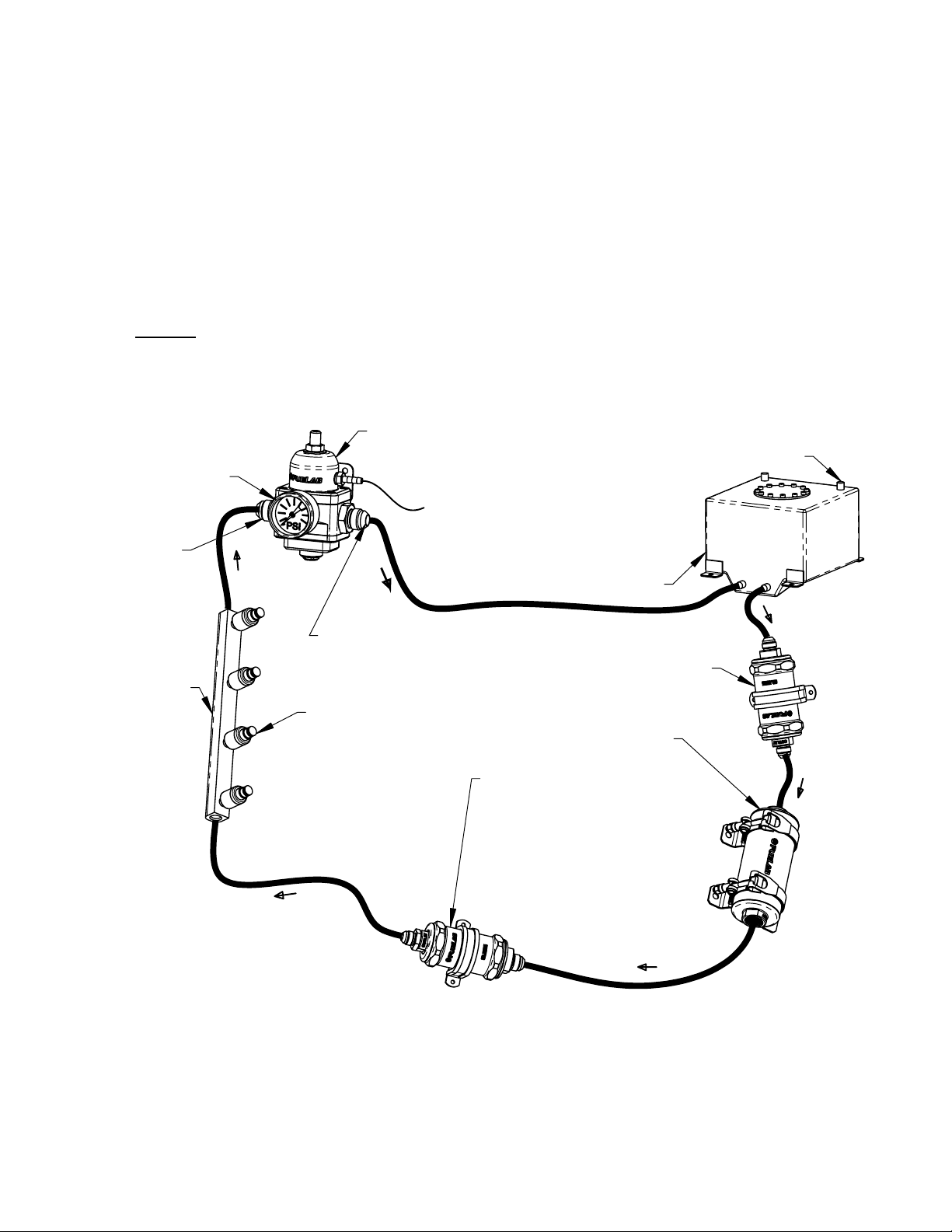
Plumbing Planning Notes:
”
p
Minimize plumbing restrictions between fuel rail(s) and regulator for peak performance, use –6AN (3/8”) to –8AN
(1/2”) line as required per flow rate requirements of the vehicle’s engine and fuel pump. EFI applications can use a
“Y” block or “T” fitting to split the output of the fuel pump into one end of each fuel rail (for dual fuel rail application)
then plumbed into the single inlet port. Use of a –8AN (3/8”) return line is typically recommended for this model of
regulator. See diagram on next page as well as diagram below, to identify the ports used on the regulator. The fuel
line used must handle high pressure. The use of fuel line such as stainless steel braided line and “AN” style fitting
connections is recommended. The fuel ports (one –8AN Inlet Port and one –8AN Return Port) use “AN” or “military
style fittings. This plumbing standard is commonly used with racing and high performance applications. See step 6
on next page for additional information on this port standard. A fuel filter with a 60 micron or lower particle rating is
required to be used upstream of regulator and downstream from fuel pump to protect it and the fuel injectors from
foreign object damage. Reference the Schematic Diagram below for filter locations. Use of a liquid filled gauge
exposed to engine compartment heat is not recommended as the liquid inside the gauge may exert measurement
errors. DO NOT plumb gauge port to any gauge mounted inside the vehicle or in passenger compartment. A line
burst can spill fuel inside passenger compartment and on occupants, possibly causing serious injury or death. An
electric gauge or pressure transducer system is recommended for readings in a passenger compartment.
Typical EFI Fuel System Schematic Diagram:
Fuel Gauge Shown in
Gauge Port, Liquid Fille d
Gauge may have Error Due
to Temperature Variations.
52902-c Regulator
To Engine Intake Manifold
Follow Fuel Cell Manufacturer's
Recommendations for Proper
Cell Vent Plumbing
Inlet Fitting
on Left Side
Vented Fuel Cell or Fuel Tank.
Tank must be Plumbed According
to Maximum Pump Flow Rate.
Consult Pump Manufacturer's
Specifications and Recommendations.
Fuel Rail
with Injectors
Return Fitting
on Right Side,
DO NOT REMOVE!
Multiple Rails can be plumbed
using "T" Fitting or "Y" Block.
Dual Inlet Regulator is Not
Required, as Changes in
Flow Rate through
Regulator are Very
Small when Compared
to other Bypass Style
Regulators.
Fuel Straining Filter Required, Typical
Micron Rating: 75-150, Fuelab
75 Micron Filter Recommended.
Fuelab Prodigy Series
Fuel Pump REQUIRED!
(Regulator Accepts Up
to Two Prodigy Pumps)
Fuel Filter with 60 Micron or
Lower Particle Rating is Required.
Fuelab Filter with 6, 10 or 40
Micron Rating is Recommended.
Check Valve Required for Reduced
Vehicle Emissions and Improved
Engine Starting. Fuelab 848xx
and 858xx Series Filter has Check
Valve Assembly Built in.
Installation Steps:
1. Disconnect the ground terminal from battery and allow the vehicle’s engine and exhaust system to cool.
Relieve fuel system per applicable service manual. Follow all Warnings and Cautions written on previous page
of these instructions.
2. Modify, remove or replace other fuel system components as required per established build plan (reference
notes on previous page and above).
3. Use the supplied bracket as a drilling template to mark holes for mounting bracket. Choose a location that
minimizes exposure to excessive heat, near fuel rails. Mounting bracket can be modified as required. Use
clear or colored enamel
aint to protect bracket surface after any modification.
109020122-1, No Rev Sheet 2 of 6
Page 3
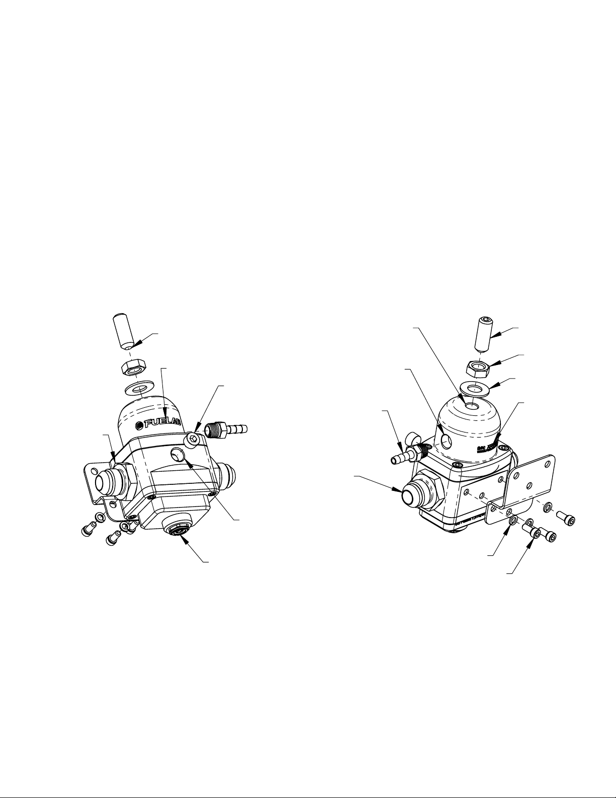
4. Apply li ght oil on t o the threads of the Adjustment Screw. Smal l amounts of air leakage in the adjustment
hardware may be pr esent during operation. T hi s is a normal operating condition. Thread t he Adjustment
Screw by hand until a slight tension is felt, this position is the minimum pressure setting. Do not tighten screw
any furt her. Pressure is to be adjust ed later in these instructions . Install the F lat Washer, th e n th e Ja m Nut.
Tighten the Jam Nut ha nd tight for later adjustment.
5. Install Bracket to regulator using supplied Br a c ket Sc rew s and Bracket Lock Washers. Tighten Brac ke t Sc rews
between 25-40 in · oz of torque (snug, do not over tight en screws). For m ounting di rect l y to hi gh vibratio n
source such as the vehicle’ s engin e, use rubber vibra tion dampening mounts for attac hing bracket to vehicle.
6. Refer to Page 5, Electrical Planning Notes. Wire provided Electrical Plug and Wire, as shown in notes. Use
solder and shri nk wrap for all wire splices. Foll ow all instr uctions prov ided with Prodigy Fuel Pum p as well,
referring to all proper electrical connections.
7. Use Teflon
®
tape or thread sealant on all 1/8”-NPT fittings to be used for the Gauge Port and Pressure
Reference Port (see diagrams, below). Inst all fitt in gs or plug as r equir ed. If pressure reference port is not
plumbed to the intake manifold (for typical EFI applications, port is plumbed to the intake manifold) then install
the Ba r b e d Fi ttin g (suppli ed) and allow fitting to vent to atmosphere (do not pl umb or pl ug po rt) . Do not use
®
Teflon
tape or thread sealant on i nl et or return fittings. Return F i tt in g can NOT be substituted, if fitting end is
damaged, then valve assembly must be replaced.
8. Install regulator assembly into vehicle, fastening the bracket to th e vehicle. Attach fuel lines, Gauge Port line (i f
external pressure gauge is used in a pplic ation) a nd Pressure Reference Port line (if applicable). Boosted
applications (such as turbo or superch arger) will require a hose clamp on barbe d fitting to prevent hose from
coming loose. Use of –3AN or –4AN fitting and line can also be used as a su bstit ute to the barbed f i tt in g.
-8AN Inlet Port
Fitting (supplied
and installed,
can be Substitute d
with other fitting)
Install with Cup
toward Regulator
Front
(Logo)
Spring Guide Ball may appear to be Off-Center.
Adjustment Screw Centers this Part upon Installation.
1/8"-NPT Pressure
Reference Port
(Engine Vacuum
Typically, for EFI)
Gauge Port Plug
(can be substitued
for gauge fitting)
(1/8") Barbed Fitting
(can be substituted
with other fitting)
-8AN Return
Fitting / Valve Assy
DO NOT REMOVE
(supplied
and Installed)
OR REPLACE!
Adjustment
Screw
Jam Nut
Flat Washer
Unique Serial
Number
Identification
1/8"-NPT Gauge Port
Electronics Connector
(3x) Bracket Lock Washer
(3x) Bracket Screw
9. Inspect fuel system for any contact of fuel lines or wires with other components that can cause chafing or
rubbing. Sec ure all components and fuel lines.
10. Connect the vehicle’s battery. Turn on fuel pump (typical l y by bypassing fuel pump re la y) without engine
operating. ECU or engine management computer may be contro lling the relay. The ECU may only operate
pump for a few seconds each time ignition swi tch is set to on. The pump will have t o operate several seconds
(30+) to prime and dr ive air out of the fuel system . Fuel sys tem pressur e should read about 15 PSIG (use an
external gauge for adj ustment if a permanent gauge i s not used). Inspect vehicle f or any leaks. Tu rn off fuel
system and repair any leaks that may be present before continuing.
11. When adjusting pressure, be sure that fuel pump i s operating to m on itor pressure. Increase pressure by
rotating adjustment clockwise. Do not thread Adjustment Screw past jam nut wi thin 1/8”. Over t i ghtening the
adjustment screw can damage the regulator. It is recom mended to use a “baseline” pressur e reference when
adjusting the pressure (adjusti ng the pressure with engine off or Pressure Reference Line unhooked). T he
vehicle’s engine may not produce consistent vacuum during idle to have repeatable readings.
12. Af ter final adjustment of fuel p res sure, tighten Jam Nut. Road test vehicl e, and retest pressure upon return to
ensu re a ccu ra te adj u stment.
109020122-1, No Rev Sheet 3 of 6
Page 4

How does the Electronic Regula tor W ork?
r
Just like standard EFI regulators, these regulators begin to relieve pressure (back to the fuel tank) once the set
pressure is achieved. As more and m ore flow is sent thr oug h the regulator (p ressur e climbs a little higher with extra
amount of flow), the regul ator relieves the excess flow back to the fuel tank . Our Patented El ectro nic Regulator (pe
U.S. Patent 7,810,470) takes this action one step further by placing a rest rict ion valve along the re t urn line (a
special valve is incorporated into the return li ne fitting of the regulator, DO NOT REP LACE this fitting with another
component, as this will force the operation of the system to go into high speed pump operation only).
The electronics monitors the built-up pressure and controls the Prodigy Fuel Pump accordingly. If the pressure that
is being read is too hi gh, then the Prodig y Pump is s ignaled to slow down. If the pressure is too low, t hen the
Prodig y Pump is signaled to speed up. This action not only allows t he pump to operate at a r educed amount sp eed
with low eng ine output, but also allows the return line flow rate to be relatively constant. T hi s has a n effect of
negating the regulator’s inherent mechanical regulation slope (This value is the amount of fuel pressure change per
amount of flow rate diff erence through the regulator) .
An additional output from the El ectr onic Regulator can be used to trac k the f u el system operating condition. Thi s 05 Volt analog output allows t he user to use a data acquisi tion system, Engine ECM, general data l ogger, or si m pl y a
volt meter, to track how hard th e pump i s si gna le d to op erate. The vol tage is typic ally at about 1.5 to 2.0 Volts
(depending on Pump Model used and other factors such as baseline fuel pressure) while engine is operating at idle
condition. Typical full capacity has an output of approxi m ately 4.5 V ol ts.
This regulator controls the fuel pump directly. Because of this, variation of pitch and sound quality radiating from
the fuel pump is to be expected, that is normally absent from traditional EFI fuel systems. Some small amounts of
oscillation duri ng operation may be present at various operating conditions. Initial starting typically calls to the
pump to start in a ful l speed condition, until fuel pressure is achieved, when speed is greatly reduced. T his too is a
normal operating condition.
A Look In sid e :
DO NOT DISASSEMBLE!
NO USER SERVICABLE INSIDE!
FOR INFORMATIONAL PUPOSES ONLY!
Adjustment Hardware
Regulator and Diaphragm
Assembly (This Section
Operates as a standard
EFI Mechanical Regulator)
Standard Inlet Fitting
Return Line Back-Pressure)
(installed)
This Fitting can
be Substituted
Pressure Transducer
(Used to Monitor
Relief Valving, Required
to Build Return Line Back-Pressure
Electronics Package
Hardware Shown Installed
(Bagged Separately)
Return Line Fitting
(installed)
This Fitting CANNOT
be Substituted!
4-Pin Connector
Mates with Included Plug and Wire
109020122-1, No Rev Sheet 4 of 6
Page 5

Electrical Planning Notes:
Use Mal e Connect or with wire (Pro vided with Regulator), to a llo w a sealed el ect rical connect ion to the El ect ronic
Regulator. The regulator requires very little power, and does not control the input power to the fuel pump. Follow
the Wiring Schemati c Diagram provided wi t h the Fuelab Prodigy Series Fuel Pum p, to properly wire power and
ground leads to pump.
Electrical Wiring Schematic (Le ss Power Supply and Ground to P ump):
Model 52902-c
Device (Not Supplied) is
not required, however can
be used to track general
fuel system output.
Compatible with
Fuelab Prodigy Series
Fuel Pump(s) ONLY!
(Not Supplied)
See Prodigy Instructions
for Proper Power Connections
From
From
+12V
+12V
Source
Source
IGNITION
IGNITION
SWITCH
SWITCH
DAQ System or
Data Logger
(16-20ga)
(16-20ga)
Insulate this
Insulate this
wire, if not
wire, if not
White (16-20ga)
White (16-20ga)
Fused Circuit
Fused Circuit
(1-5A)
(1-5A)
Green
Green
in use.
in use.
Signal Input
Black (16-20ga)
Black (16-20ga)
Red (16-20ga)
Red (16-20ga)
Electronic Regulator
Electrical Plug
and Wire
(Supplied)
TROUBLESHOOTING:
Problem Possible Cause Possible Solution
Not operating or
sli ght “cli cki n g ”
sound from pump
when turned on .
• Faul ty fuel pump relay.
• Faulty, dirty or corroded
terminals or im properly sized
wire.
• Debris from tank or plumbing
Check voltage to f uel pump, at power terminals. If
voltage is steady and consist ent (withi n ½ Volt of
battery) then contact Fuelab for repair. If voltage
is inconsistent as described, repair or replace
electrical components as required.
lodged inside pump.
Speed of pump
changes up and
down very
noticeably and
• Incorrect wiring of s peed control
as specified i n wiring sche matic.
• Loose terminal or wiring of
speed control c ir cuit.
Unhook speed control wiring from yellow terminal
of pump. Turn on pump; if operation is consistent,
then repair or replace components as required.
erra tica lly.
Loss of fuel
pressure or erratic
pressure pulsation
after several
minutes of
operation.
• Cavitation (vapor lock) due to
overheating or restricted inlet.
Check temperature of pump right after failure. If
pump is hot to touch (cannot leave hand on pump
due to it being too hot), then follow proper speed
control wi ring example, or look for other sourc es
of heat such as exhaust . If pump is not hot to the
t o u ch, chec k f o r i n l e t re str icti ons such a s
improperly vent ed tank, kinks in the fuel line, or
too small of plumbing for applicati on. Contact
Fuelab, as pump may be damaged due to
improper operating condition.
Not building up f u el
pressure.
• Incorrec t fuel system initial
priming procedure.
• Loose inle t fuel fittings or
Repeat procedure for proper priming. If condition
continues, check all plum bing upstream (on inlet
side) of fuel pump.
leaking plumbi ng on inlet si de.
Fuel pressure
drops off under
heavy engine l oad ,
particularly in
• Incorrect wiring of s peed control
as specified i n wiring sche matic.
• Loose terminal or wiring.
• I nsu ffi cien t fue l cap a ci ty.
Make sure pump i s operating at full speed while
under high engine load. If condition continues,
upgraded pump capacity is requi red.
higher gears.
109020122-1, No Rev Sheet 5 of 6
Page 6

LIMITED WARRANTY
FUELAB, a division of FCP, Inc.
62056, USA
Limited Warranty
1.
Manufacturer warrants that the Products sold hereunder will be free from defects in material and workmanship for a
period of 2 Years from the date of purchase to the original purchaser. If the Products do not conform to this Limited
Warranty during the warranty period (as herein above specified), Buyer shall notify Manufacturer in writing, or by
phone, of the claimed defects and demonstrate to Manufacturer satisfaction that said defects are covered by this
Limited Warranty. If the defects are properly reported to Manufacturer within the warranty period, and the defects
are of such type and nature as to be covered by this warranty, Manufacturer shall, at its own expense, furnish
replacement Products or, at Manufacturer's option, replacement parts for the defective Products. Removal of
Products from vehicle (
combustion engine. This product is
shipping to Manufacturer and installation of the replacement Products or replacement parts shall be at Buyer's
expense.
Other Limits
2.
THE FOREGOING IS IN LIEU OF ALL OTHER WARRANTIES, EXPRESS OR IMPLIED, INCLUDING BUT NOT
LIMITED TO THE IMPLIED WARRANTIES OF MERCHANTABILITY AND FITNESS FOR A PARTICULAR
PURPOSE. Manufacturer does not warrant against damages or defects arising out of improper or abnormal use or
handling of the Products; against defects or damages arising from improper installation (where installation is by
persons other than Manufacturer), against defects in products or components not manufactured by Manufacturer,
or against damages resulting from such non-Manufacturer made products or components. Manufacturer passes on
to Buyer the warranty it received (if any) from the maker thereof of such non-Manufacturer made products or
components. This warranty also does not apply to Products upon which repairs have been effected or attempted
by persons other than pursuant to written authorization by Manufacturer.
("Manufacturer") warrants its
.
Vehicle means any automotive, bike or marine transportation powered by an internal
.
, having its principal place of business at
FUELAB
intended or designed for use on aircraft, experimental or otherwise.),
NOT
products (the "Products") as follows:
826A Morton Court, Litchfield, IL
Exclusive Obligation
3.
THIS WARRANTY IS EXCLUSIVE. The sole and exclusive obligation of Manufacturer shall be to repair or replace
the defective Products in the manner and for the period provided above. Manufacturer shall not have any other
obligation with respect to the Products or any part thereof, whether based on contract, tort, strict liability or
otherwise. Under no circumstances, whether based on this Limited Warranty or otherwise, shall Manufacturer be
liable for incidental, special, or consequential damages.
Other Statements
4.
Manufacturer's employees, representatives' and/or resellers ORAL OR OTHER WRITTEN STATEMENTS DO NOT
CONSTITUTE WARRANTIES, shall not be relied upon by Buyer, and are not a part of the contract for sale or this
limited warrant y.
Entire Obligation
5.
This Limited Warranty states the entire obligation of Manufacturer with respect to the Products. If any part of this
Limited Warranty is determined to be void or illegal, the remainder shall remain in full force and effect.
Warranty Service
6.
What Does This Warranty Not Cover?
flood) is not covered. Also, consequential and incidental damages are not recoverable under this warranty. Some
states do not allow the exclusion or limitation of incidental or consequential damages, so the above limitation or
exclusion may not apply to you.
How Do You Get Service?
Registration card, or register on-line at www.fuelab.com/warranty within 30 days of purchasing the Product.
If something goes wrong with your product contact FUELAB at 1-800-541-2345, International customers call 001-
217-324-3737, for a Return Authorization Number (RMA). After receiving your RMA send it postage paid, fully
insured, with a brief written description of the problem to:
.
.
.
Any problem that is caused by abuse, misuse, or an act of God (such as a
In order to be eligible for service under this warranty you
MUST
return the Warranty
FUELAB Warranty Department, 826A Morton Court, Litchfield, IL 62056
We will inspect your Product and contact you within 72 hours of receipt to give the results of our inspection and an
estimate of the labor and/or parts charges required to fix the Product, if applicable. If covered under this limited
warranty Manufacturer will repair Product and return it to you at no cost. If the Product is NOT covered under this
warranty and if you authorize repairs, we will return the repaired Product to you COD, or prepaid via credit card,
within 72 hours. There is no charge for inspection. If return product is found to be free of defects a $25.00 shipping
and handling charge will be applied. We will return the repaired Product to you COD, or prepaid via credit card,
within 72 hours.
109020122-1, No Rev Sheet 6 of 6
 Loading...