

Page 1
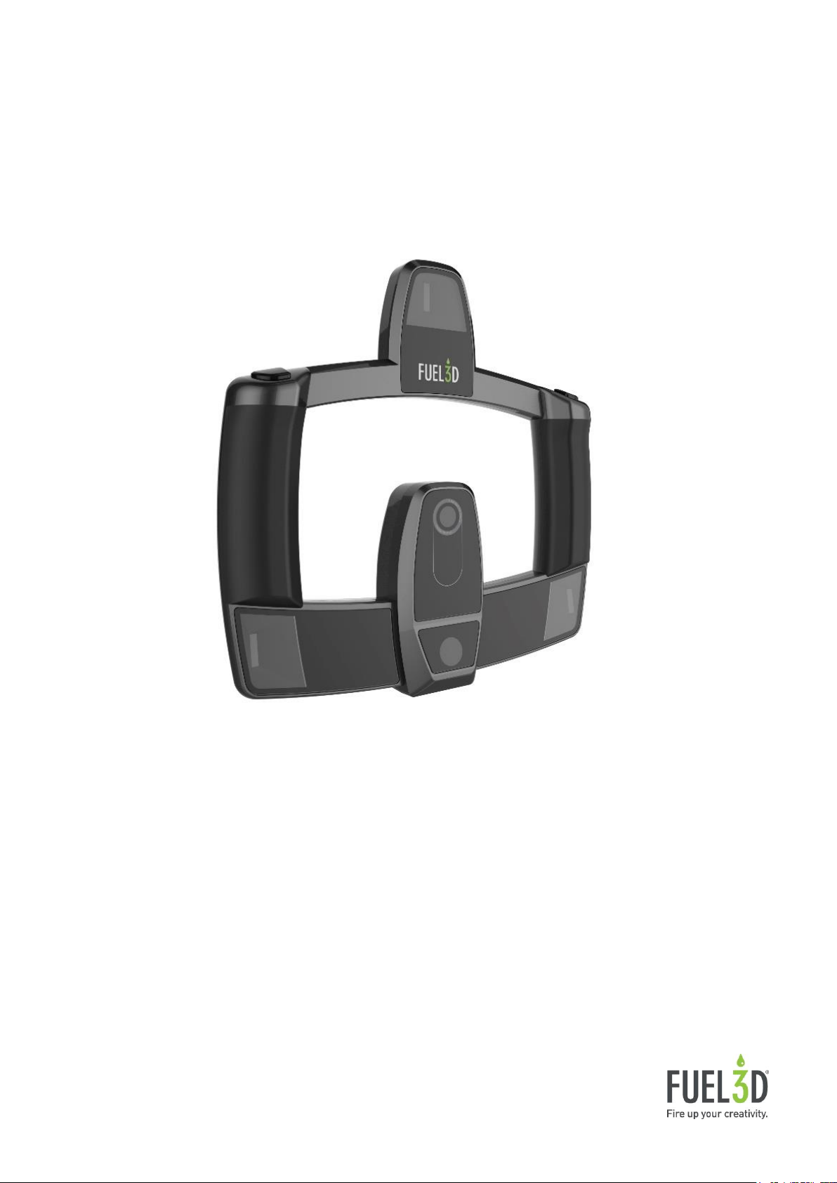
User Manual
SCANIFY F3D2001
Version 2.1
Revision Date: 2016.01.18
© Copyright 2015 Fuel 3D Technologies Limited. All rights reserved. Fuel3D®, SCANIFY® and PELLEGO® are registered
trademarks in the name of Fuel 3D Technologies Limited. All other trademarks are the property of their respective owners. All
Fuel 3D Technologies Limited products and services are subject to continuous development. We reserve the right to alter
technical specifications without prior notice.
Page 2
1
Contents
SCANIFY Profile
3
Set-up
4
- Registering your device and locating your serial
number
4
- Setting up your scanner
5
- Identifying parts of your scanner
8
- Taking care of your scanner
9 Taking a scan
11
- Selecting a suitable subject
11
- Utilizing the targets
13
- Acquiring a scan with Fuel3D Studio software
17
Hardware
20
- Connections
20
- Flashes
20
- Cameras
21
- LED indicators
22
Software
24
- Navigating Fuel3D Studio software
24
- File management
27
- Acquiring a scan
29
- Inspecting a scan
29-30
- Reprocessing a scan
31
- Adjusting the Lighting
32
- Cropping a scan
33
- Exporting a scan
35
- Remeshing a scan
36-38
Page 3
2
Stitching Overview
39
- Interface explained
39
- Stitching, cropping, ordering
40-42
- Creating a stitch group
42
- Creating an automatic stitch
43
- Creating a manual stitch
43
- Completing the stitch
44
Troubleshooting
47
- Failed scans
47
- Cuts in your scans
48
- Target troubleshooting
48
- Inaccurate geometry
48
- Workarounds
48
Page 4

3
SCANIFY Profile
SCANIFY® is a handheld, point-and-shoot 3D scanner built to enable consumers and
professionals to 3D scan objects in high-resolution shape and color in a tenth of a second.
Software - SCANIFY comes with Fuel3D Studio software, which allows scans to
be manipulated and exported as popular file formats for 3D printing and on-screen
applications (.STL, .OBJ, .PLY). All versions of Fuel3D Studio software are created to
be as easy to use as possible, with a simple, intuitive user interface that can be
installed on both PC (currently available) and Mac (coming in late 2015).
Minimum hardware specification:
For the best performance we recommend running a later i3, i5 or i7 processor
o Studio Starter - 2GB RAM, 1GB hard disk space, Dual-core processor.
o Studio Plus - 6GB RAM, dual-core 64bit CPU 2GHz, dedicated graphics card.
o Studio Advanced - 10GB of RAM, Quad-core 64bit CPU 2.3GHz, dedicated
graphics card.
Recommended hardware specification: 12 GB RAM, 500 GB hard disk, Intel i7
or better processor with a dedicated graphics card.
Operating system support: Studio software has been tested on Windows 7, 8, 8.1
and 10. For the advanced versions of Studio software an x64 version of Windows is
required.
Object specifications:
o SCANIFY is the perfect solution for quickly capturing 3D models of:
The human form
Fabrics
Stone and masonry
Wood carvings
Stone sculptures
Plants and trees
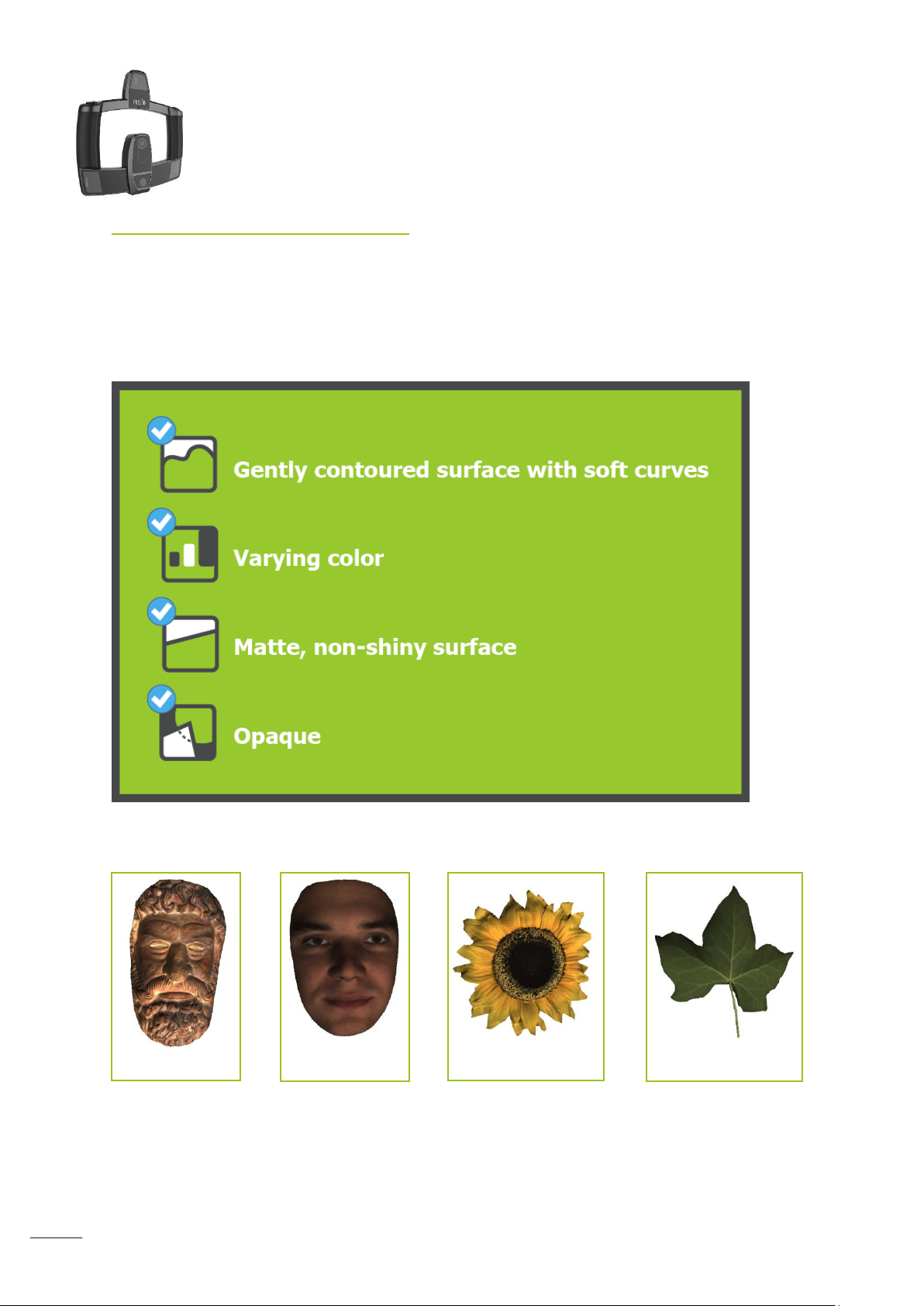
o Ideal objects for scanning include the following characteristics:
Gently contoured surface with soft curves
Varying color
Matte, non-shiny surfaces
Opaque
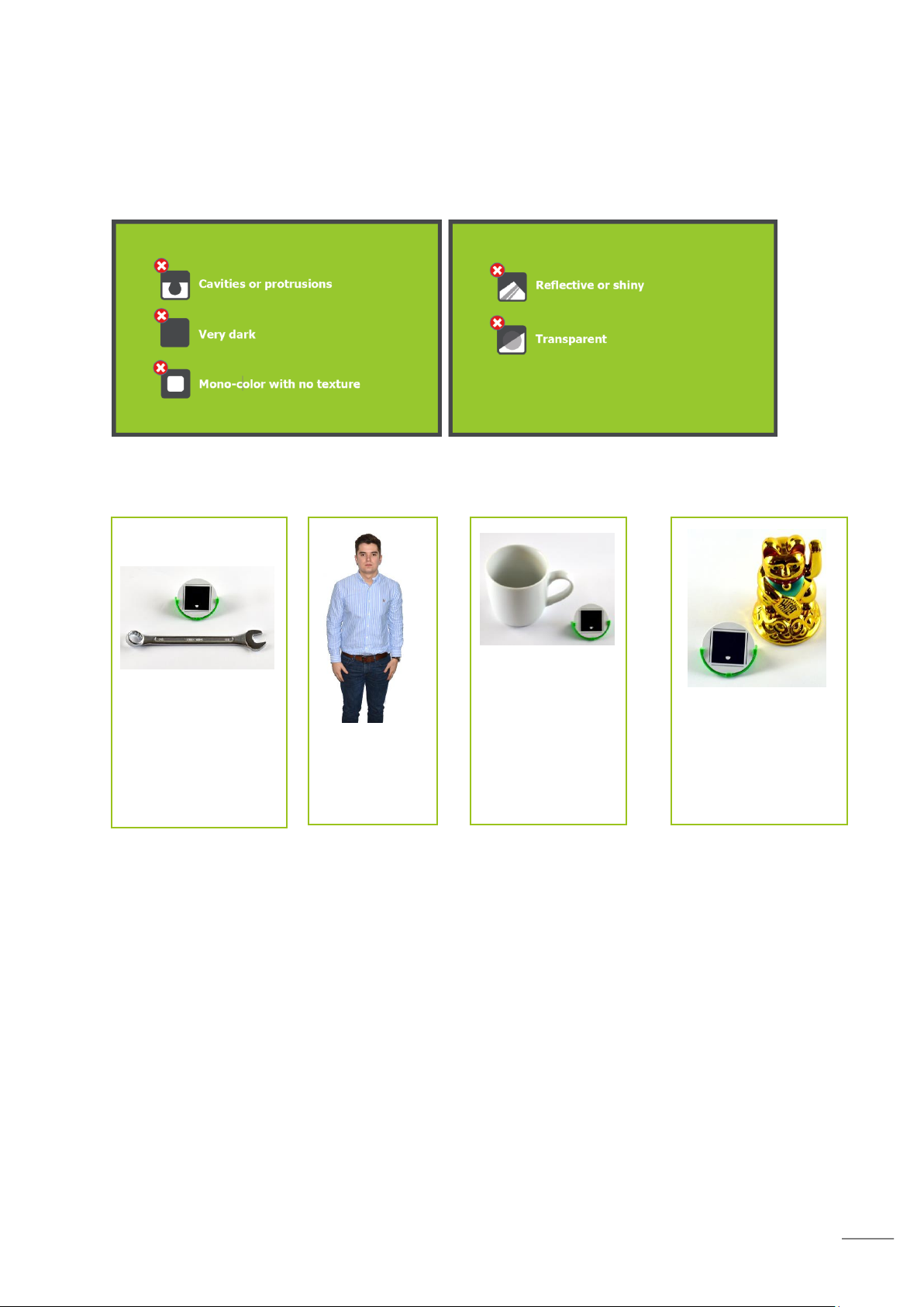
o Objects with the following characteristics may not be suitable for scanning:
Cavities or protrusions
Very dark/black items
Mono-color with no texture
Reflective or shiny
Transparent
Sharp edges and corners
Page 5
4
Note:
If you are having problems registering your account please contact customer
support at: fuel3D.zendesk.com.
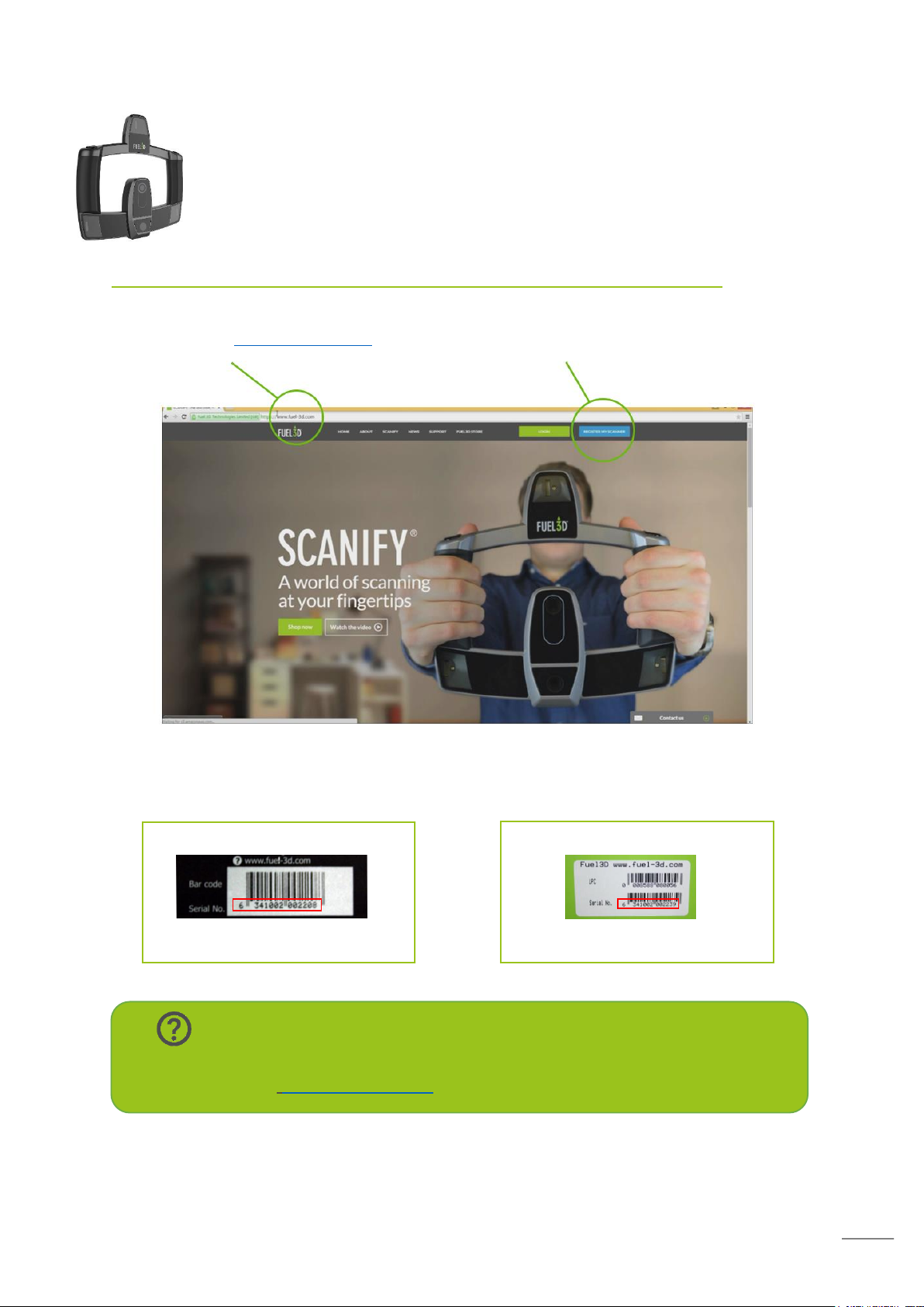
Find your serial on your scanner:
Example: 6341002002208
Find your serial on your box:
Example: 6341002002239
Set-up
Registering your device and locating your serial number
1. Head over to www.Fuel-3D.com; 2. Click the ‘REGISTER MY SCANNER’ button.
The serial number of your scanner can be found on your SCANIFY box as well as on the
back of the scanner itself, you will need it before you can download the Studio software, you
can optionally enter it during registration.
Page 6
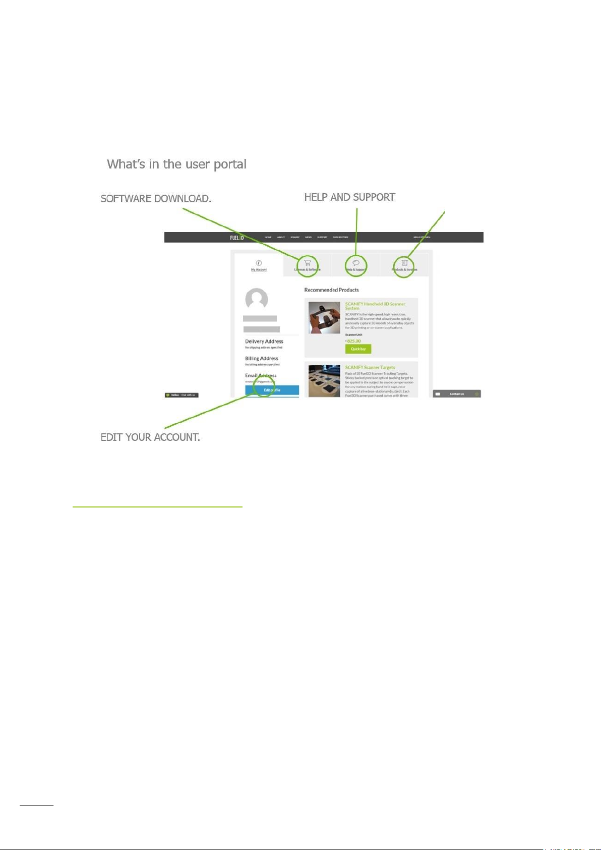
5
PRODUCTS AND
INVOICES
Once registered you will have access to the user portal where you can download software,
check your product licenses and access support.
Setting up your scanner
Software Installation
In the portal choose licenses and software and download Fuel3D Studio software. Prior to
any purchase of the Plus or Advanced licenses Studio Starter software must first be
downloaded.
IMPORTANT NOTE: You must provide your scanner serial number before the download
button will become available.
Page 7
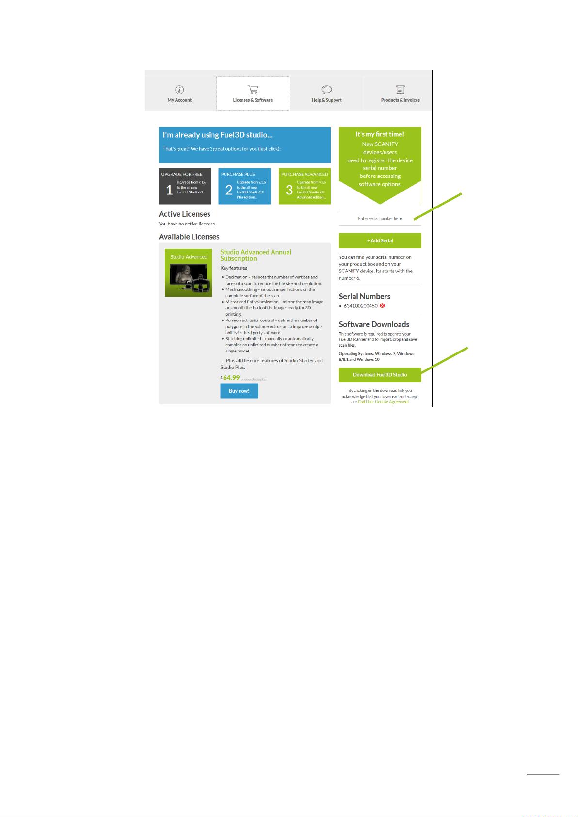
6
Software
Download
Be sure to enter
your Serial number
Once the download has finished please run the installation wizard. We recommend disabling
any anti-virus software and running the installer with administration rights during
installation.
Getting connected
The scanner requires two connections (included) to acquire a scan:
- 2.0 Micro USB to USB data cable
- 5V Power adapter
Page 8
7
Note:
Device drivers must be installed before opening Fuel3D Studio software, this
may take several minutes the first time a new scanner is connected.
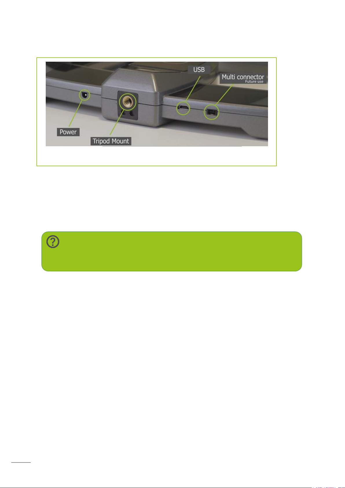
Both connections attach at the bottom of the scanner.
Select the appropriate power adaptor for your
region.
Plug the power adaptor into a wall outlet and the other end into the scanner. Plug the USB
into the scanner and your PC.
Once plugged into a computer Studio software will automatically install the device drivers.
Page 9
8
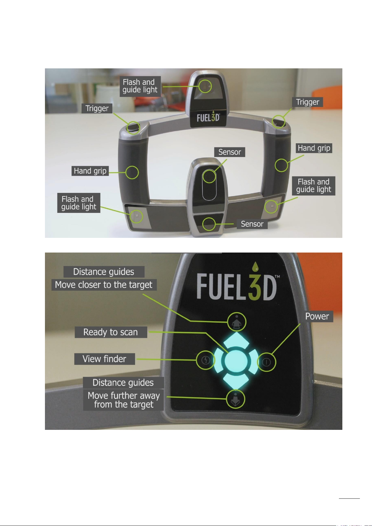
Identifying parts of the scanner
Page 10
9
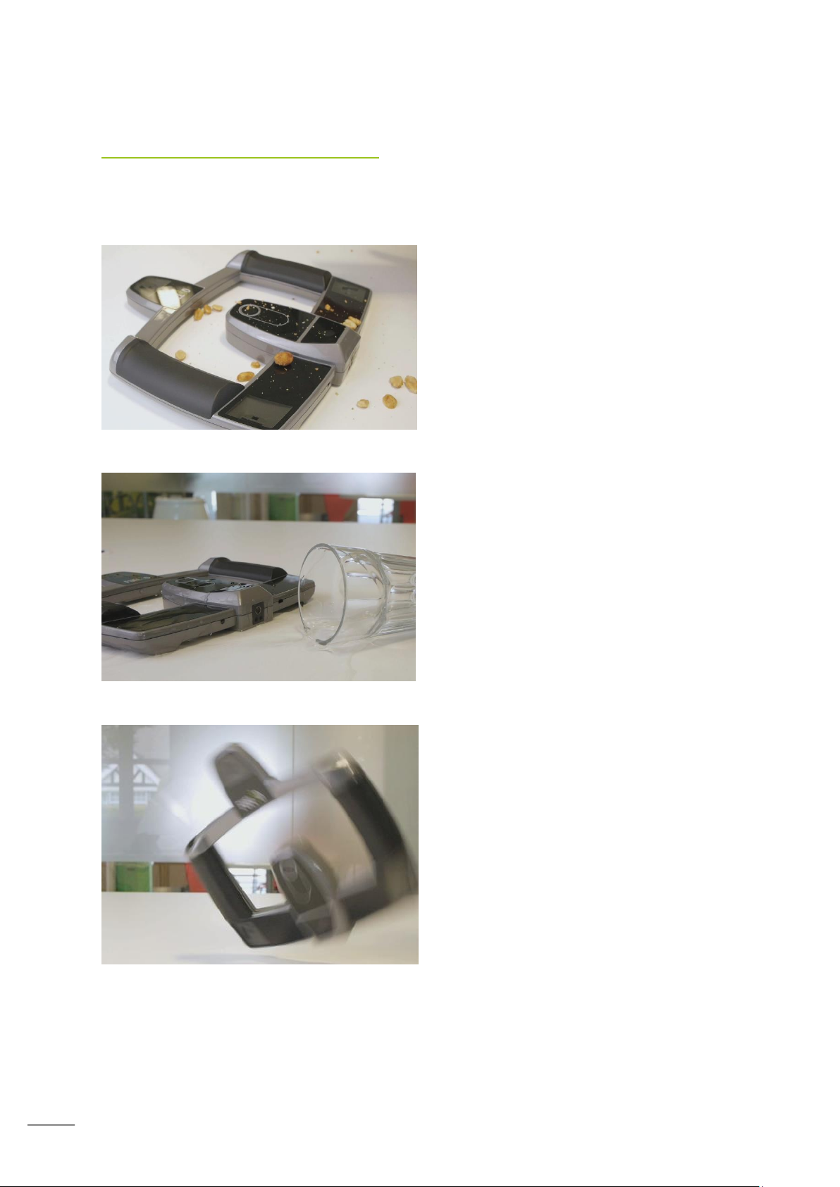
Get it dirty
Always ensure your scanners lenses
and flashes are clean and free of dirt,
grease fingerprints, dust etc. This can
affect your data quality and cause
scans to fail in processing.
Spill water on it
Never spill water on your scanner.
Drop it
Never drop, hit or impact your
scanner, this can degrade the
calibration.
Taking care of your scanner
Don’t
Page 11
10
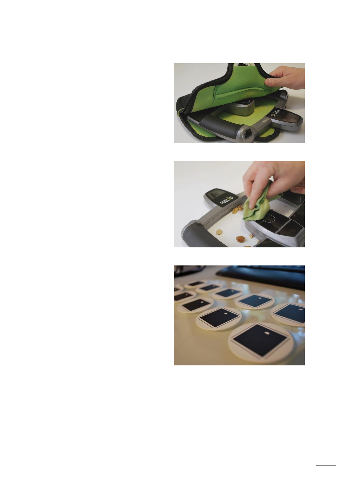
Do
Protect it when travelling
Always protect your scanner when
traveling. Protect your scanner with
the Fuel3D scanner pouch.
Keep it clean
Always keep the lenses and flashes
clean. This can be done using the
Fuel3D lens cloth.
Keep the targets in good
condition
Always ensure that your targets are
in good condition. Using targets that
are scratched, bent or deformed can
affect the data quality.
Page 12
11
Taking a scan
Masonry
People
Flowers
Plants
Selecting a suitable subject
Some subjects may work better than others and we encourage experimenting with a wide
variety of items to get an understanding of what scans best.
Below are examples that can help you decide whether a subject is suitable to scan.
Subjects that work well:
Examples that work well:
Page 13
12
Metallic – shiny or
reflective objects
will reflect the light
from the flashes
Too large – a
whole body
takes too
many scans
Lack of detail –
lack of surface or
color information
may result in
distortion in your
scan
Plastics – these
objects may be
reflective and lack
surface detail to
accurately capture
Subjects that may not work well
Examples that may not work well
Page 14
13
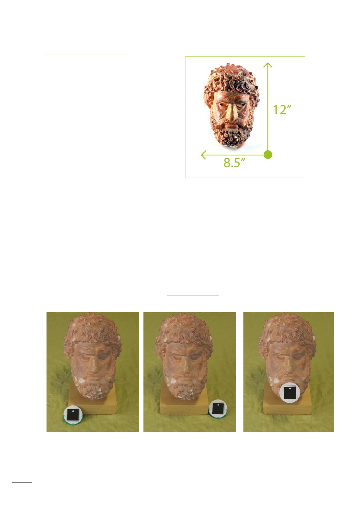
Utilizing the targets
Placement of the target
It is important to understand the scanners’
capture area when selecting a subject and
while scanning.
The scanner is able to capture a subject that
is around 37cm/14.5” diagonal. If your
subject is larger than this, multiple scans may
be taken and then stitched together to create
a 3D model. Please note that stitching is
available in Studio Plus and Advanced
software options only.
The target also ensures that you are within
the correct range of the subject you are
scanning.
Scanning an inanimate subject
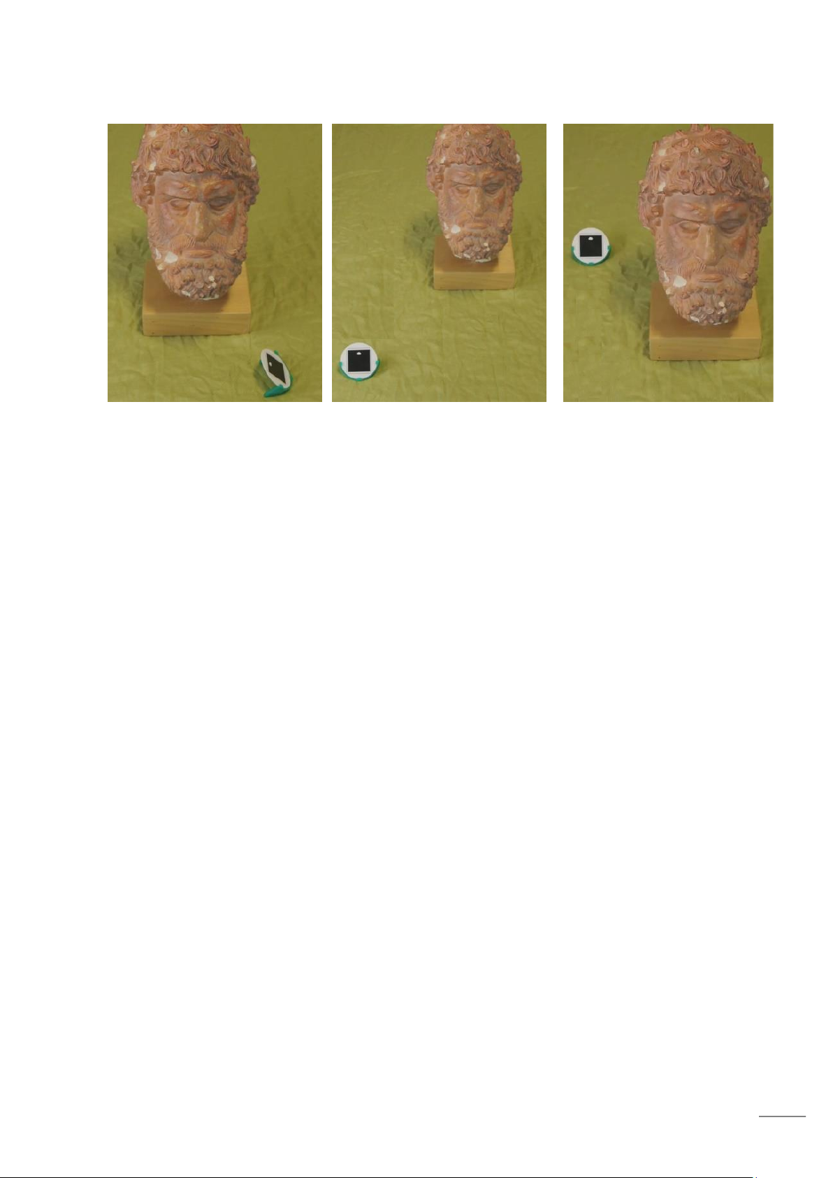
The target can be placed on the subject or to the side using, for example, the free standing
target holder.
It is important that the target is always facing towards the scanner.
You should not attempt to duplicate the target as this will cause errors when processing
your scans.
Additional targets can be purchased from www.fuel-3D.com
Good target positioning
Page 15
14
Bad target positioning
Page 16
15
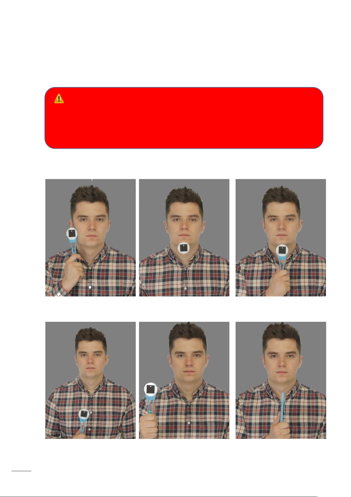
Scanning a live subject
Good Target Positioning
Bad Target Positioning
WARNING
Epilepsy Caution: The Fuel3D Scanner incorporates flashing lights which
may affect individuals who have photosensitive epilepsy or other such
conditions. Users must accept full responsibility.
Place the target so that it is touching the subject. This ensures that the target moves in
relation to the subject which will reduce the chance of generating a poor quality scan. When
scanning a persons’ face it is advised to use the handheld target holder and place it against
the chin.
Page 17
16
Tip:
Don’t worry if the target blocks part of your scan, you can crop it out later.
You may need to experiment with the target in different positions depending
on what subject you are scanning.
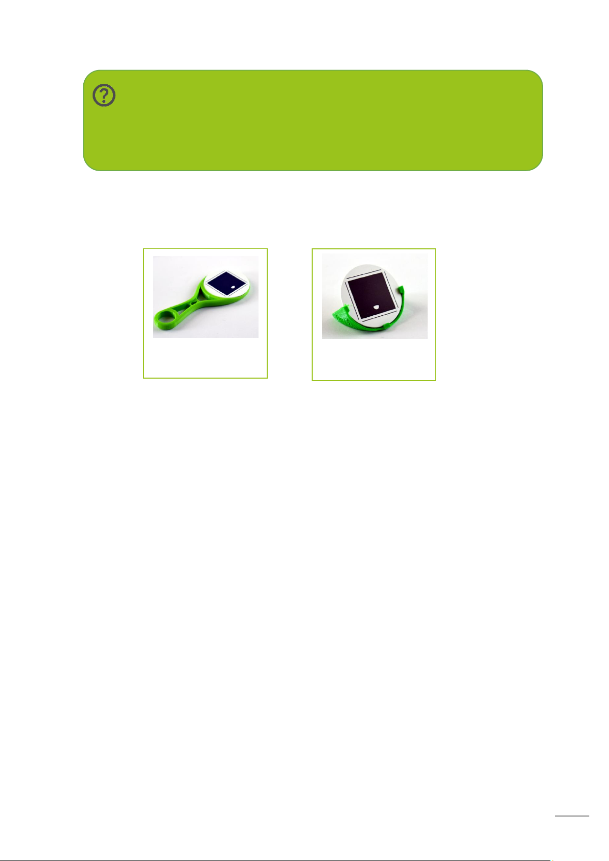
Handheld target
holder
Free-standing target
holder
To assist with the positioning of the targets you can download for 3D printing two target
holder types from the customer portal:
Page 18
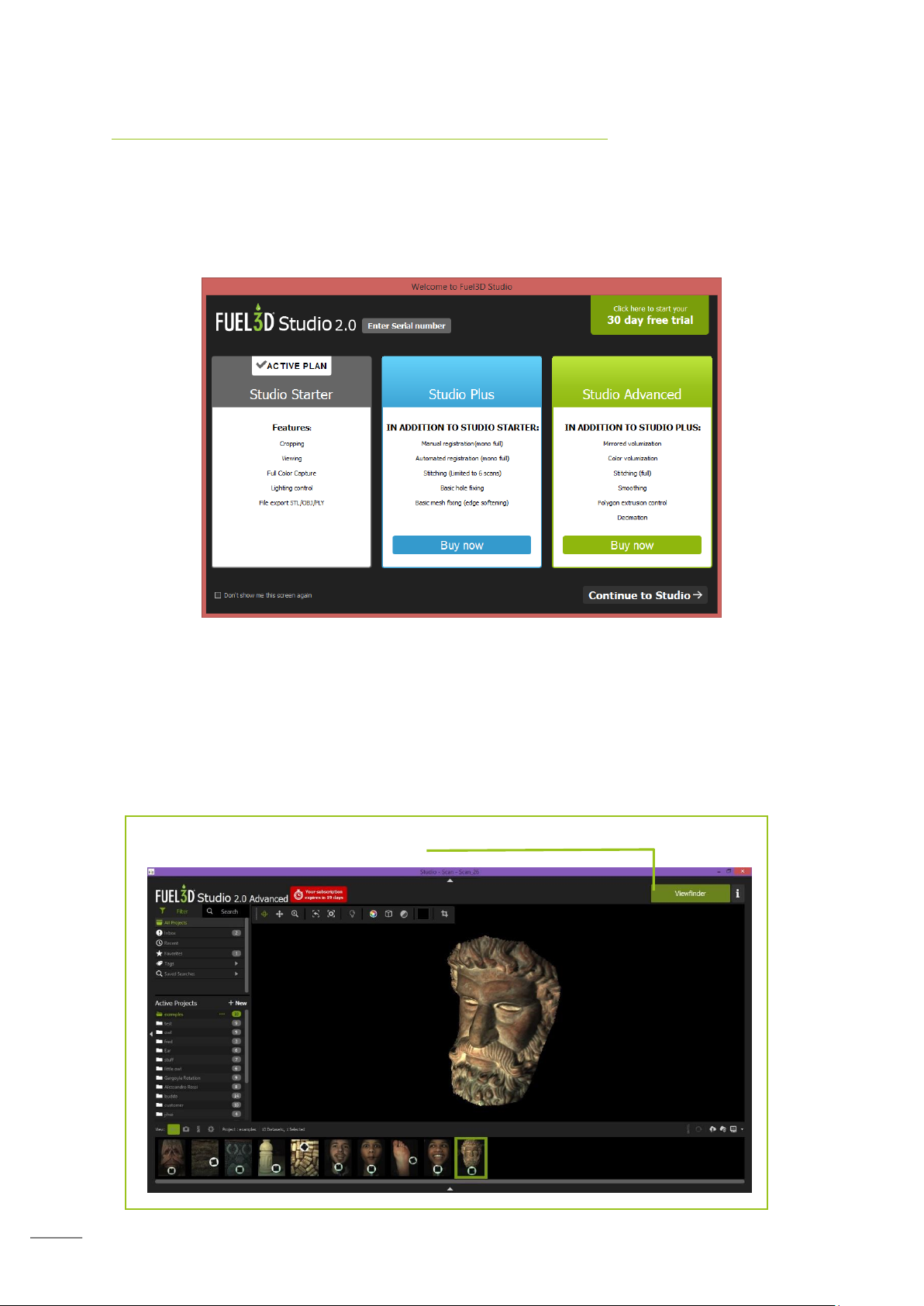
17
Acquiring a scan with Fuel3D Studio software
‘Launch Viewfinder’ button
First time launching Fuel3D Studio software
When you first launch Studio software you will be asked if you wish to add additional
functionality such as an upgrade or free trial. This screen can be deactivated by selecting
the checkbox at the bottom left corner of the dialog.
You can activate a one-time only free trial to experience the full suite of features at any
time.
Launching the Viewfinder
You can open the Viewfinder by selecting the ‘Launch Viewfinder’ button that is located at
the top right hand side of the screen.
Page 19
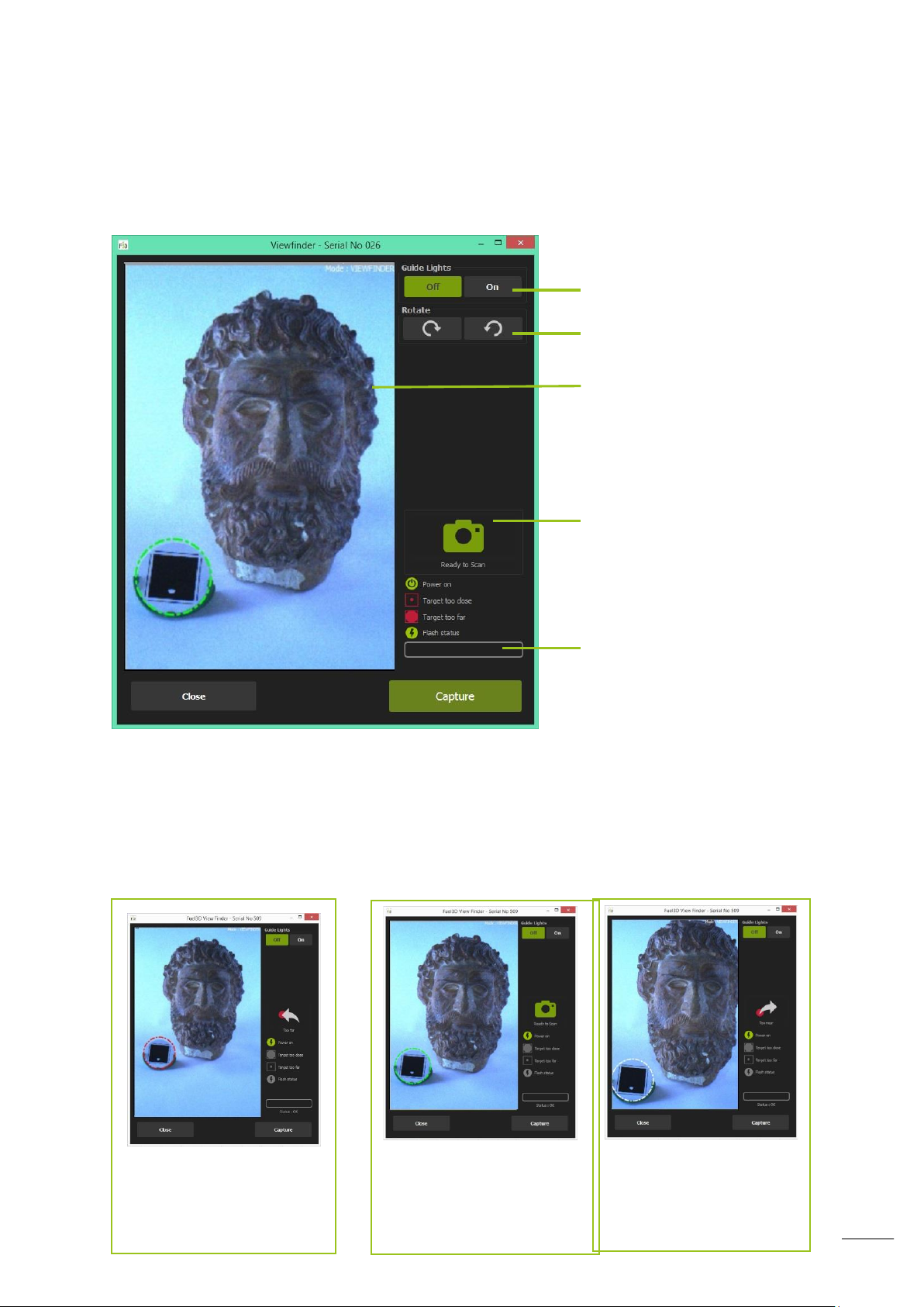
18
Red – Too far away from
the target (> 45cm/17.7”)
Green – Perfect distance
from the target
(35cm/13.7” –
45cm/17.7”)
White – Too close to the
target (< 35cm/13.7”)
Turns on the scanners guide
lights for use in low light
Preview window
Scan position and status
Flash recharge
Rotates the camera view
The Viewfinder will then display a live view from the scanner.
The Viewfinder
Target tracking in the Viewfinder
The target is required to take a scan. The Viewfinder has a tracking capability and displays
to you, via a ring around the target, the distance that you are away from the subject.
There are various methods of feedback in the viewfinder to correctly position the SCANIFY,
the target highlight color and the changing status icon on the side of the viewfinder.
Page 20
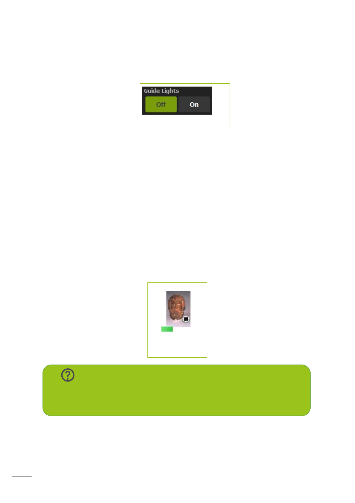
19
Ideal conditions for scanning would be indoors with standard home or office lighting. If
Guide light button
Your scan will
begin processing
Note:
Once a scan has been taken, it will take 15 seconds for the flashes to cool
down before you can take another scan. This is shown by the progress bar at
the bottom of the Viewfinder.
lighting is too dark you can use the guide lights. These are on by default whilst scanning but
can be toggled ‘Off’ or ‘On’ within the Viewfinder interface.
Ensure there are no lights or reflected lights in the scan capture area. Shiny objects, such as
jewellery, may also cause problems.
Capturing a scan
A scan can be captured once the scanner is in range of the target. To capture a scan you
can depress either of the triggers or click on the ‘Capture’ button in the viewfinder.
If you cannot properly see the item or the system is having a problem locking onto the
target you can half depress the scan button on the scanner. This will turn on the scanners
own lights and enable the scanner feedback.
Once a scan is captured a preview will be displayed in place of the live view. You can then
select whether to save or discard the scan.
Selecting ‘Save’ will begin the processing of the scan and will refresh the live view. You
won’t be able to view the scan until processing is complete. You can see the progress of the
processing via the timer in the lower pane, below the scan preview thumbnail.
Page 21
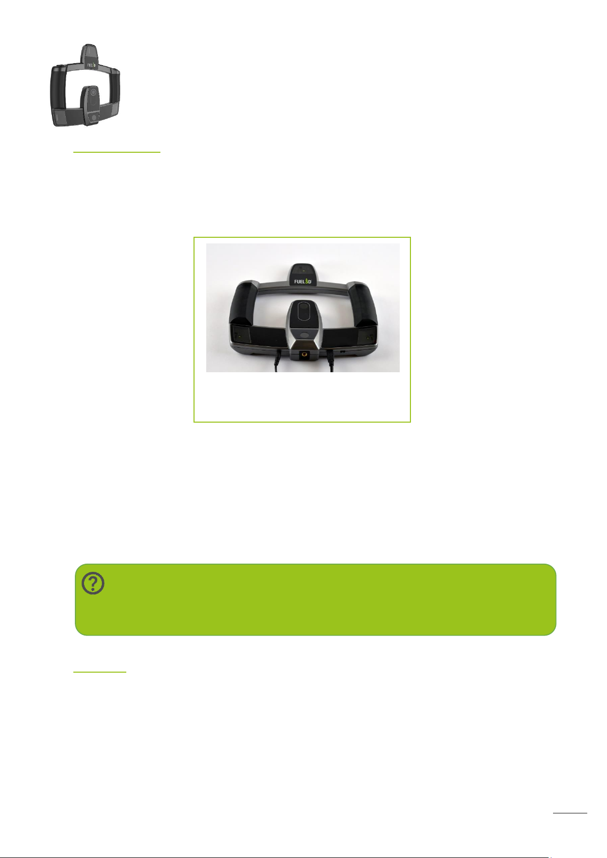
20
Hardware
Note:
The first time the scanner is plugged into your PC the drivers may take several
minutes to install.
Both connections attach at the bottom
of the scanner
Connections
To function the scanner requires two connectors (included):
- 2.0 Micro USB to USB data cable
- 5V Power Adapter
Select the appropriate power adaptor for your region. Plug the power adaptor into a power
outlet and the other end into the scanner. Plug the USB into the scanner and your PC.
Once the scanner is plugged into your computer it will automatically install device drivers.
Additional connections
1/4-20 UNC internal thread for screw tripod mounting.
Accessories connector (future accessories TBA).
Flashes
There are three light housings, one in each corner of the scanner. Each housing contains a
guide light, which can help illuminate the target and subject, along with a flash module
which is used during capture and processing.
The three flashes are used to illuminate the subject from three different positions during a
capture. This process takes less than 1/10th of a second.
Page 22
21
Cameras
Holding the scanner and using the trigger
buttons
Note:
Only one trigger is required to be pressed to take a scan. It is recommended
to use both as this helps to stabilize the SCANIFY and reduce the risk of poor
quality scans.
Tip:
Ensure that your camera lenses are clean.
Tip:
Ensure your hands are not covering the flashes while taking a scan.
The scanner uses a stereo camera set-up located in the centre of the scanner.
The central camera is utilized while using the viewfinder.
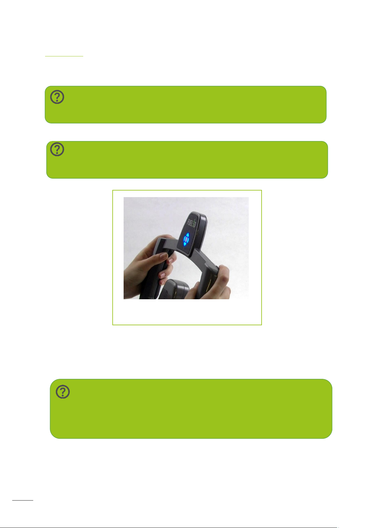
The Trigger Buttons
The SCANIFY has two trigger buttons located on top of the scanner. Used when taking a
The SCANIFY should be held with the cameras and flashes facing towards the subject.
Half press the trigger buttons to prepare for scanning. This will also turn on the guide lights
to assist in target location.
Page 23
22
LED indicators
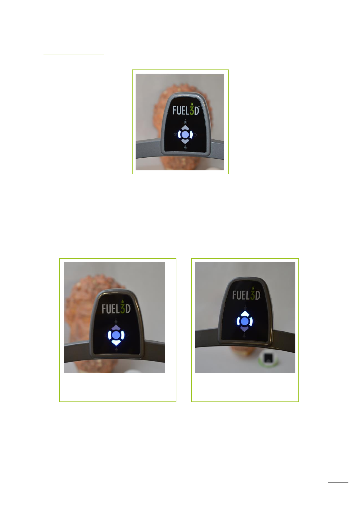
If the bottom LED flashes you must
move away from the target
If the top LED flashes you must
move closer to the target
The indicator LEDs face towards you while taking a scan.
The right LED will illuminate while the scanner is receiving power.
The left LED will illuminate when the Viewfinder is running on the computer.
The top and bottom LEDs can be used to help track the target by providing you with
feedback of when the scanner is in range of the target.
To activate the tracking LEDs the trigger buttons must be half-pressed.
As long as the target is in view they will provide guidance on the proximity of the scanner to
the target.
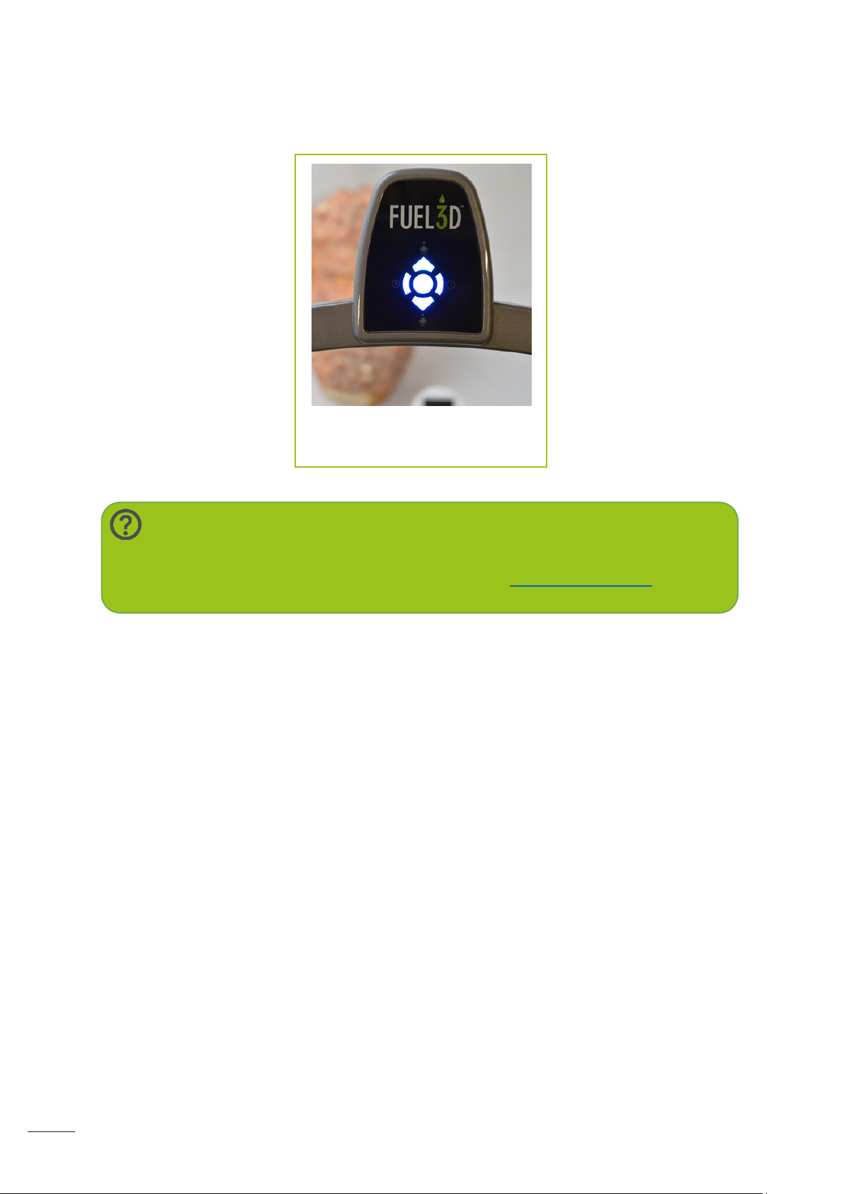
When you reach the correct range from the target then all LEDs will light-up.
The left LED indicates if the flash cool-down is active. If will flash rapdily if the flashes are
still in the cool down period and the trigger is depressed.
Page 24
23
Once the flash cool down period is complete the LED will become solid blue indicating that
Note:
If the left LED indicator flashes slowly while the target is in range and you are
unable to take a scan please contact support at: fuel3D.zendesk.com.
When all LEDs light up you are
ready to scan
your scanner is ready to take the next scan.
Page 25
24
Software
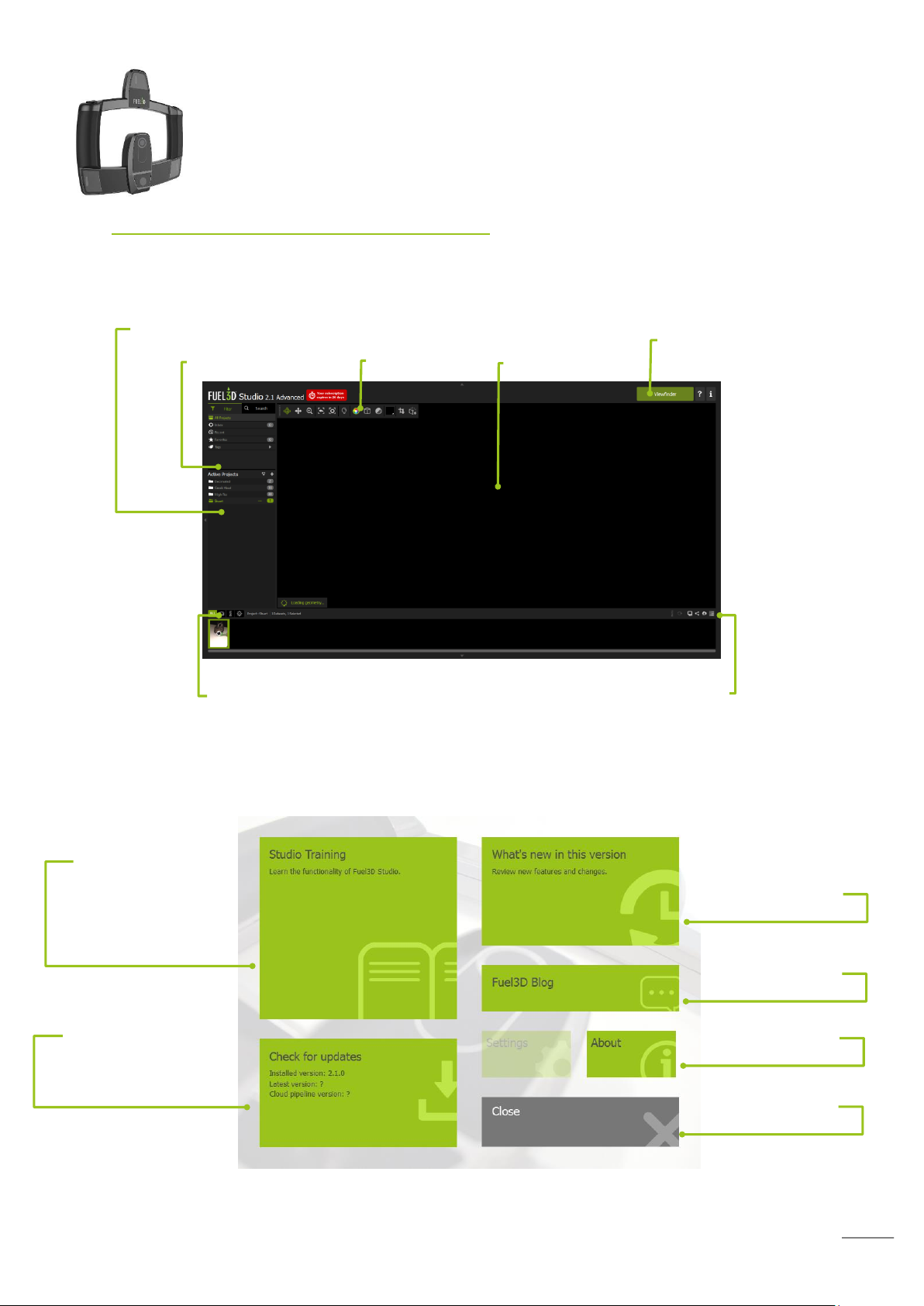
Filter and search
List of projects
View menu
3D scan viewer
Scan management options
Scan filter options
Viewfinder launch
Opens the Studio
Tutorial page
Click to check for
Studio updates
Close the landing
page
View the list of
Licenses used
Open the blog
View version
changelog
Navigating Fuel3D Studio software
The Fuel3D Studio software interface
The Landing Page
Page 26
25
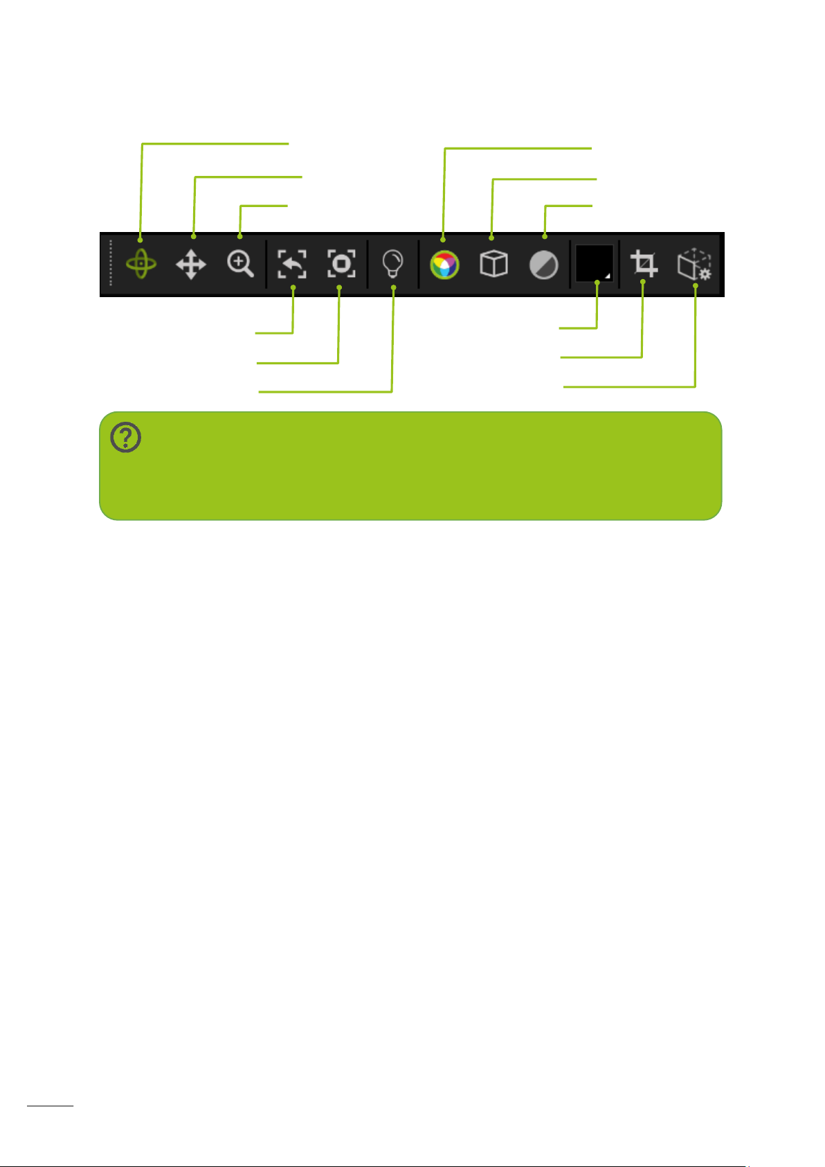
The view menu
Reset rotation
Set to target
Light Control
Rotate
Pan
Zoom
Color
Wireframe
Monochrome
Background
Crop tools
Remesher tools
Tip:
Whilst rotate is selected the left mouse rotates, the scroll wheel depressed
pans and zooms when scrolled.
Page 27
26
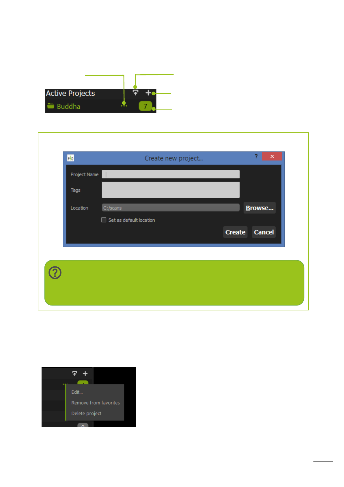
Managing projects
Add a new project
Edit project
Number of scans in project
Tip:
Tags enable you to add additional searchable information with the scan for
example the subject or location where the scan was taken.
Import project
Projects are where you wish to store you scans. We would recommend that you create a
project for each group of scans. You can then add tags to associate more information.
To create a new project select the new icon and complete the dialog
Your scans are saved within projects. You can create an unlimited number of projects
(dependent on your storage space).
To change project details click the dotted icon, a pop-up menu will allow you to Edit and
change the project name, Remove from favourites if you have set that and Delete the
project.
Page 28
27
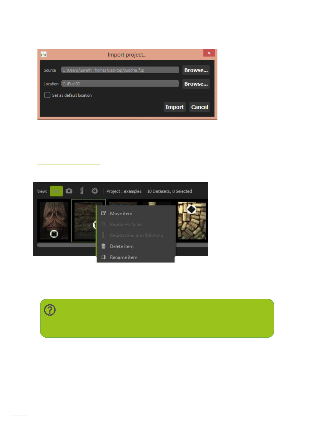
To Import a project click the arrow icon.
Note:
When you delete a scan it is NOT placed in the recycle bin it is immediately
removed!
IMPORTANT NOTE: This feature only supports import from the 32-bit version of Studio,
there is no export option currently available from the 64-bit Studio.
File Management
To access the tools to Move, Delete, Rename, Reprocess and Stitch files together use the
left mouse button to access the sub menu that will appear when the mouse is over the scan
you wish to work with.
When you choose to
move an item a pop-up
will appear that will ask
what project you wish
to move the scan to.
Reprocessing allows
you to re-apply the 3D
algorithms to the raw
scan data. This will
enable scans to be
updated and improved as
the 3D processing
improves.
The lower pane window
The lower pane is where you can browse and select your scans once you have selected a
scan in a project. Once selected they will open in the built-in 3D viewer.
Page 29
28
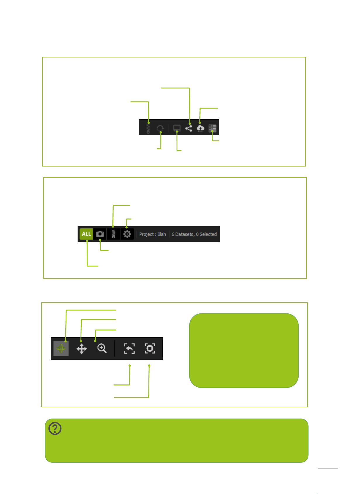
Reset Rotation
Set to Target
Note:
Rotating your scan in the 3D view will not alter the orientation after exporting
from Studio software.
Zoom
Scan panning tool
Scan rotation tool
Tip:
Whilst rotate is selected
the left mouse rotates
the scroll wheel held
pans and zooms when
scrolled
View publishing progress
Reprocess selected scan
Registration and stitching
Displays processing scans in the lower
Displays complete scans in the lower pane
Displays processing and complete scans in the lower pane
Cloud upload progress
File save/export
Displays stitch groups in the lower pane
Share settings
You can use the tools on the Right of the toolbar to export and stitch scans
You manage your scan display using the tools on the left of lower toolbar
View Control
The basic controls are rotating, panning and zooming.
Page 30
29
Acquiring a scan
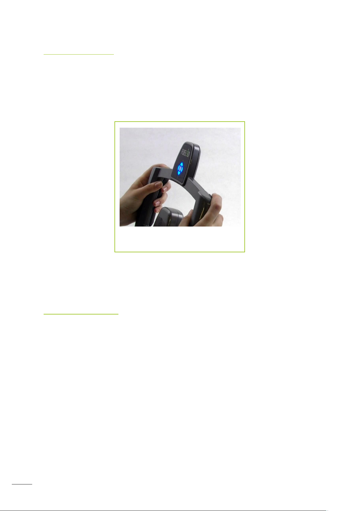
Holding the scanner and using the
trigger buttons
To acquire a scan click on the ‘Viewfinder’ button.
In the Viewfinder, once the target is locked on and highlighted green, you can capture a
scan.
This is accomplished by pressing either one or both of the trigger buttons or by clicking the
‘Capture’ button in the Viewfinder.
Once a scan has been taken it will take 15 seconds for the flashes to cool down before you
can take another scan. This is shown by the progress bar at the bottom of the Viewfinder
image.
Inspecting a scan
Good vs bad data
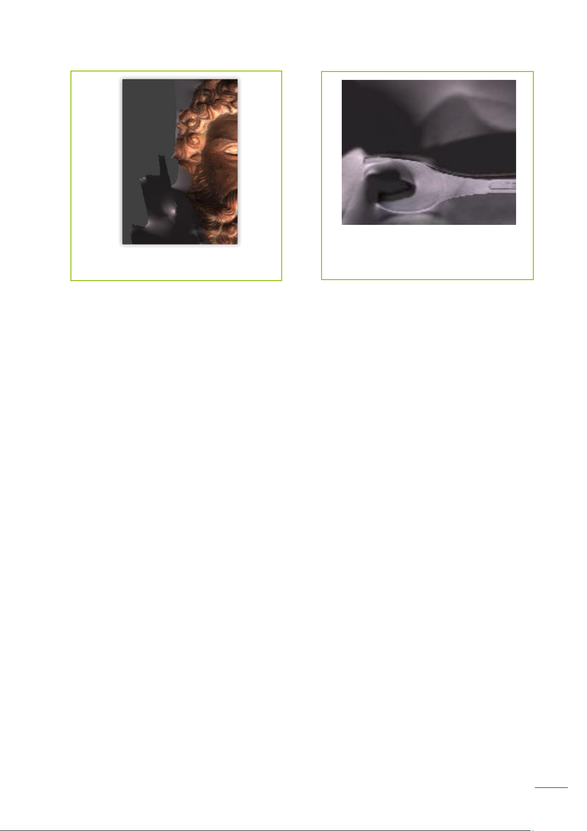
When reviewing a scan you may find some bad data that you wish to remove.
Rotate the scan and locate the data you wish to remove. Bad data will visibly appear
incorrect. It may appear raised, rough or overly smooth and generally will not be
comparable to the subject which was scanned.
Page 31
30
Bad data at the edges of a scan can be
cropped out
Reflective objects, such as this spanner,
may create problems where the surface
reflects the flashes
This bad data is typically found around the edges of your scan or in areas which were not
visible when acquiring the scan.
The mono-color view mode may help you identify which areas are bad.
This data may be removed using the cropping tool.
Spotting movement and lighting interference in your scans
Movement within scans can generate bad data. For example, you may see a ‘noisy’ scan
occasionally where the surface of scan will appear rough when it should be smooth. This
‘noise’ can be attributed to movement either on the part of the operator of the scanner or
the subject being scanned.
This can be solved by ensuring your subject and the operator remain still. It may be best to
retake the scan.
Lighting interference can cause large spikes in the 3D model, or cuts through the data. This
can be caused by background lighting, shiny or reflective objects that may be present in the
scan area.
Page 32
31
Reprocessing a scan
All your image datasets are stored within the Fuel3D Studio system. This means that it is
possible to reprocess scans that you have previously taken.
As the underlying architecture changes over time you may achieve better results
reprocessing a scan using the inbuilt Studio processing engine.
Studio also offers the opportunity to reprocess a scan using a specific algorithm that is
available on the Fuel3D Cloud.
Connecting to the Fuel3D Cloud Service
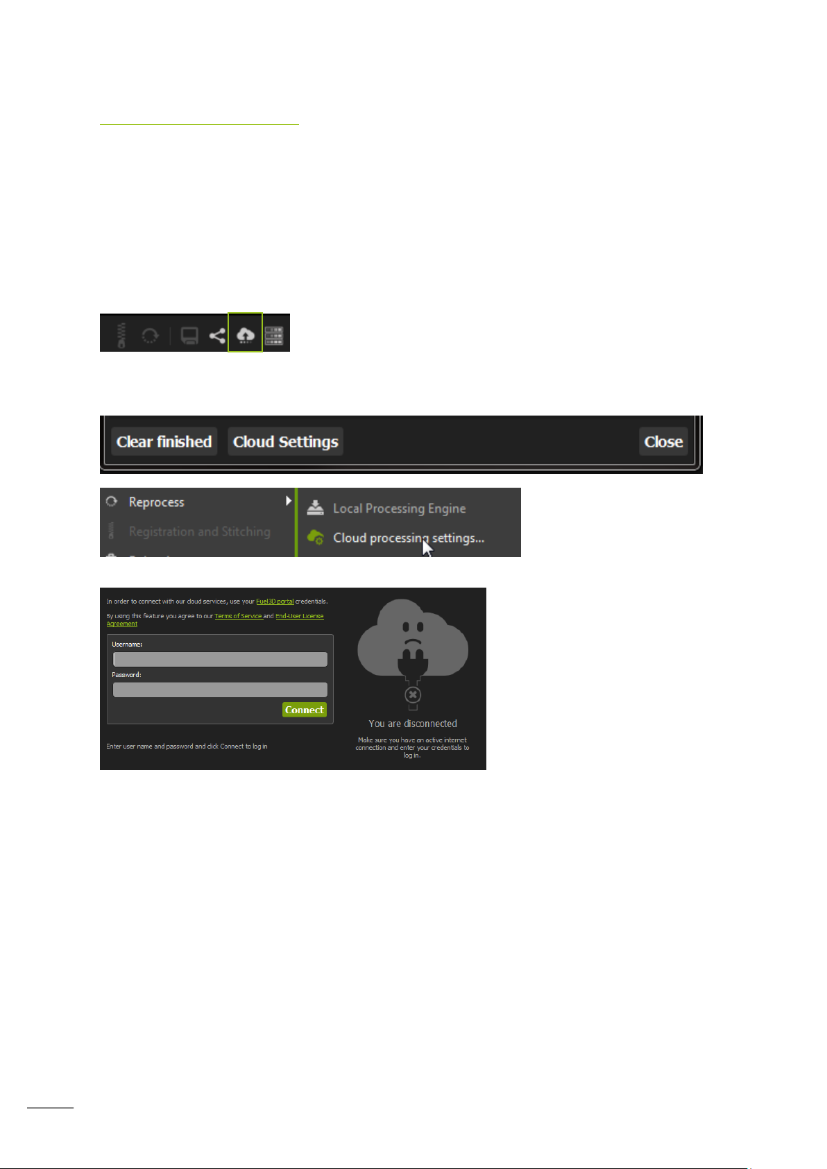
Select the ‘cloud processing progress’ button from the lower
menu selection.
This will open the Cloud Processing Tasks dialog. Select the ‘Cloud Settings’ button which
will open the Cloud settings associated with Studio.
Or you can right click a scan
and select ‘Reprocess’ ->
‘Cloud Processing Settings’
If you have not previously signed
in to cloud settings the
authentication page will appear.
Here you need to enter the
username and password that you
have associated with the fuel3d.com portal. This will then
authenticate access to the cloud
service as well as generate your
processing limit.
The next page displays the engines you have available and the number of scans you can
process.
To process a scan using the cloud algorithm you must right click a scan and then hover over
‘Reprocess’ which will then display a list of available cloud processing engines.
Page 33
32
Adjusting the Lighting
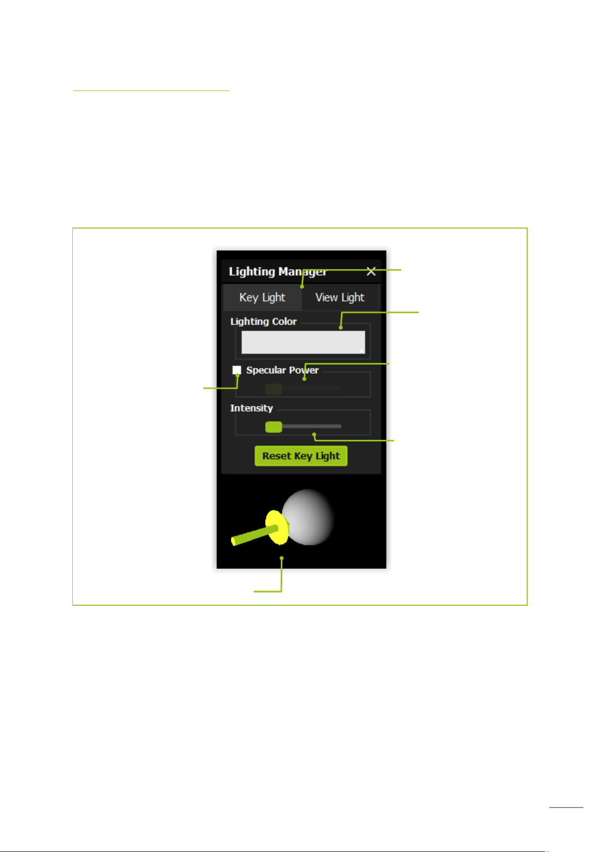
Lighting gimbal
Lighting selection tabs
Dominate
lighting color
Light intensity
Specular intensity
Enable/disable
specular power
It is possible to open the lighting control panel by selecting the lighting button on the
toolbar.
On this window you can edit both of the 3D viewer illumination sources.
The key light affects the directional light which can be controlled with the lighting gimbal.
The view light affects the ambient light which illuminates the whole model.
Page 34
33
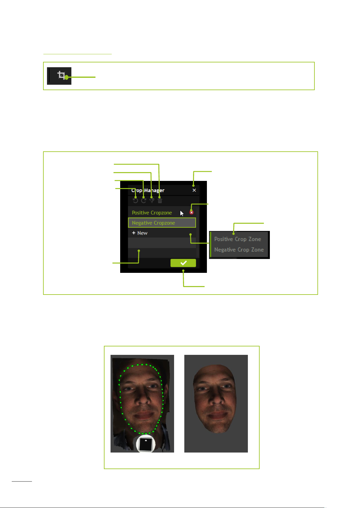
Cropping a scan
Select the cropping button to open the crop interface
Cropping a scan
Cancel cropping mode,
discard changes
Delete crop zone
Remove all cropzones
Erase node mode
Redo
Undo
Create a new
crop zone
Confirm selected crop
List of crop zones
Cropping allows you to place points on your scan to select the area you wish to keep or
remove.
You can place a point by clicking a position on your scan. This creates a node. At least three
nodes are required to create an area that can then be accepted as a crop, however it is
recommended to select more depending on what you are cropping.
The more node points you have the less sharp the edges of the scan will appear; this is
helpful when cropping something round, such as a face, as it allows you to keep the shape
of the face.
Page 35
34
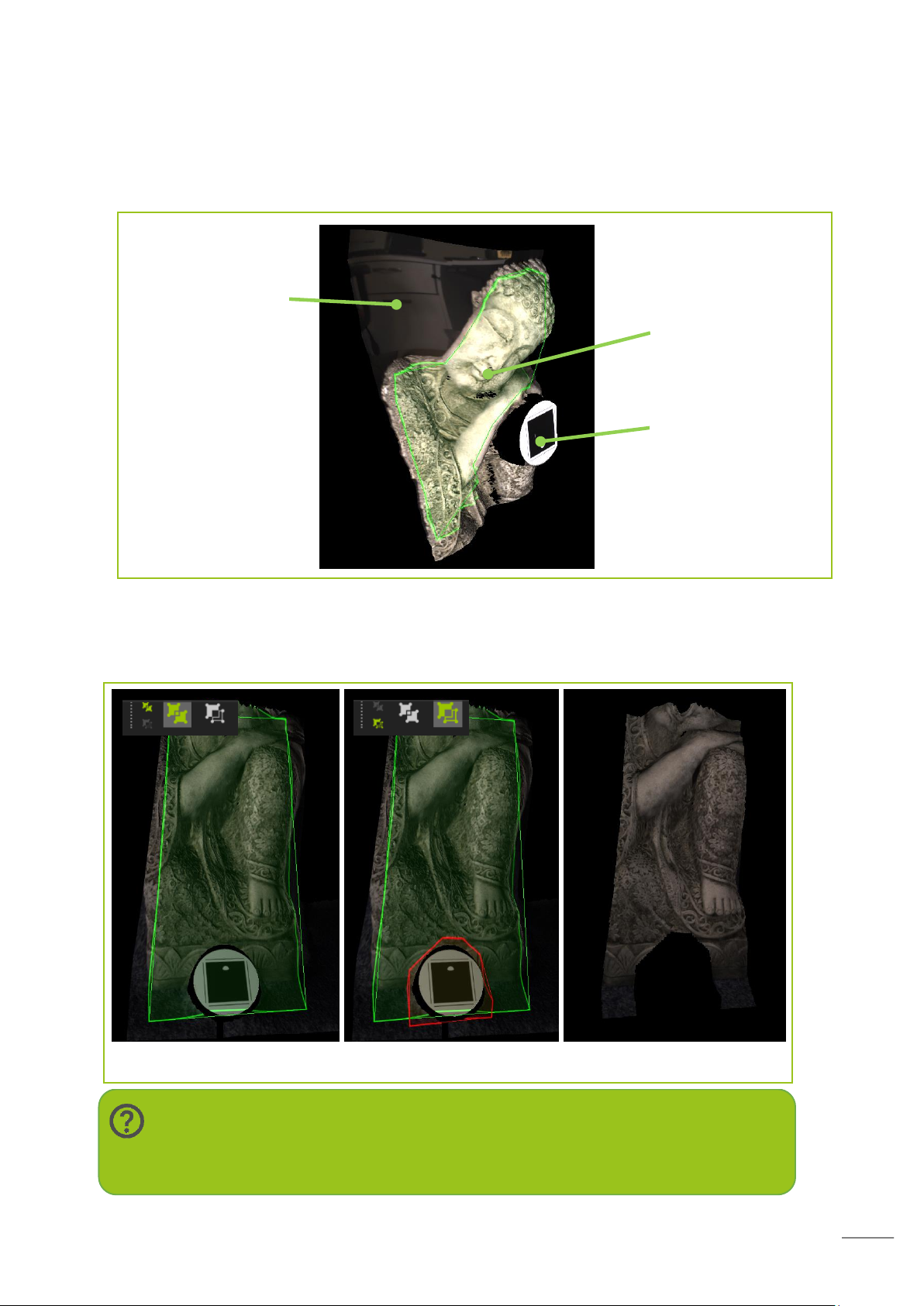
Cropping allows you to place points on your scan to select the area you wish to keep. The
Note:
Don’t worry, your original scan data is saved and a crop can always be
undone, even after the software is closed.
Positive Select Negative Select Resultant
Remove any
geometry that
looks pulled or
distorted
Keep data
Target excluded
from the
selection
image below clearly illustrates what’s good and bad data. You need to remove the data that
looks pulled or stretched, in order to clearly see the pulled data put the scan into mono
mode.
Positive and Negative Crop Zones
It is possible to create multiple crop zones shown as positive (green) and negative (red).
Positive zones are what you wish to keep and negative are specific areas within a crop you
wish to remove. You must always create a positive zone before a negative.
Page 36
35
Exporting a scan
Your scan can be exported in three different file-types and there is also the option of two
different uploads:
STL: this will export your model without any color data. This can be useful if
you’re sending your model to a non-color 3D printer or for use in other 3D
modelling software applications.
PLY: this will export your model with color. If you select the ‘color’ option it will
export it as one file. The color information is stored per-vertex, therefore if you
lower the polygon count of the model the color texture resolution will also be
reduced.
OBJ: this will export your model with color as with PLY. However, it will export 3
files: object, material and bitmap files. The bitmap is overlaid on top of the
model and so lowering the polygon count will not deteriorate the resolution of
the color texture.
Publish with F3D: This will enable you to share your scan with the Fuel3D team
for evaluation and guidance.
Sketchfab: This enables you to quickly upload a scan to the Sketchfab website
www.sketchfab.com once it has been configured.
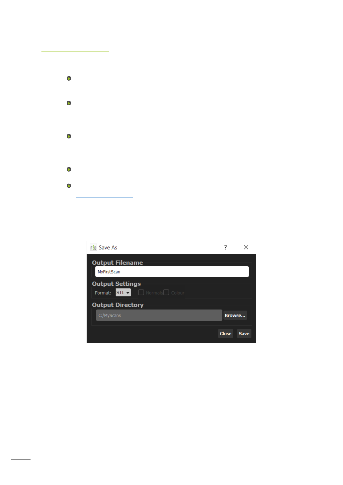
Save As Options
Selecting save will open the save dialog. This will allow you to select the filename to save
as, the output format, whether to save vertex normal (PLY and OBJ only), saving the output
with color data (PLY and OBJ only) and selecting the directory to save your output.
Page 37
36
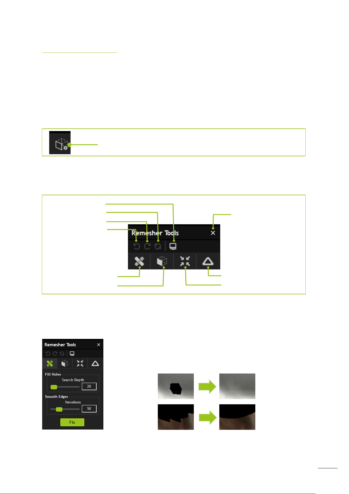
Remeshing a scan
Select the remesher button to enter remeshing mode
Close Remesher tools
Save model
Revert model
Redo action
Undo action
Fix
Volumize
Decimate
Smooth
Remesher mode provides a suite of advanced operations that are available to use on an
individual scan. These include: hole filling, edge smoothing, surface volumization, vertex
decimation, and surface smoothing.
To access Remesher you are required to be using either Plus of Advanced versions of
Studio, with Advanced offering the full range of features available.
This will open the Remesher Tools dialog.
Select one of the options will open the relevant selectors as well as the button to commit the
action.
Fix option
The fix options will fill any holes in your scan and will smooth edges.
Selecting a higher search depth will fill larger holes. Selecting a larger
number of iterations will result in a smoother edge.
Page 38
37
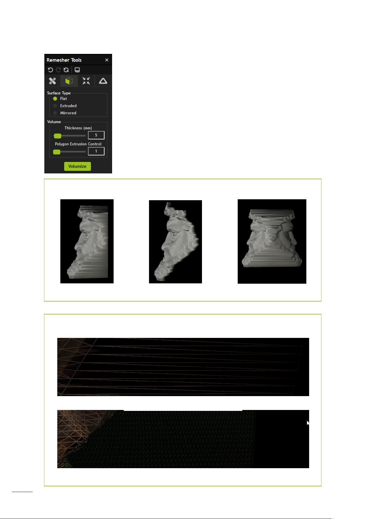
Volumize option
Flat Extruded Mirrored
Volume types
Polygon Extrusion Control
Value of 1
Value of 50
Volumize options allow you to give your scan a thickness, so that it
is ready for 3D printing.
Surface type will select the type of volumization. Thickness is the
depth of the volumized areas. Polygon extrusion control affects the
number of vertices that exist between the top face and bottom face
of your model.
Page 39
38
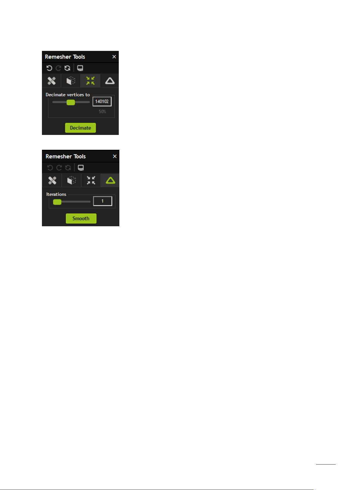
Decimation option
Smooth option
Decimation lowers the number of vertices of the model whilst
attempting to keep the geometry overall similar to the original.
The value in the box is the number of vertices the model will be
decimated to, whilst the percentage below displays the amount
you will decimate as a percentage.
Smoothing attempts to equalize the surface geometry. The
larger the number of iterations the smoother the model will
become.
Saving your scan
The ‘save’ icon will let you output the model you have edited in PLY, OBJ or STL format. OBJ
will, by default, output the model in color.
Page 40
39
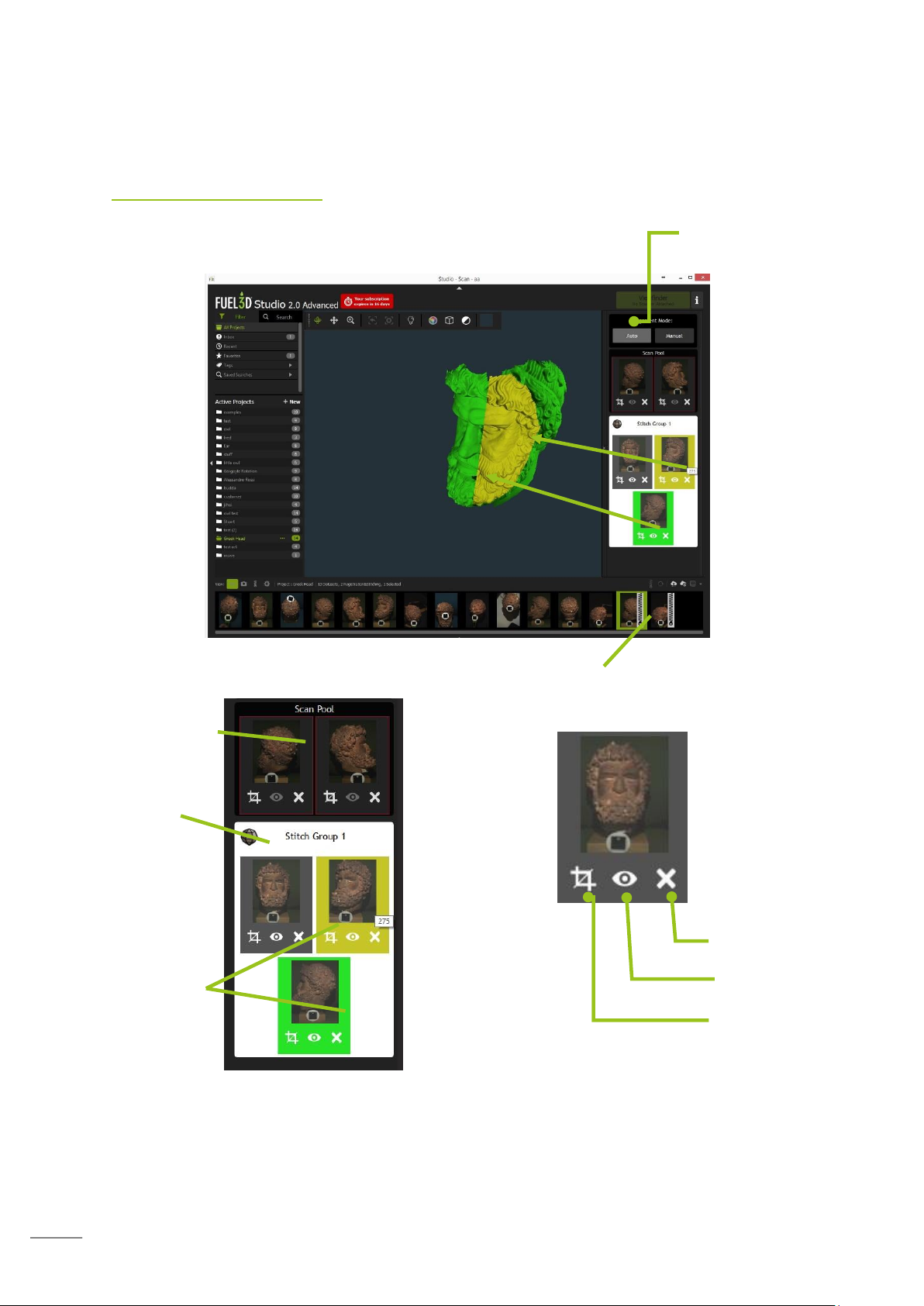
Stitching Overview
Available un-stitched
scans
Active Stitch Group
Select Auto or
Manual Scan
Scans Stitched
together
Stitch Pair see
the above image
for screen display
Delete from Stitch
Group or Scan Pool
Show / Hide
Edit Crop
Interface explained
Page 41

40
Stitching process
Scan
•Take scans in an ordered way
•Disguard any suspect scans and take again
•Ensure you have covered the entire body
and have sufficient overlaps
Crop
•Remove the targets
•Ensure all "pulled" data is removed
•Ensure you have a minimum 20% overlap
Stitch
•Work around the item in
an ordered way
Successful stitching relies primarily on three factors:
Good quality scans
Correctly cropped scans
Ordered alignment of the scans
Cropping
It is generally best to prepare your scan data prior to trying to stitch it together. This speeds
up the stitching process and keeps it simpler.
Select the cropping icon to open the crop interface
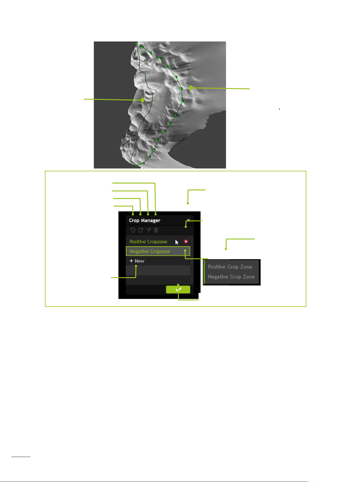
Cropping allows you to place points on your scan to select the area you wish to keep.
See image below which clearly illustrates what’s good and bad data. You need to
remove the data that looks pulled or stretched. In order to clearly see the pulled data
put the scan into monochrome mode.
Page 42
41
Remove the data that
looks pulled and
stretched.
Good data
Cancel cropping mode,
Delete crop zone
Remove all cropzones
Erase node mode
Redo
Undo
Create a new
crop zone
Confirm selected crop
List of crop zones
You can place a point by clicking a position on your scan. This creates a node. At least three
nodes are required to create an area that can then be accepted as a crop but it is
recommended to select more depending on what you are cropping.
The more node points you have, the less sharp the edges of the scan will appear; this
is helpful when cropping something round, such as a face to help keep the shape of
the face.
When stitching multiple scans together there needs to be a minimum of 25% overlap
between scans. This is to ensure you get a successful alignment.
Page 43
42
Ordering
Registration and Stitching
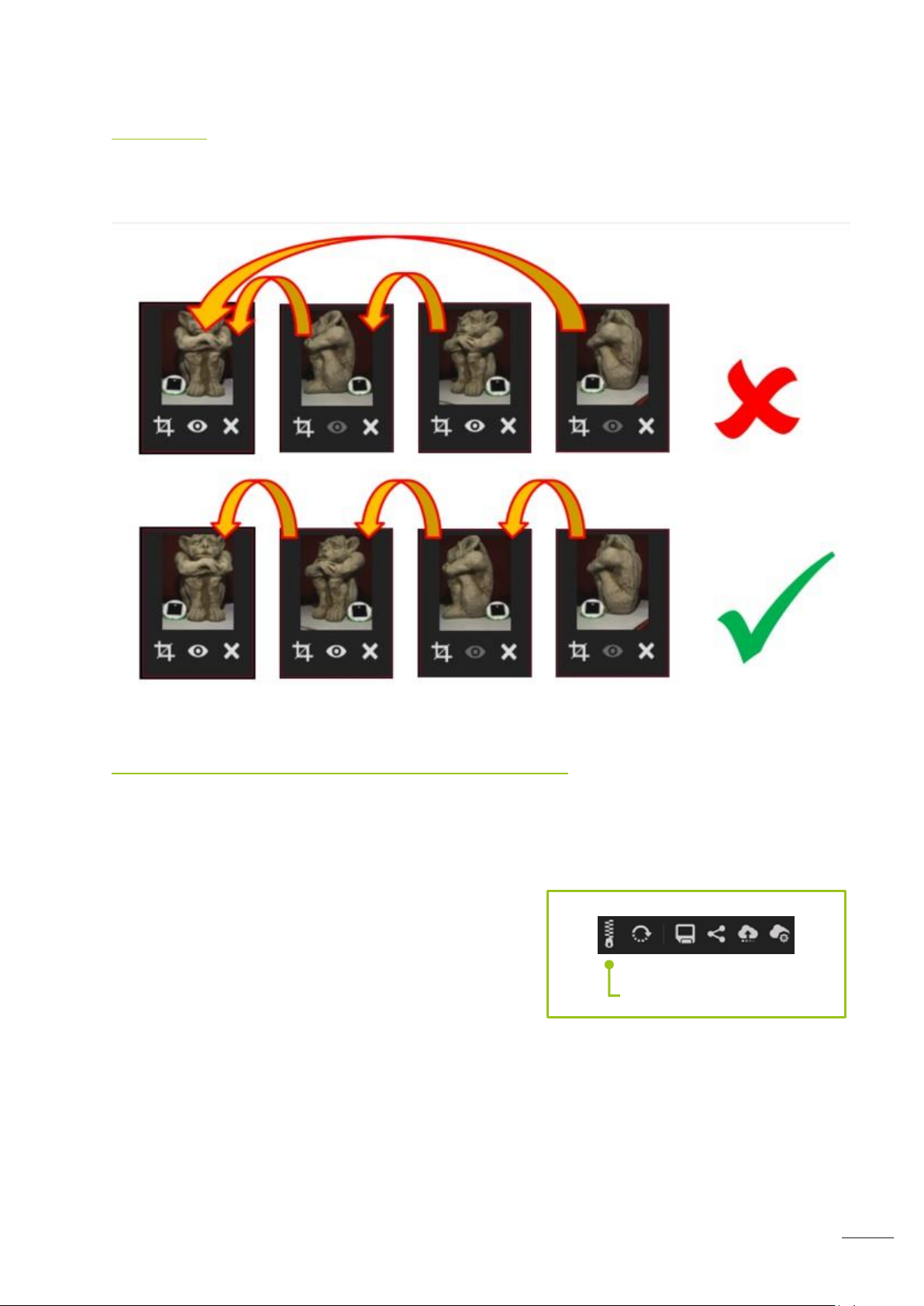
To successfully stitch items together you need to work in an ordered manner working
around the object or person. We recommend starting with two items. Stitch them, add
another item to the stitch set, stitch this and continue.
Creating a Registration and Stitching item
To create a registration and stitching (R&S) item you need at least two scans selected.
Choose and load the first scan into the viewer and then select a scan you wish to join to it
by holding down Ctrl and clicking it. Both will highlight, then either drag the selected items
into the graphics window or click the R&S icon (illustrated below).
You will then be prompted to name the stitching item.
The scan pool will now appear on the right of the
interface. At this time the items are not joined.
You can add additional items by dragging them into the
graphics area.
You will see the stitched item in the scan manger highlighted with a zipper symbol.
Page 44
43
Creating an automatic stitch
Note:
You can use the trim icon to adjust the trimming of the scans during stitching
Note:
When selecting areas to use for alignment, choose areas with consistent detail.
Ensure the Auto mode is selected, then in the stich interface drag and
drop one scan onto the other. The system will process the scans and
“roughly align them” before creating a stitch group. To add to this
stitch group simply select another scan and drag and drop it onto the
next logical scan.
Simply work around the item stitching together the scans. If a scan fails to align correctly
check there is sufficient overlap and there is not any surplus geometry.
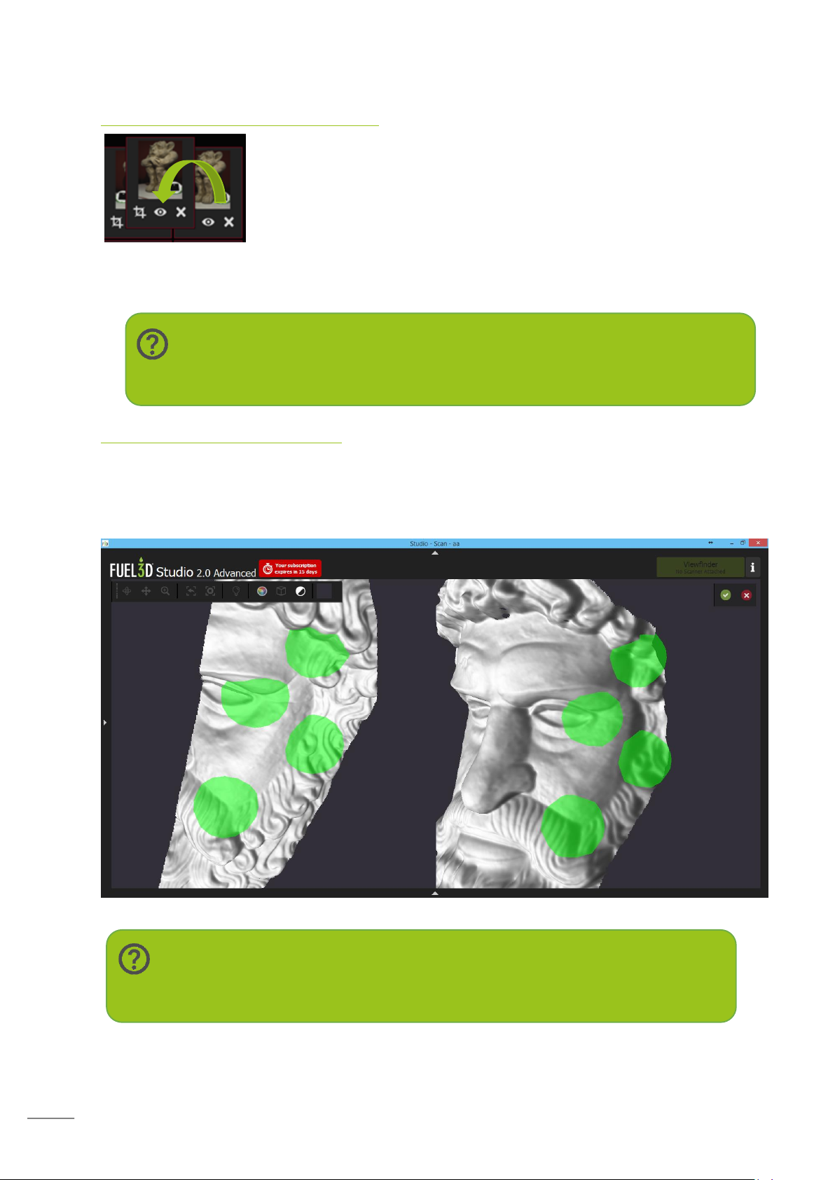
Creating a manual stitch
If automatic stitching does not give the results you require you can switch to manual
stitching. This still requires you to drag and drop the scans over each other but will then
present the user with both the selected scans. It is then left to the user to select matching
areas on both scans. A minimum if three areas are required but we recommend four.
Page 45
44
Completing the stitch
Once you are happy with the alignment of the stitch group and you have all the items you
wish to stitch together it is recommended you review the data then adjust any trims that
have disconnected data.
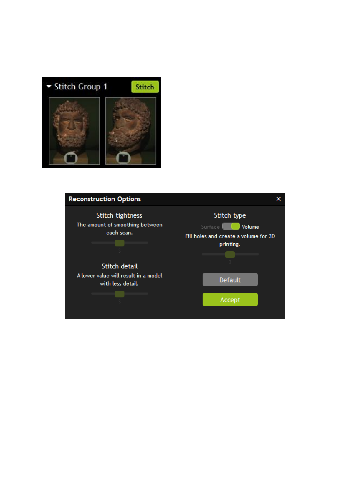
Choose the stitch icon to commit the stitch. This
will begin the fine refinement processing of the
stitch and you will see the scans jump into a
more accurate alignment.
Once the fine alignment is complete you will then
be asked how you wish to complete the stitch
using the reconstruction options.
These reconstruction options are selectable via the dialog box.
Page 46
45
Stitch tightness
Stitch Tightness 5
Stitch Tightness 3
Stitch Tightness 1
Stitch detail 1
Stitch detail 3
Stitch detail 5
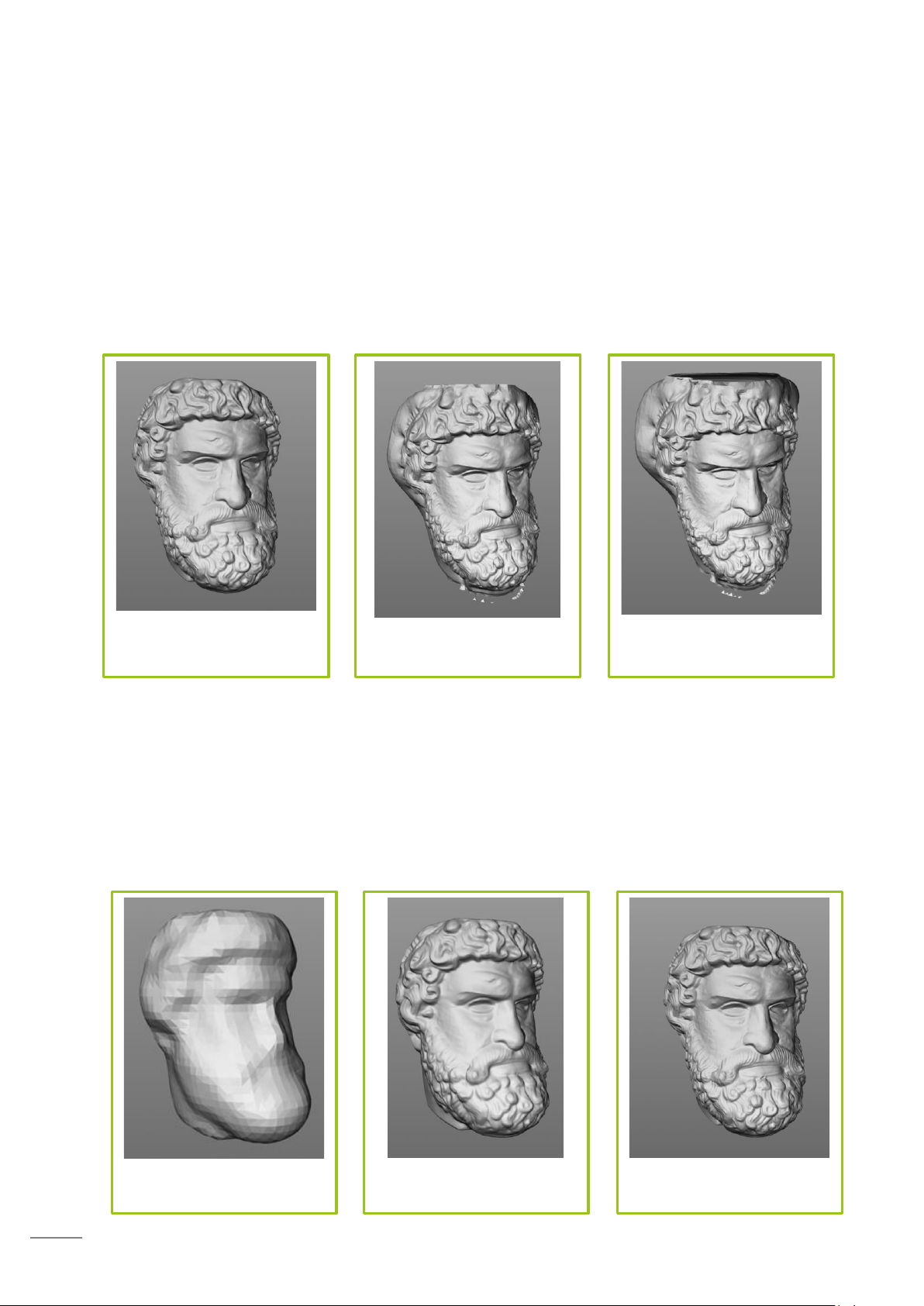
This affects the smoothness of the overlaps between each scan. It also has an effect on the
volumization. A lower value will result in a volumization that displays closer in appearance to
the original alignment.
Scarring appears less pronounced with a lower value.
A higher value causes the volumization to appear larger. In the cases below, at 0.5 and 1,
anomalies have appeared across the model.
Stitch Detail
The depth to which the model is analysed and recreated. A lower detail value will result in a
less detailed reconstruction.
Increasing the value also increases processing time.
A lower value can lower the appearance of scarring and also the size of the output model.
Page 47
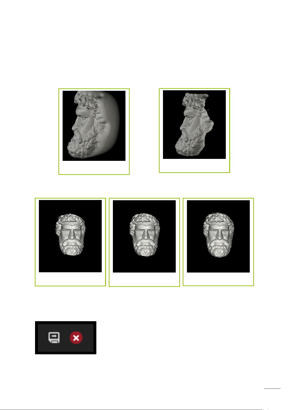
46
Stitch Type
Volumization on
Volumization off
Trim value 1
Trim value 3
Trim value 5
It is possible to stitch the model as both a surface or a volume.
If you choose to stitch your scans as a surface the option for stitch trimming will be
available.
Lowering this value will mean more of the model is trimmed away whilst increasing it will
mean a decrease to the amount of cutting away occurs on the model.
As you may see, with a higher value some anomalous floating data has appeared above the
scan. The amount of trimming will depend on what type of model you are stitching.
Saving the Stitch
The final operation is to export the stitched data. This can be
saved as .STL, .PLY or .OBJ data. Choosing the floppy disk icon
will save the stitch and the red x icon will abort the stitch.
Page 48
47
Troubleshooting
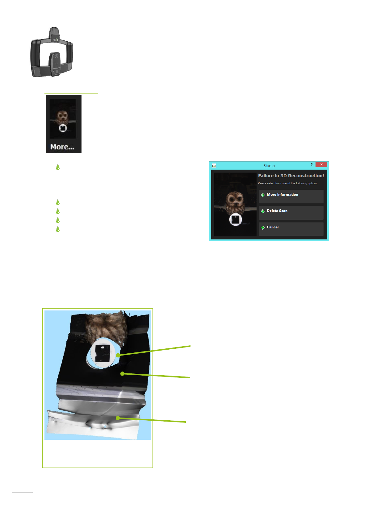
An example of a processed failed
scan
Bad target, note the damage.
Black background absorbs the light.
Here, the white highly reflective desk
reflect the light and cause the strange
peaks and troughs.
Failed Scans
Scans can fail for a number of reasons. The system will highlight failed scans
by putting the word ‘More…’ under the preview image.
If you choose the scan you will then get a dialog that will enable you to
explore why the scan failed or delete the scan.
More information will suggest possible reasons for the scans failure. The
primary reasons for the scan to fail are:
The target cannot be found, normally this is
due to the angle of the target It may be
slightly covered or on the very edge of the
scan.
The scanner moved during capture.
Dirt on the lenses.
A flash was covered during scanning.
Lighting was incorrect or there was a
reflective item in the scan.
If you have a failed scan you are given the options to delete it and try again. You may also
upload the failure report to Fuel3D, there are two reports but the full report includes the
scan data. These reports help the Fuel3D support engineers to diagnose why the scan
failed.
Sometimes the system will also offer to build the file but it may contain errors.
Page 49
48
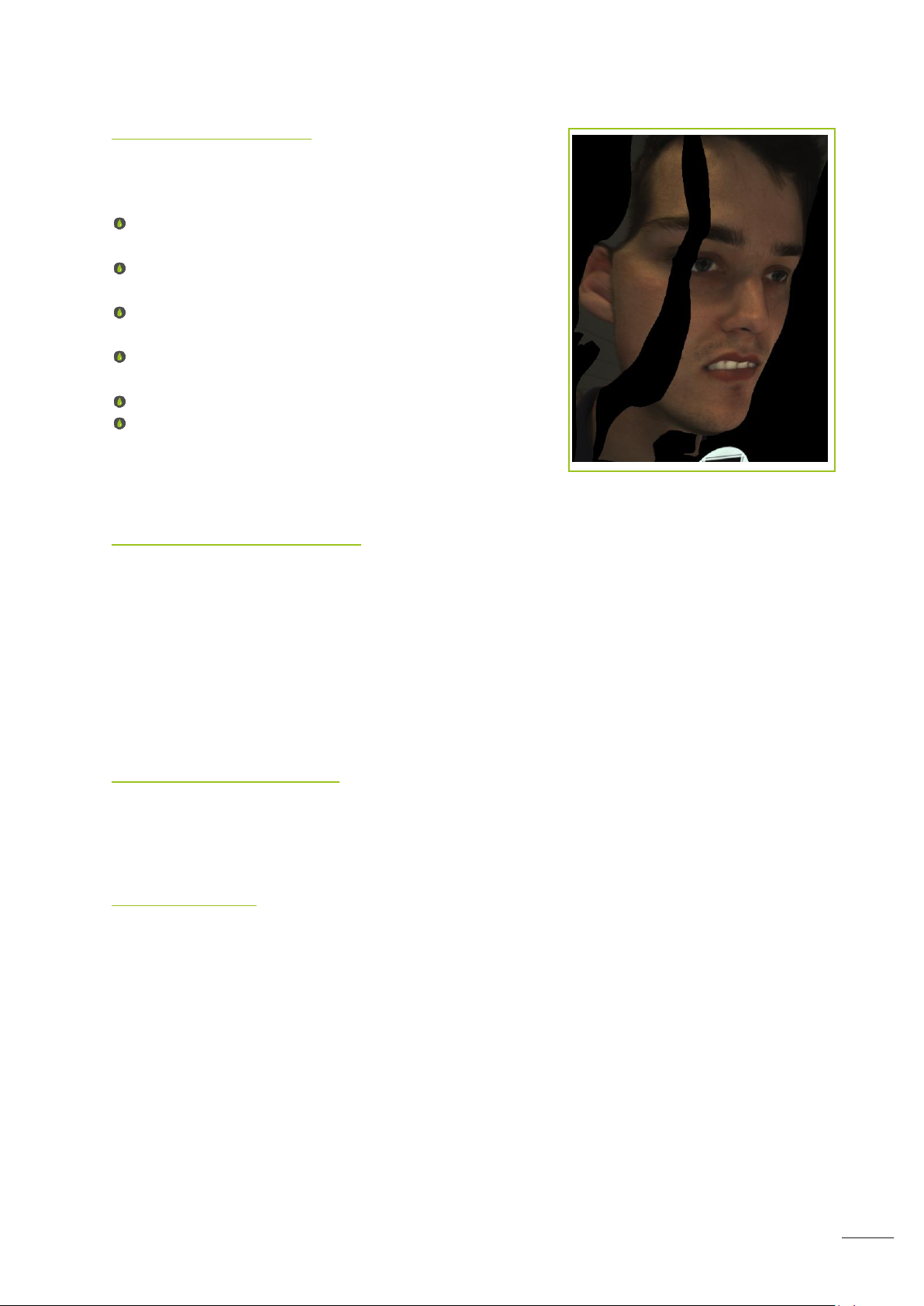
Cuts in your scans
Cuts in your scans can be caused by a number of issues:
If there is a shiny or reflective object in the scan, such
as jewelry.
If there is bright lighting in the background, such as a
light or bright window.
If the subject is moving quickly whilst the scan is being
taken.
Very dark objects which the scanner struggles to
illuminate.
Bright objects which may reflect too much light.
Very shiney hair can reflect the light.
Target troubleshooting
It is important to take care of your targets. They should be stored safely when not in use so
that they are not bent or damaged.
Bending the targets will cause processing to fail and the viewfinder will be unable to track
the target correctly.
Do not replicate the targets as this can cause issues with processing and may result in an
inaccurately scaled model. You can order new targets from the Fuel3D website.
Inaccurate geometry
Inaccurate geometry is most likely the result of selecting an inappropriate subject. Please
see the subject selection section to help guide you with selecting a suitable subject.
Workarounds
Workarounds may help scan subjects which may otherwise not scan correctly.
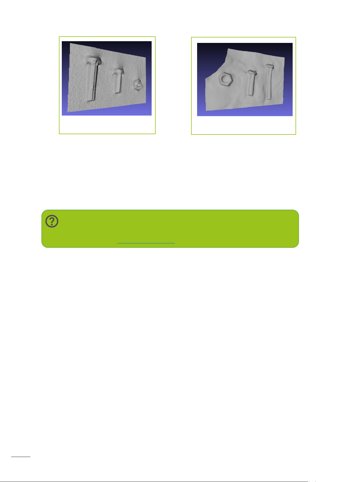
You may embed your subject in kinetic sand to leave an imprint. This imprint can then be
scanned and cropped to produce a replica of the subject, much like making a cast.
Page 50
49
Note:
For a full list of workarounds, instructions and issue troubleshooting please
visit our FAQ at: fuel3D.zendesk.com.
Screw scan outputs
Screw scan outputs by imprinting
in the sand
You may also use non-permanent texture spray to coat your object with and then complete
your scan. This spray will help to cover reflective surfaces which will improve the scan
outputs.
Talcum powder may be used when the subject has very dark hair to improve the scan
quality.
 Loading...