

Page 1
MODEL: FM20AMG (Modular)
PLEASE RETAIN THIS MANUAL FOR FUTURE REFERENCE.
Do not operate the grill under unprotected combustible construction. Use only in well
•
ventilated areas. Do not use in buildings, garages, sheds, breezeways or other such
enclosed areas. This unit is for outdoor use only.
This outdoor cooking gas appliance is not intended to be installed in or on recreational
•
vehicles and/or boats.
WARNING:
1. Do not store or use gasoline, or other
ammable liquids or vapors in the
vicinity of this or any other appliance.
2. An LP cylinder not connected for use
shall not be stored in the vicinity of
this or any other appliance.
DANGER
If you smell gas:
1. Shut off gas to the appliance.
2. Extinguish any open ame.
3. Open lid.
4. If odor continues, keep away from the
appliance and immediately call your
gas supplier or your re department.
FUEGO North America
Roundhouse One
1500 Sansome Street, Suite 100
San Francisco, CA 94111
415.558.7151 (local)
1.888.88.FUEGO (toll free)
www.fuegoliving.com
APR09
1
Page 2

TABLE OF CONTENTS
3 Safety Practices & Precautions
Gas Requirements
6 General
7 LP Gas
8 Leak Testing
9 List of Included Materials
10 Dimensions
Assembly
11 Frame, Handles and Knobs
12 Modular Units
13 Light Unit and End Panels
14 Gas Connections
16 Drawer Installation and Grate Assembly
17 Battery Installation
18 Warming Drawer
19 Optional Charcoal Drawer
20 Utility Unit
21 Counter-Tops
Using the Grill
24 Grilling
25 Infrared Cooking
26 Burner Adjustments
Maintenance
27 Burner
28 Care & Cleaning
29 Cooking Tips
32 Troubleshooting
34 Accessories
35 Warranty
WARNING:
Improper installation, adjustment, alteration, service or maintenance can cause property
damage, injury or death. Read the installation, operating and maintenance instructions
thoroughly before using, installing or servicing this equipment. For outdoor use only.
2
Page 3
IMPORTANT SAFETY NOTICE:
Certain Liquid Propane dealers may ll liquid propane cylinders for use with the grill beyond
cylinder lling capacity. This “Over lling” may create a dangerous condition.
“Over lled” tanks can build up excess pressure. As a safety device, the tank’s pressure relief
valve will vent propane gas vapor to relieve this excess pressure. This vapor is combustible
and therefore can be ignited. To reduce this danger, you should take the following safety
precautions:
1. When you have your tank lled, be sure you tell the supplier to ll it to
no more than 3/4 (75%) of its total capacity.
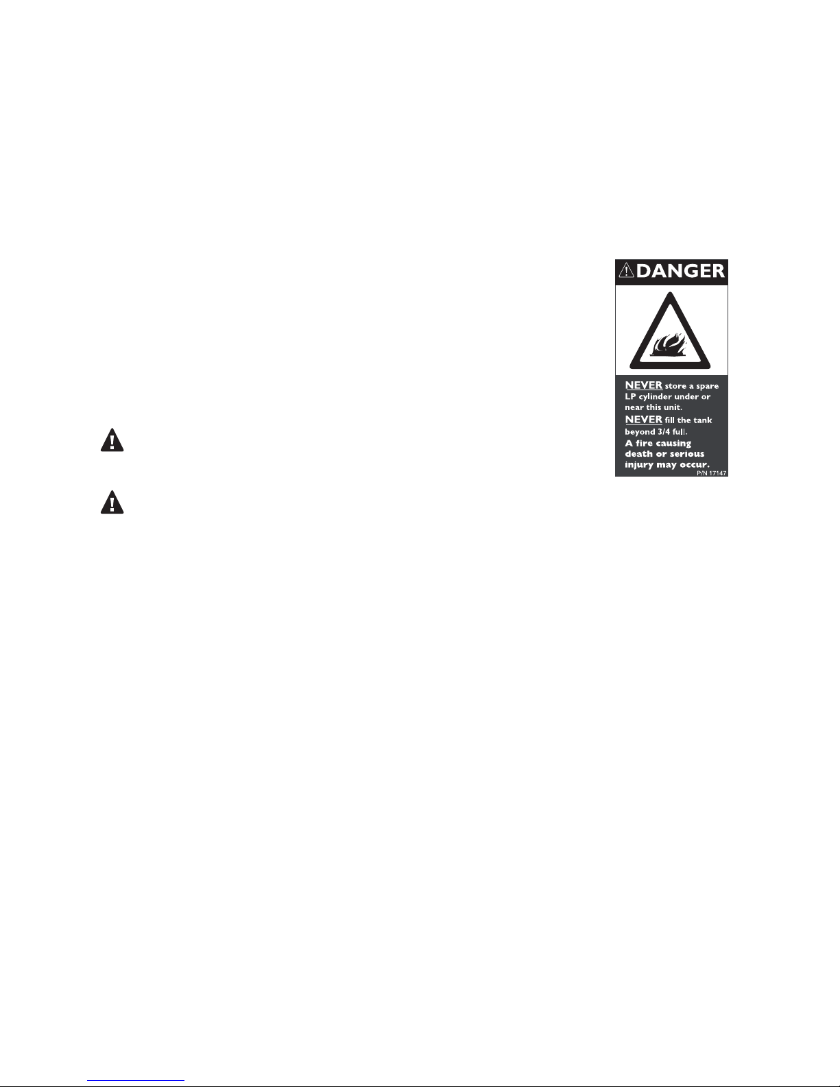
2. If you own or use an extra tank, or have a disconnected tank, you
should NEVER store it near or under the grill/cart unit or heat box,
or near any other ignition or heat source. A metallic sticker with this
warning is attached to the grill to remind you, your family and all
others who may use your BBQ grill of these safety precautions.
Do not remove this sticker.
WARNING:
Do not try lighting this appliance without reading the “LIGHTING
INSTRUCTIONS” section of this manual. This grill is for outdoor use only.
SAFETY PRACTICES & PRECAUTIONS
WARNING:
Push and hold the igniter button, turn the selected burner knob to “high”. If burner does
not light in 4 to 5 seconds turn knob “OFF” and wait 5 minutes before trying again for any
accumulated gas to dissipate.
Begin by ensuring proper installation and servicing. Follow the installation instructions
•
provided with this product. Have your grill installed by a quali ed technician. Have the
installer show you where the gas supply shutoff valve is located so that you know where
to shut off the gas to the grill. If you smell gas, your installer has not done a proper job of
checking for leaks. If the connections are not perfectly sealed, you can have a small leak
and therefore a faint gas smell. Finding a leak is not a “do-it-yourself” procedure. Some
leaks can only be found with the burner control in the “ON” position and this must be
done by a quali ed technician.
Children should not be left alone or unattended in an area where the grill is being used.
•
Never allow them to sit, stand or play on or around the grill at any time. When in use,
portions of the grill get hot enough to cause severe burns.
Do not store items of interest to children around or below the grill. Never allow children to
•
crawl inside the storage drawer.
Never let clothing, pot holders or other ammable materials come in contact with or get
•
too close to any grate, burner or hot surface until it has cooled. Fabric may ignite and
result in personal injury.
Do not heat unopened food containers as a build-up of pressure may cause the container
•
to burst.
Always use a covered hand when opening the grill lid and only do so slowly to allow heat
•
and steam to escape.
3
Page 4
SAFETY PRACTICES & PRECAUTIONS
Never lean over an open grill. When lighting a burner, always pay close attention to what
•
you are doing. Be certain you are pushing the ignition button when you attempt to light
the grill.
When using the grill, do not touch the grill burner grate or immediate surrounding area as
•
these areas become extremely hot and could cause burns.
Grease is ammable. Let hot grease cool before attempting to handle it. Avoid letting
•
grease deposits collect in the drip pan. Clean often.
Do not use aluminum foil to line drip pans or grill racks. This can severely upset
•
combustion air ow or trap excessive heat in the control area. The result of this can be
melted knobs or damaged ignition components.
For personal safety, wear proper apparel. Loose tting garments or sleeves should never be
worn while using this appliance. Some synthetic fabrics are highly ammable and should not
be worn while cooking. Only certain types of glass, heat-proof glass ceramic, earthenware or
other glazed utensils are suitable for grill use. These types of materials may break with sudden
temperature changes. Use only on low or medium heat settings according to the manufacturer’s
directions.
WARNING:
Spiders and insects can nest in the burners of this and any other grill, and cause the gas to ow
from the front of the burner. This is a very dangerous condition which can cause a re to occur
behind the valve panel, thereby damaging the grill components and making it unsafe to operate.
WARNING:
Keep the area surrounding the grill free from combustible materials, trash or combustible uids
and vapors such as gasoline or charcoal lighter uid. Do not obstruct the ow of combustion or
ventilation air.
WARNING:
Never use the grill in windy conditions. If located in a consistently windy area (oceanfront,
mountaintop, etc.) a wind break will be required. Always adhere to the speci ed clearances
listed on page 10.
4
Page 5

Clean the grill with caution. Avoid steam burns; do not use a wet sponge or cloth to clean
•
the grill while it is hot. Some cleaners produce noxious fumes or can ignite if applied to a
hot surface.
Be sure all grill controls are turned off and the grill is cool before using any type of aerosol
•
cleaner on or around the grill. The chemical that produces the spraying action could, in
the presence of heat, ignite or cause metal parts to corrode.
Do not use the grill for cooking excessively fatty meats or products which promote
•
are-ups.
Never grill without the residue pan in place. Without it, hot grease could leak downward
•
and produce a re or explosion hazard.
If grill is stored indoors, ensure that it is cool. If LP, the cylinder must be unhooked and the
•
LP cylinder stored outside in a well ventilated area, out of reach of children.
Keep any electrical supply cord away from the heated areas of the grill and water.
•
Never use a dented or rusty LP tank. Keep the ventilation openings of the cylinder
•
enclosure free and clear from debris.
Use only dry potholders; moist or damp potholders on hot surfaces may cause burns from
•
steam. Do not use a towel or bulky cloth in place of potholders. Do not let potholders
touch hot portions of the grill or burner grate.
SAFETY PRACTICES & PRECAUTIONS
Teak countertops not recommended for use in food preparation.
•
CALIFORNIA PROPOSITION 65-WARNING: The Burning of gas cooking fuel generates
•
some by-products which are on the list of substances which are known by the State of
California to cause cancer or reproductive harm. California law requires businesses to
warn customers of potential exposure to such substances. To minimize exposure to these
substances always operate this unit according to the Use and Care Manual, ensuring you
provide good ventilation when cooking with gas.
5
Page 6

GAS REQUIREMENTS: GENERAL
Verify the type of gas supply to be used, either natural or LP, and make sure the marking on the
appliance rating plate agrees with that of the supply. The rating plate is located on the inside back
wall of the grill. Never connect an unregulated gas line to the appliance.
An installer supplied gas shutoff valve must be installed in an easily accessible location. All installer
supplied parts must conform to local codes, or in the absence of local codes, with the National
Electrical Code, ANSI/NFPA 70 or the Canadian Fuel Gas Code, ANSI Z223.1 or CAN/CGA-B149.2
Propane Installation Code.
All pipe sealants must be an approved type and resistant to the actions of LP gases. Never use
pipe sealant on are ttings. All gas connections should be made by a quali ed technician and in
accordance with local codes and ordinances. In the absence of local codes, the installation must
comply with the national fuel gas code ANSI Z223.1. Gas conversion kits are available from your
dealer. When ordering gas conversion kits, have the model number and the type of gas (natural or
LP) from your grill.
GAS CONSUMPTION ON HIGH:
Gas Unit - 18,500 Btu/hr
Infrared Unit - 18,500 Btu/hr
Cooking Unit - 12,000 Btu/hr (each burner)
The appliance and its individual shutoff valve must be disconnected from the gas supply piping
system during any pressure testing of that system at test pressures in excess of 1/2 PSIG (3.5
kPa.) The appliance must be isolated from the gas supply piping system by closing its individual
manual shutoff valve during any pressure testing of the gas supply piping system at test pressures
equal to or less than 1/2 PSIG (3.5 kPa.). The installation of this appliance must conform with local
codes or, in the absence of local codes, with the national fuel gas code, ANSI Z223.1. Installation in
Canada must be in accordance with the Standard CAN/CGA-B149.2 Propane Installation Code and
local codes.
NATURAL GAS HOOK UP (standard equipped):
Out of the box the Modular comes ori ced for use with NG (natural gas) only. If you wish to use
LP gas you will need to purchase a conversion kit.
(This type of connection should be performed by a certi ed or licensed technician only.)
Connection: 1/2” NPT male adapter. Operating pressure: 4.0” W.C. Supply pressure: 5” to 14” water
column. If in excess of 14” W.C. a step down regulator is required. Check with your local gas utility
company or with local codes for instructions on installing gas supply lines. Be sure to check on
type and size of run, and how deep to bury the line. If the gas line is too small, the grill will not
function properly. Any joint sealant used must be an approved type and be resistive to the actions
of natural gases.
Use threading compound on male threads only. Use a pipe wrench to hold the grill inlet pipe to
avoid shifting any internal gas lines of the grill and install 90 degree elbow. Do not forget to place
the installer supplied gas valve in an accessible location.
LP GAS HOOK UP FOR TYPE 1 OR QCC1 REGULATOR (Optional Accessory FA20ALP) SOLD
SEPARATELY:
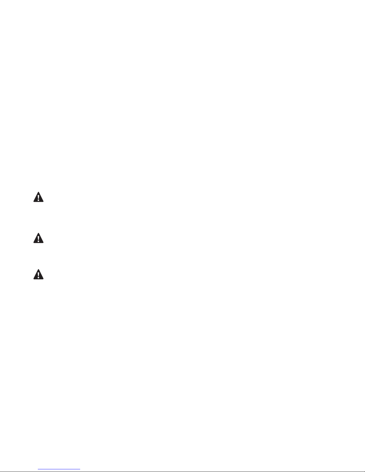
An optional LP conversion kit is available which includes replacement ori ces, a high capacity
hose and regulator assembly for connection to a standard 20lb. LP cylinder (Type 1) Fig.01. The LP
tank is not included. LP hose with a quick disconnect and ttings are included. Operating pressure:
10” W.C. The ori ces included with the Modular are for use with NG only and must be changed to
LP ori ces.
6
Page 7
Locate the brass nozzle inside each burner unit with pre-
TYPE 1
LP TANK
FA20ALP
LP HOSE
WITH
REGULATOR
Installation must conform with local
codes or with the National Fuel Gas
Code ANSI Z223.1 or the CAN/CGAB149.2 Propane Installation Code
attached NG gas ori ce. The ori ce is the small screw on the
end of the nozzle with a hole in the center. Unscrew the NG
gas ori ce by turning counter-clockwise and replace with LP
ori ce. Use the 1.30mm ori ces for each gas and infrared unit
and the 1.05mm ori ces for the two cook unit burners. The
LP ori ce has a smaller hole in the center to keep the ow of
LP gas consistent. You will need to replace the ori ces in each
unit (Fig. 02)
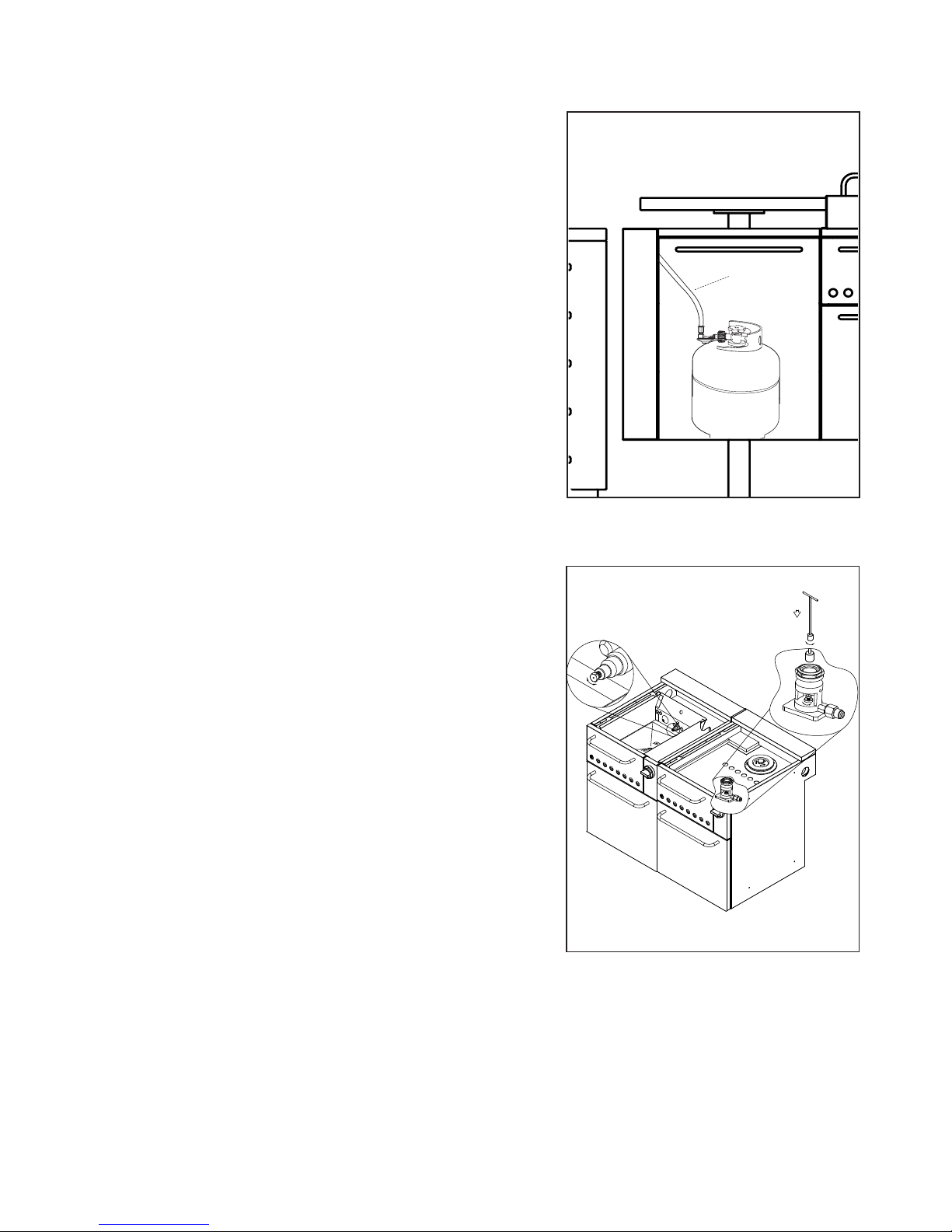
To connect the LP regulator and hose assembly to the tank/
valve assembly, rst make sure the main valve on the tank
is completely closed. Although the ow of gas is stopped
when the Type 1 system is disconnected as part of its safety
feature, you should always turn off the LP tank main valve
(FIG. 02) after each use and during transport of the tank or
unit. Insert the regulator inlet into the tank valve and turn the
black coupler clockwise until the coupler tightens up. Do not
overtighten the coupler. Turn the main tank valve on and turn
the burner control valves on the unit to “HIGH” position for
about 20 seconds to allow the air in the system to purge. Turn
valves off and wait 5 minutes before attempting to light the
burners.
GAS REQUIREMENTS: LP GAS
Fig. 01 LP Gas
To disconnect the coupler, rst make sure the main tank valve
is turned off. Grasp the coupler and turn counter-clockwise.
The inlet will then disengage. Remove the inlet from the tank
valve opening if it has not already done so when disengaging.
Your local LP lling station should be equipped with the proper
equipment to ll your tank.
LP TANK REQUIREMENTS:
A dented or rusty LP tank may be hazardous and should be
checked by your LP supplier. Never use a cylinder with a
damaged valve. Always check for leaks after every LP tank
change. The LP gas cylinder must be constructed and marked
in accordance with the speci cations for LP gas cylinders of
the U.S. Department of Transportation (DOT or CAN/CSAB339) and designed for use with a Type 1 system only. Do not
change the regulator and hose assembly from that supplied
with the unit or attempt to use a Type 1 equipped regulator
and hose assembly with a standard 510 POL tank/valve
assembly. The cylinder must be provided with a shutoff valve
terminating in an LP gas supply cylinder valve outlet speci ed,
as applicable, for connection Type 1. If the appliance is stored
indoors, the cylinder must be disconnected and removed from
the appliance. Cylinders must be stored outdoors in a wellventilated area out of the reach of children.
Fig. 02 Ori ce Replacement
NOTE: Do not use LP ori ces with natural
gas or NG ori ces with an LP gas tank.
NOTE: When an LP unit is directly attached into an LP house
system, the step down regulator MUST be used to reduce the
supply pressure to a max. 14" W.C. and min. 11" W.C. to the grill
regulator.
7
Page 8
GAS REQUIREMENTS: LEAK TESTING
LP TANK
LEAK TEST
POINTS
CHECK HOSE
FOR SIGNS OF
ABRASIONS,
CRACKS OR
LEAKS
GENERAL:
Although all gas connections on the grill are leak tested at the factory prior to shipment, a complete gas
tightness check must be performed at the installation site due to possible mishandling in shipment, or
excessive pressure unknowingly being applied to the unit. Periodically check the whole system for leaks, or
immediately if the smell of gas is detected.
BEFORE TESTING:
Do not smoke while leak testing. Extinguish all open ames. Never leak test with an open ame. Make a soap
solution of one part liquid detergent and one part water. You will need a spray bottle, brush, or rag to apply
the solution to the ttings. For LP units, check with a full cylinder. Remove the control knobs and battery to
disable accidental ignition. Open the drawer containing LP or natural gas hook up, this is where all tests will be
performed.
TO TEST:
Make sure all control valves are in the “OFF” position. Turn the gas supply “ON”. Check all connections from
the supply line, or LP cylinder up to and including the manifold pipe assembly. Apply the soap solution around
the connection, valve, tubing and end of the manifold. Soap bubbles will appear where a leak is present. If a
leak is present, immediately turn off gas supply, tighten any leaking connections, turn gas on, and recheck.
Check all the gas connections at the base of the control valves where they screw into the manifold pipe.
If you cannot stop a gas leak, turn off the gas supply and call your local gas utility or the dealer you purchased
the appliance from. Only those parts recommended by the manufacturer should be used on the grill.
Substitution can void the warranty.
WARNING:
Do not use the grill until all connections have been checked and do not leak.
Check all gas supply ttings for leaks before each use. It is handy to keep a spray bottle of soapy water near
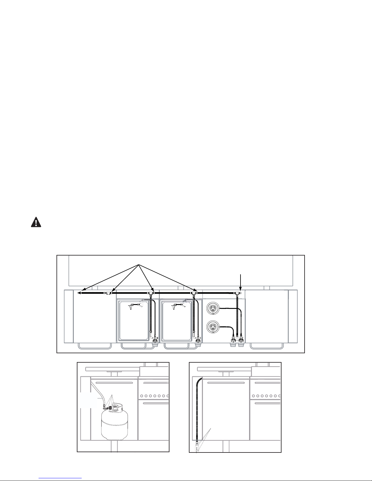
the shutoff valve of the gas supply valve. Spray all the ttings. Bubbles indicate leaks. (FIG. 03 & 04)
Leak Test Points
Termination Cap
to gas
main
Fig. 03 Internal Hoses
8
Fig. 04a LP Gas Fig. 04b Natural Gas
Ł
LEAK TEST
POINTS
NG Main
Page 9
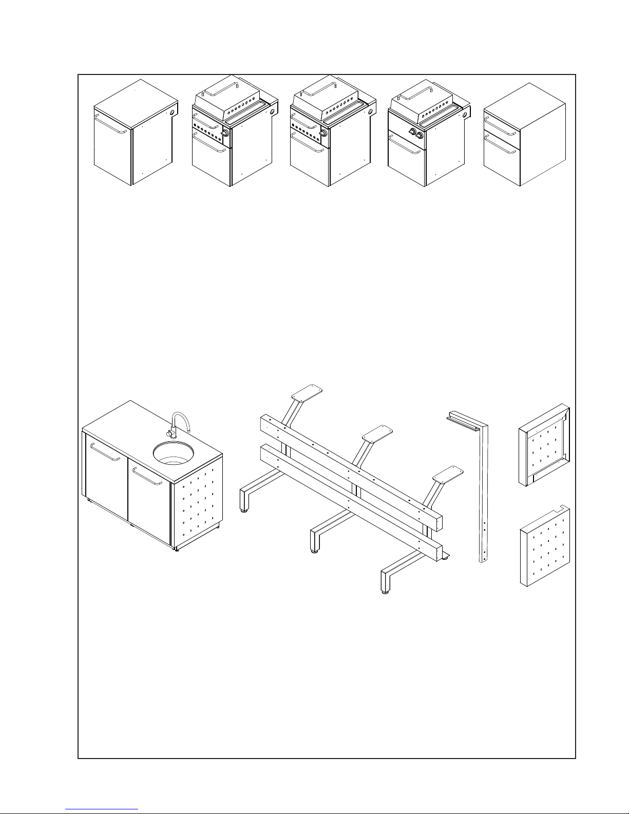
LIST OF INCLUDED MATERIALS
FM20ASU: STORAGE UNIT
1 - Storage Unit Body
1 - Teak Top
1 - LP Tank Holder
1 - Drawer Separator
1 - Handle
1 - NG Hose
2 - M6x12 screws w/spacer
4 - M6x12 screws
FM20AGU: GRILL UNIT
w/ GAS DRAWER
1 - Grill Unit Body
1 - Gas Drawer
1 - Cast Iron Grate Frame
1 - Cast Iron Grate
1 - Residue Tray
1 - Lid
3 - Handles
1 - Metal Gas Hose
1 - Control Knob
1 - AA Battery
6 - M6x12 Screws
w/spacer
4 - M6x12 Screws
1 - M6x12 Screw w/Nut
FM20AIU: INFRARED UNIT
w/ INFRARED DRAWER
1 - Grill Unit Body
1 - Infrared Drawer
1 - Cast Iron Grate Frame
1 - Cast Iron Grate
1 - Residue Tray
1 - Lid
3 - Handles
1 - Metal gas Hose
1 - Control Knob
1 - AA Battery
6 - M6x12 Screws
w/spacer
4 - M6x12 Screws
1 - M6x12 Screw w/Nut
FM20ACU: COOK UNIT
1 - Cook Unit Body
w/ 2 Burners
1 - Cast Iron Grate Frame
2 - Cast Iron Grate
1 - Residue Tray
1 - Lid
2 - Handles
1 - Metal gas Hose
2 - Control Knobs
1 - AA Battery
6 - M6x12 Screws
w/spacer
4 - M6x12 Screws
1 - M6x12 Screw
FM20AWU: WARM UNIT
1 - Warming Unit Body
1 - Slate Top
4 - Dish Covers
2 - Storage Dishes
4 - Cha ng Dishes
2 - Water Dishes
2 - Sterno Holders
1 - Sterno Tray Holder
2 - Handles
4 - M6x12 Screws
w/spacer
4 - M6x12 Screws
1 - M6x12 Screw
A
UTILITY UNIT
FM20AUFS / FM20AUFR
1 - Back Panel
1 - Bottom Panel
2 - Side Panels
1 - Counter-Top Base
25 - 5/32x3/8 Screws
4 - Leveling Feet
FM20AUS (each) 24” Storage
Cabinet w/Door
1 - Handle
2 - M6x12 Screws w/spacer
4 - Leveling Feet
MOUNTING UNIT w/ DINING
ASSEMBLY
FM20AML - 3 Support Frame
Legs
FM20AMB1 - Aluminum Beam 1
(assembly screw holes on top)
FM20AMB2 - Aluminum Beam 2
6 - Leveling Feet
12 - M6x90 Screws
FM20ALU: LIGHT UNIT
1 - 4 Foot AC Power Cord
3 - Directional 50W GU10
Halogen Light Bulbs
4 - M6x90 Screws
B
FM20AEP /
FM20BEP END
PANELS
1 - End Panel A
1 - End Panel B
8 - M6x12 Screws
9
Page 10
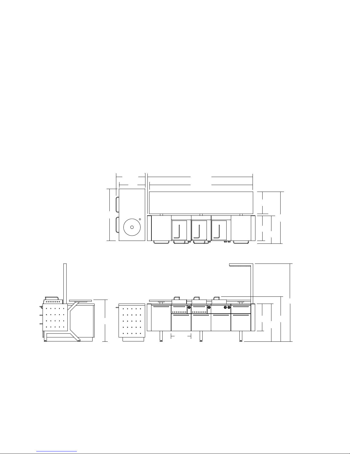
DIMENSIONS
INSTALLER FINAL CHECKLIST:
Speci ed 12 clearances maintained to
combustibles.
Veri ed proper enclosure ventilation.
Drawers fully close.
All internal packaging removed.
Knobs turn freely.
Each burner lights satisfactorily.
Total weight of unit without counter-tops:
approximately 1200 lbs.
29 25/32"
27"
52 15/32"
Residue pan in place properly and sliding
freely.
Pressure regulator connected and set for
4.0 W.C. Natural, 11.2 W.C. LP gas.
Manual shutoff valve installed and
accessible.
Unit tested and free of leaks.
User informed of gas supply shutoff valve
location.
All grates are assembled and put in place.
103 25/32"
99 23/32"
21 1/4"
49 13/16"
To p
39 49/64"
19 3/32"
Side Front
24 1/64"
25 29/32"
26 25/32"
74 3/4"
42 25/32"
36"
10
Page 11
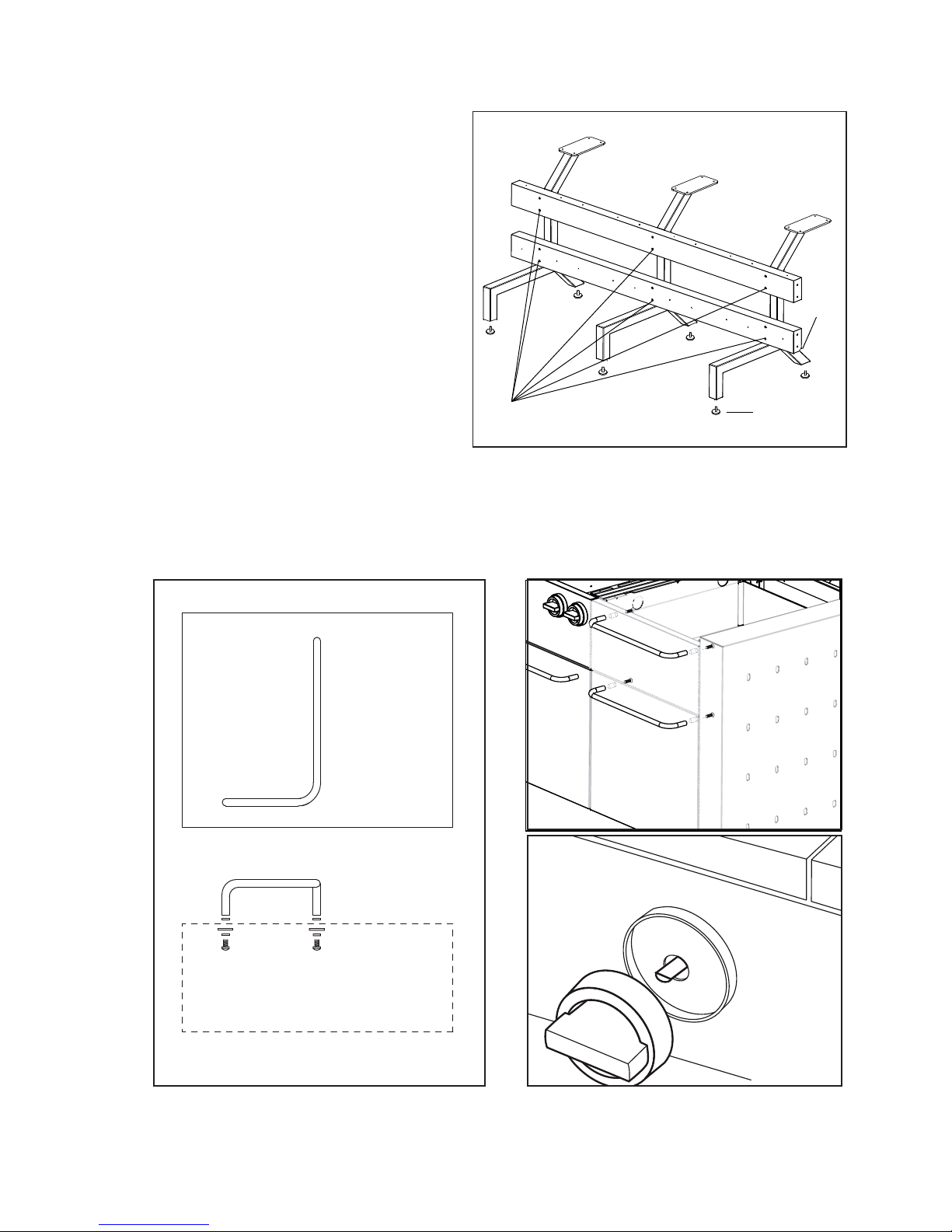
1. Assemble horizontal support beams to
each support frame leg using (12) type
M6x90 screws as shown in Fig. 05. Note
the position of the angled corner on
Beam 2. Assemble (6) leveling feet to
Beam 1
bottom of the support frame legs. Adjust
height of each leveling foot by turning
Beam 2
clockwise. Make sure frame is level before
proceeding.
2. Remove all packing materials from each
of the modular units. It is recommended
you remove the cooking drawers from
each unit prior to installing them onto the
mounting frame. This will give you easy
access to the screw holes and all internal
(12) Screws
Leveling Feet
connections. See Page 16, Fig. 16 for more
information on removing the cooking
Fig. 05
drawers.
3. Assemble handles to each lid and modular unit drawer using screws provided, Fig. 06A and
B. Handles and screws are included in each modular unit box. Secure control knobs to each
grill/cook unit by placing the knob over the valve stem, Fig. 06B
angled
corner
ASSEMBLY: FRAME, HANDLES AND KNOBS
Top view
Slanted Side of Lid
Side view
Fig. 06A
WARNING: H OT!
Handle lid with car e. Use grill mitts when using or r emov ing lid .
Fig. 06B
11
Page 12

ASSEMBLY: MODULAR UNITS
4. Beginning in the center of the
mounting frame, secure the rst grill
unit to the horizontal support beams
by using (2) type M6x12 screws. Fig.
07 Lift up the hinged back panel on
the grill unit to gain access to the top
installaion holes. Pull out the bottom
storage drawer to access the back
installation holes, and use 2 M6x12
screws to attach.
Installation Screw Holes
Hinged Back Panel
Installation Screw Holes
Fig. 07
5. Continue installing each modular
unit to the support beams per the
above instructions making sure to
follow the order shown in Fig.08. If
there are gaps between each unit you
can secure them to each other by using
(1) optional type M6x12 screw with nut,
Fig. 08.
optional screw holes
3
2
1
4
5
Fig. 08
12
Page 13

6. Secure light unit to right side of
modular by using (2) M6x90 type
screws. Fig. 09 Plug power cable
into a 110v outlet. Power cable
can be run through the horizontal
support beam to hide it from view.
Operate lights by using the rocker
switch located on the bottom of
the light shroud. Replace halogen
bulbs with type 50W GU10.
ASSEMBLY: LIGHT UNIT AND END PANELS
Light Shroud
Screw
Holes
Fig. 09
7. Secure left and right end panels
to modular by using (4) type
M6x12 screws per panel. Panels are
labeled A (no light) and B (w/light),
Fig. 10. You will need to remove the
Storage and Warming drawers to
gain access to the installation screw
holes from inside the modular units.
Panel A
Installation
Screws
Fig. 10
13
Page 14

ASSEMBLY: GAS CONNECTIONS
8. Connect the (3) metal gas hoses located in the back of each modular Cook/Grill Unit to the
gas coupler on the opposite end, Fig.11. The right side of each hose is pre-connected at the
factory. Tighten each tting with a wrench to ensure a tight seal.
coupler
Fig. 11
Natural Gas Installation (standard)
9a. Using the provided 1/2” exible gas
hose, connect one end to the rst gas
coupler located inside the left side Storage
Unit, Fig. 12-A. Run opposite end of hose
through left side end panel and connect to
the main natural gas line with shutoff valve,
Fig.12-B.
Grill burner ori ce size: 1.89mm
Cook burner ori ce size: 1.50mm
A
B
Fig. 12
14
Page 15

LP Gas Installation (optional, not included)
9b. Purchase LP conversion kit FA20ALP. Using
the provided LP gas hose, connect end without
regulator to the rst gas coupler located
inside the left side storage unit, Fig.13-A. Run
opposite end to LP tank and secure it to the gas
outlet. You must also replace the brass ori ces
located in each cooking unit. See page 7 for
more LP gas installation information.
Grill burner ori ce size: 1.30mm
Cook burner ori ce size: 1.05mm
ASSEMBLY: GAS CONNECTIONS
A
B
Note: By default the gas entry point (for
NG and LP) will begin on the left side of the
modular inside the Storage Unit. If you want
the NG entry point to begin on the right side
you will need to relocate the gas termination
cap. The gas termination cap is located in
the cook unit on the right side of the coupler,
Fig. 14. Relocate the gas termination cap to
the left most coupler of the modular unit. The
gas termination cap MUST be in place before
operating.
Fig. 13
termination cap
Fig. 14
15
Page 16

ASSEMBLY: DRAWER INSTALLATION AND GRATE ASSEMBLY
10. Install cooking drawers by
sliding them into into each unit, Fig.
15-A. Lock each drawer in place by
turning the lock at the back of the
drawer counter-clockwise, Fig. 15-B
and Fig. 16
Note: Turn to page 19 if using
optional charcoal drawer instead of
gas or infrared drawers.
A
Fig. 15
B
CAUTION: HOT
Do Not Remove Until Cool
OPEN
11. Remove cast iron frames and
grates from the packing materials
and install over grill and cook units
as shown in Fig. 17.
LOCK
Fig. 16
16
Fig. 17
Page 17

12. Open bottom drawer of each grill and
cook unit and locate the ignitor battery
compartment on the right. Install (1) AA
battery per compartment, Fig. 18.
ASSEMBLY: BATTERY INSTALLATION
Fig. 18
Screw postive battery end into coil. Ensure firm
contact is made before inserting into battery box.
Warning: Lid may get extremely hot while cooking, always
use a grill mitt for hand and arm protection.
Use smaller end of handle to tilt lid in order
to view food while cooking.
When lifting lid, grasp handle in the center
for stability.
17
Page 18

ASSEMBLY: WARMING DRAWER
The warming drawer consists of a top drawer with two dishes that can be used to store ice or
other condiments and a bottom drawer with two cha ng dishes to keep your food warm.
Remove protective lm from all
warming drawer components.
Assemble bottom of warming
drawer per Fig. 19.
Chafing Dishes
Water Pans
Water Pan Frame
Sterno Holders
Sterno Holder
Tra y
Fig. 19
Using the Warming Drawer
1. Fill water pan with about 3/4” to 1-1/2” of hot water.
2. Add food to the cha ng dishes.
3. Slide out Sterno holder tray and add Sterno fuel into the holders. Light with a match. Check
the Sterno to see approximately how long it will burn for. Slide the Sterno holder tray back in.
WARNING:
Cha ng dishes are not used to cook food, they are intended only to keep food warm.
Do not leave an open ame unattended.
Do not use anything but sterno type fuel in warming drawer.
Do not put unit a hot stove or open ame.
Never use chafers without water in the water pans.
Open lids carefully so that rising steam does not burn you face or hands.
Maintaining Chafer Dishes While in Use:
Occasionally stir the food to make sure the bottom doesn’t burn.
If you need to add more Sterno, the old burners may be hot so use tongs to remove them.
The above is intended to be used as a guide. For any questions please do not hesitate to
contact us.
18
Page 19

Optional Charcoal Drawer Model: FA20ACD
Sold separately
CAUTION: Charcoal drawer should be inserted
into position opposite the propane tank. If
using two charcoal drawers, make sure to
remove propane tank and properly store it
before cooking with charcoal.
CAUTION: Follow instructions located on back
of charcoal bag before cooking.
CAUTION: When using lighter uid, follow
instructions on container prior to use.
ASSEMBLY INSTRUCTIONS:
1. Assemble charcoal drawer kit by
following the diagram in Fig.20.
2. Follow reverse instructions on page 17
to remove cast iron grates and remove
cooking drawer.
Note: Mesquite chip holder is optional
and only necessary if using mesquite
chips for added avor.
3. Slide drawer into unit.
FIG. 20
MESQUITE
CHIP HOLDER
CHARCOAL
TRAY
CHARCOAL
BASKET
CHARCOAL
DRAWER
ASSEMBLY: OPTIONAL CHARCOAL DRAWER
4. Add charcoal to top of charcoal tray
and light.
5. Begin cooking.
REMOVAL INSTRUCTIONS:
1. Never remove charcoal drawer while
drawer is hot.
2. Properly dispose of charcoal remains
once charcoal briquettes have been
incinerated.
3. Return emptied charcoal drawer to grill.
WARNING:
Keep the area surrounding the grill free from
combustibles, trash or combustible uids and
vapors such as gasolines or charcoal lighter
uid. Do not obstruct the ow of combustion
or ventilation air.
WARNING:
Never leave grill unattended and keep out of
reach of children.
ASSEMBLED DRAWER
NOTE
: CHIP
HOLDER
RESTS UNDER
CHARCOAL
BASKET HANDLES
WARNING:
Use caution when using lighter uid to ignite
charcoal, follow manufacturers instructions on
the back of the lighter uid container.
19
Page 20

ASSEMBLY: UTILITY UNIT
13. The Utility Unit Housing is shipped in three
boxes and must be assembled, Fig. 21. Begin
by attaching bottom panel A to the back panel
using (2) type 5/32x 3/8" screws. Assemble
leveling feet to each side panel. Secure the
two side panels (B) to the back panel using
(4) type 5/32”x 3/8” screws for each panel.
Finalize the Utility Unit Housing by placing
the counter-top base on top of the assembled
frame and secure using (4) type 5/32”x 3/8”
screws.
C
B
A gang box cut-out is built in to
accomodate AC power entry. Purchase an
outdoor gang box from your local hardware
store, Fig. 22.
15. Assemble all handles and leveling feet to
the 24” storage units. Slide each storage unit
into Utility Unit Housing to t in place, Fig. 23.
16. Should you choose not to use the storage
units, the Utility Unit has space to accomodate
(2) 24” refrigerators or (1) 48” refrigerator.
The refrigerators can be plugged into the
gang box. An overlay kit is also available
to t over select refrigerators, see optional
accessories on page 31 for more information.
A
Fig. 21
Gang Box
Opening
Fig. 22
B
20
Fig. 23
Page 21

The Utility Unit has hollow openings in the
counter-top base to accomodate a sink.
The bottom panel of each storage unit is
removable to accomodate plumbing for
a sink on either side. Follow instructions
included with sink for more details on
installation, Fig. 24.
17. Following the dimensions in Fig.25 create
counter-tops to be placed on the Modular
Frame and Utility Unit.
if you have purchased the counter-top
package from Fuego, please follow the
installation instructions enclosed with the
set.
ASSEMBLY: COUNTER-TOPS
19 5/8”
19 5/8”
Fig. 24
27 31/64”
21 1/4”
99 23/32”
52 52/64”
Fig. 25
21
Page 22

ASSEMBLY: COUNTER-TOPS
Dining Unit Counter-Top
Finished dimensions. Please account for
shrinkage depending on material used.
PLYWOOD OR METAL SUPPORT PLATE
RECESS TO ACCOMODATE
99 23/32"
RECESS SHOULD ALWAYS BE THE SAME TO ACCOMODATE 3/4" PLYWOOD.
NOTE: THIS DIMENSION MAY VARY DEPENDING ON MATERIAL.
21 1/4"
1 1/2" THK
ALL EDGES AND CORNERS
INCLUDING SINK CUT-OUT
R3 TYP
SECTION A-A
3/4"
1 1/2"
1 1/2"
TYP
22
Page 23

Utility Unit Counter-Top
.
Finished dimensions. Please account for
shrinkage depending on material used.
ASSEMBLY: COUNTER-TOPS
52 29/64"
ALL EDGES AND CORNERS
INCLUDING SINK CUT-OUT
R3 TYP
27 31/64"
1 1/2" THK
3/4"
1 1/2"
NOTE: UTILITY UNIT FRAME
SERVES AS COUNTERTOP
SUPPORT—NO NEED FOR PLYWOOD
1" TYP
SECTION A-A
23
Page 24

USING THE GRILL : GRILLING
REPLACEMENT OF REGULATORS AND HOSE:
The pressure regulator and hose assembly supplied with the unit must be used. The replacement
pressure regulators and hose assembly must be the type speci ed by the manufacturer, part
number FA00AGC for natural gas or FA00ALP for LP. Do not use the grill if the odor of gas is
present. If the unit is LP, screw the regulator into the tank and leak check the hose and regulator
connections with a soap and water solution before operating the grill. Turn all knobs to “OFF”
then turn on the gas supply. If LP, verify there is gas in the tank.
IMPORTANT - USING THE GRILL:
Grilling requires high heat for searing and proper browning. Most foods are cooked at the
heat setting for the entire cooking time, however, when grilling large pieces of meat or poultry,
it may be necessary to turn the heat to a lower setting after the initial browning. This cooks the
food throughout without burning the outside. Foods cooked for a long time or basted with a
sugary marinade may need a lower heat setting near the end of the cooking time.
Always keep your face and body as far away from the grill as possible when lighting.
•
DO NOT leave the grill unattended while cooking.
•
Keep a spray bottle of soapy water near the gas supply valve and check the connections
•
before each use.
Do not attempt to light the grill if the odor of gas is present.
•
Wait 5 minutes before relighting a hot grill.
•
1. Check to be certain the residue tray is in place.
2. Light the grill burners by pushing the control knob and turning to HIGH.
3. Close the lid and preheat the grill for 10 minutes.
4. Place the food on the grill and cook until done. Adjust heat setting if necessary. The
control knob may be set to any position between
the two positions.
5. Turn knob to
residue tray after each use.
GRILLING HINTS:
The doneness of meat, whether rare, medium or well done, is affected to a large degree by
the thickness of the cut. Expert chefs say it is impossible to have a rare doneness with a thin
cut of meat. The cooking time is affected by the kind of meat, the size and shape of the cut,
the temperature of the meat when cooking begins and the degree of doneness desired. When
defrosting meats, it is recommended that it be done overnight in the refrigerator as opposed to
a microwave. This in general yields a juicier cut of meat. Use a spatula instead of tongs or a fork
to turn the meat, as a spatula will not puncture the meat and let the juices run out. To get the
juiciest meats, add seasoning or salt after the cooking is nished and turn the meat only once
(juices are lost when the meat is turned several times). Turn the meat just after the juices begin
to bubble to the surface. Trim any excess fat from the meat before cooking. To prevent steaks
or chops from curling during cooking, slit the fat around the edges at 2-inch intervals.
to turn grill off. Allow grill to cool and clean the grates, residue pan and
and
. Most grilling is in between
24
Page 25

INFRARED SEARING AND COOKING:
Gas Infrared Cooking is a new technology that employs a set of ceramic plates heated by gas
ame. When the ceramic plates are heated, food is cooked by radiant heat similar to charcoal
cooking. Most of the hot air is trapped and therefore greatly reduces food from drying out.
An advantage of infrared cooking is high heat intensity. Fuego’s infrared burner can generate
heat up to 1000 degrees, allowing searing to seal in the natural juices of various foods delivering
full aroma and avor.
While set on low, the infrared burner produces a constant cooking temperature of
approximately 400 degrees; appropriate for most cooking needs.
COOKING MEAT AND STEAKS:
1. Ignite burner and close lid.
2. Set burner on high for 10 minutes to heat cast iron grate.
3. Place food on the grill surface to sear for 1-2 minutes, or until food begins to lift
without sticking.
4. Repeat this process on each side of food.
5. Once food is seared, reduce heat to low, or to a lower setting to cook food to
desired temperature.
COOKING TIPS:
Unlike cooking with conventional gas burners, it may take some time and practice to familiarize
yourself with infrared cooking. Experiment with different types of food and cooking time
to attain the best that infrared cooking technology has to offer.
USING THE GRILL: INFRARED COOKING
Flare-ups: Some food types may yield more are-ups than others. Reduce are-ups by:
a. Trimming excess fat or skin off of food.
b. Reducing cooking temperature.
c. Moving food around the grill surface.
d. Using a water spray bottle to control fare-ups. NEVER DOUSE a are-up with water.
CLEANING AND MAINTENANCE:
1. After cooking is done, turn burner onto the highest setting for 5 minutes to burn off any
excess food on the infrared surface.
CAUTION: ALWAYS ALLOW GRILL TO COOL SUFFICIENTLY BEFORE CLEANING. WATER
MUST NOT MAKE CONTACT WITH THE BURNER SURFACE, WHILE HOT OR COLD.
2. Periodically remove safety screen and vacuum off remaining ash and particles from
infrared plates. Use vacuum hose extension with soft brush head to avoid damage to the
ceramic surfaces.
3. Clean around drawer with mild soap and water.
4. Always leave burners covered to protect from rain or water. Collection of water into
ceramic cells will cause burner to clog and malfunction.
25
Page 26

USING THE GRILL: BURNER ADJUSTMENTS
LOW SETTING ADJUSTMENTS:
The valves on the grill feature an adjustable low setting.
Due to uctuations in gas pressure, heating value or gas
conversion, you may feel it necessary to increase or decrease
gas ow in the low position.
To adjust:
1. Light the burner.
2. Turn the control knob to the lowest setting (all the way
counter-clockwise).
3. Remove the knob.
4. While holding the valve shaft with pliers, insert a thin,
at tipped screwdriver into the shaft and, while viewing
the burner, adjust to a minimum stable ame, Fig.26.
WARNING: IMPORTANT! Before lighting, inspect the gas
supply piping or hose prior to turning the gas “on”. If there is
evidence of cuts, wear or abrasion, it must be replaced prior
to use.
Fig. 26 Low Setting Adjustment
26
Page 27

GRILL BURNER:
Remove grill grates, and burner drawer. Remove diffuser
panel by lifting it up off the burner. Remove screw
holding burner to drawer Fig. 27 by unscrewing counterclockwise. Remove burner by lifting up, on the end, angle
the burner downwards and remove from drawer.
GRILL BURNER FLAME HEIGHT:
The factory burners have been set for the correct air and
gas mixture. The correct ame pattern is shown in Fig. 28.
MAINTENANCE: BURNER
1: Burner tube
2: Tips occasionally icker yellow
3: Light blue
4: Dark blue
If ames do not appear to be uniform throughout the
burner tube, check if the ventilation openings of the
burner tube are blocked by dirt, debris, spider webs,
etc. In order for burner to work properly there must be
no obstructing the ow of combustion or ventilation air.
Proceed with cleaning instructions below.
GRILL BURNER EXTERIOR CLEANING Fig. 29:
Clean the exterior of the burner with a wire brush. Clean
stubborn scale with a metal scraper. Clear any clogged
ports with a straightened paper clip. Never use a wooden
toothpick as it may break off and clog the port. Shake out
any debris. Use a ashlight to inspect the burner inlet to
ensure it is not blocked. If obstructions can be seen, use a
metal wire coat hanger that has been straightened out.
ORIFICE CLEANING
With the burner removed, remove the ori ce and shine
a ashlight through the opening to ensure there is no
blockage. Use a needle to clear any debris. Be extremely
careful not to enlarge the hole or break off the needle.
Fig. 27
Fig. 28
WARNING:
IT IS EXTREMELY IMPORTANT TO CENTER THE BURNER
ON THE ORIFICE PROPERLY TO PREVENT A FIRE
HAZARD OR EXPLOSION.
Fig. 29
27
Page 28

MAINTENANCE: CARE & CLEANING
RESIDUE TRAY CLEANING:
Open storage drawer under each grill unit and slide out
residue tray, Fig.30. Place tray in dishwasher on normal wash
or clean by hand using mild detergent. Dry and replace when
nished. Clean residue tray after every use to prevent grease
and debris from hardening making it more dif cult to clean.
Replacement residue pans are available from our website.
CAST IRON GRATE AND FRAME CLEANING:
Clean the cast iron grate with a wire brush. Clean stubborn
scale with a metal scraper. Use a soap and water solution to
wash away grease and cooking residue. The best time to
begin cleaning is while the grates are still warm but cooling
down. Do not clean if the grates are still hot.
Fig. 30
IGNITER TIP CLEANING:
If lighting the burners is dif cult you may need to clean and
adjust the igniter tip located near the burner ori ce, Fig. 31
To ensure that the igniter lights properly, clean off any
cooking residue that builds up on igniter tip and burner.
First remove cover to access igniter tip by unscrewing single
philips screw. Use a very ne grit sand paper to clean igniter
tip and edge of burner. Igniter tip should be 1/16 to 1/8 inch
away from burner edge. This is the ideal distance for most
effective ignition.
STAINLESS STEEL SURFACE:
Grill should be covered when not in use.
Wipe down stainless steel surface to remove any cooking residue with a clean cotton or
micro ber cloth. Clean stainless steel surfaces with a stainless steel cleaner and apply a polish
to keep your Fuego Modular looking its best.
TEAK SURFACE:
Clean surface using a soft sponge and a solution of mild soapy water. Wash down afterwards
with clean water. Over time the surface of the teak will begin to weather. To ensure that the
wood is maintained, oils and cleaning solutions should be applied. Golden Care Teak Oil is
recommended for use on the teak surfaces.
Fig. 31
Do not use high pressure hoses, steel wool or wire brushes as all and any residue left in the
grain will rust and discolor the wood.
Stubborn and heavily ingrained stains can be removed by sanding with a ne grade of
sandpaper, being sure to work only with the direction of the timber grain. After sanding away
stains like this you may need to re-oil the surface.
28
Page 29

Please read these helpful cooking and maintenance tips before cooking on the Fuego grill.
COOKING OVERVIEW:
It is important that the grill surface be heated up before cooking. Fuego’s grill grates are made
out of cast iron with enamel coating. The cast iron material ensures maximum and uniform
temperature transfer, as well as optimum heat retention for best cooking results. The enamel
coating eases clean up and protects the grates from rusting.
PREPARING THE CAST IRON GRATES:
Before cooking, we recommend coating the cast iron grates with a thick coat of cooking oil (or
spray) to prevent food from sticking to the surface. Coat the cool grate surface before heating.
Also coat the cast iron frames around the grates to help with cleanup and future maintenance.
WARMING UP THE GRILL:
Ignite the grill burner(s), and set the temperature to high. Cover the grill with the lid and
let stand for 10 minutes. This will ensure that the cast iron grates are well heated and ready
for cooking. Heating time might vary depending on the surrounding outside temperature.
Once the grates are heated, retract the lid and start cooking food. Be sure to follow the time
recommendations on page 21.
IDENTIFYING THE SURFACE HEAT ZONES:
Our grills are con gured with a heat diffuser panel under the grate to properly retain and
channel heat from the burners. This panel can easily be removed for cleaning and is
dishwasher safe.
MAINTENANCE: COOKING TIPS
SURFACE HEAT ZONES:
The con guration of our burners enables the surface
area to have two heat zones. The Cooking Zone is the
highest temperature zone and is where all food
should be cooked. The Warming Zone is where food
can be placed to remain warm while the remainder
of the food is nishing cooking, Fig. 32.
WARM ZONE
HO T
ZONE
HO T
ZONE
WARM ZONE
Fig. 32
29
Page 30

MAINTENANCE: COOKING TIPS
COOKING TIMES
30
Page 31

PROBLEM: GRILL BURNERS WILL NOT LIGHT:
Possible solutions:
Attempt to light burner with match. If you are able to light the burner using a match, the issue
must be with the igniter and not with the burner or the fuel source. If you are unable to light the
burner using a match, the issue must be with the burner or fuel source.
IGNITER/BATTERY (ALL MODELS):
1. Press and hold the igniter button. By pushing in on the burner control knob the igniter is
activated. You should hear a clicking sound.
2. If you hear no clicking sound while pushing in burner control knob, replace AA battery.
Battery housing is located inside the storage drawer on the right hand side. Be sure to
insert positive end of battery securely into spring. Install battery by screwing in spring
loaded cap and tightening clockwise into battery compartment.
3. Check to see if any debris is blocking the igniter spark. If debris is blocking spark, clean
igniter tip. Follow instructions on page 26.
4. Igniter tip may not be able to deliver a spark if too far from burner. Make sure igniter tip
is between 1/16 to 1/8 inch from burner. If not, then adjust by gently bending igniter tip
into proper position.
5 . Burner knob must be turned to light position thus allowing gas ow to reach igniter tip.
TROUBLESHOOTING YOUR FUEGO GRILL
PROPANE TANK (ALL MODELS):
1. If using propane tank, the propane valve must be in the open position. Turn valve
counterclockwise to open. If valve was in open position, turn valve clockwise to close and
then reopen valve slowly.
2. Be certain that gas hose is straight; if kinked, straighten hose to ensure unrestricted gas
ow.
3. Be sure the propane tank is lled, if not, remove and replace tank.
BURNER DRAWER:
1. Try removing drawer and replacing it while ensuring proper connection is made with male
and female igniter ends and ensuring that the drawer is in a xed, snug position. Lock
drawer into place.
2. Try switching positions of drawers from one module to the other. This may allow igniter
connection to t more snugly.
PROBLEM: FLAREUPS (FOR INFRARED ONLY):
Note: Some are-up is natural due to the intense heat of the infrared burner and especially
greasy or fatty foods. In general are-ups can be controlled by simply moving food around on
the grill surface and/or by lowering the heat.
Possible solutions:
1. Check to see that ceramic plates and/or grates are free of grease build-up.
2. If build-up occurs on ceramic plates follow instructions in the User Manual for
cleaning procedures.
3. Be sure that grease drip tray is clean.
4. Ori ce may need to be changed to smaller size (see Infrared instruction page).
31
Page 32

TROUBLESHOOTING YOUR FUEGO GRILL
PROBLEM: GRILL IS NOT HOT ENOUGH
Possible Solutions (All Models):
1. For best results, be sure to preheat grill 10 minutes before grilling. To preheat grill, light
burner and turn burner to highest position. After preheating grill, adjust burner knob to
desired cooking temperature.
2. Double check to see that there is fuel in the propane tank. If not re ll tank or replace with
lled tank.
3. Be sure gas hose is straight. If kinked, straighten hose to ensure unrestricted gas ow.
4. Liquid propane regulators incorporate a safety device. This device is designed to sense
unrestricted gas ow and to cut back on the pressure. By opening the propane valve
too far or too quickly, the safety device may be activated. Low heat on the grill may be
an indication that this safety device has been triggered. This can be avoided by opening
the propane valve only 1/4 turn when lighting the grill. This may prove to be all the gas
required for your cooking needs, however, if you need more gas for a higher ame, open
the valve further using 1/4 turn increments until the ame reaches the desired height. If
you feel that the safety device has been activated, turn the propane valve completely to
the closed position and disconnect the tank. After ve minutes, reconnect the tank and
try again.
5. Natural gas pressure may vary from community to community. Also your home may have
been equipped with in-line natural gas regulators that can impact the pressure to the grill.
If you nd that your natural gas grill does not get up to a desired temperature on a regular
basis, your gas pressure may well be below the standard to which the grill is designed.
Often times the ori ce size can be adjusted to compensate. It is recommended that a
professional assess the gas line at this point before determining a solution to this problem.
GENERAL TROUBLESHOOTING:
Fuego recommends inspection of burners at least once per year. Fuego recommends you
inspect burners immediately if any of the following occur:
1. You smell gas in conjunction with the burner ames appearing yellow.
2. Grill does not reach desired temperature.
3. Burners make any unusual sounds.
Please refer to the User Manual for tips on the care and cleaning of the Fuego burner.
Keeping your grill clean and the grease drip tray beneath the grill empty will aid in ensuring
trouble free operation of your Fuego Grill. Your grill should be lightly cleaned after each use.
Always check to make sure that the propane valve has been closed and disconnected before
putting your grill away. We recommend using Fuego’s optional outdoor cover between uses.
Propane is extremely ammable, and extreme care should be taken during the use and the
storage of your grill. Following these simple steps should yield years of trouble free use of your
Fuego Grill.
IF PROBLEMS PERSIST OR IF YOU EXPERIENCE ANY FURTHER ISSUES WITH YOUR FUEGO
GRILL, CONTACT FUEGO NORTH AMERICA BY PHONE AT 888-88-FUEGO (888-883-8346)
OR ONLINE AT WWW.FUEGOLIVING.COM.
32
Page 33

OPTIONAL FUEGO MODULAR ACCESSORIES:
FA20ADC Dining Unit Counter-top
FA20AUC Utility Unit Counter-top
FA20ASS Stainless Steel Sink
FA20AUF Faucet
FA20ACD Charcoal Drawer Option
FA20AID Infrared Drawer Option
FA20AGD Gas Drawer Option
FA00ATH Paper Towel Holder
FA00ACT Ceramic Tray Set
FA00ASP Spice Accessory Jars (8)
FA00ABB Beverage Bucket
FA00AGP Griddle/Flat Plate
FA00ALL 7” Large Cooking Lid
FA20ALP LP Conversion Kit
ACCESSORIES
Accessories may be purchased from your local dealer. Part numbers, pricing and availability
subject to change without notice. Contact your local dealer for more information.
33
Page 34

WARRANTY
LENGTH OF WARRANY:
One (1) Year comprehensive parts and labor on the entire product.
Five (5) Year limited parts warranty covering the cast iron grill grates and frame.Should structural
deterioration occur to the degree of non-performance, a replacement will be furnished.
Lifetime Warranty covers all stainless steel components against manufacturer related defects. This
excludes discoloration or surface corrosion resulting from improper use and care.
FUEGO WILL PAY FOR…
All repair labor and parts found to be defective due to materials or workmanship for one full year “IN
HOME” warranty during the rst year of ownership. This does not apply if the unit was subjected to
other than normal household use. Service must be provided by Authorized Factory Technician during
normal working hours. No charges will be made for repair or replacement at the location of initial
installation or factory for parts return pre-paid, through the dealer and claimed within the warranty
period, and found by Fuego to be defective.
Replacement will be F.O.B. Fuego, and Fuego will not be liable for any transportation costs,
labor costs, ar export duties. This warranty shall not apply, nor can we assume responsibility for
damage that might result from failure to follow manufacturers instructions or local codes, where
the appliance has been tampered with or altered in any way or which, in our judgment, has been
subjected to misuse, negligence, or accident.
FUEGO WILL NOT PAY FOR…
• Installation or start-up.
• Shipping damage.
• Service by an unauthorized technician.
• Damage or repairs due to service by an unauthorized technician or the use of unauthorized
parts.
• Service during other than normal working hours.
• Improper installation, such as improper hook-up, etc.
• Service visits to teach you how to use the appliance, correct the installation, reset circuit
breakers or replace home fuses.
• Repairs due to other than normal household use.
• Damage caused from accident, abuse, alteration, misuse, incorrect installation or installation
not in accordance with local codes.
• Units installed in non-residential application such as day care centers, bed and breakfast
centers, churches, nursing homes, restaurants, hotels, schools, etc.
This warranty applies to appliances used in residential applications; it does not cover their use in commercial
situations. This warranty is for products purchased and retained in the 50 states of the U.S. A., the District of
Columbia and Canada. This warranty applies even if you should move during the warranty period. Should the
appliance be sold by the original purchaser during the warranty period, the new owner continues to be protected
until the expiration date of the original purchaser’s warranty period.
This warranty is in lieu of all other warranties, express or implied, and all implied warranties, including warranties
of merchantability and tness for a particular purpose, are hereby disclaimed to the full extent permitted by law.
To the extent that implied warranties may not be disclaimed, the duration of any implied warranties, including
implied warranties of merchantability and tness for a particular purpose, are limited to the extent of this express
warranty. This warranty gives you speci c legal rights. You may also have other rights which vary from state to
state.
Fuego Customer Service: 1.888.88.FUEGO
www.fuegoliving.com
Write To: Fuego North America
Roundhouse One, 1500 Sansome Street #100
San Francisco, CA 94111
34
Page 35

35
 Loading...