

Page 1
Phottix Odin TTL Trigger for Canon
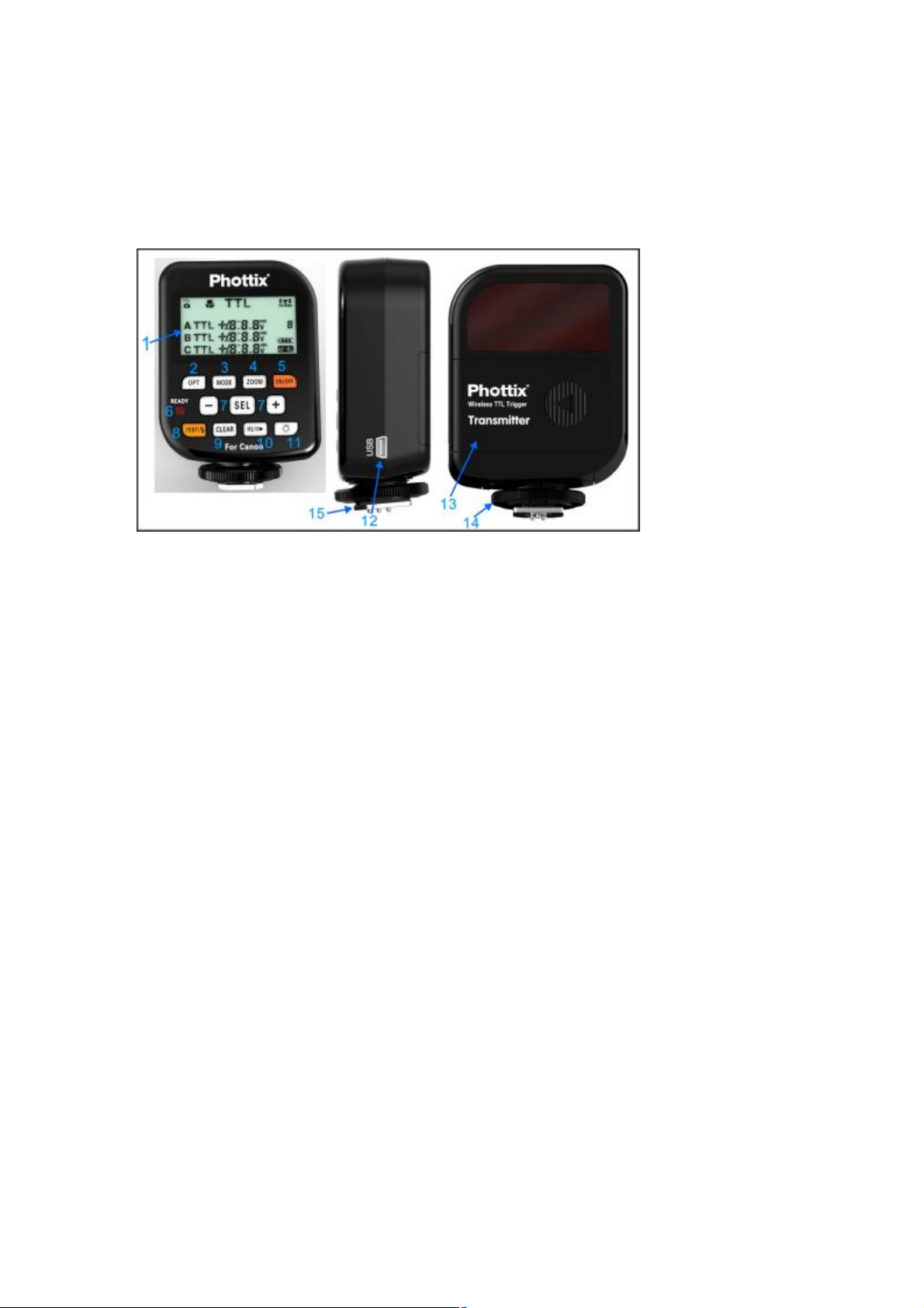
Parts
Transmitter Control Unit (TCU)
1. LCD Screen
2. Options Button
3. Mode Button
4. Zoom Button
5. Power Button
6. LED
7. + / - / Selection Buttons
8. Test Button
9. Clear Button
10. High Speed Sync / Second Curtain Sync Button
11. LCD Backlight Button
12. USB Port
13. Battery Compartment
14. Locking Ring
15. Hot Shoe
Please Note: After adding turning on the Phottix Odin TCU and receivers you
must take one photograph for the TCU to “learn” about your camera and flashes.
The first shot you take will not be properly exposed. Subsequent images will be
correct.
Slave mode does not need to be set on flashes on Phottix Odin receivers.
Many TTL flashes have been tested but the manufacturer cannot guarantee that
all third party TTL flashes will function properly with the Phottix Odin. It has been
designed and optimized for original Canon flashes using the ETTL II system.
Tip: Turn off all devices – flashes/strobes, cameras, and the Phottix Odin TCU
and receivers - when connecting and disconnecting devices.
Page 2

Upgrading firmware by USB
The firmware of the TCU and receivers can be upgraded using the included USB
cable. Any upgrades and full instructions will be announced on the Phottix Blog
(journal.phottix.com).
LED functions
The LED on the TCU and receiver units will turn green when the camera is
focusing and red when a photo is being taken.
Inserting batteries
1. Press the battery cover in while pushing it away from the Phottix Odin
TCU or receiver. The battery cover will slide open.
2. Remove the battery cover.
3. Insert AA batteries as shown.
4. Replace the battery cover and push back into the locked position.
5. When the battery power icon on the TCU shows low battery levels change
the batteries.
6. When the power is very low, the LED will flash red light every 2 seconds.
Turning the TCU and receiver on/off
1. To turn on the Phottix Odin TCU: Press and hold the Power Button until an
image appears on the LCD screen. To turn off: Press and hold the Power
Button until the LCD screen goes blank.
2. To turn on the Phottix Odin receiver: Move the power switch to the “ON”
position. Turn off the receiver by moving the power switch to the “OFF”
position.
Groups and Channels
1. The Phottix Odin System has 3 groups: A, B, and C, and 4 tranmission
channels: 1, 2, 3, 4.
2. Receivers can be assigned both group and channel designations.
3. The transmitter will allow power levels and changes to be set for each
group. Unless turned off on the TCU, all receivers set to the same channel
and group will fire.
The TCU
Connecting to the camera hot shoe
1. Turn off the camera.
2. Slide the Odin TCU into the camera’s hot shoe mount. Turn the TCU
locking ring until tight.
3. Turn on the Odin TCU (see above).
4. Turn on the camera.
Functions
The TCU has two main function screens: TTL/Mixed and Ratio.
Page 3

TTL/Mixed allows groups A, B and C to be set to TTL, Manual or OFF with
adjustments to EV or power levels.
Ratio is similar to Canon’s native TTL system. The ratio of groups A and B can
be set from 8:1 to 1:8. EV levels can also be adjusted.
To change function screens:
Press the Option button on the TCU. The Option Button will switch between
TTL/Mixed and Ratio screens.
TTL/Mixed Functions Screen
The Selection Button allows you to cycle through groups A, B, and C, and
Channel selections. Active selections will flash on the LCD. The - / + buttons will
change the EV adjustments or Power Level while groups A, B or C are selected
and will change the transmission channel (1, 2, 3 or 4) when Channel is selected.
This will change the channel the TCU uses to transmit.
TTL / M / Off
While groups A, B or C are selected, pressing the Mode button will change from
TTL, (M) Manual, or Off functions.
TTL: Will fire flashes using TTL metering. The EV level of each group can be
adjusted up or down (see above)
M: Flashes can be set in Manual mode and power levels adjusted.
Off: Selecting Off (signified by three underscores _ _ _) will turn off the selected
group and not fire any remote flashes in that group.
Ratio Functions Screen
The Selection Button allows you to cycle through ratio A:B adjustment, EV
adjustment and Channel selections.
Press the Selection button to access ratio adjustments. Press the + / - button
until the desired A:B ratio is achieved.
Pressing the Selection button again will move the active selection to the EV
adjustment section. Press the + / - button until the desired EV level is achieved.
Transmission channels can be changed when CH is active. This will change the
channel the TCU uses to transmit.
Adjusting flash zoom
The Phottix Odin allows the zoom level of flashes to be set wirelessly. Zoom can
be set as TTL or Manual. When TTL is selected: The flash zoom setting will
change dynamically as a camera zoom ring is adjusted. In Manual mode, the
flash zoom can be set.
Page 4

Using Zoom:
1. Press the Zoom Button to enter the Zoom screen.
2. Pressing the Selection button will cycle through groups A, B and C, and
Transmission channel.
3. Note: Pressing the Selection button after the CH selection will return to the
TTL/Mixed or Ratios Function Screens。
4. With groups A, B or C active: Press the Mode Button to change from TTL
to Manual mode. In Manual Zoom, press the - / + buttons to adjust the
flash zoom. No adjustments can be made in TTL mode.
Using the Clear Button:
1. The Clear Button will erase any setting currently in the TCU.
2. Press the Clear button to remove TT/M/Off, Ratio, Zoom and EV settings
currently in the TCU.
Using the Test Button
The test button will fire all flashes connected to Phottix Odin receivers that are on
the same channel as the TCU.
1. Press the Test button.
2. Flashes will fire in sequence: Group A, followed by Groups B and C.
Using High Speed Sync (HSS) and Second Curtain Sync (SCS)
Pressing the HSS/SCS button will cycle between HSS, SCS and standard
operations.
1. HSS will allow shutter speeds longer than a compatible cameras specified
shutter speed to be used. Shutter speeds up to 1/8000 sec. can be achieved
with compatible cameras and flashes.
2. Note: At high shutter speeds the power of flashes is greatly reduced. EV or
power levels cannot be adjusted when HSS is used.
3. SCS will fire the flash at the end of an exposure, not at the beginning. This
can be combined with longer exposures for creative effects.
Using the LCD Backlight.
The LCD Backlight Button will turn the LCD Backlight on for approximately 10
seconds. If no buttons on the TCU are pressed the light will go off.
Technical Specifications
Frequency: 2.4 GHz
Distance: 100m+
Channels: 4 channels
Groups: 3 groups – A, B, C
Batteries: 2 x AA batteries
Max sync speed: 1/8000 sec*
Page 5

Input: USB port (transmitter and receiver)
Input voltage: 2.4-3.2V
Flash port voltage handling: 6V (transmitter)
Body dimensions: 94(L) x 66(W) x 35(H) mm, (transmitter),
Antenna: built-in PCB antenna
Weight: 105g (transmitter)– without batteries
Operating temperature: -15—65 ℃
Storage temperature: -30—85 ℃
* On compatible cameras / flashes
Warnings
- This product is a precise electronic instrument. Do not expose to damp
environments or dust.
- Do not drop or crush
- Do not use harsh chemical(s) or solvents to clean the body. Use a soft
cloth or lens paper.
- Interference: The Phottix Odin transmits and receives radio signals at 2.4
GHz. Its performance can be affected by electrical current, magnetic fields,
radio signals, wireless routers, cellular phones, and other electronic
devices. Environmental objects, such as large buildings or walls, trees,
fences, or cars can also affect performance. If your Phottix Odin receiver
will not trigger move its location slightly.
Page 6

FCC ID:
XBYFKT05ZA
changes or modifications not expressly approved by the party responsible for
compliance could void the user's authority to operate the equipment.
NOTE: This equipment has been tested and found to comply with the limits for a
Class B digital device, pursuant to Part 15 of the FCC Rules. These limits are
designed to provide reasonable protection against harmful interference in a
residential installation. This equipment generates, uses and can radiate radio
frequency energy and, if not installed and used in accordance with the
instructions, may cause harmful interference to radio communications. However,
there is no guarantee that interference will not occur in a particular installation.
If this equipment does cause harmful interference to radio or television reception,
which can be determined by turning the equipment off and on, the user is
encouraged to try to correct the interference by one or more of the following
measures:
-- Reorient or relocate the receiving antenna.
-- Increase the separation between the equipment and receiver.
-- Connect the equipment into an outlet on a circuit different
from that to which the receiver is connected.
-- Consult the dealer or an experienced radio/TV technician for help.
This device complies with Part 15 of the FCC Rules.
Operation is subject to the following two conditions:
(1) this device may not cause harmful interference,
and (2) this device must accept any interference
received, including interference that may cause
undesired operation.
 Loading...