


Instruction for Use
lnfrared Thermometer (Contact Type)
FT-F11-BT,FT-F21-BT, FT-F12-BT, FT-F22-BT
FT-F11, FT-F21, FT-F12, FT-F22
UO8080, UO8080E
- 1 -
INFRARED THERMOMETER
(FT-F11-BT, FT-F21-BT, FT-F12-BT, FT-F22-BT;
FT-F11, FT-F21, FT-F12, FT-F22, UO8080, UO8080E)
Operating Instruction
Please read carefully before use.
DESCRIPTION
1. Table of Contents
1. Product Listing
2. Product Overview
3. Outline Drawing
4. The Definition of Symbols
5. Measuring
6. Battery Voltage Display & Replacement
7. Operation Precautions
8. Precaution for Measuring Temperature
9. Product Specification
10. Common question concerning forehead temperature
2. Product Overview
This infrared Thermometer measure the temperature. It can get more quick and accurate
from human body temperature.
This product has the following advantages:
1). Easy to Clean the Probe.
2). High speed & Accuracy scan the reading of temperature.
3). Convenience, Only one key operation.
4). 12 memories recall.
5). Last measured temperature data displayed, when you turn on the power.
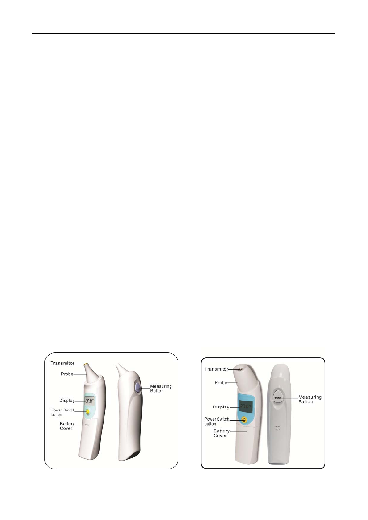
3. Outline Drawing
FT-F11-BT&FT-F11
FT-F21-BT & FT-F21
- 2 -
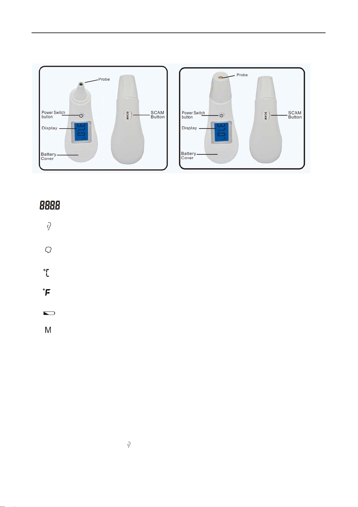
FT-F12-BT &FT-F12 FT-F22-BT&FT-F22
4.The Definition of Symbols
Reading Display
Celsius Scale
Ear Measuring mode (Suitable for FT-F11, FT-F12 & FT-F21, FT-F22
FT-F11-BT, FT-F21-BT; FT-F12-BT, T-F22-BT; UO8080)
Forehead Measuring mode (Suitable for FT-F21,FT-F22 & FT-F21-BT
FT-F22-BT, UO8080E)
Fahrenheit Scale
Low Battery
Last Memorized Temperature Display
5. Measuring
1) Ear Measuring Mode (Figure 5.1) (Suitable for FT-F11, FT-F11-BT, FT-F21, FT-F21-BT,
FT-F12,FT-F12-BT,FT-F22,FT-F22-BT,UO8080, UO8080E)
●Turn on the “power” button key of the IR Thermometer and then all displayed segments
appear briefly as like on(Figure 5.2); the displayed screen appears last measured
temperature data, please see on (Figure 5.3); after few seconds automatically change to
the Ear Measuring Mode ” ” symbol appears on the displayed screen and the
- 3 -
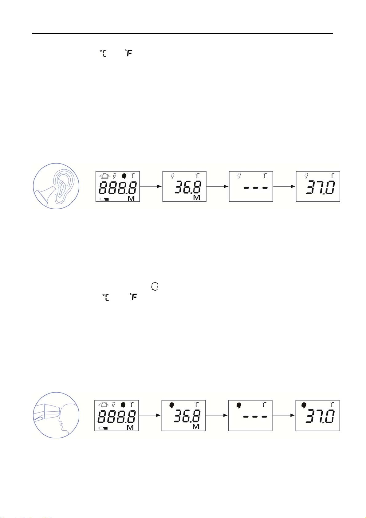
temperature unit“ ” or “ ” blink it’s ready to measure, please see on( Figure 5.4)
●Insert the IR Thermometer probe into the ear canal as on the following (Figure 5.1); Pull
the ear slightly back ward to straighten the ear canal. Then insert the probe into the ear as
far as it goes. Be sure the probe fully seals the ear canal. Hold this position until the
measurement is completed.
●Press the “ SCAN “ button key to wait about 1 second then you can hear the long “Bi--”
sound that it’s finished the measurement in the meantime the measured temperature data
appears on the displayed screen. (Figure 5.5)
●Remove the IR thermometer from the ear canal and read measured data on the displayed
screen. If you don’t use again, the power will be automatically switch off within 60 seconds.
Figure 5.1 Figure 5.2 Figure 5.3 Figure 5.4 Figure 5.5
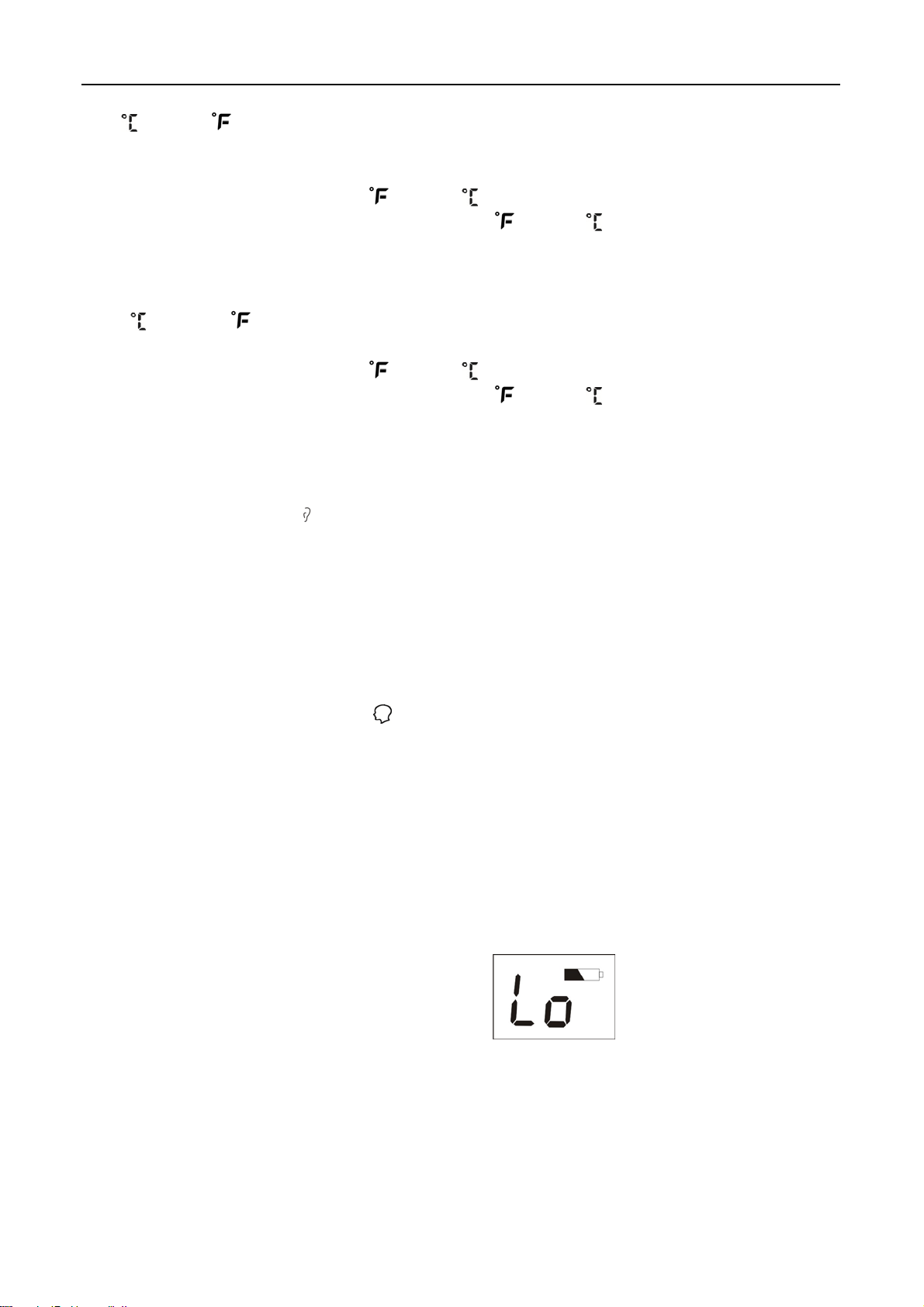
2) Contact Type Forehead Measuring mode (Figure5.1A)(Suitable for FT-F21,FT-F22 &
FT-F21-BT,FT-F22-BT, UO8080E)
●Turn on the “power” button key of the IR Thermometer and then all displayed segments
appear briefly as like on(Figure 5.2A),the displayed screen appears last measured
temperature data, please see on (Figure 5.3A),after few seconds automatically change to
the Forehead Measuring Mode “ ” symbol appears on the displayed screen and the
temperature unit “ ”or “ ” blink then it’s ready to measure, please see on (Figure
5.4A).
●Put the probe in the middle of forehead position and press the “SACN” button key then
keep moving the IR thermometer from the middle of forehead to the side of forehead then
you will hear long “Bi--” sound that It is finished the measurement in the meantime the
measured temperature data appears on the displayed screen, the measuring time takes
about 1 second .(see on Figure 5.5A).
●Remove the IR thermometer from the forehead and read measured data on the displayed
screen. If you don’t use again, the power will be automatically switch off within 60
seconds.
Figure 5.1A Figure 5.2A Figure 5.3A Figure 5.4A Figure
5.5A
- 4 -
3)“ ” and“ ”adjust (Suitable for FT-F11,FT-F21,FT-F11-BT,FT-F21-BT, UO8080,
UO8080E)
● On power off condition, press the “SCAN” button key about 5 seconds until the displayed
screen appears “- - -” and “ ” or “ ” temperature unit blinks . In this condition,
press the “SCAN” button key again to adjust “ ””or “ ” and then it is set up ready
for use.
“ ” and“ ”adjust (Suitable for FT-F12,FT-F22,FT-F12-BT,FT-F22-BT)
●On power off condition, press the “SCAN” button about 10 seconds until the displayed
screen appears “- - -” and “ ” or “ ” temperature unit blinks . In this condition,
press the “SCAN” button key again to adjust “
””or “ ” and then it is set up ready
for use.
4)Ear and Forehead measuring mode switch
●On power off condition, press the “Power” button about 5 seconds until the displayed
screen appears or then press the “Scan” button to switch to ear or forehead
measuring mode.
5)Memory recall
●12 memories recall.
●Press “SCAN” button key to display “---M” on the displayed screen, in the power off
condition and then memory recall displays.
●Press again “SCAN” button key to display previous memory in order and the memory
will recall in one second.
●Press “Power” button key to be out of memory recall and then enter process
condition to measure.
6. Battery Voltage Display & Replacement
●LOW battery: The low battery symbol will be shown at the lower batter on the displayed
screen during the low battery power.
Replace the battery as soon as possible. However you can continue to use it on short time.
(Figure 6.1)
Figure 6.1
●Replace battery:
1). Open battery cover, remove the old battery out.
2). Insert new battery inside the bottom, please be careful the batteries polarity.
- 5 -

7. Operation Precautions
1). Please insert the battery into the bracket when do you use the IR Thermometer on first
time.
2). Please keep the probe clean after you used the IR Thermometer.
3). Please keep the IR Thermometer dry and never immerse it in water or any liquid.
4). Do not put the IR Thermometer under high temperature environment on long time
and keep away from sunlight, dust and dirt.
5). Do not put the IR Thermometer with keen-edged goods together.
6). Do not touch the tip of probe with your finger.
7). Do not disassemble the IR Thermometer.
8). Do not use the IR Thermometer if you suffer from ear disease or your ear canal wet.
9). To obtain a precise temperature measurement, first clean your ear of all excessive
earwax.
10). Please take your temperature when you relax and never take your temperature
after exercise or a bath. Rest at least 30 minutes afterward.
11). Please keep your mobile phone away from the IR Thermometer to prevent malfunction.
12). If the following conditions occur, we recommend you to take your temperature at
least three times and use the highest reading.
13). Please use clean cloth with 70-90% Isopropyl alcohol (IPA) to clean up before or
after use; Avoid multiple using by different peoples for cross infection.
Note:
1. Any solution, dilution and method other than mentioned above might cause reliability
problems with the Infrared thermometer.
2. Contraindications for the following : placing the thermometer probe on scarred tissue or
tissue compromised by skin disorders; patients in trauma;
Patients treated with certain drug therapies; and placing the thermometer probe on skin
exposed to direct sunlight, fireplace heat, cold compress therapies, air conditioner flow,
etc.
3. Not servicing/maintenance while the device is in use.
4. The patient is an intended operator. The patient can measure, transmit data under
normal circumstances and maintain the device and its accessories according to the
user manual.
5. Please remove the batteries if it is not in use for a long time (More than 3 months ).
6. Not intended to be sterilized. Not for use in an OXYGEN RICH ENVIRONMENT
7. Please dispose of the device/battery/accessory/packing in accordance with the legal
obligation in your area
8. Before every use, check the device, Do not use the device if it is damaged in any way.
The continuous use of a damaged unit may cause injury, improper results, or serious
danger.
9. No modification of this device is allowed.
8. Precaution for Measuring Temperature
- 6 -

Description Meaning
Measuring temperature over 43.0℃/109.4℉
Measuring temperature lower than 34.0℃/93.2℉
Environment temperature high than
working temperature.10.0℃- 40.0℃(50.0℉- 104.0℉)
9. Specifications
Model No.
FT-F11, FT-F21, FT-F12, FT-F22; FT-F11-BT, FT-F21-BT;
FT-F12-BT, FT-F22-BT; UO8080, UO8080E
Measuring Range
Measuring time
Accuracy
Resolution
Operation Condition
Storage Condition
Battery type and battery life
Protection against electric
shock
Body 34.0℃-43.0℃( 93.2℉-109.4℉)
minimum measuring time is 2 seconds; and minimum time between
measurements for the same site is 2 seconds
±0.2℃/0.4℉ 34.0℃-34.9℃ (93.2℉- 94.82℉)
±0.2℃/0.4℉ 35.0℃-42.0℃ (95.0℉-107.6℉)
±0.2℃/0.4℉ 42.1℃-43.0℃ (107.78℉-109.4℉ )
0.1℃/0.2℉
10.0℃-40.0℃(50.0℉- 104.0℉)
Rh≤95%
Pressure: 86~106 kPa
-25.0℃-55.0℃(-13.0℉- 131.0℉)
Rh≤95%
Pressure: 86~106 kPa
AAA 2pcs ( Suitable for FT-F11 , FT-F21 ,FT-F11-BT FT-F21-BT,
UO8080, UO8080E)
1 PC 2032 button battery (Suitable for FT-F12,FT-F22 ,FT-F12-BT
FT-F22-BT)
The typical service life of the new and unused batteries is 300
measurements for the operation time is 60s
Internally powered ME equipment
Protection against electric
shock
IP classification
Type BF
IP22 (
IP22: The first number 2: Protected against access to hazardous parts
with a finger, and the jointed test finger of 12 mm Ф, 80 mm length, shall have
adequate clearance from hazardous parts .And protected against solid foreign
objects of 12,5 mm Ф and greater. The second number: Protected against
vertically falling water drops when enclosure titled up to 15º. Vertically falling
drops shall have no harmful effects when the enclosure is titled at any angle
up to 15’’ on either side of the vertical.
Cuff
- 7 -

Mode of operation Continuous operation
L145*W35*H40mm (Suitable for FT-F11, FT-F21 FT-F11-BT FT-F21-BT)
Size (body)
Weight(including battery)
Contents
L120*W44*H60mm (Suitable for FT-F12, FT-F22 FT-F12-BT FT-F22-BT)
L132*W40.3*H65mm (Suitable for UO8080, UO8080E)
78g(FT-F11,FT-F11-BT),80g(FT-F21,FT-F21-BT),
48g(FT-F12,FT-F12-BT;FT-F22,FT-F22-BT)
-infrared thermometer
-batteries 3V (Optional)
-Storage case (Optional)
-Instruction Manual
Bluetooth Version
Bluetooth Modulation Type GFSK
Bluetooth 4.1 BLE
Specially Voice Function for Model no.FT-F11, FT-F21, FT-F11-BT,
FT-F21-BT, UO8080, UO8080E
1. When the IR thermometer is ready, you can hear“Please measure”voice or other
languages voice.
2. When the measurement is finished, the IR thermometer shall report the measured
temperature data.
The Blue Tooth function model is FT-F11-BT, FT-F12-BT,FT-F21-BT
FT-F22-BT)
Operation Method:
★
Install the APK accordance with the communication protocol into the blue tooth
signal receiving device such as mobile phone.
★ Activate the blue tooth signal receiving device such as mobile phone to match
with the blue tooth of infrared thermometer
★ Start to measure according to the normal infrared thermometer operation
method.
★ After measuring the result will be displayed on LCD and be sent to the blue tooth
receiving device such as mobile phone.
The additional function of blue tooth infrared thermometer is to transmit the testing result to
the APK in the receiving device via blue tooth technology.
- 8 -

10. Common questions concerning forehead temperature:
1). What is the forehead temperature?
Forehead temperature is the same temperature as the arterial blood supply under the
skin. It is the best determinate of body temperature, and unaffected by the artificial errors
and time delays of oral and rectal methods.
2). How to take forehead temperature properly?
Gently touch the probe to center of forehead .Make sure remove anything covering the
area to be measured (hair .hat .wig .and bandages). Failure to do so may insulate the
area, resulting in false readings. Press the “SCAN” button on the thermometer for the
reading.
3). Why is a forehead temperature is more accurate than ear temperature?
Ear thermometers are considered inaccurate because the positioning of the probe in the
ear canal might affect the accuracy. The forehead thermometer scans the forehead area
for temperature given off by the arterial blood supply under the skin without worrying
about correct positioning. The gentle scan is comfortable and not invasive.
Temperature measurements are impacted by the type of measurement method used.
Measurement method Normal temperature range Fever temperature range
35.0~38.0℃(95.0~100.4℉)
Forehead
Ear 36.5~37.9℃(97.7~100.3℉) 38.0℃or higher (100.4℉or higher)
NOTED: Measurements for
some adults may be lower
than 35.0℃(95.0℉)
A temperature that is 0.6~0.8℃
(1.0~1.5℉)higher than usual. It is
highly recommended that you use
our IR Forehead Thermometer to
establish the normal temperature
range for each person.
LIMITED WARRANTY
This Infrared thermometer is guaranteed for 2 years from the purchasing date under normal
use .The warranty does not cover the damage of improper use or the battery running out. If
the unit does not function properly due to defective parts or assembly, we will repair it free of
charge or replace with a new one. We will provide circuit diagrams, component part lists,
- 9 -

descriptions, calibration instructions to assist to service personnel in parts repair.
Notes:
If you have any problems with this device, such as setting up, maintaining or using, please
contact with service personnel of FUDAKANG INDUSTRIAL CO.,LTD. Don’t open or repair the
device by yourself.
Please report to FUDAKANG INDUSTRIAL CO.,LTD if any unexpected operation or events
occur.
After drop/ shock…,that may cause changes in the performance , please contact with
service personnel of FUDAKANG INDUSTRIAL CO.,LTD.
Don’t open or repair the device by yourself.
Keep the device out of the reach of children/pets to avoid inhalation or swallowing of small
parts.
The device should be used only with the accessories recommended for use by the
manufacturer.
This device must only be serviced, repaired and opened by individuals at authorized sales
centers .
This device is not a life supporting me equipment
Statement: Clinical accuracy characteristics and procedures are available from the
manufacturer on request.
STATEMENTS AND DECLARATIONS:
1. MEDICAL ELECTRICAL EQUIPMENT needs special precautions regarding EMC and needs to
be installed and put into service according to the EMC information provided in the ACCOMPANYING
DOCUMENTS
2. Wireless communications equipment such as wireless home network devices, mobile phones,
cordless telephones and their base stations, walkie-talkies can affect this equipment and should be
kept at least a distance d = 3,3 m away from the equipment.
(Note. As indicated in Table 6 of IEC 60601-1-2:2007 for ME EQUIPMENT, a typical cell phone with
a maximum output power of 2 W yields d = 3,3 m at an IMMUNITY LEVEL of 3 V/m)
3. The manufacturer are available for request of circuit diagrams, component part lists,
descriptions ,calibration instructions ,or other information that will assist service personnel to
repair those parts of the device
4. Changes or modifications not expressly approved by the party responsible for compliance could
void the user’s authority to operate the equipment.
- 10 -

This equipment has been tested and found to comply with the limits for a Class B digital device,
pursuant to Part 15 of the FCC Rules. These limits are designed to provide reasonable protection
against harmful interference in a residential installation. This equipment generates, uses and can
radiate radio frequency energy and, if not installed and used in accordance with the instructions,
may cause harmful interference to radio communications. However, there is no guarantee that
interference will not occur in a particular installation.
If this equipment does cause harmful interference to radio or television reception, which can be
determined by turning the equipment off and on, the user is encouraged to try to correct the
interference by one or more of the following measures:
-- Reorient or relocate the receiving antenna.
-- Increase the separation between the equipment and receiver.
-- Connect the equipment into an outlet on a circuit different from that to which the receiver is
connected.
-- Consult the dealer or an experienced radio/TV technician for help.
5. Guidance and manufacturer’s delclaration
Guidance and manufacture’s declaration – electromagnetic emission
The [EQUIPMENT or SYSTEM] is intended for use in the electromagnetic environment specified below. The customer of
the user of the
[EQUIPMENT or SYSTEM] should assure that it is used in such an environment.
Emission test Compliance Electromagnetic environment –
guidance
The [EQUIPMENT or SYSTEM] use RF
energy only for its internal function.
RF emissions
CISPR 11
RF emission
CISPR 11
Harmonic emissions
IEC 61000-3-2
Voltage fluctuations/ flicker
emissions
IEC 61000-3-3
Group 1
Class B
Not applicable
Not applicable
Therefore, its RF emissions are very low
and are not likely to cause any
interference in nearby electronic
equipment.
Guidance and manufacture’s declaration – electromagnetic immunity
The [EQUIPMENT or SYSTEM] is intended for use in the electromagnetic environment specified below. The customer
or the user of
Immunity test
[EQUIPMENT or SYSTEM] should assure that it is used in such an environment.
IEC 60601 test
level
Compliance
level
Electromagnetic
environment -
- 11 -

Electrostatic discharge
(ESD)
IEC 61000-4-2
Electrical fast
transient/burst
IEC 61000-4-4
Surge
IEC 61000-4-5
Voltage dips, short
interruptions and voltage
variations on power
supply input lines
IEC 61000-4-11
Power frequency (50Hz)
magnetic field IEC
61000-4-8
NOTE UT is the a.c. mains voltage prior to application of the test level.
±6 kV contact
±8 kV air
±2 kV for power supply lines
±1 kV for input/output lines
±1 kV differential mode. ±2 kV
common mode
<5% UT
(>95% dip in UT)
for 0.5 cycle
40% UT
(60% dip in UT)
for 5 cycles
70% UT
(30% dip in UT)
for 25 cycles
<5% UT
(>95% dip in UT)
for 5 sec
3A/m 3A/m Power frequency magnetic fields
±6 kV contact
±8 kV air
Not applicable
Not applicable Mains power quality should be that of
Not applicable Mains power quality should be that of
guidance
Floors should be wood, concrete or
ceramic tile. If floor are covered with
synthetic material, the relative
humidity should be at least 30%. If
ESD interfere with the operation of
equipment ,counter measurements
such as wrist strap, grounding shall
be considered.
Mains power quality should be that of
a typical commercial or hospital
environment.
a typical commercial or hospital
environment.
a typical commercial or hospital
environment. If the user of the
TL-100Drequires continued
operation during power mains
interruptions, it is recommended that
the TL-100Dbe powered from an
uninterruptible power supply or a
battery.
should be at levels characteristic of a
typical location in a typical
commercial or hospital environment.
Guidance and manufacture’s declaration – electromagnetic immunity
The [EQUIPMENT or SYSTEM] is intended for use in the electromagnetic environment specified below. The customer
or the user of
Immunity test
[EQUIPMENT or SYSTEM] should assure that it is used in such an environment.
IEC 60601 test
level
Complian
ce level
Electromagnetic environment -
guidance
- 12 -

Portable and mobile RF communications
equipment should be used no closer to any
part of the
cables, than the recommended separation
distance calculated from the equation
Conducted RF
IEC 61000-4-6
Radiated RF
IEC 61000-4-3
3 V
rms
150 kHz to 80 MHz Not applicable
3 V/m
80 MHz to 2.5 GHz
3 V/m
applicable to the frequency of the transmitter.
Recommended separation distance
Where P is the maximum output power rating
of the transmitter in watts (W) according to the
transmitter manufacturer and d is the
recommended separation distance in metres
(m).
Field strengths from fixed RF transmitters, as
determined by an electromagnetic site
a
survey,
level in each frequency range.
Interference may occur in the vicinity of
equipment marked with the following symbol:
[EQUIPMENT or SYSTEM], including
Pd 167.1=
Pd 167.1=
80 MHz to 800 MHz
Pd 333.2=
800 MHz to 2.5 GHz
should be less than the compliance
b
NOTE 1 At 80 MHz and 800 MHz, the higher frequency range applies.
NOTE 2 These guidelines may not apply in all situations. Electromagnetic propagation is affected by absorption
and reflection from structures, objects and people.
a
Field strengths from fixed transmitters, such as base stations for radio (cellular/cordless) telephones and land
mobile radios, amateur radio, AM and FM radio broadcast and TV broadcast cannot be predicted theoretically
with accuracy. To assess the electromagnetic environment due to fixed RF transmitters, an electromagnetic site
survey should be considered. If the measured field strength in the location in which the
SYSTEM]
observed to verify normal operation. If abnormal performance is observed, additional measures may be
necessary, such as reorienting or relocating the
b
Over the frequency range 150 kHz to 80 MHz, field strengths should be less than 3 V/m.
is used exceeds the applicable RF compliance level above, the [EQUIPMENT or SYSTEM] should be
[EQUIPMENT or SYSTEM].
[EQUIPMENT or
- 13 -

Recommended separation distances bet ween
portable and mobile RF communications equipment and the
The [EQUIPMENT or SYSTEM] is intended for use in an electromagnetic environment in which radiated RF
disturbances are controlled. The customer or the user of the
electromagnetic interference by maintaining a minimum distance between portable and mobile RF
communications equipment (transmitters) and the
the maximum output power of the communications equipment.
Rated maximum
output power of
transmitter
(W)
150 KHz to 80 MHz
Separation distance according to frequency of transmitter
[EQUIPMENT or SYSTEM] as recommended below, according to
80 MHz to 800 MHz
[EQUIPMENT or SYSTEM] can help prevent
(m)
[EQUIPMENT or SYSTEM].
800 MHz to 2.5 GHz
Pd 167.1=
0.01
0.1
1
10
100
For transmitters rated at a maximum output power not listed above, the recommended separation distance d in
metres (m) can be estimated using the equation applicable to the frequency of the transmitter, where P is the
maximum output power rating of the transmitter in watts (W) according to the transmitter manufacturer.
NOTE 1 At 80 MHz and 800 MHz, the separation distance for the higher frequency range applies.
NOTE 2 These guidelines may not apply in all situations. Electromagnetic propagation is affected by absorption
and reflection from structures, objects and people.
0.117 0.117 0.233
0.369 0.369 0.738
1.167 1.167 2.333
3.689 3.689 7.379
11.667 11.667 23.333
Pd 167.1=
Pd 333.2=
FCC ID: 2ADNQFTF21BT
This device complies with Part 15 of the FCC Rules. Operation is subject to the
Following two conditions:
(1) This device may not cause harmful interference, and (2) This device must accept any
interference received , including interference that may cause undesired operation.
Explanation of Symbols:
LOT
Symbol for batch code
Symbol for manufacturer
- 14 -

Symbol for ‘CE”
Symbol for “electrical and electronic equipment”
Symbol for “TYPE BF APPLIED PART”
Symbol for “Follow operating instructions”
IP22 Symbol for “the IP classification”
Symbol for “ RF transmitters”
Manufacturer: FUDAKANG INDUSTRIAL CO.,LTD
Address :No.8 Yinghe Road, Yuanjiangyuan Management Zone, Changping Town, Dongguan,
Guangdong China.
Tel: 86-769-81098181 Fax: 86-769-81098187 Website: www.fudakang.com
Software Version: V3.0
Manual Version: V2.0
- 15 -
 Loading...