

Page 1

A4239-6-EN
July 2017
The FT and Acu-Res logos are registered trademarks of FT Technologies Ltd
FT702LT/D Wind Sensor Manual
Analogue Flat Front Variant
FT TECHNOLOGIES LTD.
SUNBURY HOUSE
BROOKLANDS CLOSE
SUNBURY-ON-THAMES
MIDDLESEX TW16 7DX
1 FT702LT/D Flat Front Wind Sensor Manual
TEL: +44 (0)20 8943 0801
FAX: +44 (0)20 8943 3283
WEB: www.fttechnologies.com
E-MAIL: [email protected]
Page 2

Contents
Safety Instructions ....................................................................................................4
1 INTRODUCTION .................................................................................................6
1.1 Product Overview ............................................................................................................ 6
1.1 Build Versions and Labelling .......................................................................................... 7
1.2 Pipe Mount Sensor .......................................................................................................... 7
1.3 Scope of Use .................................................................................................................... 7
1.4 Disclaimer ........................................................................................................................ 8
2 FUNCTIONAL DESCRIPTION ............................................................................9
2.1 Technical Performance .................................................................................................... 9
2.2 Current Loops .................................................................................................................10
2.2.1 Current Loop Characteristics ........................................................................................10
2.2.2 Wind Speed Loop .........................................................................................................10
2.2.3 Wind Direction Loop ................................ .....................................................................12
2.2.4 Changing the wind datum direction ...............................................................................12
2.2.5 Error Detection .............................................................................................................13
2.3 Heater Setup ...................................................................................................................13
3 INSTALLATION ................................................................................................14
3.1 Connectivity ....................................................................................................................14
3.1.1 Connector Details .........................................................................................................14
3.1.2 Cable Details................................................................................................................14
3.2 Mounting the FT702LT/D ................................................................................................15
3.2.1 Alignment .....................................................................................................................16
3.3 Lightning protection and EMC .......................................................................................17
4.3.1 Protection against direct lightning effects ......................................................................17
4.3.2 Protection against indirect lightning effects and electromagnetic interference ................19
4.3.3 Surge protection ...........................................................................................................19
3.4 Inspection of the FT702LT/D ..........................................................................................21
3.5 Fault Finding & Troubleshooting ...................................................................................22
3.6 Returns............................................................................................................................22
4 EVALUATION ...................................................................................................23
4.1 Evaluation Pack ..............................................................................................................23
4.2 Wiring Diagrams .............................................................................................................23
4.3 Quick Start Steps ............................................................................................................24
5 CHANGING SETTINGS ....................................................................................25
5.1 Installing the Configuration Program.............................................................................25
5.2 Configuring the FT702LT/D ............................................................................................25
5.3 Change Settings .............................................................................................................26
5.4 Sensor Report .................................................................................................................26
5.5 Current Loop Test ...........................................................................................................27
5.6 Reading the Wind Data ...................................................................................................28
5.7 Wind Sensor Mode Warning ...........................................................................................28
2 FT702LT/D Flat Front Wind Sensor Manual
Page 3
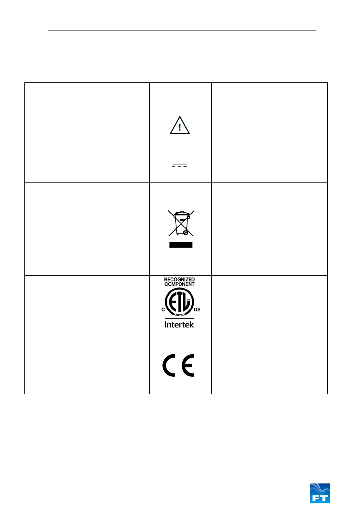
Meaning / Description
Symbol
Significantion/ Description
Warning/ Caution
An appropriate safety instruction should be
followed or caution to a potential hazard
exists
Advertisement
Une instruction de sécurité doit être
suivie ou attention portée à un danger
potentiel qui existe.
DC Current only
Equipment operates under Direct Current
(DC) supply only.
Courant Continu
L'équipement fonctionne sous une
alimentation en courant continu (CC)
uniquement.
Product Disposal
In accordance with European directive
2012/19/EU on Waste Electrical and
Electronic Equipment (WEEE), these
product components must be recycled. This
should be done by returning the product to
FT Technologies or by using an appropriate
waste disposal company. This product
should not be disposed of in general waste
or landfill.
Élimination du produit
Conformément à la directive
européenne 2012/19/EU relative aux
déchets d'équipements électriques et
électroniques (DEEE), ces composants
du produit doivent être recyclés. Cela
doit être fait par le retour du produit à FT
Technologies ou en utilisant une
entreprise d'élimination de déchets. Ce
produit ne doit pas être éliminé avec les
ordures ménagères ou en décharge.
Recognized Component
Sensors marked with the ETL label indicate
that the product conforms to UL Standard
61010-1 and is certified to CSA Standard
C22.2 No. 61010-1.
4000105
Composant Reconnu
Les capteurs marqués avec l’étiquette
ETL indiquent que le produit est
conforme à la norme UL 61010-01 et est
certifié à la norme CSA22.2 61010-01.
CE Mark
The EU Declaration of Conformity complies
with the essential requirements of the
following applicable EMC Directive
2014/30/EU, and carries the CE Marking
accordingly.
Marquage CE
Déclaration de conformité CE de la
compatibilité électromagnétique (EMC)
et marquage CE conformément à la
directive CE 2014/30/EU.
Product Symbols
The following symbols are used upon the product and throughout the manual.
3 FT702LT/D Flat Front Wind Sensor Manual
Page 4

English
To ensure the safe installation and operation of this product
The equipment must be installed and integrated;
o Using suitably qualified and trained personnel
o In accordance with any regional electrical codes
o In accordance with the instructions set out in this manual, observing all information, warnings
and instructions
o In accordance with any other instructions or guidance FT Technologies provide
To ensure that the product remain compliant with the electrical safety requirements of the UL / CSA
61010-1 standards, the equipment must be;
o Connected to an appropriately approved isolated power supply (for example UL/CSA IEC
60950-1:2005 + A1:2009 + A2:2013) rated 20-30VDC and be current limited (6A Max)
o Protected by UL 1449 Listed surge protective devices
o Connected with an approved interface cable (for example UL/CSA recognised AWM style
21198, rated 300V, 80°C)
The equipment must only be operated within the range of the specified technical data and used for the
purposes for which it was designed
The equipment should always be transported in packaging which is appropriate, that will prevent any
accidental damage from occurring.
Always ensure that any failures or errors from the product cannot cause any damage to any other
equipment or property or cause any other consequential effects.
Safety Instructions
4 FT702LT/D Flat Front Wind Sensor Manual
Page 5

Français
Pour assurer la sécurité de l'installation et le fonctionnement de ce produit
L'équipement doit être installé et intégré ;
o À l'aide de personnel qualifié et formé.
o Conformément à tous les codes électriques régionaux.
o Conformément aux instructions figurant dans ce manuel et en observant toutes les
informations, avertissements et instructions.
o Conformément à d'autres instructions ou directives que FT Technologies fournit.
Pour garantir que le produit reste compatible avec les exigences de sécurité électrique de l'UL/CSA
61010-1 normes, l'équipement doit être ;
o Connecté à une alimentation agréée convenablement isolée (par exemple UL/CSA IEC 60950-
1:2005 + A1:2009 + A2:2013) de tension nominale 20-30 VCC et avec courant limité (6 A
max).
o Protégé par des dispositifs de protection UL 1449 contre les surtensions.
o Connecté avec un câble d'interface (par exemple UL/CSA reconnu AWM style 21198, de
valeur nominale 300 V, 80°C).
L'équipement doit être utilisé uniquement dans la plage des données techniques spécifiées et utilisé
aux fins pour lesquelles il a été conçu.
L'équipement doit toujours être transporté dans un emballage qui est approprié, qui permettra d'éviter
qu'un quelconque dommage accidentel ne survienne.
En toutes circonstances, garantir que les défaillances ou les erreurs du produit ne puissent pas causer
des dommages à d'autres équipements ou autres biens ou provoquer d'autres effets indirects.
Consignes de sécurité
5 FT702LT/D Flat Front Wind Sensor Manual
Page 6
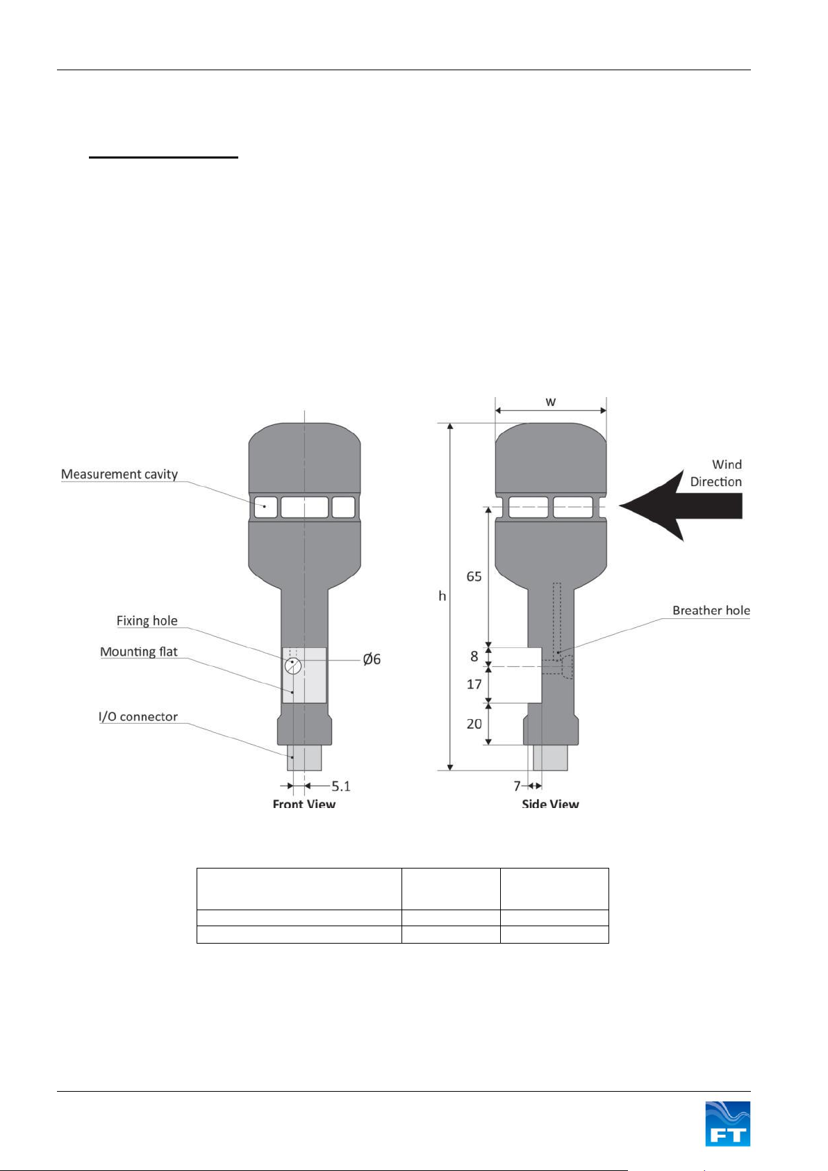
Section 1 Introduction
Maximum Sensor
Dimensions
h (mm)
w (mm)
Before build version 22
167
50
Build versions 22 and after
161
55
1 INTRODUCTION
1.1 Product Overview
The FT702LT/D is a solid-state ultrasonic wind sensor which uses a patented Acoustic Resonance airflow
sensing technique to measure accurately both wind speed and direction. The FT702LT/D has been specifically
designed to operate in harsh environments such as offshore and lightning and ice-prone areas. The wind sensor
has no moving parts to degrade or wear-out and is designed for applications requiring high reliability. The
FT702LT/D helps reduce costly down-time and unscheduled maintenance visits.
Mounting and aligning the sensor is very straightforward. The mounting flat on the sensor body defines the 0
wind datum so that the sensor automatically aligns to a reference point. For operation in ice-prone areas the
FT702LT/D is fitted with a highly effective thermostatically controlled ‘all-body’ heating system. A three element
heater (one element located in the top of the sensor and two in the bottom) is used to ensure that heat is evenly
distributed over the entire surface area.
O
Figure 1: FT702LT/D Flat Front Wind Sensor#
#
actual sensor shape varies between build versions
6 FT702LT/D Flat Front Wind Sensor Manual
Page 7
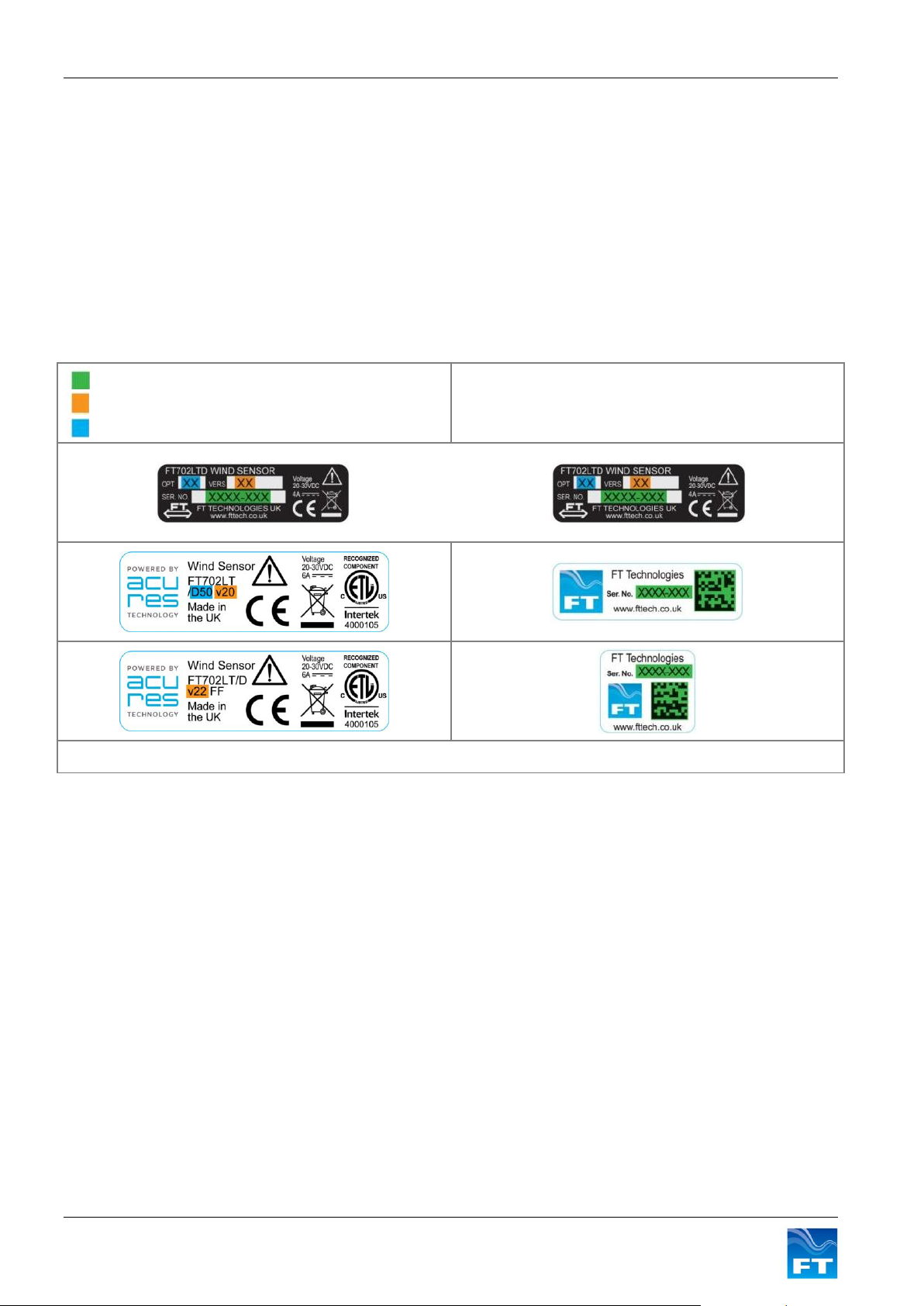
Section 1 Introduction
Serial number
Build version
Wind speed scaling reference
Product label key*
*Additional labels may also be attached. Examples of older labels are included for reference.
1.2 Build Versions and Labelling
Each time a substantial revision is made to the design of the wind sensor the build version number is
incremented. All new variants are backwards compatible with the previous build versions. Each uses the same
mounting, connector pin outs and signal characteristics and contains all the original functions.
Where a new function has been introduced the first build version to have it included is stated.
Figure 2 shows examples of how to identify an FT702LT’s build version, individual serial number and wind
speed scaling (if applicable), depending on which main label is attached. Section 2.2.2 describes how you can
use the wind speed scaling reference to identify the calibration of the sensor.
Figure 2: Examples of Main Sensor Labels
Only sensors marked with the Intertek label conform to UL 61010-1 and are certified to CAN/CSAC22.2 No.
61010-1-04. Some early build versions do not have this certification.
1.3 Pipe Mount Sensor
It is possible to mount the wind sensor directly on top of a pipe. Details of the Pipe Mount sensor and system
can be found in a separate manual. The Pipe Mount sensor offers enhanced environmental sealing, lightning
protection, thermal conductivity and corrosion resistance. The base of the Pipe Mount sensor is different to the
Flat Front sensor’s described in this manual. Please contact FT Technologies for further information.
1.4 Scope of Use
The FT702LT/D is designed, manufactured and optimised for high availability. The FT702LT/D wind sensor
often attains 99.9% or better availability of wind speed and wind direction readings.
No promise in part or full can be given to guarantee an FT702LT/D wind sensor’s continuous operation, as
exceptional circumstances can occur that may result in the failure of the output from a sensor. Exceptional
circumstances can include;
Poor installation
Inadequate inspection
Power supply failures
7 FT702LT/D Flat Front Wind Sensor Manual
Page 8

Section 1 Introduction
Poor quality electrical connections
Lightning exposure
Problematic environmental conditions or combination of conditions
Typically higher levels of wind speed and wind direction data availability are achieved through the use of an
additional FT sensor or an additional mechanical or ultrasonic sensor. Control strategies or controller
algorithms, which compensate in whole or in part, for any temporary interruption of data from individual sensors,
should also be applied. The choice and implementation of such methods is entirely the Purchaser’s
responsibility.
1.5 Disclaimer
There are no warranties, representations or conditions, expressed or implied of any kind given in this manual for
any particular design application. The Purchaser should independently undertake sufficient testing to confirm
validity and suitability of any design. The Purchaser assumes all risks and liability in conjunction with the use of
the information given.
Any warranty given by FT Technologies in respect of the Equipment is conditional upon the sensor being
handled, installed, integrated and operated in accordance within the guidelines given in this manual.
FT Technologies can take no responsibility for the effectiveness of any sensor lightning protection scheme
implemented. The wind sensor has passed a wide range of EMC tests but FT Technologies does not warrant
the sensor to survive direct lightning strikes.
Information supplied by FT Technologies Ltd. shall not be construed as permission to license to operate under,
or recommendation to infringe any existing or pending patent, patent applications or trademarks.
8 FT702LT/D Flat Front Wind Sensor Manual
Page 9

Section 2 Functional Description
2 FUNCTIONAL DESCRIPTION
2.1 Technical Performance
Sensor Performance1
Measurement Principle Acoustic Resonance, compensated against variations in temperature,
pressure and humidity
Wind speed Measurement
Range 0-50m/s
Accuracy 0.5m/s (0-15m/s), 4% (>15m/s)
Resolution 0.1m/s
Wind Direction Measurement
Range 0 to 360
Accuracy 2 (within 10 of 0 datum), 4 (beyond ±10⁰ of 0⁰ datum)
Resolution 1
Environment
Temperature Range -40 to +85C (operating and storage)
Humidity 0-100%
Data I/O
Analogue Option
Interface 4-20mA, galvanically isolated from power supply lines and case
Format One 4-20mA current loop for wind speed (see Figure 4 for scaling factors
available)
One 4-20mA current loop for wind direction (4-20mA = 0-360deg) (see
Figure 8 for offset options available)
Reading Update Rate 5 per second
4-20mA Configuration Port2 RS485 half duplex, non-isolated relative to power ground
Power Requirements4
Supply Voltage 20V to 30V DC (24V DC nominal)
Supply Current (Heater off) 30mA
Supply Current (Heater on) 6A (max)* – The heater is thermostatically controlled. Heater power
consumption will depend on the heater energy required to keep the sensor’s
temperature at a user determined set point. The heater and sensor power
consumption is limited by default to 99W3.
*Only 4A (max) power consumption possible for sensors prior to build
version 223.
Physical
Weight 320g (max)
Material Aluminium alloy, hard anodised
I/O Connector 8 way (Analogue option),
Mounting Method Self aligning, single screw fixing
Notes:
1. All specifications subject to change without notice
2. The Configuration Port is provided to allow the user to change the internal settings of the FT702LT/D and to
perform diagnostic testing. This interface should only be used for configuration and test purposes. This
interface is not intended for permanent connection to the turbine controller.
3. The heater set point and current limit can be configured by programming the sensor’s internal parameter
settings (only available from build version 22 and above)
4. See safety instruction requirements (page 4)
9 FT702LT/D Flat Front Wind Sensor Manual
Page 10
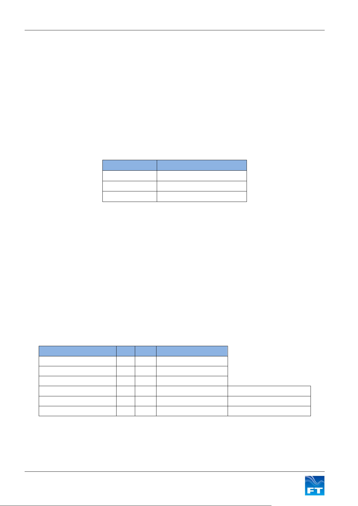
Section 2 Functional Description
Loop Supply
Maximum Loop Resistance
20V
500 Ω
24V
700 Ω
30V
1000 Ω
Wind Speed Scaling references
4mA
20mA
Scaling Factor (mA per m/s)
30
0m/s
30m/s
0.5333
40
0m/s
40m/s
0.4000
50
0m/s
50m/s
0.3200
60
0m/s
60m/s
0.2666
output limited to 17.33mA (50m/s)
70
0m/s
70m/s
0.2286
output limited to 15.43mA (50m/s)
Custom
0m/s
XX
Variable
Only available from build version 22
2.2 Current Loops
2.2.1 Current Loop Characteristics
The FT702LT/D wind sensor incorporates two galvanically isolated 4-20mA current loop outputs, one loop for
wind speed and one loop for wind direction. These current loop outputs can be converted into measurable
output voltages with the addition of external resistors.
Each loop should be powered from a DC supply in the range 20V to 30V. A positive supply must be provided to
one of the current loop wires. The other wire must then be connected through a current meter to ground. This is
because the FT702LT/D current loops sink current, they do not source it. A common supply can be used if
required. Loop connections are polarity insensitive so that the +ve or –ve loop supply connection can be made
to either of the current loop connection pins. See example wiring in Figure 21.
The current loops are able to operate over long cable distances; however the overall loop resistance should not
exceed the values given in Figure 3. It is recommended that twisted pair interconnection cabling should be
used. The cable should also include an overall braided screen.
Figure 3: Maximum Current Loop Resistance
The wind sensor’s current loop outputs are updated at a rate of 5 times per second. An average of several
readings should always be used for any calculations or control decisions because single readings can
accidentally become corrupted (see section 2.2.5).
The sensor has its own internal filtering enabled by default, which dampens the speed and wind direction
outputs by averaging the previous 1.6 seconds of data. It is possible to disabled the internal filter (however not
recommended) by using the FT702LT/D Set-Up and Test Program (See Section 4 and 5).
2.2.2 Wind Speed Loop
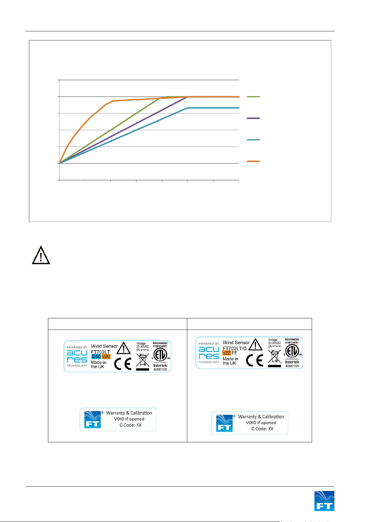
The default wind speed scaling is such that a change from 4 to 20mA represents 0m/s-50m/s. This corresponds
to a scaling factor of 0.32mA per m/s. The measurement scaling factor for the wind speed current loop is set at
the factory. Figure 4 shows the wind speed calibrations that are available.
The models with scaling factors above 50m/s are intended for applications such as wind turbine controllers
where the wind speed scaling is preset and cannot easily be changed. Because the maximum wind speed
range of the FT702LT/D is 50m/s for models with full scale settings above 50m/s the maximum output current is
limited to a value equivalent to 50m/s (see Figure 4).
From build version 22 the wind speed loop can also be calibrated with non-linear scaling functions. See
example customisable calibration in Figure 5.
10 FT702LT/D Flat Front Wind Sensor Manual
Figure 4: Wind Speed Scaling Factors
Page 11
Section 2 Functional Description
If a wind sensor is replaced care must be taken to ensure that the 2 sensors have the same
calibration. Otherwise the system processing the wind data might perform differently after the
sensors are swapped
V20 - Standard 0-50m/s = 4-20mA. = Default
V22 - All other calibrations
The wind speed scaling reference is shown on
the part number label as 50
The C-Code:01 label is sometimes also
attached
No wind speed scaling reference is shown
on the part number label
The additional C-Code label and number
XX is used to identify the type of
calibration applied
0
4
8
12
16
20
24
0 10 20 30 40 50 60 70
Current Loop Output (mA)
Wind Speed (m/s)
Wind Speed Current Loop Output Calibration Examples
0-40 m/s
0-50 m/s = Factory Default
0-60 m/s
Customisable calibration
Only from build version 22
Figure 5: Wind speed output calibrations
The wind speed scaling reference given on the main product labels can be used to identify the wind speed
calibration of the sensor. (See section 1.2).
From build version 22 and above a C:Code label might be attached. The C:Code number then indicates the type
of calibration applied. 2 examples are shown in Figure 6.
11 FT702LT/D Flat Front Wind Sensor Manual
Figure 6: Build version 22 sensor calibration label examples
Page 12
Section 2 Functional Description
180 225 270 315 0 45 90 135 180
2.2.3 Wind Direction Loop
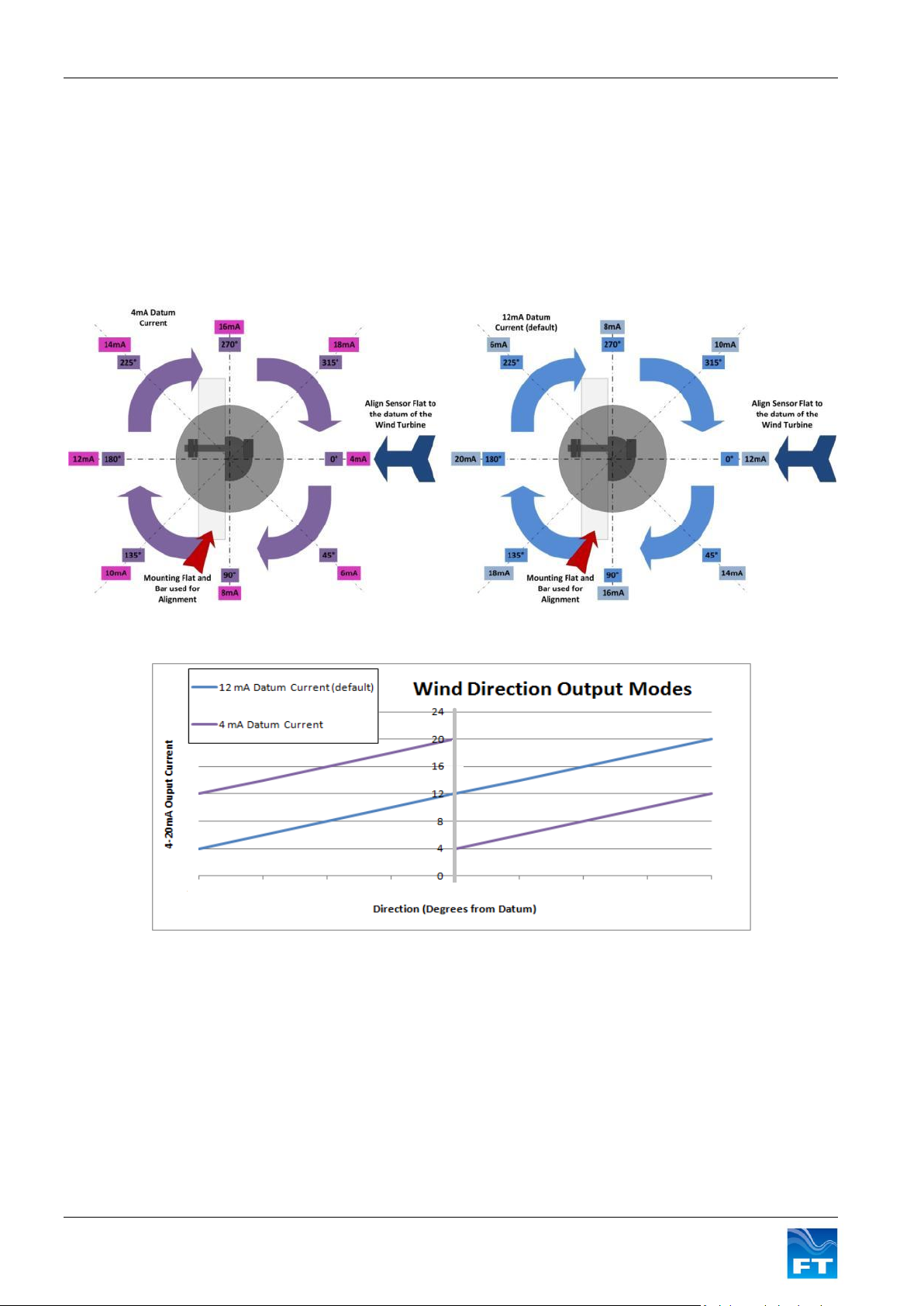
The wind direction scaling is such that a change from 4 to 20mA represents 360 degrees (with no dead band)
which corresponds to a scaling factor of 0.0444mA per degree.
The FT702LT/D measures the wind direction relative to the 0 degree datum. The 0 degrees datum location for
the FT702LT/D is shown in Figure 7.
The default setting for the current loop output when the wind is blowing towards the datum direction is 12mA. If
required, the direction loop can be set to give an output of 4mA at the datum direction. The output options are
shown in Figure 8.
Figure 7: Visualisation of direction with 4mA and 12mA current offsets
Figure 8: Comparison of wind direction current offsets
When operating in the 4mA datum current mode there is a 16mA transition each time the wind direction crosses
the datum. In the 12mA datum current mode the output current varies linearly about the 12mA value as the wind
direction moves around the datum.
2.2.4 Changing the wind datum direction
The datum direction can be electronically rotated (either clockwise or counter clockwise) in 1 deg increments
using the FT702LT/D Set Up and Test Program (see section 5) to apply this adjustment. Once the datum offset
has been set it will be retained in the FT702LT/D Flash memory.
12 FT702LT/D Flat Front Wind Sensor Manual
Page 13
Section 2 Functional Description
Always use an average of several readings for any calculations or control decisions because
single readings can accidentally become corrupted.
2.2.5 Error Detection
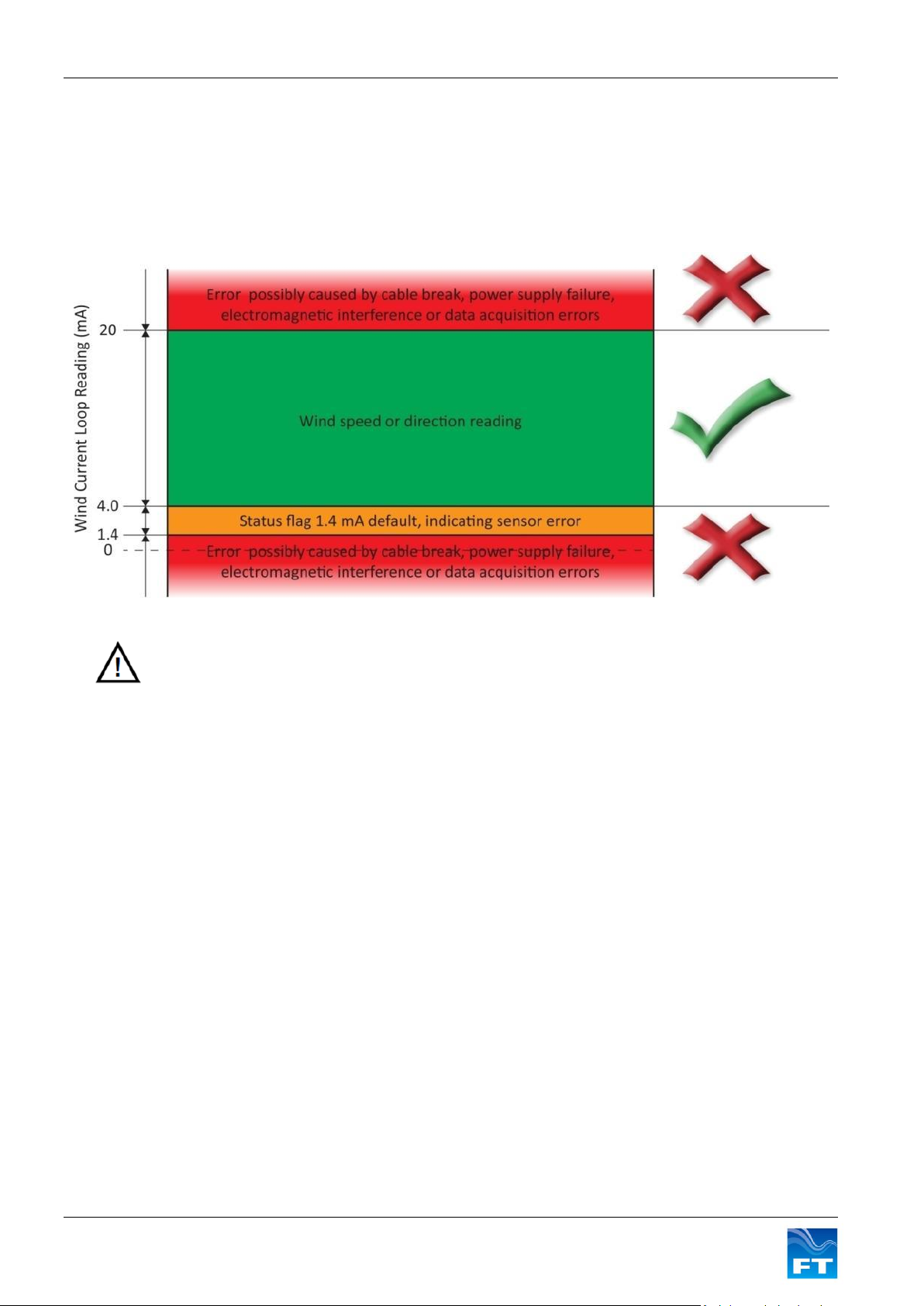
If the FT702LT/D detects that a reading may be invalid this is signalled to the controller or data logger by setting
the current of both loops to a value of 1.4mA by default. The error current level can be configured (see Section 5)
by the user from 1.4mA up to 3.9mA in steps of 0.1mA (only available from build version 22 and above).
The error condition must occur for more than 1 second for the current loops to be set to this condition. If an error
occurs for less than 1 second then the loop outputs will be held at the last valid reading for the duration of the
error.
Figure 9: 4-20mA valid readings range
The data acquisition system needs to not only sample the 4-20mA measurement range, but also should include
logic to process and exclude data if it is outside the measurement range. The data acquisition system should
distinguish between a status flag error sent by the wind sensor and other out of range readings in order to help
diagnose if a fault has occurred with the power supply, cable or wind sensor.
2.3 Heater Setup
The FT702LT/D is fitted with an integral three element distributed heater that can be used to prevent icing-up of
the sensor in freezing temperatures. The heater is controlled automatically by the FT702LT/D using a user
programmable ‘set point’ temperature. The FT702LT/D uses a control scheme which dynamically changes the
current supplied to each individual heater to maintain the programmed set point temperature.
It is important to consider the resistive losses in the cable and rate the cable appropriately. In general, power
losses in the cable should be minimised in order to maximise the available heating power to the sensor.
The factory default setting for the heater set point value is 30° C. This is the recommended setting for most
applications. To change the heater set point or to disable the heater use the FT702LT/D Set Up and Test
Program (see section 5).
Since the heater circuit is thermostatically controlled the actual power being drawn from the supply will depend
on the programmed set point and the prevailing environmental conditions (i.e. ambient temperature, wind
speed, precipitation etc). The maximum power that the FT702LT/D heater and sensor can consume is by
default limited to 99W. The power supply must be rated to provide the maximum power that the sensor can
consume.
From build version 22 and above the maximum current limit of the sensor can be adjusted in software from 0.1 –
6 Amps. To change the current limit use the FT702LT/D Set Up and Test Program (see section 5).
From build version 22 and above the sensor can detect when the supply voltage drops below 9 VDC, when this
occurs the heaters are automatically switched off.
13 FT702LT/D Flat Front Wind Sensor Manual
Page 14
Section 3 Installation
See safety instruction requirements on page 4.
The wind sensor installation must be properly designed to ensure the correct
operation of the sensor. This section is for guidance only. It is the responsibility of the
designer and installer to ensure that the installation and its design is fit for purpose.
Please see disclaimer section 1.5.
Connector Type
Connector
Description
Manufacturers Part Number
FT Sensor
Type
Maximum Outer
Cable Diameter
Manufacturer
FT702LT/D
Cable Side
Connector
8 way plug
SS104Z129-1
FT702LT/D
Analogue
Option
8.0mm
W.W.Fischer
FT702LT/D
Cable Side
Connector
8 way plug
SX2F1C-P08NJH9-0001
FT702LT/D
Analogue
Option
9.2mm
ODU
3 INSTALLATION
3.1 Connectivity
3.1.1 Connector Details
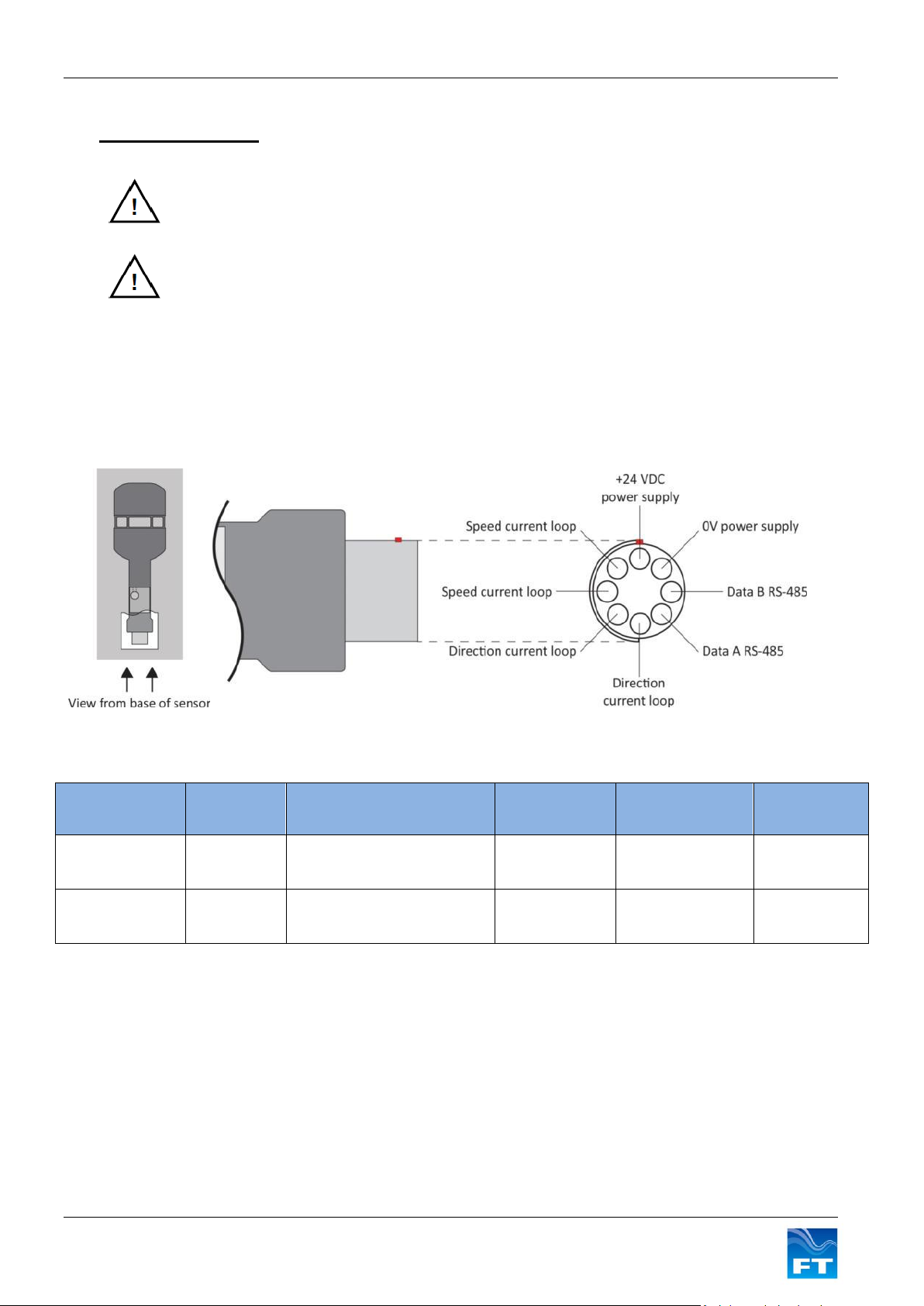
All electrical connections are made to the FT702LT/D via an 8-way multipole connector located in the base of
the wind sensor housing. The wind sensor connector pin designations are shown in Figure 10 and the mating
connector manufacturer’s part numbers in Figure 11.
Figure 10: Sensor connector pin out
Figure 11: Cable Connector Sourcing Options
3.1.2 Cable Details
The mating connectors for the FT702LT/D are suitable for use with cables with overall diameters of up to 9mm
and for individual cores of diameters of up to 1.2mm. Cable such as SD980CPTP 3x2x0.5mm2 from SAB
Brockskes or similar types may be used. Care must be taken to ensure that the cable is suitable for the
environment it will be used in and is adequately approved, for example AWM Style 21198.
In an area with a moderate or severe lightning strike exposure the cable shield will not provide sufficient
protection. In this case the cable will require further shielding such as being enclosed in a metal pipe or conduit
(see section 3.3).
14 FT702LT/D Flat Front Wind Sensor Manual
Page 15
Section 3 Installation
3.2 Mounting the FT702LT/D
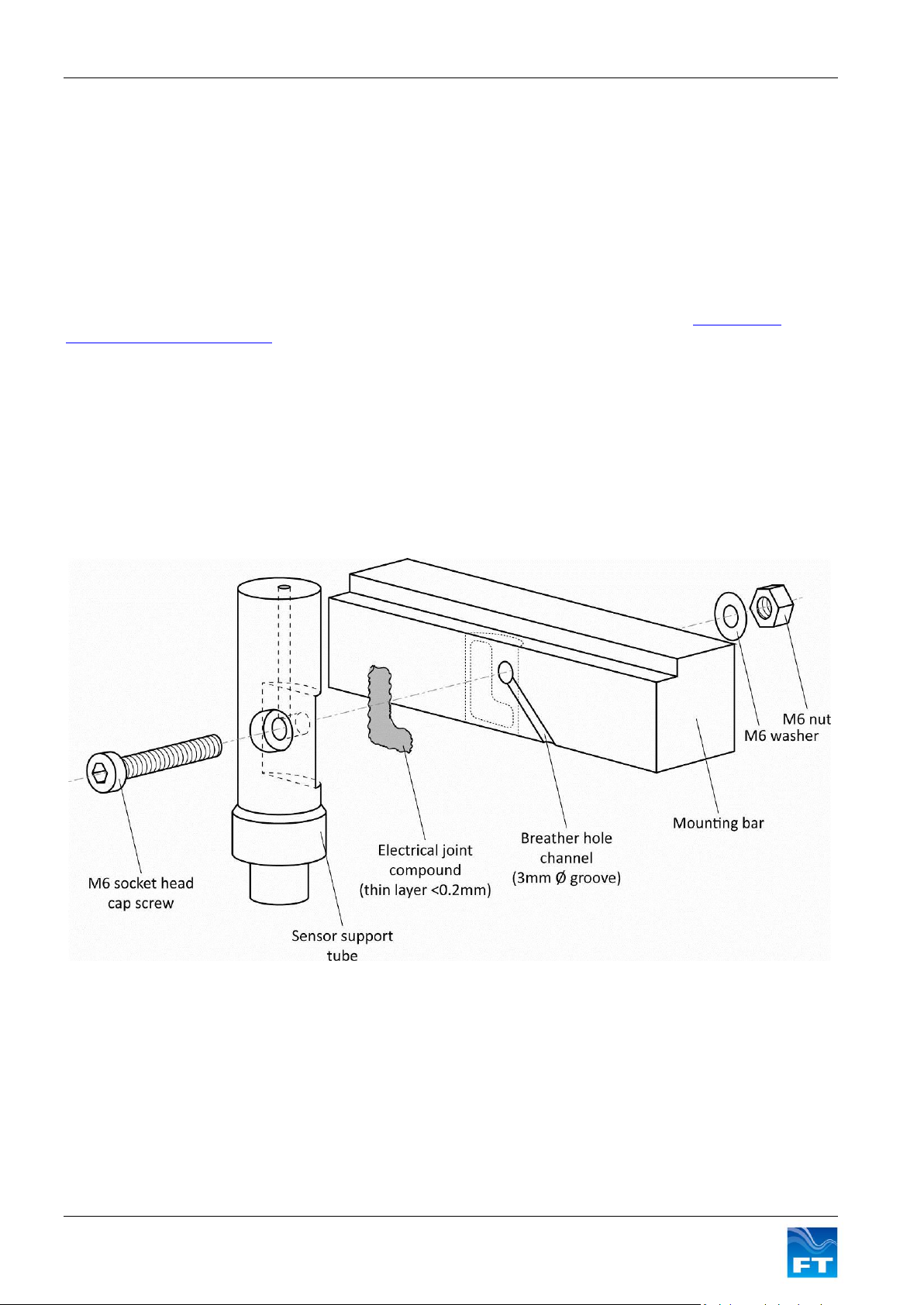
The FT702LT/D is designed to be mounted using an M6 socket head cap screw, nut and washer. The mounting
flat on the support tube of the sensor (see Figure 1) allows for firm fitting against a flat surface. The preferred
finish of the screw, nut, washer and the mounting bar is hot dipped galvanised steel. The mounting bar should
have a minimum galvanising thickness of 50µm to ensure long-term protection against corrosion. The
galvanising quality should conform to ASTM A123, Standard Specification for Zinc (Hot-Dip Galvanised)
Coatings on Iron & Steel Products. Aluminium components of the appropriate grade could be used as an
alternative.
The mounting flat is provided free of coatings to allow for a good electrical connection between the body of the
sensor and ground through the mounting bar. In order to protect the mounting flat against corrosion, a very thin
layer (<0.2mm) of electrical joint compound should be applied. An example of this could be AFL Global’s
Electrical Joint Compound # 2. It should be applied directly to the sensor’s mounting flat, whilst avoiding the
fixing hole. Use of an electrical joint compound will also help to maintain long-term low impedance connection to
ground. This connection should be checked as part of the annual inspection of the sensor as detailed in Section
3.4.
Some electrical joint compounds contain fluoride etchants which may react with certain materials. Material
compatibility should therefore be checked prior to application (refer to the electrical joint compound
manufacturer’s data).
In order to keep the pressure within the sensor equalised with the atmospheric pressure, a small breather hole
is located within its support tube. It is therefore important that the airway to this breather hole be kept clear. This
can be achievable by cutting a small 3mm channel in the mounting bar as shown (see Figure 12).
Figure 12: Sensor Installation
It is recommended that a protective sleeve be fitted over the base of the sensor and the connector. This will
provide environmental protection as well as stress-relief from vibration. Heat shrink or cold shrink would be
suitable for this purpose. FT offer a cold shrink solution which is available on request (part number FT909). The
sleeve should cover the lower part of the support tube; the connector itself and at least 25mm of cable (see
Figure 13).
15 FT702LT/D Flat Front Wind Sensor Manual
Page 16
Section 3 Installation
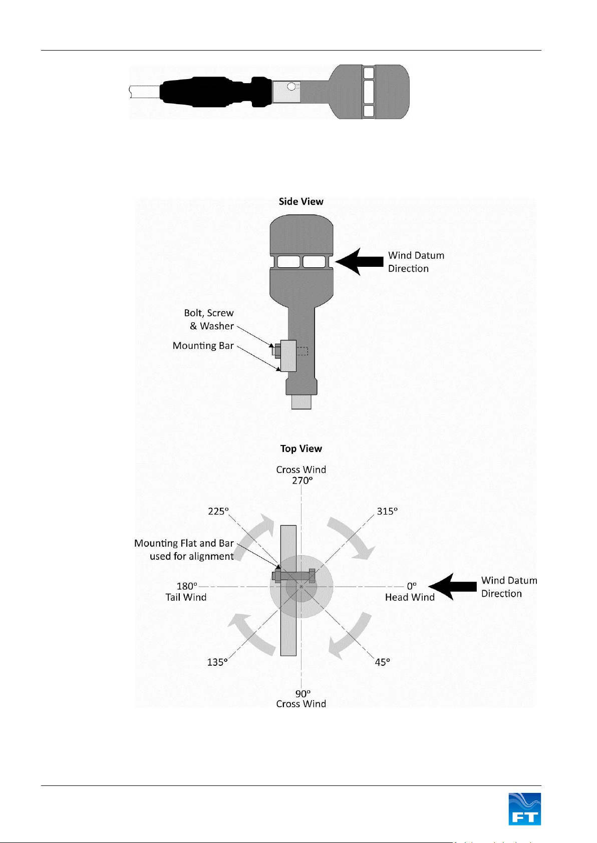
Figure 13: FT702LT/D-FF with protective sleeve
3.2.1 Alignment
The FT702LT/D measures the wind direction relative to the mounting flat and bar. When the wind sensor is
correctly aligned the wind direction measurements will be as shown in Figure 14.
Figure 14: Correct Sensor Alignment
16 FT702LT/D Flat Front Wind Sensor Manual
Page 17
Section 3 Installation
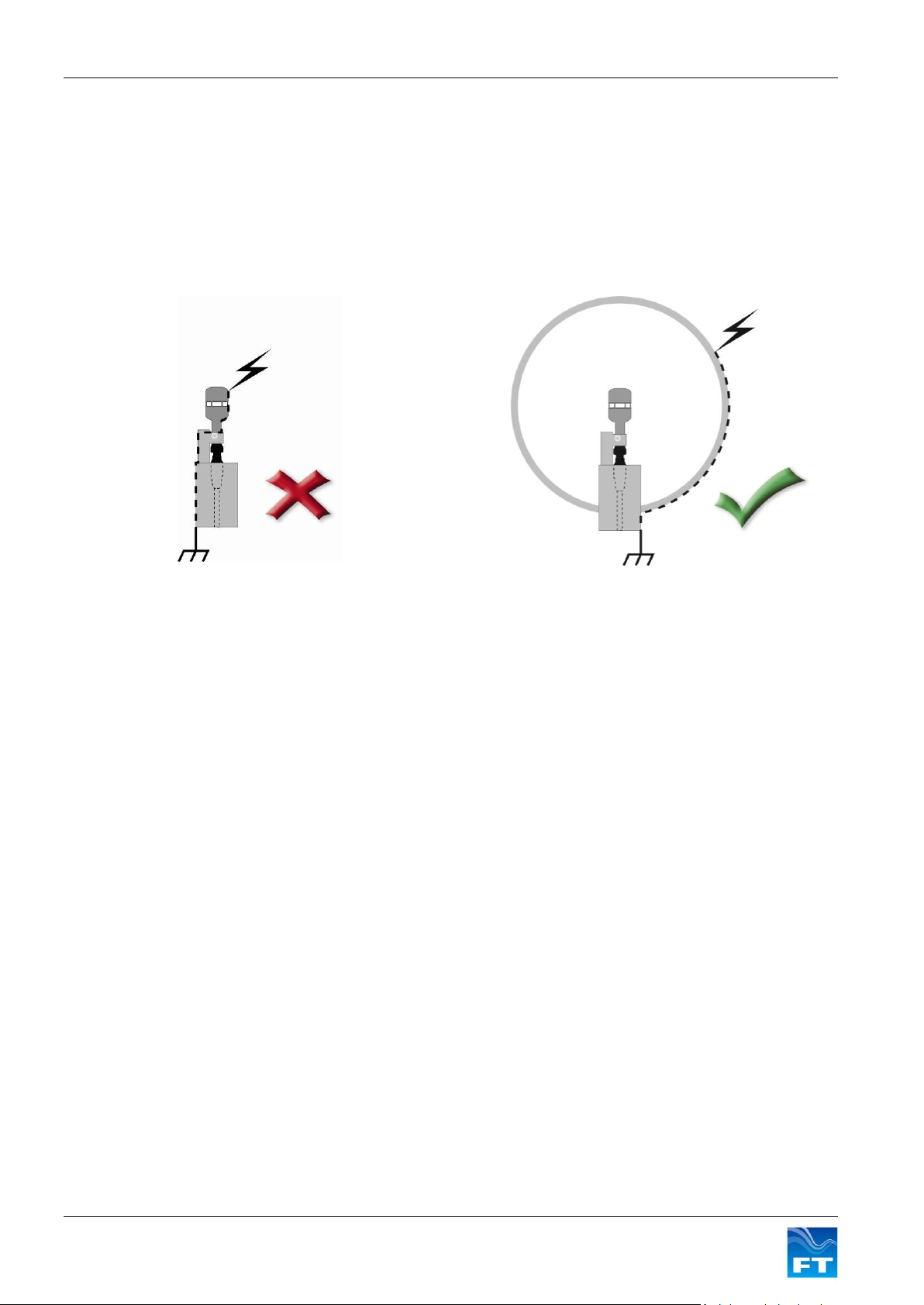
Figure 15: Direct lightning strike
Figure 16: Indirect lightning strike
3.3 Lightning protection and EMC
It is important to install the sensor with appropriate protection against lightning and other sources of
electromagnetic interference in order to maximise its chance of survival and continued operation during and
after exposure.
3.3.1 Protection against direct lightning effects
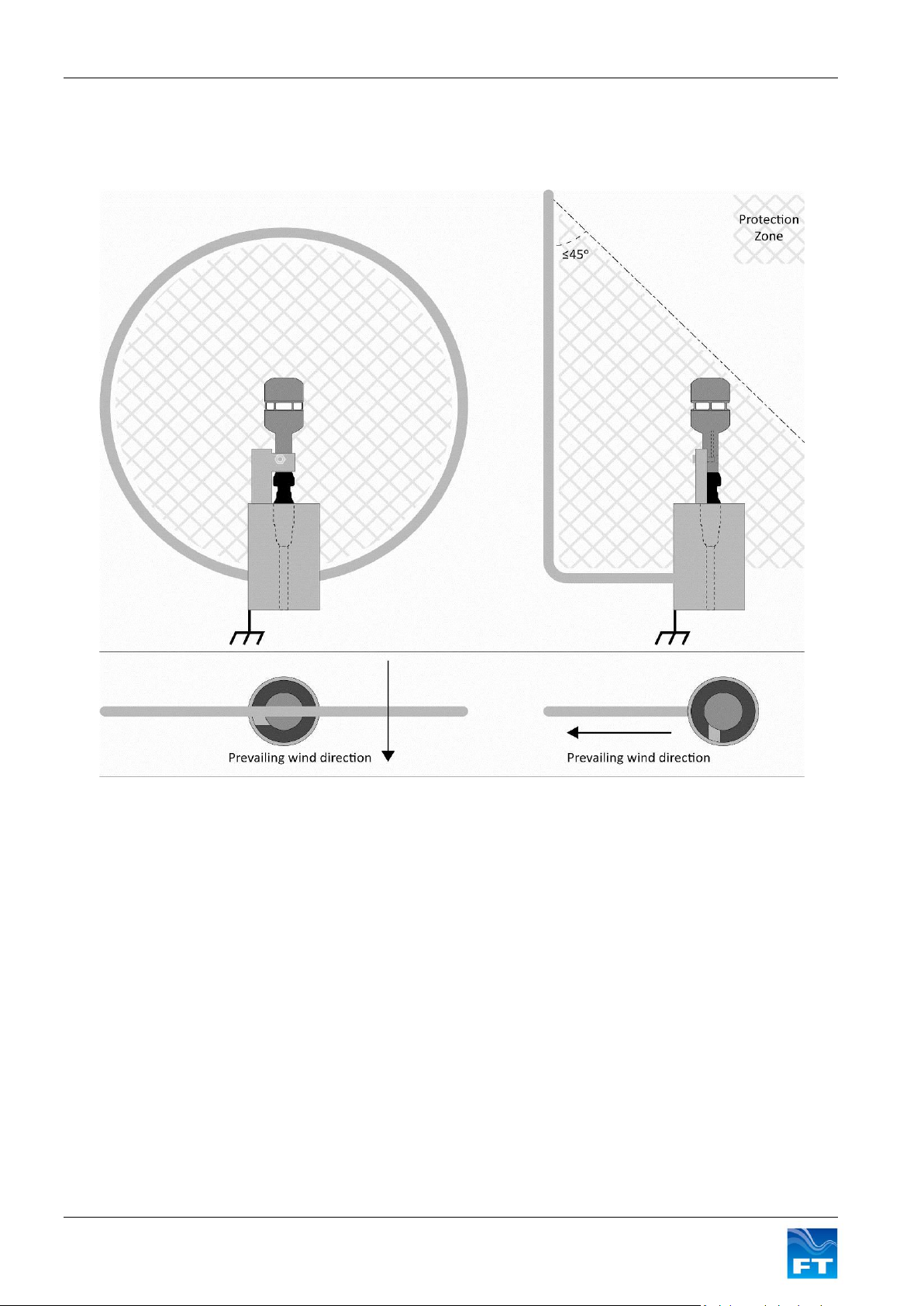
The sensor installation must be designed in such a way that a protection zone is created around the sensor so
that its body can never be subjected to a direct lightning strike.
This level of protection is achievable through the use of conductive structural parts known as “lightning
interceptors”. These help to create the protection zone and to divert the majority of the lightning current away to
ground.
The lightning interceptor must have a direct connection to ground through metal parts with a minimum crosssectional area of 50mm2 (see Figure 19). The length of any grounding wire or strap must be kept to a minimum.
This will help to provide the lowest possible impedance path to the ground reference.
17 FT702LT/D Flat Front Wind Sensor Manual
Page 18
Section 3 Installation
Figure 17 below shows examples of lightning interceptors* and how they can be used to create a protection
zone around the sensor. It is recommended that the interceptor is made from hot dipped galvanised steel or
aluminium in order to prevent corrosion. This will ensure a long-term low impedance connection to ground.
Figure 17: Ring and Rod interceptors
*The standards for Lightning Protection of Wind Turbines are described in IEC 61400-24. The installation
instructions in this manual should be sufficient to ensure that the lightning protection zone around the sensor will
achieve a lightning protection level of LPZ0B as described in the standard.
18 FT702LT/D Flat Front Wind Sensor Manual
Page 19
Section 3 Installation
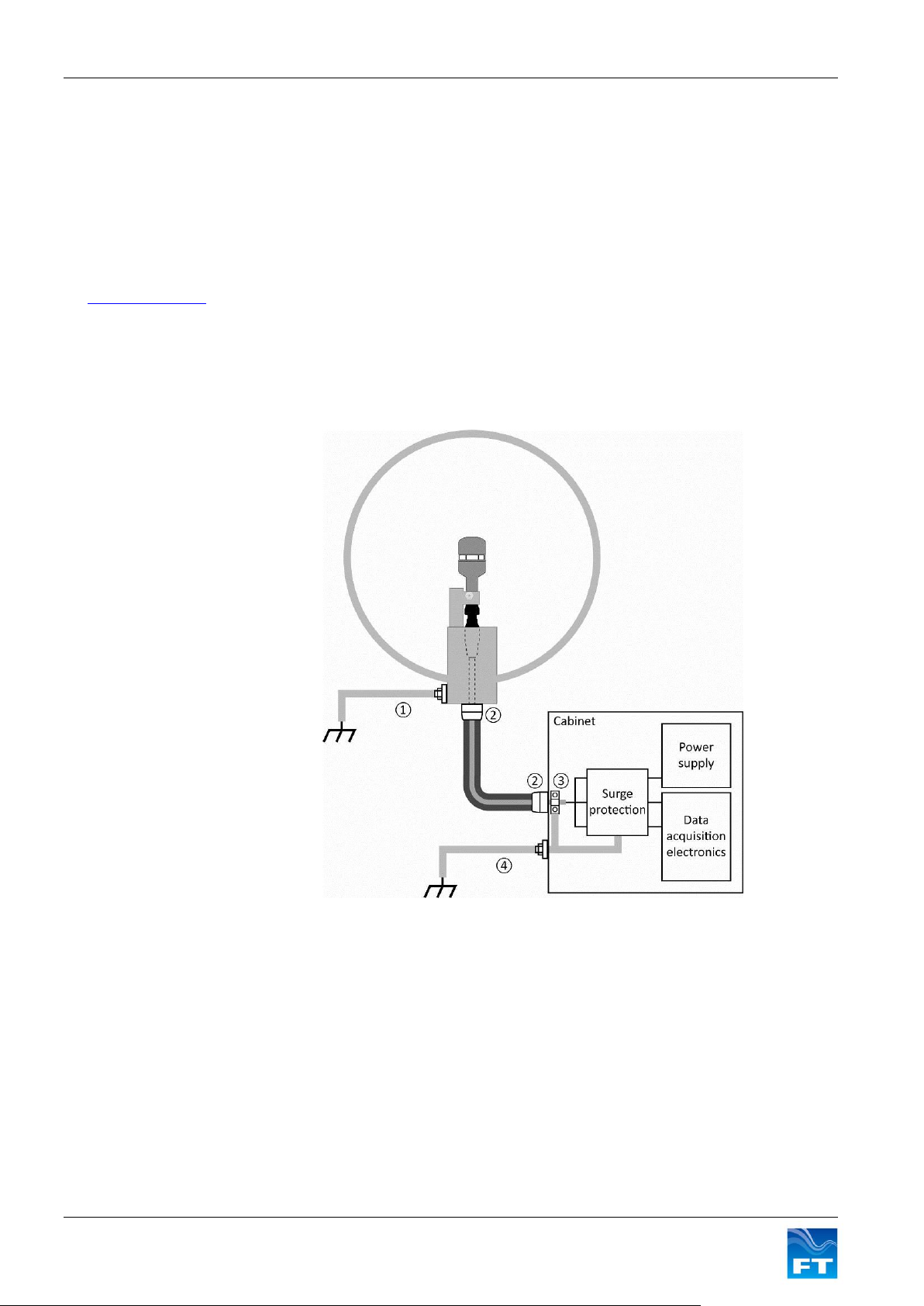
① Preferably this
connection is established
using structural steel
parts or alternatively by
use of a copper cable
with a cross section of
min. 50mm
2
② Any shielding conduit
must be terminated at
both ends
③ Shielded cable must
either be terminated
using an EMC cable
gland in the cabinet wall or alternatively using a
cable clamp in direct
connection with the
cabinet chassis
④ The chassis of the
cabinet must have a
direct connection to
ground
3.3.2 Protection against indirect lightning effects and electromagnetic interference
Objects within the protection zone described above can still be subject to very high electromagnetic field and
partial lightning surge currents. It is therefore critical that appropriate shielding and termination is used
throughout the system to reduce these effects. A shielded signal cable will offer some protection however it is
recommended that double shielding is employed between the sensor and the chassis of the data acquisition
and power supply cabinet.
A metal conduit surrounding the shielded cable is a good way of providing this additional protection and will also
help to prolong the life of cables and connectors. The impedance of this metal conduit needs to be as low as
possible since a substantial proportion of the lightning current will flow in it. An example of metal conduit could
be HellermannTyton’s HelaGuard steel conduit with plastic coating and steel overbraid.
All cable shielding must be continuous and terminated at both ends using EMC glands or cable clamps with a
direct connection to the cabinet chassis. There must also be a direct connection from the cabinet chassis to the
grounding reference. Any metal conduit used must also be continuous and terminated at both ends with
appropriate fittings. Figure 18 below shows the principle of the protection scheme.
3.3.3 Surge protection
All connections from the wind sensor to any data acquisition equipment and power supply should run through
Surge Protection Devices (SPDs). This will suppress any unwanted overvoltage transients present on the signal
or power lines. The surge suppression devices are to be UL 1449 listed.
The ratings of the SPDs must be suitable for the surge conditions. Assuming that appropriate shielding and
termination has been used throughout, then the SPDs used with our sensor should have a minimum surge
current rating of 20kA (8/20µs) and be capable of clamping the output below the maximum input voltage
accepted by the electronic systems they are connected to. This will prevent any surges or large voltage
differences being present at the inputs to the wind sensor, data acquisition electronics or power supply.
19 FT702LT/D Flat Front Wind Sensor Manual
Figure 18: Protection of equipment against indirect effects
Page 20
Section 3 Installation
Manufacturer
Type
Manufacturers part number
PSU lines
Phoenix Contact
Surge protection plug (x1)
2819008 PT PE/S+1X2-24-ST
Base element (x1)
2856265 PT PE/S+1X2-BE
Current Loop Lines
Phoenix Contact
Surge protection plug (x2)
2856058 PT 1x2-24AC-ST
Base element (x2)
2856113 PT 1x2-BE
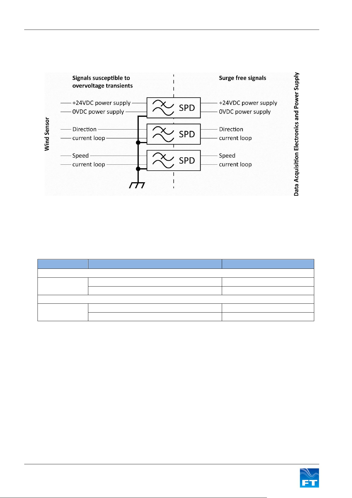
The SPDs should be installed as close as possible to the point where the signals enter the cabinet in order to
prevent noise propagating to other electronics. The SPDs should also be grounded appropriately. Figure 19
shows how the SPDs should be installed.
Figure 19: FT702LT/D analogue interface surge protection
The supply pair [24VDC / 0VDC] is electrically isolated from the other lines and the chassis. The four current
loop signals are isolated from the power supply lines and the chassis. An example of SPD suitable for this
protection can be sourced from Phoenix Contact as shown in Figure 20 below. Users are responsible for
ensuring the suitability of these components for their application.
Figure 20: Typical SPD configuration used to protect sensor
20 FT702LT/D Flat Front Wind Sensor Manual
Page 21
Section 3 Installation
3.4 Inspection of the FT702LT/D
The following checks are required to identify any signs of corrosion or damage on the sensor which may hinder
its performance. It is recommended that these checks be carried out annually.
Mechanical damage; Check the sensor body for signs of damage, paying particular attention to the seals. Also
inspect for signs of lightning damage which may appear as burns or scorch marks (or burnt smells). If damage
has occurred replace the sensor immediately.
Corrosion; Inspect the sensor’s mounting flat and the mounting bar it is fixed to for signs of corrosion. If
corrosion is present on either surface, it should be removed using an abrasive cloth. Before reinstalling the
sensor, electrical joint compound should be applied to the sensor’s mounting flat (see section 3.2). Check that
the mounting screw, nut and washer are in good condition with no signs of corrosion and tighten as necessary.
If corrosion is present replace with parts of the appropriate finish (see section 3.2).
Interconnection cable; Inspect the condition of the cable. If any part has become frayed or damaged in any
way, it should be replaced immediately. Intermittent cable faults may not be visible, but may show up as errors
in data. See section 2.2.4 for details on how to identify such faults.
Connector protective sleeve; Check for any signs of damage or degradation. If the sleeve is damaged it
should be replaced (see section 3.2).
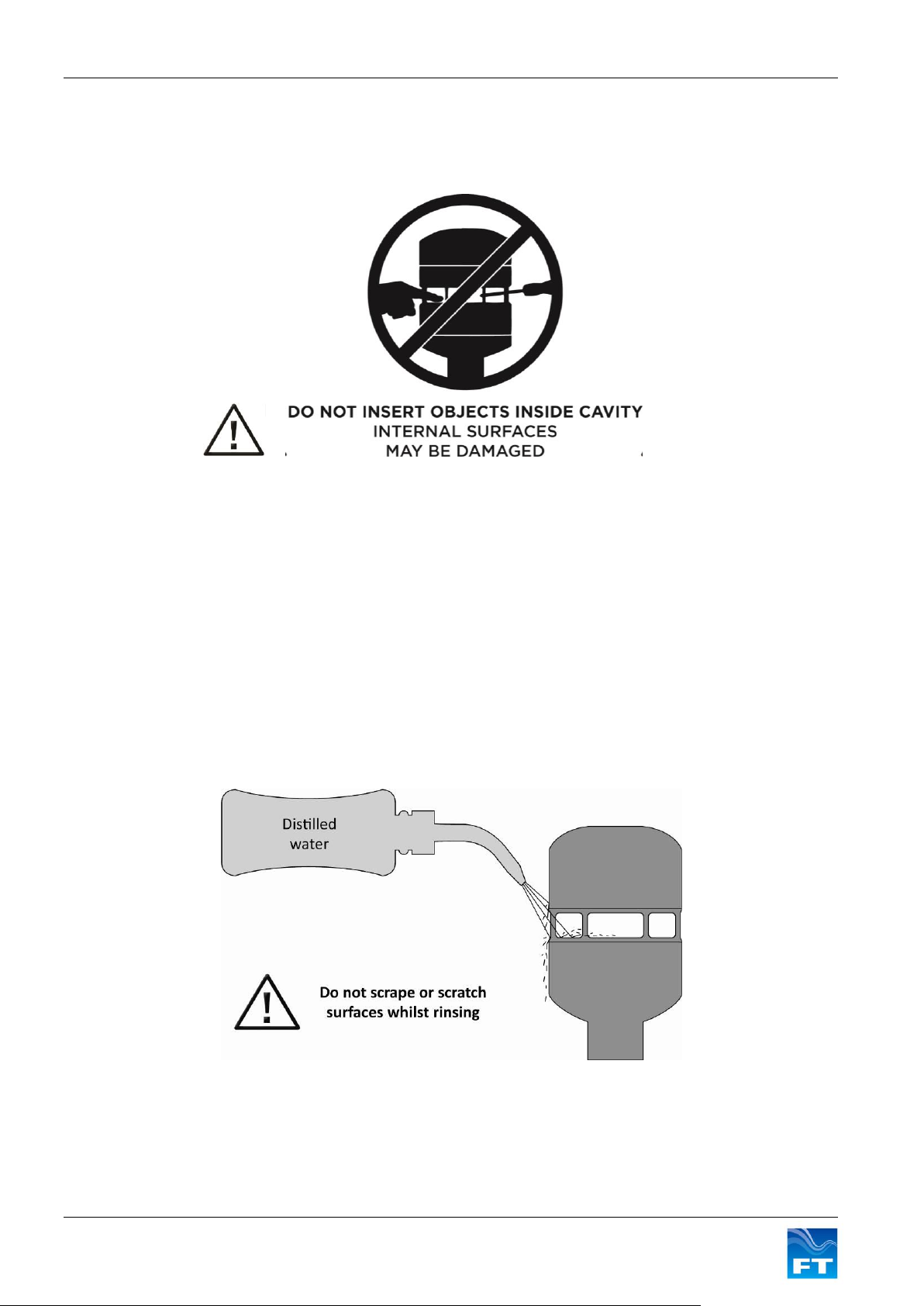
Cleaning; the measurement cavity has a special coating which helps to prevent water building up. When water
enters the measurement cavity the surface helps to wash away dust and debris which may have settled. If any
debris is present this can be removed by gently rinsing the measurement cavity surface with distilled water
using a laboratory wash bottle or similar. Please note excess water droplets can be removed by lightly blowing
or shaking the sensor.
21 FT702LT/D Flat Front Wind Sensor Manual
Page 22
Section 3 Installation
Warning – do not attempt disassembly as damage may result and product warranties will be
invalidated.
Do not use cleaning chemicals to clean the sensor. If washing a nearby item protect the sensor with a suitable
cover. Ensure the cover is removed before re-enabling the wind data survey.
Do not scrape or scratch the surfaces whilst rinsing. Under no circumstances should objects be inserted
inside the measurement cavity as this can cause irreparable damage. If the coating has been damaged then it
may need to be reapplied. The body of the sensor can be washed if required using the same method as
described above. Whilst washing the sensor care must be taken not to get water in the breather hole or into the
connector at the base of the sensor.
3.5 Fault Finding & Troubleshooting
To determine whether a sensor has a fault carry out the following steps;
Follow the inspection procedure above to identify signs of physical damage
Test that the sensor is communicating properly using the Evaluation Pack (see section 4.1)
If there are signs of physical damage and/or the sensor is failing to communicate properly, it should be
replaced. Sensors may be returned to FT Technologies for further analysis if required (see section 3.6).
If there are no signs of physical damage or problems with communication but sensor downtime or incorrect
readings have been intermittently recorded, the following steps should be taken to ensure the highest levels of
data availability from the sensor:
Using the Evaluation Pack (see sections 4 & 5):
- Check that the sensor has the latest version of software (please contact FT Technologies for
more information on latest software releases)
- Check that the heater set point is at least 30°C (see section 2.3)
- Ensure that the internal filtering in the sensor is enabled (see section 2.2.1)
Check that the wind sensor data and status flag errors are being processed in accordance with
guidelines in section 2.2.1 and 2.2.5.
Ensure the sensor has been installed with adequate lightning and EMC protection (see section 3.3)
Check that the measurement cavity’s special coating is in a satisfactory condition (see section 3.4)
Use the highest build version available as this may have features which resolve the specific problem
being experienced
Please contact FT Technologies for further information and advice if required.
3.6 Returns
If a sensor appears to be faulty, please contact FT Technologies and request a Returns Materials Authorisation
(RMA) form. Please complete the form and return as instructed. Returns cannot be accepted without prior
approval via this authorisation form.
22 FT702LT/D Flat Front Wind Sensor Manual
Page 23
Section 4 Evaluation
4 EVALUATION
4.1 Evaluation Pack
To help users carry out a test bench assessment of the FT702LT/D FT Technologies sells an Evaluation Pack.
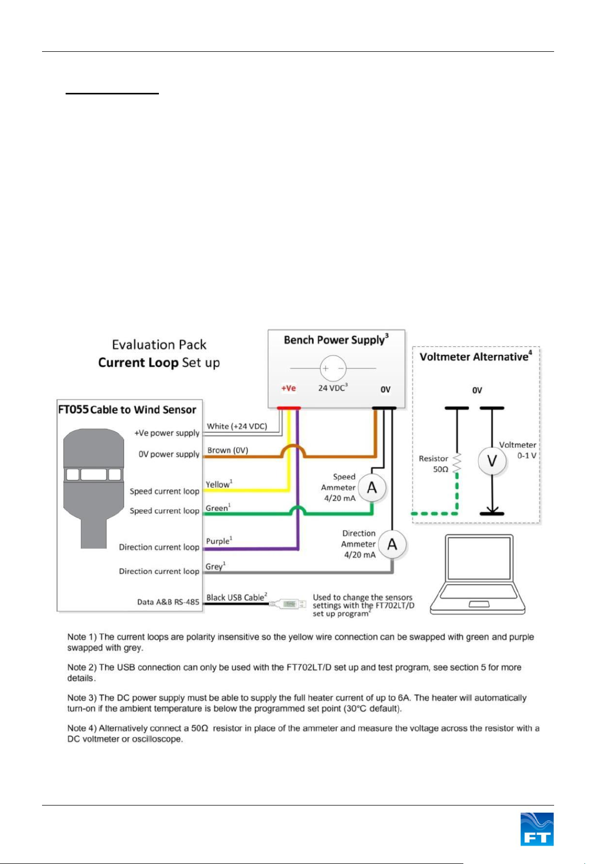
The Evaluation Pack includes the FT055 cable to connect the sensor to an external power supply. The cable is
also fitted with a USB connector to connect the wind sensor directly to a computer so that its settings can be
checked and configured. There are also colour coded wires allowing the current loops to be measured with a
multimeter or oscilloscope. (See Figure 21)
The pack also includes the FT702LT/D Set-Up and Test Program for changing a sensor’s settings (see section
5).
4.2 Wiring Diagrams
The FT702LT/D can be easily tested by connecting a DC ammeter in series with each current loop. A positive
supply must be provided to one of the current loop wires. The other wire must then be connected through an
ammeter to ground. This is because the FT702LT/D current loops sink current, they do not source it. Figure 21
shows how the Evaluation Pack can be quickly set up to evaluate the current loops.
Figure 21: Evaluation Pack Current Loop Set Up
23 FT702LT/D Flat Front Wind Sensor Manual
Page 24

Section 4 Evaluation
4.3 Quick Start Steps
1. Remove the FT702LT/D sensor and FT055 cable from its packaging and mate the connectors together.
2. Connect the +24 VDC terminal of the power supply (current limit set to 6A) to the white wire and 0V
terminal to the brown wire.
3. Connect the yellow wire (wind speed 4-20mA output) to the +24 VDC terminal on the power supply.
4. Connect the green wire (wind speed 4-20mA output) to an ammeter and then connect the other terminal
on the ammeter to the 0V terminal on the DC power supply.
5. Connect the purple wire (wind direction 4-20mA output) to the +24 VDC terminal on the power supply.
6. Connect the grey wire (wind direction 4-20mA output) to an ammeter and then connect the other
terminal on the ammeter to the 0V terminal on the DC power supply.
7. Switch on the power supply and then monitor the air flow measured on the ammeter outputs.
24 FT702LT/D Flat Front Wind Sensor Manual
Page 25
Section 5 Changing Settings
Function
Factory Default Setting
Range
Description
Heater Set Point
30° C
0-55°C & Off^
See Section 2.3
Heater Current Limit
4A
0.1-6.0A*#
See Section 2.3
Wind Velocity Filter
On
On or Off
See Section 2.2.1
Datum Offset
0°
±180°
See Section 2.2.4
Datum Current
12mA
4mA or 12mA
See Section 0
Loop Error Signal
1.4mA
1.4-3.9 mA*
See Section 0
5 CHANGING SETTINGS
The FT702LT/D is fitted with a 2 wire serial interface. This interface is provided to allow the user to change the
internal settings of the FT702LT/D and to perform diagnostic testing. This interface should only be used for
configuration and test purposes. This interface does not include the same level of lightning and EMC protection
as the 4-20mA outputs and power supply connections. It should not be permanently connected to the data
acquisitions system.
The interface should only be accessed using the FT055 cable and FT702LT/D Set-Up and Test Program
provided with the FT702LT/D Evaluation Pack (see Section 4 also). Figure 22 lists the settings that can be
modified.
Figure 22: FT702LT/D Configurable Settings
Notes:
^ Set Point above 440C only available from build version 22
* Setting only adjustable from build version 22
# Greater than 4A only available from build version 22
In addition to being able to change these settings the FT702LT/D Set-Up and Test Program is also used to run
the current loop auto-increment test function (Section 5.5). It is also possible to generate a report listing the
sensor’s details and its settings (Section 0).
5.1 Installing the Configuration Program
The FT702LT/D Set-Up and Test Program can be installed on any PC running a Windows operating system. To
install the FT702LT/D Set-Up and Test Program;
1. Insert the FT Technologies CD provided as part of the FT702LT/D Evaluation Pack into CD drive.
2. Browse to the FT702LT/D Set Up and Test Program installer on the CD and double click on the setup
icon.
3. Select a location to install the program to on the PC’s local hard drive. Once installed a shortcut icon
will be automatically placed on the desktop.
5.2 Configuring the FT702LT/D
The FT702LT/D can be connected to any PC with a USB serial port. Connect the wind sensor to the PC using
the FT055 evaluation cable. Then switch on the power supply. Then run the FT702LT/D Set-Up and Test
Program.
25 FT702LT/D Flat Front Wind Sensor Manual
Figure 23: Program Icon on Desktop
Page 26
Section 5 Changing Settings
Never unplug the wind sensor while the Set Up and Test Program is running as this may
leave the current loop outputs disabled. Always click on the Disconnect button and then
exit the Set-Up and Test Program before unplugging or powering down the FT702LT/D.
The FT702LT/D Set-Up and Test Program cannot be used to configure any other FT Technologies products.
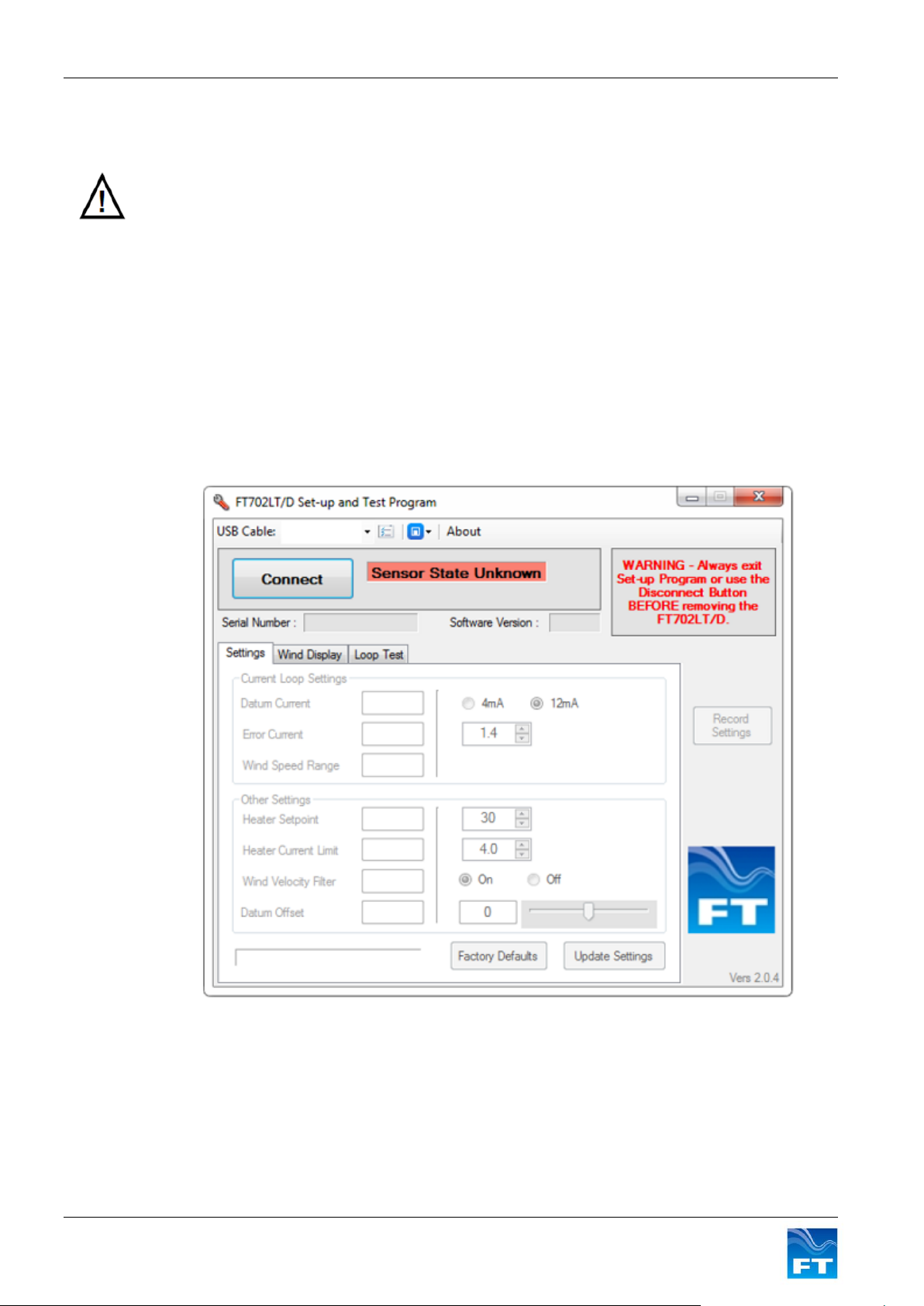
5.3 Change Settings
The settings can be changed on a sensor by using the Settings tab. This will show the current sensor settings
on the left and options that can be changed on the right. Select any new settings required on the right and then
click on the Update Settings button to apply them. The new sensor settings will then be displayed on the left.
Clicking on the Factory Defaults button will cause the settings to be reverted to factory default as per Figure 22
Please Note: Some functionality cannot be set for lower build versions of sensors. For example when an older
build version of the sensor is connected, some features are automatically deactivated and cannot be adjusted.
This is because the features are not available in the sensor.
Figure 24: FT702LT/D Set-Up and Test Program Settings
5.4 Sensor Report
The settings applied to a sensor can be reported using the Record Settings button. The following parameters
are then saved into a file every time the Record Settings button is clicked.
Serial Number
26 FT702LT/D Flat Front Wind Sensor Manual
Page 27
Section 5 Changing Settings
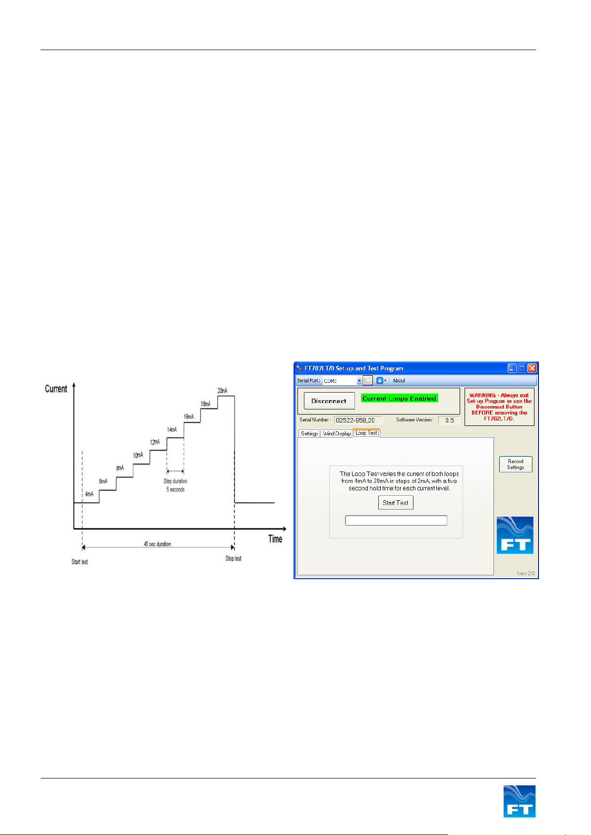
Figure 25: Current Loop Test Waveform
Figure 26: FT702LT/D Set-Up and Test Program
Loop Test
Software Version
Wind Velocity Filtering
Heater Set Point
Wind Direction Datum Rotation
Wind Direction Datum Current
Error Current
Wind Speed Range
Heater Current Limit
Date and Time of Report Generation (based on PC bios clock)
This report can be view or saved as a .CSV file and reviewed later in MS Excel or Notepad.
The location of the report file and its name can be changed by clicking Log File Settings button at the top of the
application.
5.5 Current Loop Test
Both current loop outputs can be automatically stepped through the 4-20mA range for test purposes. When the
loop test command is sent both loops are set to 4mA for a duration of 5 seconds. After 5s the loop current steps
by 2mA to 6mA. This process is repeated until the 20mA level is reached whereupon both loops return to the
wind measurement mode.
The current loop outputs during the test are shown in Figure 25.
To run the test select the Loop Test Tab, and click the Start Test button in the FT702LT/D Set-Up and Test
Program as shown in Figure 26.
27 FT702LT/D Flat Front Wind Sensor Manual
Page 28
Section 5 Changing Settings
Never unplug the wind sensor while the Set Up and Test Program is running as this may
leave the current loop outputs disabled. Always click on the Disconnect button and then
exit the Set-Up and Test Program before unplugging or powering down the FT702LT/D.
5.6 Reading the Wind Data
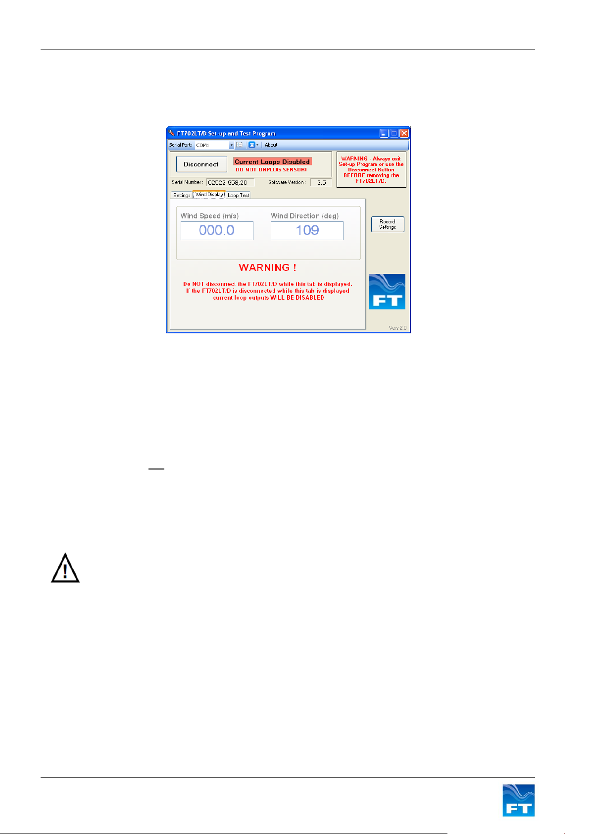
Select the Wind Display Tab. The wind speed (m/s) and wind direction (degrees) are displayed.
Figure 27: FT702LT/D Set-Up and Test Program Settings Wind Display
5.7 Wind Sensor Mode Warning
The state of the current loops is indicated at all times at the top of the program. When the FT702LT/D is in
communication with a computer it is in a digital mode and the current loops are disabled. If the sensor is
disconnected from the computer with the current loops disabled, the sensor will remain in this digital mode
and the current loops will not work. The FT702LT/D Set-Up and Test Program can be used to change
settings and check that the sensor is working but before unplugging the sensor the Disconnect button must
always be pressed first. The current loops state will then change to be re-enabled as indicated at the top of
the program. Once indicated, it is safe to exit the program and disconnect the sensor.
If a sensor has not been taken out of digital mode then open the Set-up and Test Program, re-connect the
sensor and click on the Connect button. The current loops should now be enabled as indicated at the top of
the program. Click the Disconnect button, close the Program and then disconnect the sensor. The sensor
will now be back in analogue mode.
End of Manual – Back to Contents
28 FT702LT/D Flat Front Wind Sensor Manual
 Loading...