

Page 1
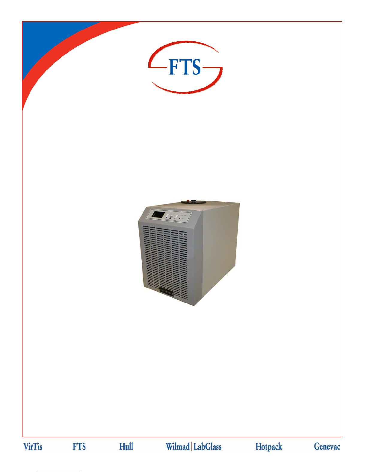
RSSeriesChillers
Operator’sManual
FTS
3538 Main Street
Stone Ridge, NY 12484 USA
(800) 824-0400 or 001 (845) 687-0071
www.SPIndustries.com
SP Service:
(877) 548-4666 or 001 (645) 687-5400
FAX: (845) 687-0024
E-Mail: [email protected]
Document #MNL-008-A, Rev. 009
Page 2

Notice
This Operation Manual contains confidential and proprietary information of SP Industries, Inc.
and may be used only by a recipient designated by and for purposes specified by SP
Industries, Inc.
Reproduction of, dissemination of, modifications to, or the creation of derivative works from
this manual, by any means and in any form or manner, is expressly prohibited, except with
the prior written permission of SP Industries, Inc. Permitted copies of this document must
retain all proprietary notices contained in the original.
The information in this document is subject to change without prior notice. Always confirm
with SP Industries, Inc. that you are using the most current version of this document. SP
Industries, Inc. is free to modify any of its products and services, in any manner and at any
time, notwithstanding the information contained in this document.
THE CONTENTS OF THIS DOCUMENT SHALL NOT CONSTITUTE ANY WARRANTY OF
ANY KIND, EITHER EXPRESSED OR IMPLIED, INCLUDING BUT NOT LIMITED TO THE
IMPLIED WARRANTIES OF MERCHANTABILITY AND/OR FITNESS FOR A PARTICULAR
PURPOSE OR GIVE RISE TO ANY LIABILITY OF SP INDUSTRIES, INC., ITS AFFILIATES
OR ITS SUPPLIERS.
The terms and conditions governing the use of this Operation Manual shall consist of those
set forth in written agreements with SP Industries, Inc.
All brand or product names mentioned may be trademarks or registered trademarks of their respective companies.
© 2007 SP Industries, Inc. All marks herein are used under license.
© SP Industries, Inc. MNL-008-A Rev. 009
ii
Page 3

Contents
Contents........................................................................................................................................ iii
Important Symbols........................................................................................................................ 4
Foreword ........................................................................................................................................ 5
Safety Precautions...................................................................................................................................... 5
Inspection ................................................................................................................................................... 6
Introduction.................................................................................................................................... 7
Model Number Identification .................................................................................................................... 7
Installation...................................................................................................................................... 8
Physical Location..................................................................................................................................... 8
Ambient Air Requirements ....................................................................................................................... 8
Selecting a Process Fluid ........................................................................................................................... 9
Process Fluid Properties.........................................................................................................................10
Electrical Requirements.............................................................................................................................11
High pressure Bypass Hook-Up (Accessory).............................................................................................12
Connect to the Process .............................................................................................................................13
Operation...................................................................................................................................... 14
User Menu .................................................................................................................................... 16
User Menu Layout .....................................................................................................................................17
Proportional Control Menu.........................................................................................................................18
Span Menu ................................................................................................................................................19
Miscellaneous Menu ..................................................................................................................................20
Communications Menu ..............................................................................................................................21
High Fluid Temperature .............................................................................................................................22
Low Fluid Temperature..............................................................................................................................23
PID Tuning.................................................................................................................................................24
IT and DT...................................................................................................................................................25
CCT ...........................................................................................................................................................25
CPB ...........................................................................................................................................................26
HPB, CPB, AND DB ..................................................................................................................................27
RS-232 Communications Programmer's Reference ................................................................ 28
Maintenance................................................................................................................................. 42
Troubleshooting .......................................................................................................................... 47
Service..........................................................................................................................................50
FTS Warranties and Service Agreements .................................................................................................50
Standard Warranty.....................................................................................................................................51
Service Options .........................................................................................................................................52
Extended Warranty: ................................................................................................................................52
Preventative Maintenance: .....................................................................................................................52
Service Contract: ....................................................................................................................................52
Return of FTS Equipment ..........................................................................................................................53
© SP Industries, Inc. MNL-008-A Rev. 009
iii
Page 4
ImportantSymbols
FTS designs and manufactures units to be safe and reliable systems. Safety features are
incorporated throughout and appropriate signs and symbols are provided. In this manual,
safety issues are addressed in context. Users are strongly encouraged to become familiar
with these symbols.
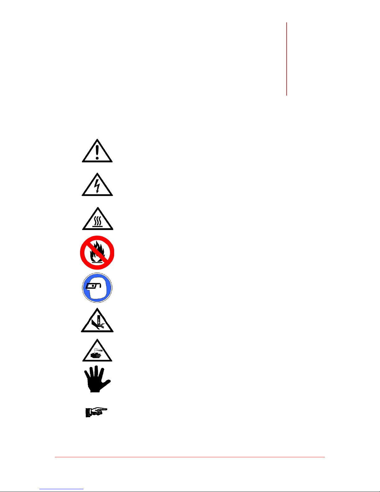
Warning! Refer to manual text. Injury or even death
may result if a recommendation marked with this symbol
is not heeded.
Electric Shock Danger! Use appropriate caution to avoid injury or death.
Burn Danger! Potentially hot surface. Use appropriate caution.
Do not store flammable materials in chamber.
Wear Safety Glasses.
Crush Hazard. Keep hands clear when operating door.
Corrosive Chemical. Wear suitable gloves, safety glasses, and protective
clothing.
Property Caution! To prevent damage to chamber equipment and/or load,
adhere to procedures marked by this symbol.
© SP Industries, Inc. MNL-008-A Rev. 009
Practical Operating Tip. These recommendations streamline unit operation and
prevent common operator errors.
4
Page 5
Foreword
Thank you for buying an SP Industries / FTS product. Our goal is 100 percent customer
satisfaction. If you are in any way dissatisfied with your order, please contact us immediately.
Safety Precautions
Your satisfaction and safety will be assured by a complete understanding of this equipment.
To assure your satisfaction and safety, as end user of this equipment, it is the operator’s
responsibility to understand its function and operational characteristics. Before operating this
equipment please read this instruction manual thoroughly. Ensure that all operators receive
appropriate training.
Awareness of the stated cautions and warnings, compliance with recommended operating
parameters, and performance of periodic maintenance requirements are important for safe
and satisfactory operation.
Your instruction and maintenance manual is valuable as it contains information to help you
better understand and operate the equipment you have purchased. It includes a wiring
diagram and contact numbers, which you may require at some future date. Keep it close at
hand and refer to it often. Additional manuals may be purchased from our Parts Department.
If any part of these instructions is not clearly understood, please feel free to contact Customer
Service for clarification.
If you require replacement parts, we must have the model and serial numbers plus all
electrical information from the nameplate.
CAUTION
As a routine safety precaution, always wear safety glasses when working
with this equipment.
The unit should be used for its intended application; alterations or modifications will void the
warranty. This product is not intended, nor can it be used, as a sterile or patient-connected
device, nor is it designed for use in Class I, II, or III locations as defined by the National
Electrical Code.
WARNING! FOLLOW THESE INSTRUCTIONS TO AVOID INJURY AND/OR DAMAGE TO EQUIPMENT.
Never use with toxic, corrosive, flammable or organic materials unless special precautions
are in place to prevent injury to personnel or damage to equipment.
Never operate unit without all covers in place.
Never clean with solvents. Use mild detergent and water only.
Never allow hands or body to be exposed to open vacuum ports.
Always verify that the electric service and other utilities match the unit’s requirements before
connecting to power.
© SP Industries, Inc. MNL-008-A Rev. 009
5
Page 6
Operator’s Manual: RS Series Chiller Foreword
Always wear safety glasses when using glass flasks.
Always practice team lifting when moving heavy equipment.
Always ensure that refrigeration air intake is clear and clean.
Always ensure that only an authorized technician services the refrigeration, heat transfer,
vacuum and electrical systems.
Always assume that internal parts may be very cold or very hot. Utilize personal protective
equipment to avoid burns.
Inspection
This merchandise was carefully packed and thoroughly inspected before leaving our factory.
Save all packing material if apparatus is received damaged.
Responsibility for its safe delivery is assumed by the carrier upon acceptance of the
shipment, therefore, claims for loss or damage sustained in transit must be made upon the
carrier by recipient as follows:
Visible loss or damage
Note any external evidence of loss or damage on the freight bill, or express receipt, and have
it signed by the carrier's agent. Failure to adequately describe any such external evidence of
loss or damage may result in carrier's refusing to honor your damage claim. The form
required to file such a claim will be supplied by the carrier.
Concealed loss or damage
Concealed loss or damage means loss or damage which does not become apparent until the
merchandise has been unpacked and inspected. Should either be discovered, make a written
request for inspection by the carrier's agent with 15 days of the delivery date; then file a claim
with the carrier since the damage is the carrier's responsibility. By following these instructions
carefully, we guarantee our full support of your claim to be compensated for loss from
concealed damage.
Do not -- for any reason -- return this unit without first obtaining authorization. Please
supply nameplate data, including model number and serial number, in any
correspondence to the manufacturer.
DO NOT STORE OR PROCESS FLAMMABLE MATERIALS
This unit is not designed (nor is it intended to be used) for the
purpose of processing or storage of materials that may
contain volatile flammable solvents or that may emit
flammable vapors during processing or storage.
© SP Industries, Inc. MNL-008-A Rev. 009
WARNING
6
Page 7
C
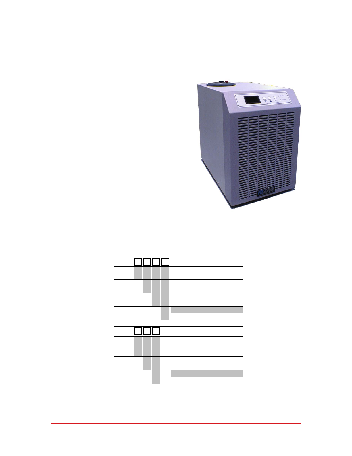
RS Series Chillers are portable, caster mounted
systems that provides temperature controlled
fluid over a wide range. All FTS chillers feature
innovative design, high-quality construction, and
high reliability components. This chiller will
reliably serve your cooling needs for years to
come.
Features include:
•Small Footprint
•Digital / RS-232 Control
•+/- 0.1°C stability
•Wide Temperature Range
•Mechanical Refrigeration (Air- Cooled)
hapter
1
Introduction
Model Number Identification
Copy the model number into the appropriate line below. Use the chart to check the
options that have been built into the unit. The model number is listed on the serial tag
on the rear of the unit.
RS33 Recirculator, 1/3HP
Voltage
Low Temp
Capability
Heater
Pump
Voltage
Low Temp
Capability
Pump
A 120V / 60Hz
D 220V / 50Hz
0 -10°C Low Temp
L -40°C Low Temp
0 No Heater
1 600W Heater (+75°C High Temp)
02GPM, 4psi
1 1.6GPM, up to 100°C
RS44 Recirculator, 1/3HP
B 230V / 60Hz
C 208V / 60Hz
D 220V / 50Hz
0 -10°C Low Temp
L -40°C Low Temp
02GPM, 4psi
2 1.6GPM, up to 100psi
© SP Industries, Inc. MNL-008-A Rev. 009
7
Page 8

Installation
Physical Location
The area where you place the unit should be smooth, level, and capable of safely supporting
the weight of the machine. Space should be provided so that air can properly circulate around
the unit. If obstacles are blocking the airflow, the compressor may overheat. This reduces
performance, and can lead to early compressor failure.
The environment should be well ventilated to prevent excessive build up of heat. Normal
room ventilation is usually adequate.
Ambient Air Requirements
This unit is designed for operation in a normal indoor environment. (Systems should not be
mounted outside or otherwise exposed to the elements). The environment should be free
from air containing large amounts of moisture, salt or sulfur. If your system utilizes an air-
cooled condenser, the fan in the system draws ambient air across the condenser (radiator) to
cool the refrigerant.
The ambient air temperature requirements are:
Chapter
2
55°F to 69°F (12°C to
21°C)
70°F to 75°F (21°C to
24°C)
75°F to 80°F (24°C to
27°C).
80°F to 85°F (27°C to
29.5°C)
Over 85°F (Over
29.5°C)
Acceptable
Ideal
Acceptable, but a reduction in the cooling capacity of the
unit is to be expected (about a 1% cooling capacity
reduction per degree above 72°F).
Expect reduced reliability. Warranty may be voided.
Not Acceptable. Warranty will be voided.
.
© SP Industries, Inc. MNL-008-A Rev. 009
8
Page 9

Operator’s Manual: RS Series Chiller Chapter 2: Installation
Fluid Temp Range(°C) Flammability Toxicity Dielectric
Glycol/Water
60/40
Glycol/Water/Methanol
60/30/10
Methanol -80/0 Medium Low Low
Ethanol -60/0 Medium Medium Low
Syltherm XLT -60/200 Low Very Low High
Silicone 1.0 -55/200 Low Very Low High
-30/60
-50/30
Low
Low
Low
Low
Low
Low
Selecting a Process Fluid
This recirculator is designed for operation with a host of industry standard fluids.
Which fluid you choose will depend partly on what temperature range you require.
Ethylene Glycol and water (60/40 mix) is an inexpensive and readily available fluid for
–25°C to +60°C. If you require a fluid outside this temperature range, FTS suggests
using HT-30 Silicone Oil for –60°C to +100°C.
There are other fluids available, but to avoid potential application problems and
to speed troubleshooting; it is suggested that one of the fluids mentioned above
be used. DO NOT USE AUTOMOTIVE ANTI-FREEZE (it contains clotting
agents) If for some reason one of the above fluids is not suitable, and you select
a different one, be sure that it has a viscosity of less than 20 centistokes over the
full temperature range of the unit. NOTE: All of the above mentioned fluids have
viscosity of less than 20 centistokes across their useable temperature ranges.
Since most systems have capability to achieve temperatures below 0°C, water should
not be used as a process fluid.
© SP Industries, Inc. MNL-008-A Rev. 009
9
Page 10

Operator’s Manual: RS Series Chiller Chapter 2: Installation
Process Fluid Properties
Expansion/Contraction
It is important to note that some fluids expand as much as 14% from +25°C to +125°C. Do not confuse contraction
of the fluid for fluid losses. Also, open the red vent screw on the reservoir lid when changing the setpoint (the
temperature the unit controls at).
Fluid Creep
Fluid Creep
Galden and similar fluids are very 'thin' and any non-sealed connection in the fluid loop will leak.
Dissolved Gases
At room temperature the fluid contains dissolved gas. As the fluid temperature is increased the amount of
dissolved gas decreases dramatically, causing excess gas to be released from the fluid. This release of gas
should not be mistaken for boiling of the fluid.
W ate r S o lub ility
Process fluids are water-soluble. After long periods of operation at low temperatures, water from the air will
condense on and mix with the fluid. this decreases the performance of the system. To remove the excess water,
warm the fluid to room temperature and pump the fluid through a molecular sieve or desiccant material.
Alternately, simply run the system at temperatures over 100°C, this will boil off any water present in the fluid. (Only
applies to the systems that are capable of temperatures over 100°C)
-
Low surface tension and high vapor pressure
This means that the fluid evaporates very easily and that any improperly sealed joints will leak. Close the red vent
screw on the reservoir lid to prevent excessive evaporation of the fluid, but remember to open the vent screw when
changing setpoints (the fluid expands and contracts with temperature changes).
© SP Industries, Inc. MNL-008-A Rev. 009
10
Page 11
Operator’s Manual: RS Series Chiller Chapter 2: Installation
Electrical Requirements
Only qualified personnel should perform the installation of this
unit.
The voltage and frequency requirements are specified on the serial tag on the rear of the
unit. Standard variances in frequency (+/-3Hz) and voltage (-5%, +10%) are allowed.
•Verify that the facilities voltage matches the requirement for the machine, which is
printed on the serial tag on the rear of the machine.
•The electric service wiring must be of a large enough wire gauge that the voltage is
maintained to the receptacle even when a full load is applied to the receptacle.
Additionally, the receptacle voltage should be measured while that receptacle is
under load.
•This unit has a NEMA 5-15P or 6-15P line cord, install an appropriate (NEMA 5-
15R or 6-15R) receptacle where the unit is to be run. (some 50 Hz machines are
shipped with no plug)
•Ensure the proper amperage circuit breaker is installed in the line and located near
the equipment.
•Plug in the line cord. (Avoid the use of long extension cords, these cause a
significant power drop between the wall receptacle and the machine.)
• When the unit is plugged in the amber POWER light on the front panel should
illuminate
NOTE: For Lock Out / Tag Out plug the appropriate device into
the line cord.
© SP Industries, Inc. MNL-008-A Rev. 009
11
Page 12
Operator’s Manual: RS Series Chiller Chapter 2: Installation
High pressure Bypass Hook-Up (Accessory)
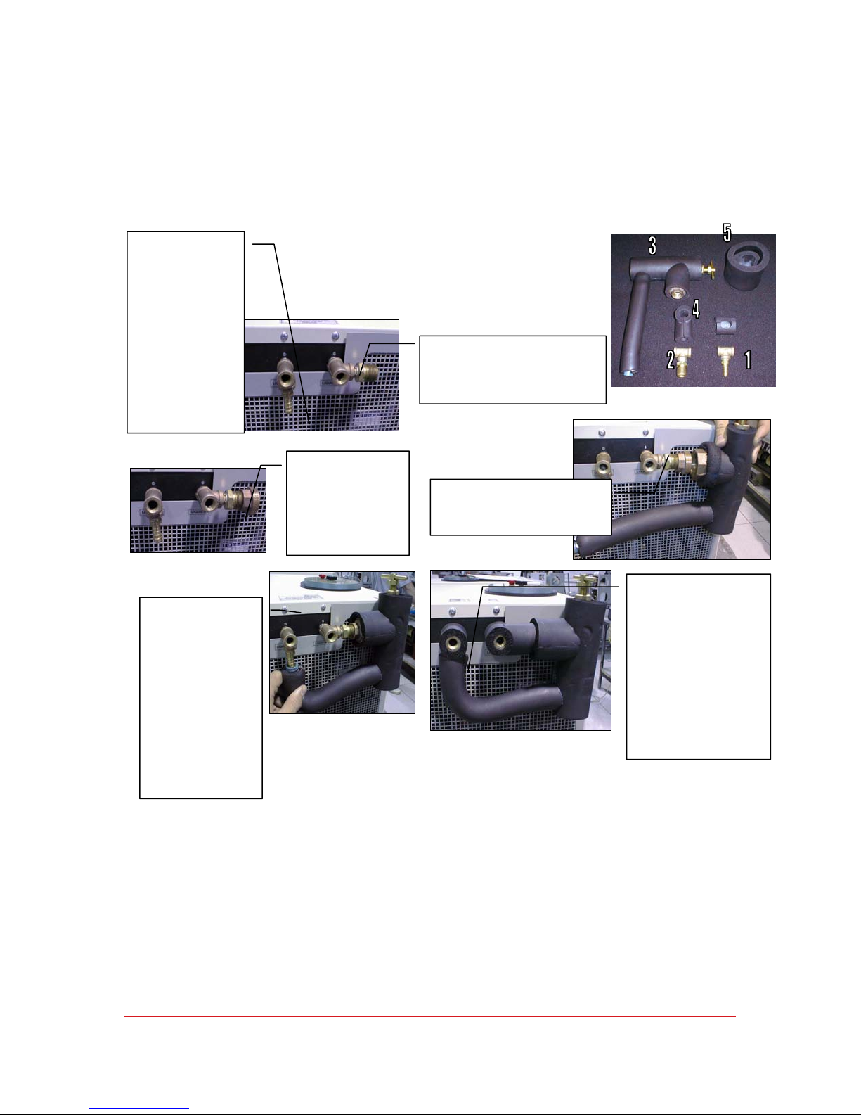
The high pressure bypass allows the user to control the pressure of the process fluid going to
the application. This is particular can be useful if an application is sensitive to pressure such as
a glass jacketed reaction vessel.
1) Thread Part 1
onto the
process fluid
output and
tighten. The
barb should
face down.
(remember to
use pipe thread
sealant on all
metal to metal
connections)
3) Take Part 3,
remove the
coupling and
thread it onto
Part 2 as shown,
tighten.
2) Thread Part 2 onto the process
fluid input and tighten. The opening
should point toward left-hand side of
the machine (operators left when
looking at the control panel).
4) Pull the insulation on
Part 3 back as shown.
Tighten the coupling.
5) Slide the hose
from Part 3 all
the way onto the
hose barb on
Part 1. Position
the hose clamp
and tighten so
that the hose is
firmly gripped
between the
hose barb and
the hose clamp.
Add Part 4, the
insulation covers, to
parts 1 and 2.
Connect process
fluid lines to Parts 1
and 2 as per the
following
instructions.
Part 5 is the
insulation cover for
the T-Handle.
© SP Industries, Inc. MNL-008-A Rev. 009
12
Page 13
Operator’s Manual: RS Series Chiller Chapter 2: Installation
Connect to the Process
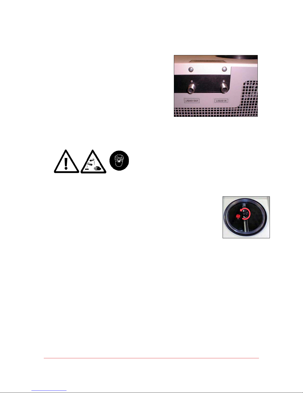
FTS provides input and output connections for the
process fluid. To tie these lines into your process,
you will need:
•1/4” Fittings for 1/4” male pipe thread on the
Fluid I/O ports (3/8” Fittings for 3/8” male pipe
thread on the Fluid I/O)
•3/8” ID tubing is recommended (1/2”ID
tubing for RS75)
•Pipe Insulation (Closed cell pipe insulation
will work for most applications. It can be
purchased from any local refrigeration or
plumbing supply house.)
•Glue seams of pipe insulation
•Teflon tape pipe sealant to seal all fittings
Always use caution when handling fluids, filling or draining the
system reservoir, or working in or around the chiller. Always
wear protective eyewear when operating the chiller.
Add Fluid
Once the fluid loop that runs to your application and back is in
place and sealed, fluid can be added to the reservoir. The
system can then be primed.
•Remove reservoir lid
•Fill reservoir to 1” (2.5cm) from the top and replace the lid.
•Press the I/O button (the pump will begin circulating fluid, if
more fluid is need to fully prime the process, immediately press
the I/O button to stop the pump. Add more fluid, tighten lid and
press the I/O button. Repeat this process of cycling the pump
and adding fluid until the system is fully primed.
Your unit is now fully installed and ready to operate.
© SP Industries, Inc. MNL-008-A Rev. 009
13
Page 14
System Preparation
•Plug the unit in if it is not already plugged in.
•System is now in Idle.
•Display will be blank and the amber Power light will
be illuminated
Start Up
•Press I/O button
•Display flashes SP (setpoint) then the current setpoint
temperature. (The setpoint is the temperature that the unit will
maintain the fluid temperature at.)
•Adjust the Setpoint using the ▲▼ keys.
•Value for setpoint will be accepted after 4 seconds of inactivity.
Chapter
3
Operation
Control
•When the system is running touch the ▲ button to bring up the
setpoint.
•Adjust the setpoint using the ▲▼ keys.
•The setpoint is automatically accepted after 4 seconds.
Shut Down
•Press the I/O button to put the unit back in Idle.
•The refrigeration will shut down and the display will blank.
•The amber Power light will remain lit.
© SP Industries, Inc. MNL-008-A Rev. 009
14
Page 15
Operator’s Manual: RS Series Chiller Chapter 3: Operation
NOTE: When changing setpoint, loosen the red vent screw
on the reservoir lid to accommodate for the expansion /
contraction of the process fluid. Once the chiller stabilizes
at a setpoint, tighten the red vent screw. This will help
prevent excess evaporation of the fluid, as well as
preventing atmospheric moisture from condensing on the
fluid.
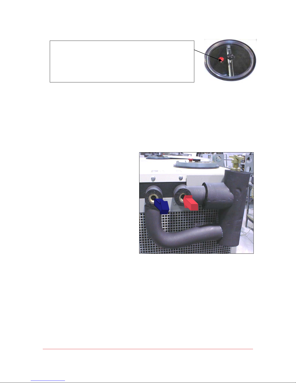
High Pressure Bypass Adjustment
If using a High Pressure
Bypass, take off the insulated
valve cover. Use the brass THandle to adjust the operating
pressure of the system to the
desired levels.
© SP Industries, Inc. MNL-008-A Rev. 009
15
Page 16
Chapter
4
UserMenu
This unit is equipped with an EDC digital control package. Varying the
parameters in the EDC Controller’s User Menu allow the operation of the unit to
be fine tuned to meet the needs of a specific application. A variety of parameters
such as Ramp Rate, Auto-Power Recovery, High and Low Temperature Alarms,
Parameter Lock, Setpoint Limits, readout options, Proportional Control
parameters, and several Communications options can all be adjusted from the
User Menus.
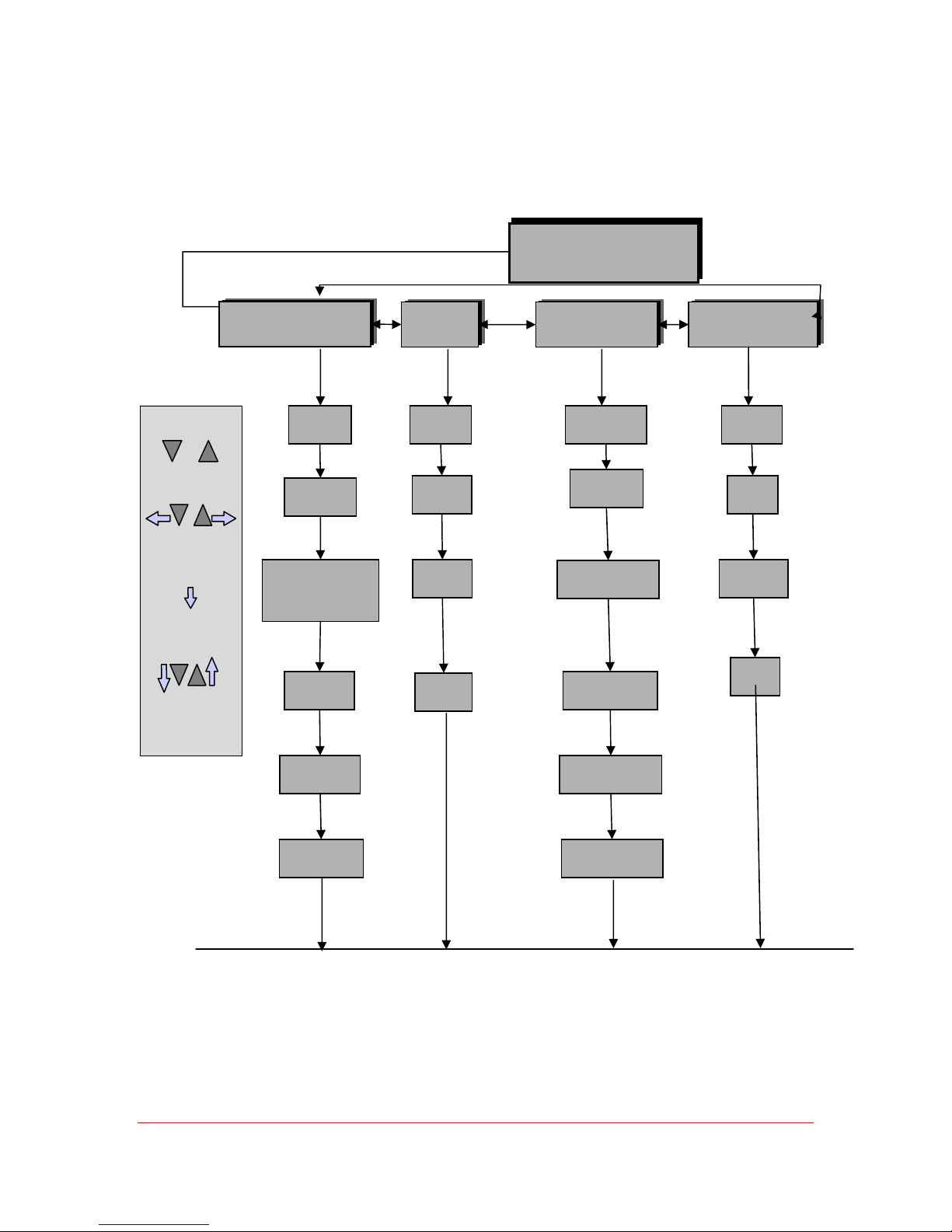
The layout of the menus and parameters contained in those menus is shown on
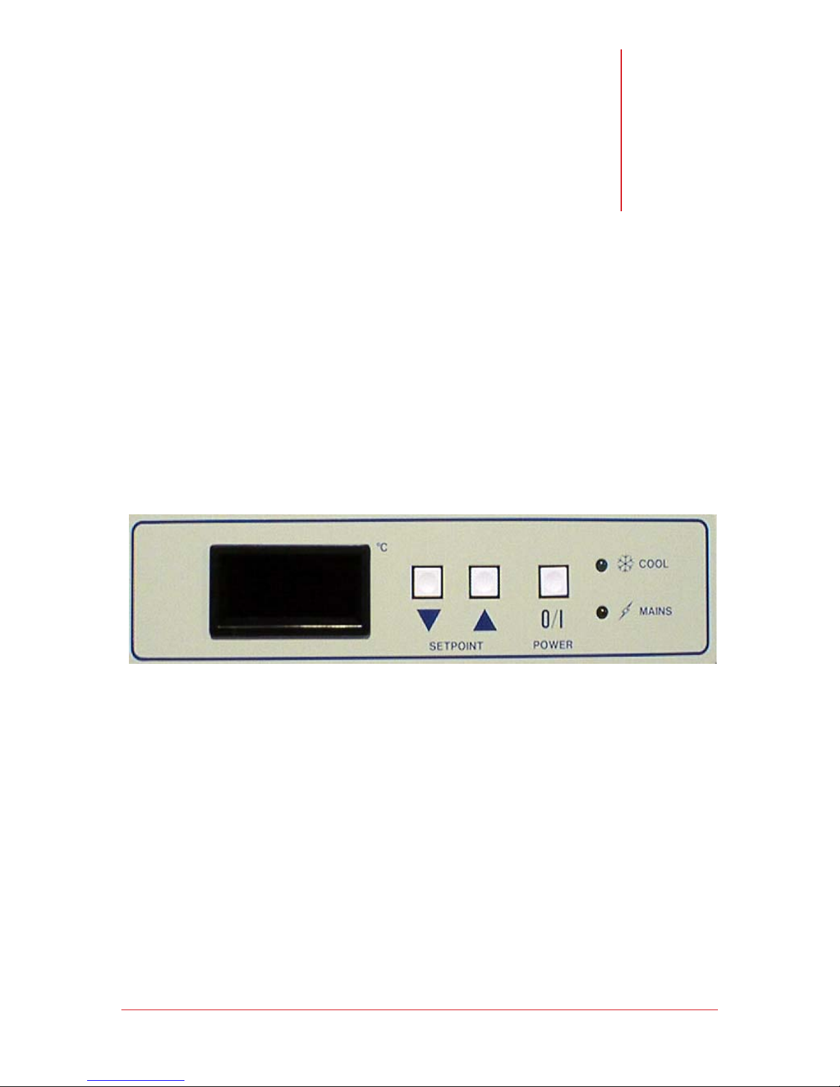
the following pages. They are navigated using the three buttons on the front
panel of the EDC Controller. The legends on the following pages show how to
use these buttons to move around the menus and manipulate the values of the
various parameters.
© SP Industries, Inc. MNL-008-A Rev. 009
16
Page 17
Operator’s Manual: RS Series Chiller Chapter 4: User Menu
User Menu Layout
Operating Mode
(Unit is running or in IDLE)
Press & Hold
Or
To view Menus
Choose Menu
I/
Move down to
next parameter
Adjust
Parameter
Value
Pid
Proportional Control Menu
rr
Ramp Rate
CPb
Cooling Band
HPb
(RS33 only-heat option)
Integral Time
It
Integral Time
dt
Derivative Time
SPAn
Span Menu
HA
High Alarm
LA
Low Alarm
SH
Span High
SL
Span Low
Etc
Miscellaneous Menu
PLOC
Parameter Lock
dP
Decimal Point
PF
Power Fail Recovery
dEg
Temperature Scale
rdy
“Ready” Temp. Band
232
Communication Menu
baud
Baud Rate
Sbit
Stop Bit
dAtA
Word Length
PAr
Parity
Cct
Cool Cycle Time
Once a menu has been completed you are returned to the Operating Mode
© SP Industries, Inc. MNL-008-A Rev. 009
rdyt
“Ready” Time Const.
17
Page 18
Operator’s Manual: RS Series Chiller Chapter 4: User Menu
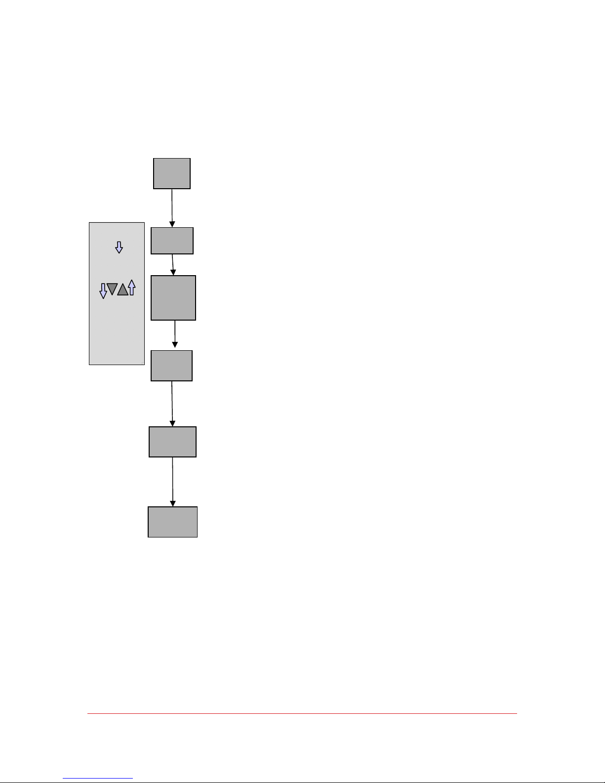
Proportional Control Menu
I/O
Move to next
parameter
Adjust
Parameter
Value
rr
Ramp Rate
CPb
Cooling Band
HPb
(RS33 onlyheat option)
Integral Time
It
Integral Time
dt
Derivative Tim e
Programmed transition rate from old setpoint to new setpoint, in
degrees per minute. Ramp Rate is more of a slew limiter, because
the available ramp rate is obviously limited by the thermal load and
the pulldown capacities of the refrigeration system.
Width of the temperature span across which cooling is
proportionately applied to the process, in degrees. Note: this is
band centered on the setpoint, so a CPb of 5 degrees defines a
window that’s +/- 2.5 degrees from the setpoint.
Width of the temperature span across which heat is
proportionately applied to the process, in degrees. In a heat-only
mode this would equate to +/- 2 degrees from setpoint. In this
system (heat/cool operation) the band is offset below setpoint
and then further shifted up or down by the Deadband/overlap
parameter.
Integral (Automatic Reset) time, in seconds. Time constant for
adjustment of proportioning action that serves to correct deviations
from setpoint.
Derivative (Rate of Change adjustment) time, in seconds. Time
constant for adjustment of proportioning action in order to reduce
the slew rate of the process as it approaches the setpoint.
Derivative time is automatically limited to 1/4 of the Integral Time
(It).
Cct
Cool Cycle Time
© SP Industries, Inc. MNL-008-A Rev. 009
Period of operation of the cool/bypass refrigeration valves, in
seconds. In order to reduce wear on the solenoids and valves, the
period (total time on and off) may never be less than two seconds.
Additionally, the duration of either On or Off is never less than 0.25
seconds.
18
Page 19
Operator’s Manual: RS Series Chiller Chapter 4: User Menu
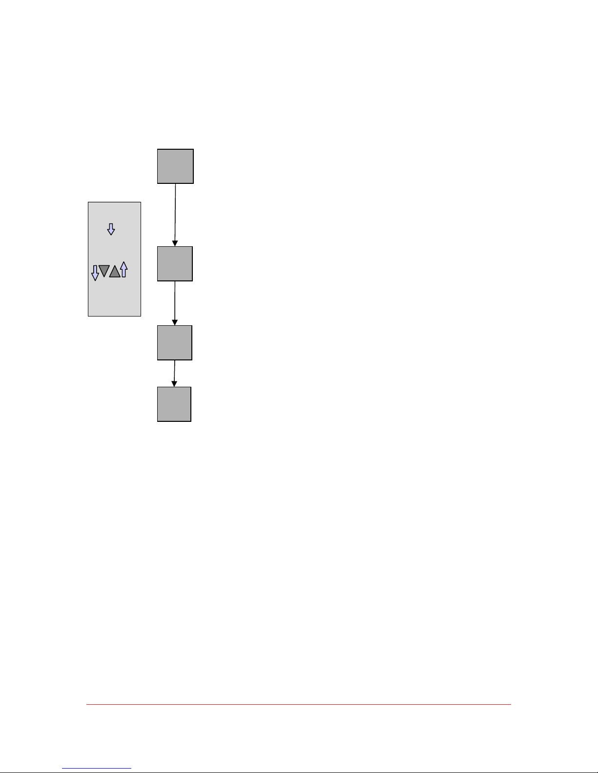
Span Menu
An alarm can be set to alert the user that the process
temperature is too high. Should the HA be triggered, the system
will go to FULL COOL and the display will flash HA. The
temperature alarms are monitored even if the system is in IDLE,
in case the user turns off the system without removing the load;
in such an instance, however, the unit is incapable of supplying
full cool, and it is the responsibility of the user to correct the
anomaly.
I/O
HA
High Alarm
Next
Parameter
Adjust
Parameter
Value
LA
Low Alarm
SH
Span High
SL
Span Low
Same as HA, except the system will stop all refrigeration and
display LA
Both HA and LA require user reset; clear the messages by pressing
the ∇ key. They will not disappear even if the process returns to the
correct level.
SH defines the maximum allowable setpoint. Adjust
the values of Span High and Span Low to define the
range of setpoints acceptable for your particular
application.
SL defines the minimum setpoint in this range.
© SP Industries, Inc. MNL-008-A Rev. 009
19
Page 20
Operator’s Manual: RS Series Chiller Chapter 4: User Menu
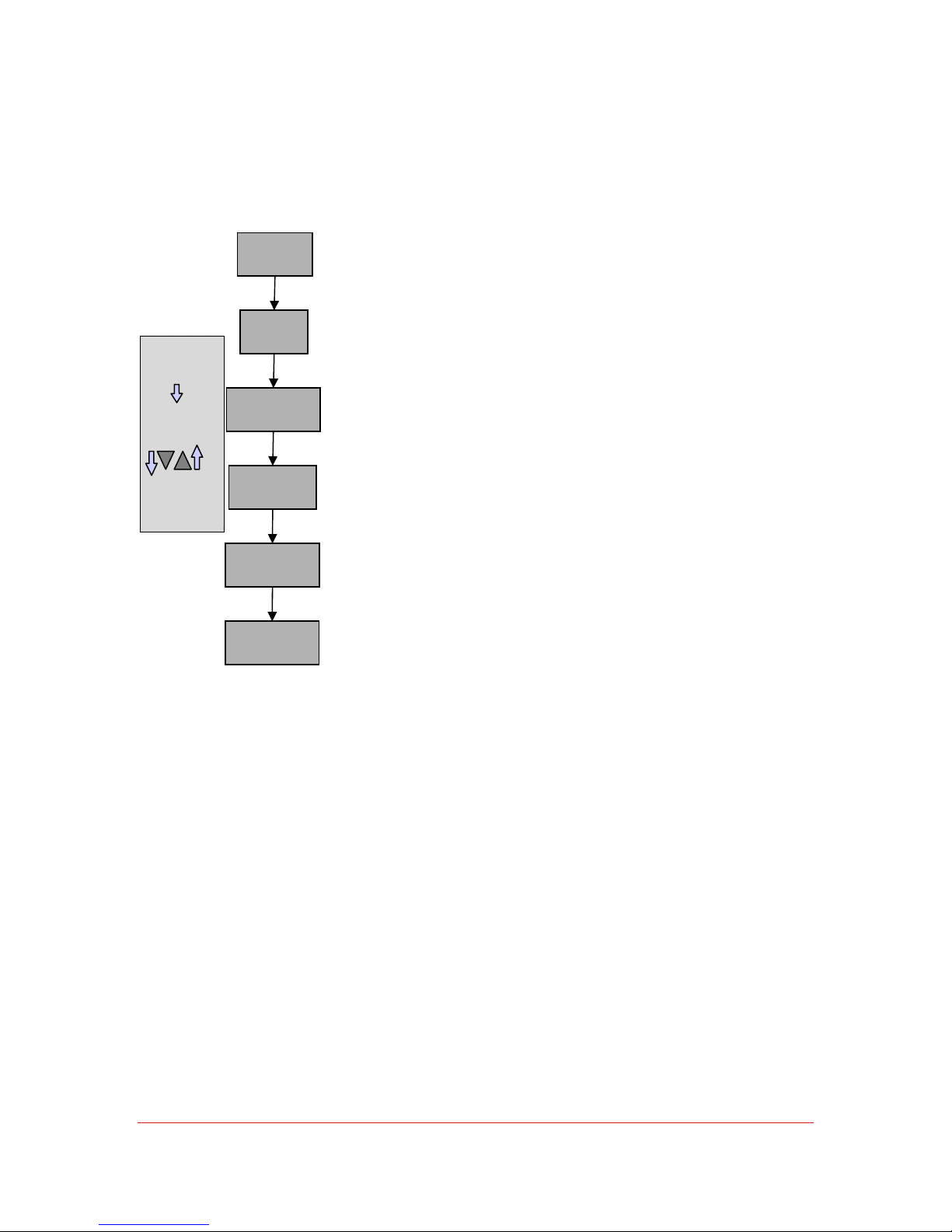
Miscellaneous Menu
I/O
Next
Parameter
Adjust
Parameter
Value
PLOC
Parameter Lock
dP
Decimal Point
PF
Power Fail Recovery
dEg
Temperature Scale
rdy
“Ready” Temp. Band
rdyt
“Ready” Time Const.
If set to 1, operating parameters may not be changed unless system
is off (not running). Note that if this is set while the unit is running, it
may not be reset unless the system is first turned off.
If set to 1, decimals will be displayed. If set to 0, readout will be in
integer format.
NOTE: Residual decimals will be carried internally. Therefore,
before using integer format, the SP should be corrected to xx.0 prior
to suppressing the decimal point.
The power failure recovery setting determines what the controller
will do following a power failure. If set to 1 the controller will
automatically restart the system if it was running when power was
lost. The display will show “PF” to indicate that there was a power
failure. (Clear PF message by pressing the ∇ key) If set to 0 the
Auto-Recovery function is shut OFF.
For Celsius set: 0
For Fahrenheit set:
1 For
Kelvin set: 2
The temperature band about SP, in degrees, by which the system
may be defined as "ready". The "ready" value (0/1) is normally
available via a query to the chiller via the RS-232. Note that this is a
"band". The default value of 5.0 thus equates to +/- 2.5 degrees
from SP. The Ready Temperature operates in conjunction with the
Ready Time described by the next parameter.
A time constant, in seconds, which the software uses to
determine the "ready" condition. The process temperature is
continuously integrated across a period of time defined by this
constant to ensure that stability has been achieved.
© SP Industries, Inc. MNL-008-A Rev. 009
20
Page 21
Operator’s Manual: RS Series Chiller Chapter 4: User Menu
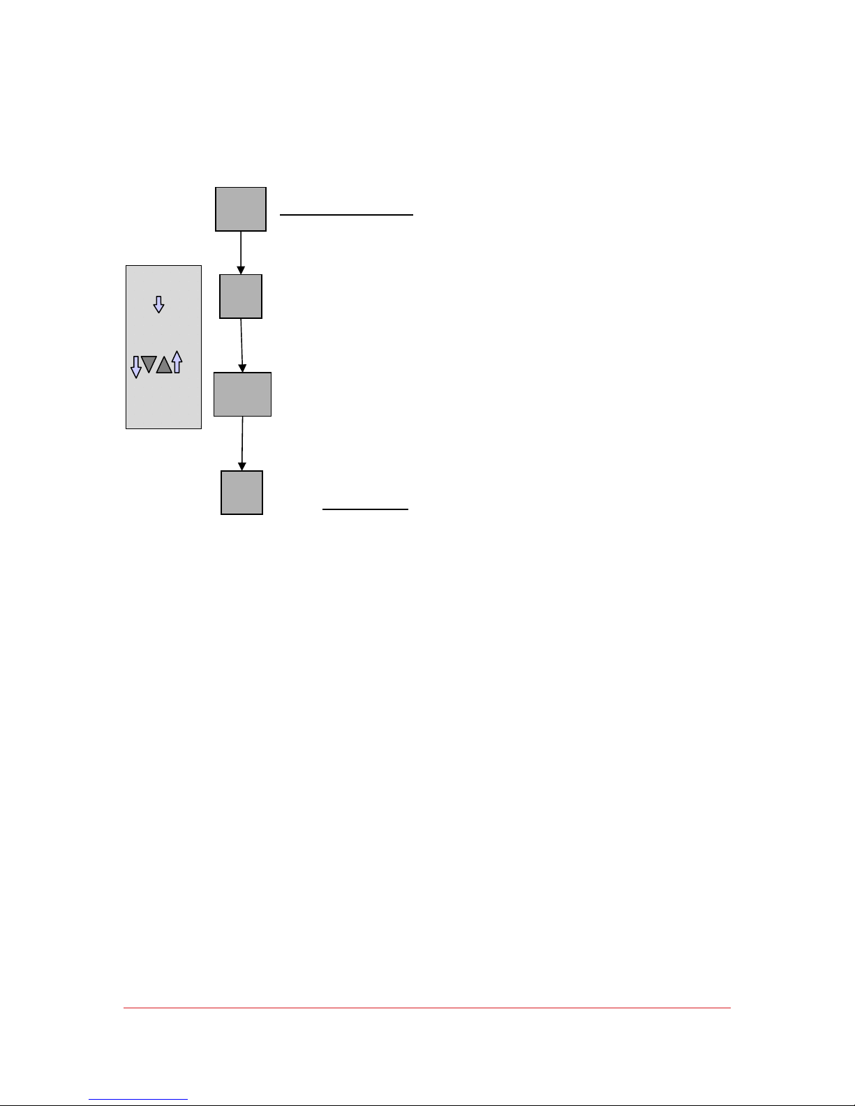
Communications Menu
Baud Rate for the RS-232 control communications port may be set
according to the table.
I/O
Next
Parameter
baud
Baud Rate
Sbit
Stop Bit
Display Baud
0 300
1 1200
2 2400
3 9600
The number of stop bits (1, 1.5, 2) may be selected
Adjust
Parameter
Value
dAtA
Word Length
PAr
Parity
Data word length may be set to 7 bit or 8 bit
Parity detection may be selected per the following:
Display Parity
0 none
1 odd
2 even
Note: Data word 8 bit length forces “no parity.”
© SP Industries, Inc. MNL-008-A Rev. 009
21
Page 22

Operator’s Manual: RS Series Chiller Chapter 4: User Menu
High Fluid Temperature
How Reported:
Description:
How Detected:
Appropriate
Response:
The display will flash HA, and the system will go to FULL COOL.
Indicates that the temperature of the process fluid going to the
equipment is higher than the level set (HA) to trigger the high fluid
temperature alarm. This is a user feature that can be adjusted to
the desired temperature by altering the value for HA in the SPAN
menu. If the thermal load is greater than the chiller’s heat removal
capacity, the unit will not be able to hold the setpoint temperature.
This situation is potentially damaging to equipment, so set the HA
just above the setpoint temperature so that you are alerted of
temperature runaways before they damage equipment.
A thermocouple monitors the temperature of the fluid leaving the
chiller.
Check the setting of the high temperature alarm (HA) by pressing
and holding the Δ button while the system is in idle, to get into
program mode. Then using the Δ and ∇ keys find the SPAn menu,
press I/0 button until HA is displayed, note the temperature for HA.
Press I/0 button until you exit the menu, Start system to show the
current setpoint. Then either decrease the temperature setpoint to
ensure it is set below the high temperature alarm setting (HA), or
adjust the HA value so that it is above the desired setpoint. If the
HA still goes off, check that the thermal load being applied by your
process is within the heat removal capacity of this unit. Contact the
FTS Service Division if the condition persists.
© SP Industries, Inc. MNL-008-A Rev. 009
22
Page 23

Operator’s Manual: RS Series Chiller Chapter 4: User Menu
Low Fluid Temperature
How Reported:
Description:
How Detected:
Appropriate
Response:
The display will flash LA, and the system will go to full bypass.
Indicates that the temperature of the process fluid going to the
equipment is lower than the level set for the low fluid temperature
alarm (LA). The user can set the temperature that this alarm will be
triggered by altering the value for LA in the SPAN menu.
A thermocouple monitors the temperature of the fluid leaving the
chiller.
Check the setting of the low temperature alarm (LA) by pressing
and holding the Δ button while the system is in idle, to get into
program mode. Then using the Δ and ∇ keys find the SPAn menu,
press I/0 button until LA is displayed, note the temperature for LA.
Press I/0 button until you exit the menu. Start system to show the
current setpoint.
Then either increase the temperature setpoint to ensure it is set
above the low temperature alarm setting (LA), or adjust the LA
value so that it is lower than the desired setpoint. Contact the FTS
Service Division if the condition persists.
© SP Industries, Inc. MNL-008-A Rev. 009
23
Page 24
Operator’s Manual: RS Series Chiller Chapter 4: User Menu
PID Tuning
Since each installation has different conditions of operation (ambient temperature,
water temperature, different fluid loop length, etc), the factory PID settings do not
always provide optimum control at the required temperature setpoint.
Press & Hold
Or
To view Menus
Choose PID
Menu
I/O
Accept
displayed value
and move to
next parameter
Adjust
Parameter
Value
Use the instructions outlined below to view and adjust the PID
settings.
To get to the menus press and hold the Up Δ or Down ∇ button.
Once in Program Mode use the Up Δ and Down ∇ buttons to move
between menu headings. When PId is displayed, press I / O.
Once inside a menu, use the Up Δ and Down ∇ buttons to adjust the
value of parameters. The I / O button accepts the value displayed
and steps down to the next parameter in the menu.
After the last parameter has been stepped through, you are returned
to the Operational Mode.
The following pages contain the basics of how to go from the values
at right and tune the unit for your specific application. In most cases
it is sufficient to just calculate a new Integral Time (It) and enter that
into the controller.
© SP Industries, Inc. MNL-008-A Rev. 009
24
Page 25
Operator’s Manual: RS Series Chiller Chapter 4: User Menu
IT and DT
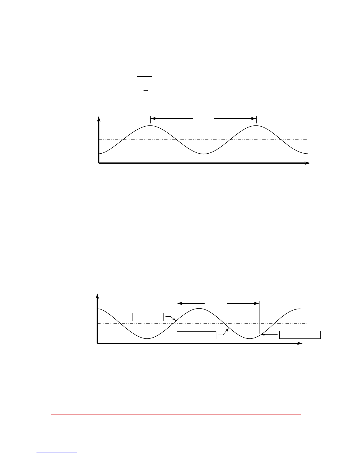
Measure the period of the temperature oscillations, peak temperature to peak temperature.
time(t)
It Time Integral
==
4
It
≤=
dt Time Derivative
4
NOTE: This represents the
maximum value for derivative
time. It can be lowered.
Temp
Program the results into the controller using the instructions outlined in PID Tuning.
Time (t)
Time
CCT
To determine the Cool Cycle Time (CCt), run the unit at the temperature
that you wish the unit to control best at. The temperature will probably
oscillate as the controller attempts to maintain temperature at the
setpoint.
Watch the Cool Light
Start a stopwatch when the Cool light comes on, wait for the light to go
off, and stop the stopwatch when the temperature begins to rise again.
Using the instructions on PID Tuning, set the the value of CCt = time on
the stopwatch (in seconds).
Setpoint
Example:
Temp
© SP Industries, Inc. MNL-008-A Rev. 009
Cool LED ON
Cool LED OFF
Time
25
Time (t)
Setpoint
Rise in
Page 26
Operator’s Manual: RS Series Chiller Chapter 4: User Menu
=+=
CPB
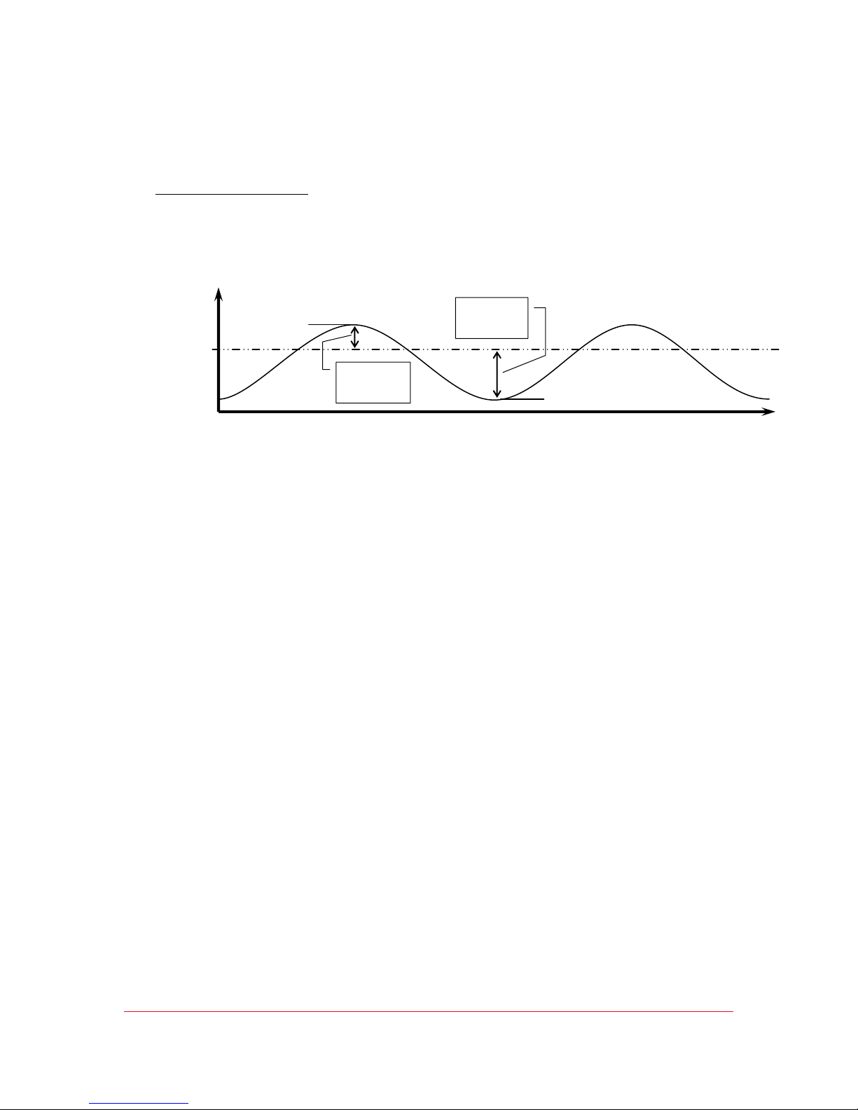
Note the amount the temperature swings above and below the setpoint. The temperature
swing is used to figure the proportioning band.
Cool Proportioning Band
CPb = Temperature swing below setpoint + 10% of that temperature swing
Example:
(CPb)
Temp
20°C
21°C
1°C above
setpoint
°+°=
Program the results into the controller using the instructions outlined in PID Tuning.
NOTE: New values for CPb are only processed with a new setpoint. Therefore after
entering a new value for CPb, it is necessary to get out of the Program Mode (successive I
/O’s) and change the setpoint. Once in the Operation Mode, change the setpoint (press the
Up Δ key twice and then I / O), then you can change it back (press the Down ∇ key twice,
and press ENTER). The new value for CPb will now be used.
2°C below
setpoint
Time
1.1 0.1 1 C1 of 10% C1 CPb
18°C
Setpoint
© SP Industries, Inc. MNL-008-A Rev. 009
26
Page 27
Operator’s Manual: RS Series Chiller Chapter 4: User Menu
=+=
HPB, CPB, AND DB
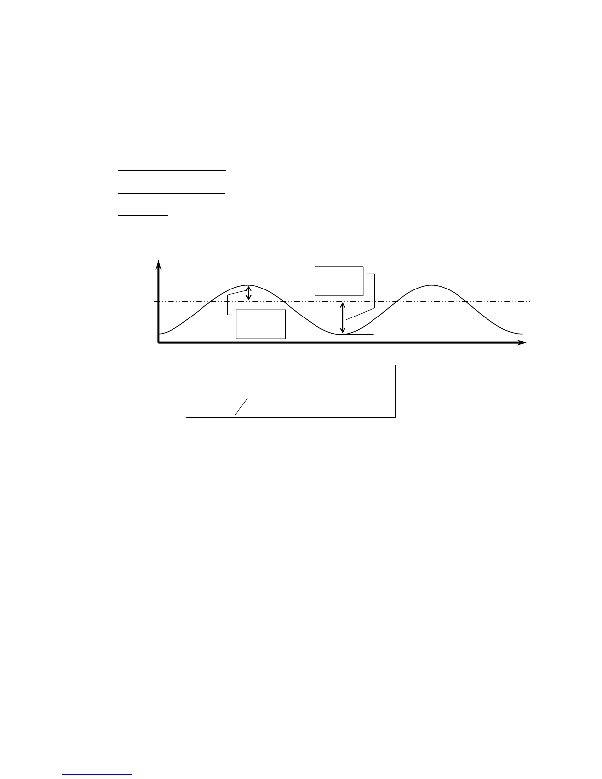
Note the amount the temperature swings above and below the setpoint. These
temperature swings are used to figure the proportioning bands and the dead band.
Heat Proportioning Band
HPb = Temperature swing above setpoint + 10% of that temperature swing
Cool Proportioning Band
CPb = Temperature swing below setpoint + 10% of that temperature swing
Dead Band
db = HPb or CPb (whichever is lower) divided by 2 and then rounded down.
Take the result and make it negative.
(db)
(RS33 – Heat option only)
(HPb)
(CPb)
Example:
Temp
20°C
21°C
1°C above
setpoint
2°C below
setpoint
18°C
Time
°+°=
C1.1
°
()
db
−=
2
1.1 0.1 1 C1 of 10% C1 HPb
2.2 0.2 2 C2 of 10% C2 CPb
=+=°+°=
0.5 down rounded C55.0
−=°−=
Setpoint
NOTE: New values for HPb, CPb, and db are only processed with a new setpoint.
Therefore after entering new values for HPb, CPb, and db it is necessary to get out of the
Program Mode (press ESC) and change the setpoint. Once in the Operation Mode,
change the setpoint (press the Up Δ key twice and then ENTER), then you can change it
back (press the Down ∇ key twice, and press ENTER). The new values will now be used.
© SP Industries, Inc. MNL-008-A Rev. 009
27
Page 28

Chapter
5
RS‐232Communications
ProgrammerʹsReference
OVERVIEW
The MPC and EDC controllers are used in a variety of cooling products manufactured by FTS.
The commands used by a specific system will vary per the descriptions at the end of this
reference, but the operational aspects, hardware and software, of the interface are consistent
across the product line. This document details the communications interface between the
microcontroller and the [independent] intelligent host processor.
At the end of this chapter is a sample program which will execute on an IBM-compatible PC
within either GWBASIC or QBASIC. It is suggested, should initial attempts to communicate be
unsuccessful, that this program be tried. It is as unencumbered as a program may be and will aid
in locating the source of difficulty: if this program runs successfully, then the difficulty must be due
to one of the “extras” or “features” of the unsuccessful driver.
HARDWARE
The hardware of the RS-232 interface meets or exceeds the specifications of EIA standard
RS-232-E-1991, with regard to electrical characteristics (impedance, open-circuit characteristics,
voltages, etc.).
The physical interface connector is a 9-position female D-subminiature connector, with pin-out as
specified by the IBM Corporation for the "PC-AT" [COM1] communication port.
The connections used within the interface will be limited to:
GND Signal Ground
TXD Transmit Data
RXD Receive Data
All other signals of the RS-232 standard are immaterial to this application, or terminated, as
appropriate.
Communications
Communication operates at a user-definable BAUD rate selectable from 300, 1200, 2400, 9600.
Parity may be odd, even, or none. The interface uses one Start bit and either one, one-and-a-half,
or two Stop bits (user-selectable).
Data word length is selectable at 7-bit data with designated parity, or 8-bit data without parity. All
data in both directions is transmitted in ASCII.
Selections of BAUD rate, parity, and stop bits are made to the microcontroller via the control
panel of the target (application) system.
© SP Industries, Inc. MNL-008-A Rev. 009
28
Page 29

Operator’s Manual: RS Series Chiller Chapter 5: RS232 Communications
COMMUNICATION DATA
All programmable, selectable, or switchable functions of the target system are accessible via the
RS-232, with the exception of the RS-232 configuration itself, which may not be programmed
from the host.
All data, programmed values, status, and system errors are accessible by the host, i.e., an
appropriate query by the host will result in a data stream returned from the system as defined
below.
DATA FORMAT
All data is transmitted in ASCII. All data values are transmitted via decimal character strings.
Upper and lower case alphabetic characters will be accepted interchangeably. Data descriptions
are identified by direction from the perspective of the system controller:
Received (from the host system to the MPC/EDC) and Transmitted (from the MPC/EDC to the
host) data.
RECEIVED DATA
Data may be transmitted at any time by the host. Status queries will be answered whether or not
the unit is in local or remote. Any change in system status (except "Goto Remote") requested via
the RS-232, however, will require that the unit be in the "remote" state; otherwise an error will be
reported to the host.
Data uses a "line" format, consisting of the following:
CMD <opt CMD> <opt CMD> <...> CR <opt LF>
where:
CMD is any valid transmitted data string
CR is an ASCII "Carriage Return"
LF is an ASCII "Line Feed"
Data commands may be grouped within a "line" command, or transmitted singly.
A data string must be terminated by a "Carriage Return" (ASCII 013 decimal / 0D hex). "Line
Feed" (ASCII 010 decimal / 0A hex) may be optionally inserted by the host, but will be ignored. A
"line" may not exceed 128 characters.
A listing and description of the available CMD statements appears in a later section.
Data commands which are grouped on a line must be separated by a single "Space" (ASCII 032
decimal / 20 hex).
The Delete/Rubout character (ASCII 127 decimal / 7F hex) will NOT be recognized.
Unrecognized characters will result in an error acknowledge.
ANY error in transmission/reception of a "line" will assume corruption of the ENTIRE line,
and ALL commands in that line will be ignored. This includes not only transmission (e.g., parity)
errors, but values out-of-bounds, undefined commands, etc. This ensures that state changes are
not presented to the system (e.g., new Setpoint SP) without all corresponding desired changes
(such as corresponding PID values).
© SP Industries, Inc. MNL-008-A Rev. 009
29
Page 30

Operator’s Manual: RS Series Chiller Chapter 5: RS232 Communications
All data received by the target system will be presented by the host system as a
character string of one of the following formats:
1) Absolute Command
Basic system functions/commands will consist of a fixed character string.
Examples:
"START" -- Wake up system
"STOP" -- Shut down system
"POLL" -- Force a response from the system
2) Parametric Command
A parametric command describes a function/command for which a value must be
specified. The command characters must be followed by an "equals sign" ("=") (ASCII 061
decimal / 3D hex), and a data string of decimal value.
The value may optionally contain a decimal point (except where required to define
decimal fractions). Negative values require a "minus sign" ("-", ASCII 045 decimal / 2D hex)
between the "equals sign" and the value. A plus sign ("+") may be used, but is not required.
Each programmable value within the system is assigned a set of limits by the system.
Certain of these limits may be further modified by other program commands. Values which
exceed the boundaries of either of these limits will result in an error.
The number of characters attached to the "value" field may not exceed eight; an error will
result accordingly. Leading zeroes, or trailing zeroes behind a decimal point, may be added
without effect, up to the character limit.
Examples:
SP=20 ;Adjust Setpoint to 20 degrees
SP=+20. ;Adjust Setpoint to 20 degrees
SP=020.00 ;Adjust Setpoint to 20 degrees
SP=-60.3 ;Adjust Setpoint to -60.3 degrees
CPB=3.6 ;Adjust Cooling Proportioning Band to 3.6 degrees
Controllable features which are not system "program parameters", such as switches, use
the values "0" to represent "off" and "-1" to represent "on" (byte false = $00 = 0, byte true = $FF =
-1).
Examples:
PUMPSW=-1 ;Turn pump switch on
PUMPSW=0 ;Turn pump switch off
3) Query Command (request for information)
A request for information from the MPC to the host is an absolute command.
However, all commands which expect data in reply to the command end with a question mark
("?"). The format of the reply is defined below (under "Transmitted Data"). With few exceptions,
the query command replicates the mnemonic for the corresponding parametric command, merely
substituting the "?" for the "=" in the string.
© SP Industries, Inc. MNL-008-A Rev. 009
30
Page 31

Operator’s Manual: RS Series Chiller Chapter 5: RS232 Communications
TRANSMITTED DATA
It is anticipated that in a remote-controlled operation of the target system, the actual
controlling "device" may be either a computer with a software program, or a human being working
interactively. The format of returned data has been optimized for evaluation by a computer
program, although it can be intelligently read by a human working in an interactive mode.
The content of transmitted data to the host is dependent upon the type of received data
to which the system is answering. The returned message consists of one or more segments:
a) Acknowledge: receipt and acceptance of a message which is syntactically correct,
meets all constraints or limits imposed by the system, and which has been subsequently
processed, is acknowledged by the character string "OK".
Exception: certain absolute commands may result in a “runtime” error (in other words,
will result in an error when the software attempts to actually execute the statement). These will
result in both “OK” and the error message described below.
b) Error Message: receipt of a message which is syntactically incorrect, exceeds system
limits, or is otherwise faulty (such as Parity Error), will result alternately in an error message.
c) Parameter Message: in response to a query, the parameter and its value will be
returned to the host. If multiple value/status queries are transmitted in a single statement, the
multiple replies will be transmitted on multiple lines (i.e., separated by carriage returns).
d) Terminator Character: All messages will be terminated by an exclamation point ("!")
(ASCII 033 decimal / 21 hex). This character is appended to a single-line message, including
"OK", or to the end of the last line of a multiline message if the host has transmitted queries.
The controller is capable of "full-duplex" operation; i.e., it is capable of receiving data
while transmitting data. However, it is strongly suggested that the host wait for the message
OK
and the exclamation point ("!") before proceeding to its next transmission, to ensure correlation
between information sent and the replies.
The Command POLL has been provided as a non-operative command (similar to an
assembly-language NOP or BASIC-language REM) to verify establishment of communications
between the host and the slave. The POLL command will have no effect on the state of the
controller or its system, and can result in an error only if the RS-232 connection itself is not
correct (e.g., wrong BAUD rate, parity error, etc.).
Once the POLL command has been issued, and the string "OK!" has been received by
the host, the software may be assumed to be synchronized.
User software should be configured to transmit a message (received data), receive the
reply (transmitted data), and verify the integrity of the exchange before proceeding to the next
transmission.
© SP Industries, Inc. MNL-008-A Rev. 009
31
Page 32

Operator’s Manual: RS Series Chiller Chapter 5: RS232 Communications
TRANSMITTED DATA FORMAT
ACKNOWLEDGE
The explicit characters "OK" acknowledge receipt of a valid message, followed by 11
spaces (not counting the space for line continuation, described below).
ERROR
The line begins with the character "E", followed by a 3-digit decimal value defining the
error number. It is up to the user to provide necessary messages defining the error, if desired. A
full listing and description of error numbers is provided in a later section of this document.
An "equals sign" ("=") follows, and is then followed by a "plus" ("+") and 7-digit
explanation code. For character-traceable errors, the number indicates the column position of
the character which resulted in the error. Positions are numbered 0-127, 0 representing the first
character and 127 the last permissible character. If the error is due to a general error (e.g., "LINE
TOO LONG"), the character-trace code is 128.
Example A:
Received string: START
Transmitted string: E030=+0000128!<CR>
(Error 30 = "Unit Not in Remote")
Example B:
Received string: SP=25 CPB=2.5 IT=35,0 DT=6
Transmitted message: E021=+0000019!<CR>
(Error 21, Illegal character, in position 19)
VALUE
The line begins with the character "F" (Function), followed by a 3-digit decimal code
defining the opcode number assigned to the parameter.
Following the function code is an "equals sign" and an 8-character value. This value will
ALWAYS begin with a polarity sign ("+" or "-"), followed by either a) 7 digits; or b) 6 digits with an
embedded decimal point.
The value 0 will always be "positive".
All temperatures are internally resolved to 0.01 degrees F. Temperature values will
always be returned with full resolution on the RS-232 regardless of the resolution of the control
panel display or the user display options. Temperature values will be transmitted to the host in
the units (C, F, K scale) selected by the DEGREES= command (or via the dEG setting in the
control panel “Etc” menu).
Values for system characteristics which are not programmable parameters: e.g.:
switches, on/off status, etc., will be returned as byte status. In other words, if the state is "true",
the returned value will be +0000255 (byte true hex FF); if the queried status is false, or off, the
returned value will be +0000000 (byte false hex 00).
© SP Industries, Inc. MNL-008-A Rev. 009
32
Page 33

Operator’s Manual: RS Series Chiller Chapter 5: RS232 Communications
Example:
Received string: SP?
Transmitted message: OK <CR>
F057=-0030.00!<CR>
(Function #57, Setpoint, is currently -30 degrees)
TERMINATOR
The exclamation point ("!") is issued prior to the last <CR> to indicate "end of message",
so that multiline messages may be accommodated. To facilitate message parsing by column
position, this position is left with a "space" if the line is not the last of the message.
COMMAND SET
The following commands are defined to the interface. Certain commands, while
syntactically acceptable to the parser, will result in the error code "Not Yet Implemented" (nyi);
these have been defined for future expansion or options.
The command opcode (function "F" number) which will be returned by a query appears in
curly-brackets following each query command.
Upper case is used to note other [referenced] commands.
ALARMH= / ALARMH? {F001}
Set or query the user setting of the overtemperature (high) alarm condition, in degrees. Limits
are imposed by FLUID= and the factory-set system span (SSPANH).
ALARML= / ALARML? {F002}
Set or query the user setting of the undertemperature (low) alarm condition, in degrees. Limits
are imposed by FLUID= and the factory-set system span (SSPANL).
ALMCODE? {F076}
Query the status of the system alarm table. A reply of 0 indicates a no-alarm condition. Other
codes are documented in a separate section, below.
BAUD? {F003}
Report the present BAUD rate in use in the communication link. Values returned will be the same
as those programmed via the system control panel: 0=300, 1=1200, 2=2400, 3=9600.
CASC? (Service Use) {F004}
Report the existence of a two-stage refrigeration system (0=single compressor, 1=cascade).
CBLI? (Service Use) {F005}
Report the configuration of cool/bypass/liquid injection valves in a given system configuration.
CCT= / CCT? {F006}
Set or query the Cool Cycle Time: the on/off period assigned to the proportioning cooling valves,
in seconds.
CH= / CH? (Not Yet Implemented) {F007}
Define steering of loop-dependent commands to ch.1 or ch.2 in a dual-loop system.
CLOCK= / CLOCK? (Not Yet Implemented) {F008}
Define or query the existence of Real Time Clock hardware.
© SP Industries, Inc. MNL-008-A Rev. 009
33
Page 34

Operator’s Manual: RS Series Chiller Chapter 5: RS232 Communications
CLRALARM
Clear alarm conditions from the system, if any exist. Restore ALMCODE? to 0. If the condition
creating the alarm state persists, however, the system will restore the alarm until that condition is
corrected.
CPB= / CPB? {F010}
Set or query the width, in degrees, of the band about setpoint (SP) over which the control system
will proportion the cooling valves (Cool Proportioning Band).
CTLREM= / CTLREM? {F011}
Set or query the use of the remote sensor for temperature control of the system. Value 0 (off)
means "control from the internal sensor"; 1 (on) means "control from the remote sensor". If the
remote sensor is not connected (open circuit), the system will automatically revert to internalsensor control and an alarm will result.
CURRSNS? (Service Use) {F012}
Query the existence of pump/compressor current sensors as defined by the system hardware
complement (factory set). 0 = off/don't exist; 1 = on.
DATE= / DATE? (Not Yet Implemented) {F013}
Set or query date in Real Time Clock option.
DB= / DB? {F014}
Set or query the deadband, in degrees, between the heat and cool proportioning bands
(HPB/CPB). This value is usually negative, implying overlap.
DEFAULT (Not Yet Implemented)
Restore factory default values to the programmable parameter table.
DEGREES= / DEGREES? {F016}
Set or query the temperature scale used on the display and in further RS-232 communications. 0
= Celsius, 1 = Fahrenheit, 2 = Kelvin.
DP= / DP? {F017}
Set or query the use of integer/decimal format on the control panel display. 0 (decimal point off)
displays temperature rounded to the nearest integer; 1 (decimal point on) displays temperature
with 0.1 resolution.
DT= / DT? {F018}
Set or query, in seconds, the [derivative] time constant applied to the proportioning band
adjustment, as a function of rate of change in the process temperature.
FLUID= / FLUID? {F019}
Set or query the number defining the fluid type in use in the system (see system programming
documentation for a listing). Fluid definition automatically sets FSPANH and FSPANL, subject to
SSPANH and SSPANL, to limit the permissible bounds of the setpoint SP and the alarm
temperatures ALARMH and ALARML.
FORMAT= / FORMAT? (Not implemented / obsolete) {F020}
Describes the format of transmitted data. Task offloaded to the host processor.
© SP Industries, Inc. MNL-008-A Rev. 009
34
Page 35

Operator’s Manual: RS Series Chiller Chapter 5: RS232 Communications
FSPANH? {F021}
Query the high temperature limit (degrees) established by the FLUID definition.
FSPANL? {F022}
Query the low temperature limit (degrees) established by the FLUID definition.
GNREM= / GNREM? {F023}
Adjust or query the calibration gain factor applied to the remote [external] temperature sensor.
GNRTD= / GNRTD? {F024}
Adjust or query the calibration gain factor applied to the system [internal] temperature sensor.
HEATER? (Service Use) {F025}
Query the system heater configuration and phase connection definition.
HLPC? (Service Use) {F026}
Query the existence of high-low-pressure cutout on the system compressor(s). Used in watercooled units. 0 = not used, 1 = exists.
HPB= / HPB? {F027}
Set or query the width, in degrees, of the band about setpoint (SP) over which the system will
proportion the power applied to the heater (Heat Proportioning Band).
HYSTLI? (Service Use) {F028}
Query the hysteresis, in degrees, applied to activation of the liquid injection valve.
HYSTST2? (Service Use) {F029}
Query the hysteresis, in degrees, applied to measurement of the cascade condenser (first
refrigeration stage output), for operation of the second-stage refrigeration.
IT= / IT? {F030}
Set or query the [integral] time constant, in seconds, applied to the adjustment of the
proportioning band, governing the automatic reset ("droop" correction) of the process temperature
to setpoint. Note: the IT value is applied only to the internal temperature-control sensor. If the
remote sensor is in use (CTLREM=1), the command ITREM should be used. The proper
selection of IT or ITREM is automatically performed by the system software per the CTLREM
command.
ITREM= / ITREM? {F031}
Set or query the [integral] time constant, in seconds, applied to the adjustment of the
proportioning band, governing the automatic reset ("droop" correction) of the process temperature
to setpoint, when the remote sensor is in use (Cf. IT=).
LOCK= / LOCK? {F032}
Set or query the state of the Local / Remote lockout. If set to 0, the LOCREM= command may be
asserted. If set to 1, the LOCREM= command will result in an error message.
LOCREM= / LOCREM? {F033}
Set or query the local / remote control status of the system. If set to 0, the system may only be
programmed from the [local] control panel. If set to -1, the system may only be programmed from
the remote communication link. If the system is in local control (LOCREM=0), all commands
AAAAAAAA=, except the LOCREM= command, will result in the error message "unit is in local".
Queries will perform normally. If LOCK=1 the LOCREM= message will return the error message
"unit is locked in local/remote".
© SP Industries, Inc. MNL-008-A Rev. 009
35
Page 36

Operator’s Manual: RS Series Chiller Chapter 5: RS232 Communications
LOOP2? (Service Use) (Not Yet Implemented) {F034}
Query existence of a second control loop, in dual-loop systems.
MODE? {F035}
Query the control configuration of the system (factory-set per configuration). 0 = heat and cool, 1
= cool only, 2 = heat only.
NOISE= / NOISE? {F036}
Set or query the action of the audible alarm (activated under fault conditions in conjunction with
the red alarm lamp on the control panel). 0 = "off", 1 = intermittent "chirp", 2 = continuous "on".
OSREM= / OSREM? {F037}
Set or query the calibration offset factor applied to the remote [external] temperature sensor.
OSRTD= / OSRTD? {F038}
Set or query the calibration offset factor applied to the system [internal] temperature sensor.
PARITY? {F039}
Query the parity setting of the communication link. 0 = no parity, 1 = odd, 2 = even.
PF= / PF? {F040}
Set or query the selection of the automatic power recovery algorithm. 0 = disabled, 1 = enabled.
PLOCK= / PLOCK? {F041}
Set or query the status of the parameter lockout feature of the control panel. If set to 1, menu
values may not be changed from the control panel while the system is running, even if the unit is
in "local" operation. If set to 0, the system may be fully programmed from the control panel at any
time if the unit is in "local". If PLOCK has been set to 1, system operating parameters may only
be changed from the control panel if the unit is first turned off (STOP).
POLL
A non-operative command which may be used to test or synchronize the communications
interface.
PT? {F043}
Query the current process temperature (as defined by the control point CTLREM).
PTLOC? {F044}
Query the current local process temperature (per the internal sensor).
PTREM? {F045}
Query the current remote process temperature (per the remote sensor).
PUMP? {F046}
Query the status of the circulating pump. 0 = off, -1 = on.
PUMPSW= / PUMPSW? {F047}
Set or query the state of the pump switch. 0 = (turn) off, -1 = (turn) on.
RAMZERO (Not Yet Implemented)
Command to zero out the microprocessor memory for restart of a "dead" unit.
READY? {F077}
Query state of process ready-determination stability algorithm (0 = not ready/stable, 1=
ready/stable) per program values SP, WINDOW, and WINTIME.
© SP Industries, Inc. MNL-008-A Rev. 009
36
Page 37

Operator’s Manual: RS Series Chiller Chapter 5: RS232 Communications
REFR? {F050}
Query state of refrigeration. Returned 0 = off, 1 = 1st stage on, 2 = 2nd stage on (if cascade
system).
REFRHRS? {F078}
Query running hours of system refrigeration.
REFRSW= / REFRSW? {F051}
Set or query state of refrigeration switch. 0 = off, -1 = on.
REV? {F052}
Query [embedded] software revision level in system program ROM.
RFC
Command to restore factory-determined calibration constants.
RR= / RR? {F054}
Set or query setpoint transition rate (Ramp Rate), in degrees per second.
STOPBITS? {F055}
Query the programmed number of Stop bits in the RS-232 communication definition. Values may
be 1, 1.5, or 2.
SP= / SP? {F057}
Query or set the system temperature setpoint, in degrees.
SSPANH? {F058}
Query the factory-set maximum allowable setpoint, in degrees (determined by system hardware
complement).
SSPANL? {F059}
Query the factory-set minimum allowable setpoint, in degrees (determined by system hardware
complement).
START / START? {F060}
Command to turn the system on (subject to positions of PUMPSW and REFRSW) and to initiate
the system temperature control software. Query to determine whether the system is running ( 0 =
off, -1 = on ).
STATUS? (Not implemented, obsolete).
STOP
Command to turn the system off, restore displays and controls to idle.
SYSHOURS? {F063}
Query number of running hours accumulated on the system, as determined by the number of
running hours on the pump.
TEMPLI? (Service use) {F064}
Query temperature, in degrees, of suction line, for control of liquid-injection valve in refrigeration
hardware.
TEMPST1? (Service use) {F065}
Query temperature, in degrees, of the cascade condenser (heat-exchanger output of the first
refrigeration stage in a two-stage system).
© SP Industries, Inc. MNL-008-A Rev. 009
37
Page 38

Operator’s Manual: RS Series Chiller Chapter 5: RS232 Communications
TIME= / TIME? (Not yet implemented) {F066}
Set or query time of day in Real-Time Clock option.
TRIPLI? (Service use) {F067}
Query factory-programmed trip temperature of suction line, to determine operation of the liquid
injection valve.
TRIPST2? (Service use) {F068}
Query trip temperature, in degrees, of cascade condenser, for turn-on of the second stage
refrigeration.
UPHOURS? {F069}
Query total hours of system operation (including off), from engagement of Emergency Off switch.
USPANH= / USPANH? {F079}
Set or query SP upper operating limit, in degrees, as determined by the user's requirement. This
limit may not exceed the value FSPANH? or SSPANH?
USPANL= / USPANL? {F080}
Set or query SP lower operating limit, in degrees, as determined by the user's requirement. This
limit may not be more negative than the value FSPANL? or SSPANL?
WAKE= / WAKE? (Not Yet Implemented) {F070}
Set or query the status of the automatic-wakeup function.
WAKEMINS= / WAKEMINS? (Not Yet Implemented) {F071}
Set or query the elapsed time to automatic wakeup.
WAKETIME= / WAKETIME? (Not Yet Implemented) {F072}
Set or query the automatic-wakeup time set via Real-Time Clock option.
WINDOW= / WINDOW? {F073}
Set or query the window, in degrees, used to determine process stability (conformance to
setpoint), as reported by the system "Alarm/Ready" contacts.
WINTIME= / WINTIME? {F074}
Set or query the time constant, in seconds, used to determine process stability (conformance to
setpoint), as reported by the system "Alarm/Ready" contacts. This time is a time constant used in
the stability integration and determination algorithm, not an absolute time value. Small
movements in process temperature will be determined to be stable more rapidly than large
swings. This value is used to prevent over/undershoot of the setpoint temperature from yielding a
premature "ready" result.
ZEROCAL (Not Yet Implemented)
Command to restore all calibration constants to the unbiased state (zero offset, unity gain).
ALARM CODES
Numeric codes are returned to the query ALMCODE? per the following alarm conditions. Alarms,
once set, are maintained until explicitly cleared, even if the alarm condition has been corrected.
MPC/EDC Code 0: No outstanding alarm condition.
MPC/EDC Code 1: Low fluid level in system.
MPC/EDC Code 2: Low fluid flow in system (inadequate pressure in return line).
© SP Industries, Inc. MNL-008-A Rev. 009
38
Page 39

Operator’s Manual: RS Series Chiller Chapter 5: RS232 Communications
MPC Code 3:
EDC Code 6: Insufficient cooling water in water-cooled system.
MPC Code 4: Stage 1 Refrigeration is not powered, as determined by current sensors. This
failure can be due to [internal] overtemp cutouts, trip of a circuit breaker, etc.
MPC Code 5: Stage 2 Refrigeration is not powered. See Code 4.
MPC Code 6: Pump is not powered. May be not powered, fuse may be blown, etc.
MPC Code 7: System has been programmed for control from Remote sensor. Remote sensor
is open-circuit.
MPC Code 8:
EDC Code 3: High temperature alarm. Process temperature exceeds ALARMH?
MPC Code 9:
EDC Code 4: Low temperature alarm. Process temperature has fallen below ALARML?
MPC Code 10: Same as MPC Code 4, for a single-stage (only one compressor) system.
MPC Code 11:
EDC Code 5: Overtemp. Indicates activation of fail-safe [control-independent] overtemperature
safety device.
MPC Code 12: 4-20mA Alarm. Indicates disconnect of 4-20mA current source to remote analog
programming input, if such interface is specified.
RS-232 ERROR CODES
The following error codes are returned Ennn if the parser/syntaxer/limits-checking software finds
fault with the received string.
Group 0: UART Transmit/Receive and General Receive errors.
E001 UART Overrun. Character received by UART before previous character has been
retrieved from the character input buffer. Microprocessor hardware failure.
E002 Parity Error. Character detected has incorrect parity as defined by control-panel
programming. See PARITY?
E003 Frame Error. Incorrect number of Stop Bits detected on received character. See
STOPBITS?
E004 Break Error. UART detects loss of RS-232 line with host. This error is only reported if
such a break occurs after the receipt of valid data, and before receipt of a <CR> (carriage return).
Line break is otherwise ignored.
E005 Line Too Long. Received "line" (character string) exceeds 128 characters without
receipt of <CR> (carriage return).
E006 Receive Buffer Ov errun. 1KB character input buffer is full. Commands are being
received faster than they can be processed.
E007 Line Buffer Overrun. Lines are being received faster than they can be processed.
© SP Industries, Inc. MNL-008-A Rev. 009
39
Page 40

Operator’s Manual: RS Series Chiller Chapter 5: RS232 Communications
E008 Break Error. See E004.
Group 1 Errors: General Parsing and Transmission Errors
E010 Transmit Buffer Overflow. Requests for information (queries) result in information
being buffered faster than it can be transmitted to the host (Baud-Rate dependent). 1KB buffer
exceeded.
E011 Parse Buffer Overflow. Too many commands (>32) on a single line.
Group 2 Errors: Command Parsing Errors
E020 Undefined String. Character string not identified as valid command, in position
indicated by trailing argument.
E021 Illegal Character. Character in string not a recognized character (A-Z, a-z, 0-9, "=", "?",
".", "+", "-", <SP> (space), <LF> (line feed), or <CR> (carriage return).
E022 Illegal Operand. Keyword string followed by illegal operation (command, program,
query). E.g., TEMPST1 may only be queried; is a temperature which exists in the system and is
measured. Attempt to program via TEMPST1= will yield E022.
E023 Question Mark (?) Follo wed by Argument. Query will not accept an argument.
E024 Value Too Long. Programmed value may not exceed 8 characters.
E025 Illegal Sign Placement or Excess Decimal Points. Polarity indication (+,-) must be first
character. Only one decimal point permitted per number.
E026 Too Many Decimal Places. Too many digits supplied after decimal point.
E027 Value Out of Bounds. Programmed number exceeds limits fixed internally or by
superseding limits (e.g., FSPANH will limit USPANH).
E028 Excessive number. The previous filters will allow certain [illegal] ranges of numeric
possibility to get through. This error traps these ranges before they cause software mathematics
errors (due to register overflow, etc.).
Group 3 Errors: Security Errors
E030 Unit Not in Remote. Attempt has been made to program a value which may not be
altered if system is presently switched to "local" operation.
E031 Not a User Function. Certain program statements are reserved for factory access.
Error 31 reports an attempt to program values requiring [factory] security-code access.
Group 4: Operational and Miscellaneous Errors
E040 Not Yet Implemented. Use of a command which is defined to the parser but not
presently implemented by FTS.
E041 Stop Error. System already stopped has received a "STOP" command.
© SP Industries, Inc. MNL-008-A Rev. 009
40
Page 41

Operator’s Manual: RS Series Chiller Chapter 5: RS232 Communications
E042 Start Error. System already started has received a "START" command.
E043 Not a User Function. Certain operational commands are defined to the system and
reserved for factory use. Error 43 reports use of such a command without proper security
access.
E044 Local Lockout. Unit is locked in local. Removal of this lock may only be accomplished
from the system control panel before changes to system state may be made from the RS-232.
SAMPLE PROGRAM
The following program is supplied to assist in troubleshooting should the user’s attempts to
communicate via the RS-232 be unsuccessful. It will execute properly from either GWBASIC or
QBASIC on an IBM-compatible PC. If this program runs, the alternate driver has a software or
configuration problem. If this program does not run properly, a hardware problem (usually a miswire) is indicated.
This program was designed to be as simple as possible. It therefore performs no syntax
checking or error detection. It will prompt “COMMAND?”, to which the user should type the string
desired to send (e.g., “SP?<CR>”). The character string returned by the MPC will be displayed
on the user’s terminal. Users will note that the transmit/receive strings appear to be “out of
synch” on the terminal display; this is also to keep the program as short and unencumbered as
possible.
The Rubout, Backspace, and Delete keys will NOT work. They will be transmitted like any other
character (and will result in an error message “Illegal Character”).
Once the program has been typed into BASIC (or loaded from disk), it may be run from
GWBASIC by typing “RUN”, or from QBASIC from ALT-R-S or Shift-F5. To stop the program,
use CTL-BREAK.
5 OLINE$=""
10 OPEN "COM1:9600,N,7,1,RS" AS #1
20 PRINT "COMMAND: ";
30 A$=INKEY$
40 IF A$="" THEN GOTO 110
50 PRINT A$;
60 OLINE$=OLINE$+A$
70 IF A$ <> CHR$(13) THEN GOTO 30
80 PRINT #1,OLINE$;
90 OLINE$=""
100 GOTO 20
110 WHILE NOT EOF(1)
120 B$=INPUT$(LOC(1),#1)
130 PRINT B$;
140 WEND
150 GOTO 30
© SP Industries, Inc. MNL-008-A Rev. 009
41
Page 42
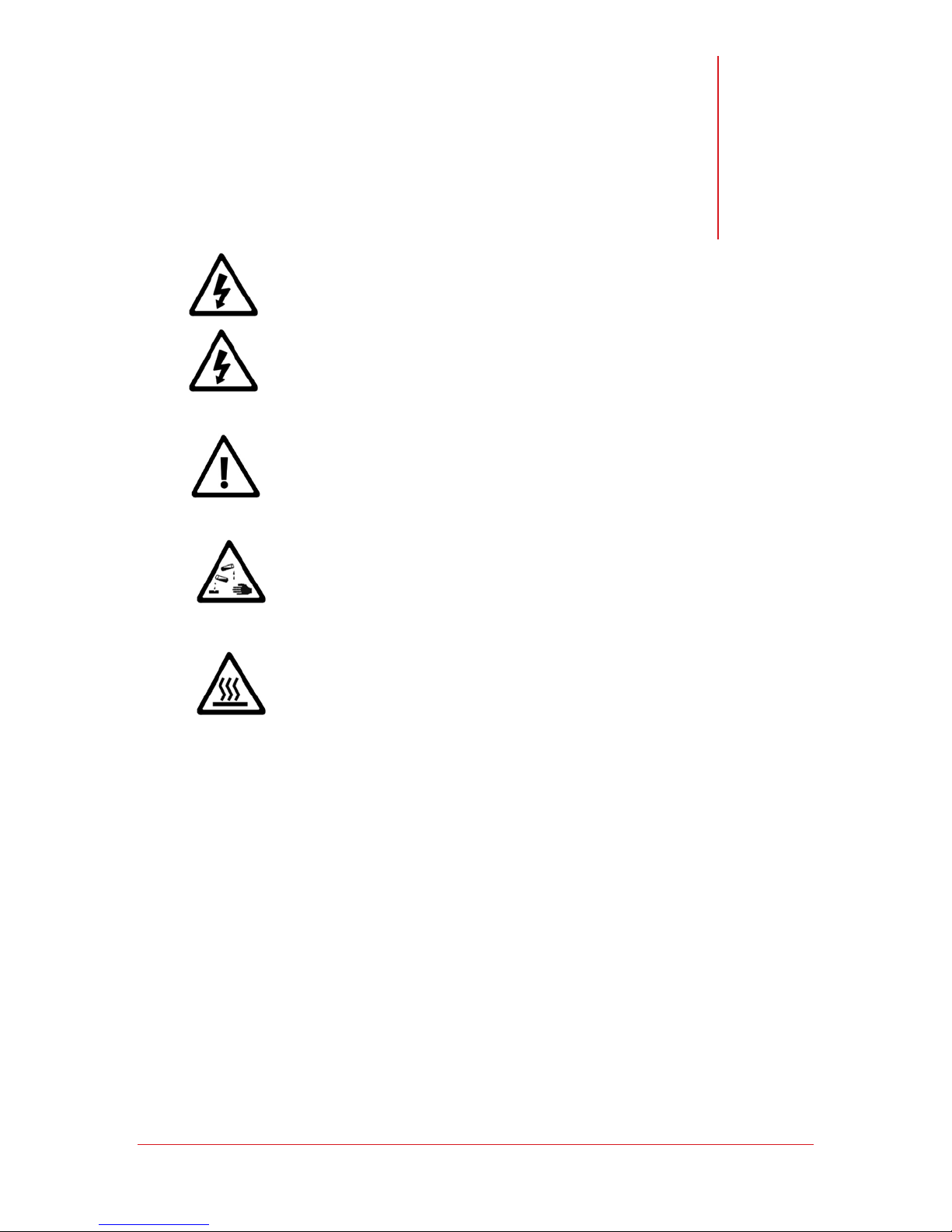
Chapter
6
Maintenance
Warning! Hazardous voltages. Risk of electric shock. Disconnect all
power before servicing this unit. Refer servicing to qualified service
personnel.
Caution! Power supply phases to this unit must be in correct sequence
Notice! Only qualified personnel should perform maintenance on the
refrigeration system itself, and only EPA certified technicians may
evacuate or charge refrigerants.
Hazardous Material/Contact Hazard! The chemicals used in this unit are
contained within fully enclosed systems. No maintenance activities
involving the refrigeration system are to be performed by the end-user.
Hot Surface! The compressor and associated tubing in the lower portion
of the unit are likely to be hot and pose a potential burn hazard.
© SP Industries, Inc. MNL-008-A Rev. 009
42
Page 43
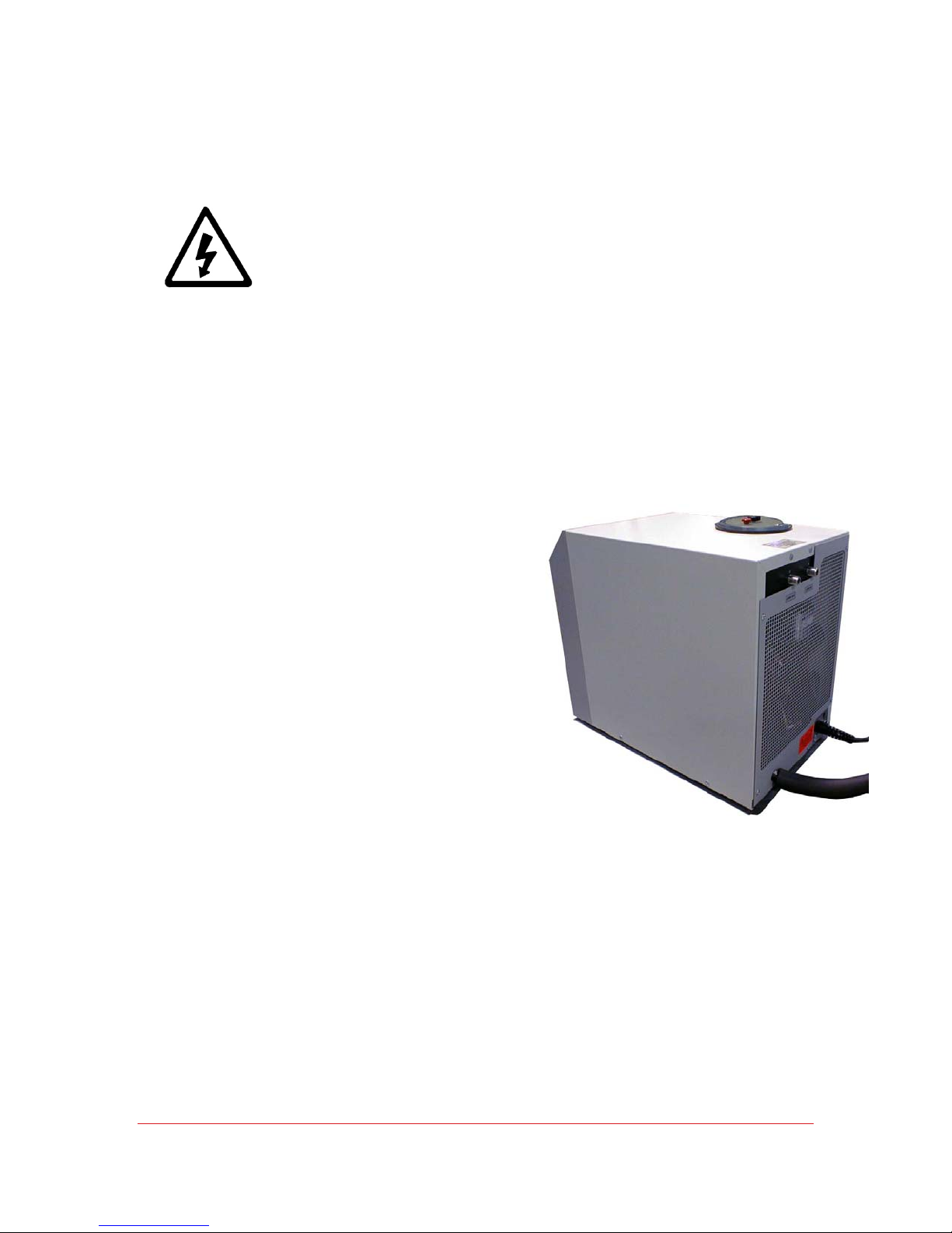
Operator’s Manual: RS Series Chiller Chapter 6: Maintenance
Lockout/Tagout Procedure
To prevent accidental or unauthorized starting of this unit during
maintenance, disconnect the power cord and install an appropriate lockout
device on the end of the power cord. The necessary equipment should be
available to allow the user to comply with OSHA 29 CFR 1910.147 (Control
of Hazardous Energies, Lockout/Tagout) and 29 CFR 1910.331-335
(Electrical Safety - Related Work Practices) as related to lockout/tagout.
This unit is provided with a line cord with a standard NEMA 5-15P or 6-15P. Lockout
of the equipment can be accomplished at the end of the equipment’s power cord.
Removal of Panel
•Ensure the line cord is unplugged and
tagged-out.
•Loosen and remove screws along edges
of the rear panel and grill.
•Remove reservoir lid
•Pull off panel back and up to remove.
•Place it out of the way.
© SP Industries, Inc. MNL-008-A Rev. 009
43
Page 44
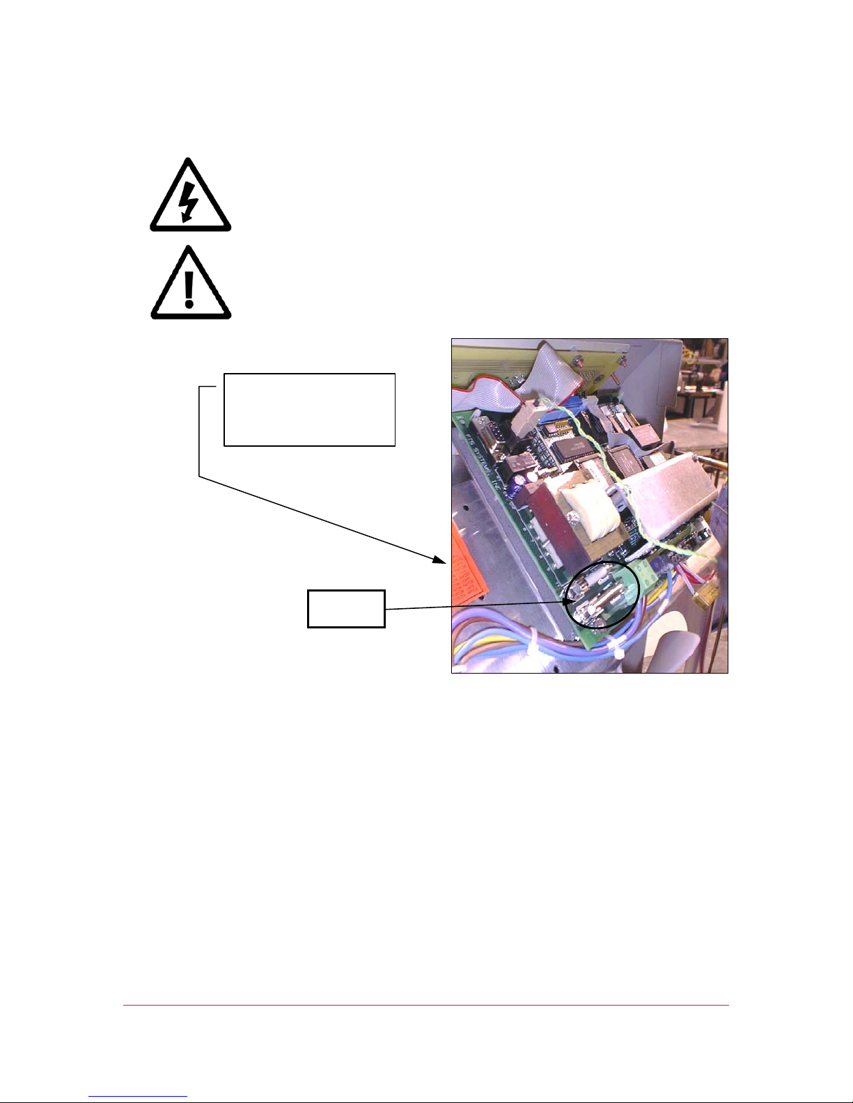
Operator’s Manual: RS Series Chiller Chapter 6: Maintenance
Fuse Replacement
Warning! Hazardous voltages. For continued protection against risk of
fire or shock, replace fuses only with those of same type and rating.
Qualified service personnel must perform replacement.
Notice! Only qualified personnel should perform maintenance on the
system.
NOTE: Replace Fuses
with only the type and
rating specified by the
orange label.
Fuse
Location
© SP Industries, Inc. MNL-008-A Rev. 009
44
Page 45

Operator’s Manual: RS Series Chiller Chapter 6: Maintenance
Cleaning
Warning! Hazardous voltages. Risk of electric shock. Disconnect all power
before servicing this unit. Refer servicing to qualified service personnel.
Notice! Only qualified personnel should perform maintenance on the
system.
Caution! Proper safety equipment such as eye and face
protection, gloves and dust mask should be used.
The following procedure should be followed on a routine basis,
from weekly to monthly depending upon the operating
environment.
•Disconnect electric utilities.
•Wipe down all exterior cabinet surfaces with a damp cleaning cloth.
•Check switch for proper operation.
•Vacuum dust from the refrigeration condenser as well as all screens and
openings.
•Remove cabinet panels.
•Blow compressed air systematically from the top to bottom. Let air settle for
several minutes and repeat.
•Check for areas that have frosted during operation and insulate as required.
•Replace cabinet panels.
•Connect electric utilities.
© SP Industries, Inc. MNL-008-A Rev. 009
45
Page 46
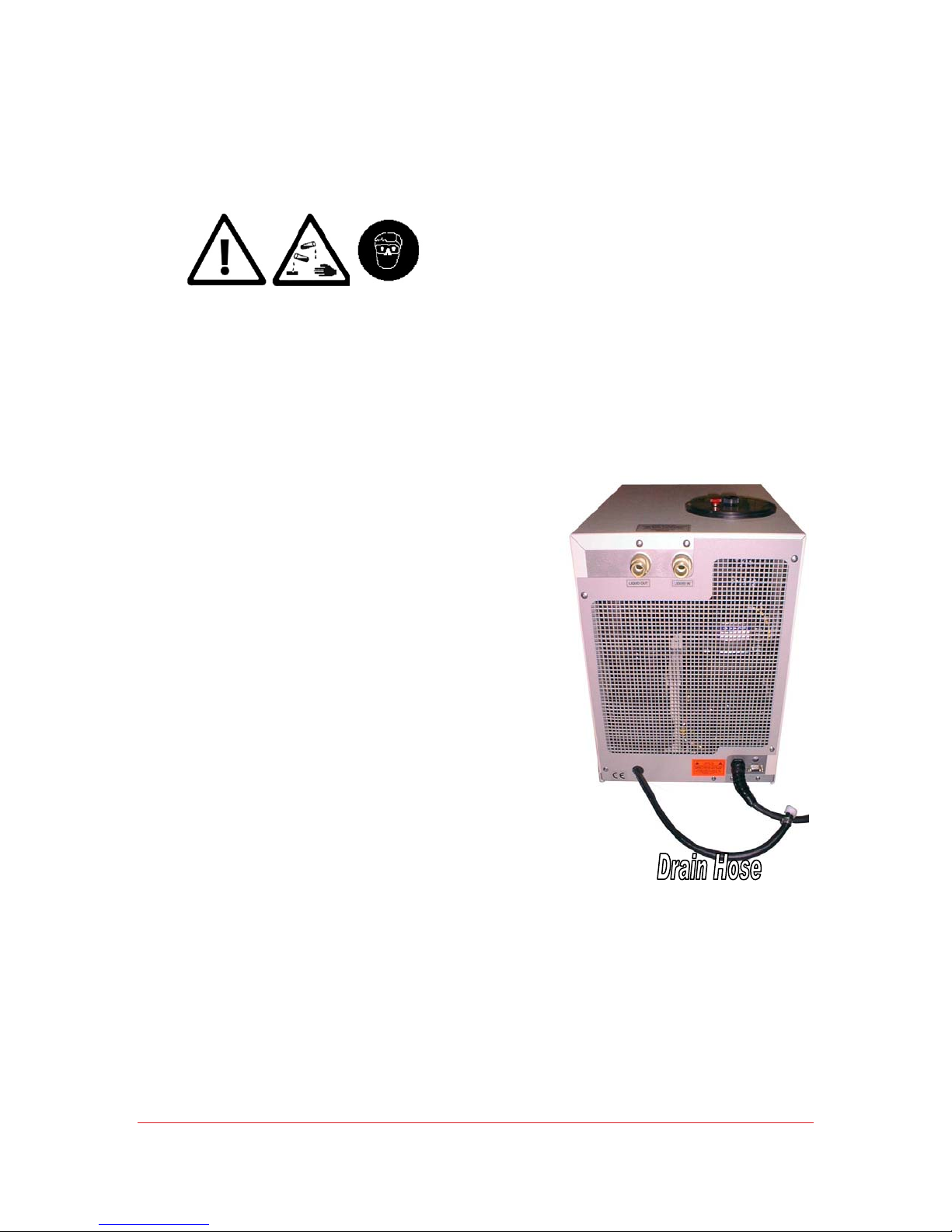
Operator’s Manual: RS Series Chiller Chapter 6: Maintenance
Draining Fluid
Always use caution when handling fluids, filling or draining the system reservoir, or working in or
around the chiller. Always wear protective eyewear when operating the chiller.
The user may need to drain the unit for any number of
reasons: to replace the fluid, to change the type of fluid
used, during maintenance, during repairs, etc.
To drain the unit:
•Place a large low pan underneath the black
drain hose (the hose pulls out for easier
access)
•With a screw driver loosen the clamp on the
end of the drain hose
•Remove the plug.
•
When the unit is completely drained:
•Replace the plug.
•Reposition and tighten the hose clamp.
© SP Industries, Inc. MNL-008-A Rev. 009
46
Page 47
Chapter
7
Troubleshooting
NOTICE!
EPA certified technicians should evacuate or charge refrigerants.
PROBLEM POSSIBLE CAUSE SOLUTIONS
UNIT WILL NOT
START
PUMP WILL
NOT START
Only qualified personnel should perform maintenance on the refrigeration system, and only
Power is not connected properly Have electrician check power connections
Breaker at the wall is in the "off" position Turn breaker "on".
Fuse has blown Have qualified person check and replace fuse.
Power is not connected properly. Have electrician check power connections.
Breaker at the wall is in the "off" position Turn breaker "on".
Pump is not primed Prime pump.
Impeller jammed Verify that motor is getting voltage and that the voltage
is correct. If the fluid freezes it will jam the pump
impeller
Pump motor has overheated The pump motor is provided with a thermal overload
protection. If it overheats, the pump will shut down; it
will restart when the motor has cooled down. This is
usually a result of the pump being overworked. Insure
that the viscosity of the fluid being used remains <20
centistokes. Check solutions under "Fluid Flow is
Inadequate".
Pump motor has burned out Very unlikely! If all reasons listed above are not the
cause and the pump has voltage to it, the pump motor
is no good. Contact factory for a new motor.
© SP Industries, Inc. MNL-008-A Rev. 009
47
Page 48
Operator’s Manual: RS Series Chiller Chapter 7: Troubleshooting
UNIT NOT
COOLING
PROPERLY
Temperature setting above fluid
temperature
Viscosity of fluid is too
High for intended temperature range.
Ambient temperature too high. To meet specifications the room air temperature must
Plumbing incorrectly connected to
process.
Heat load is above unit’s rating Check so see that all lines have adequate insulation,
Adjust temperature setting to the proper setting
Change fluid.
be 72°F/22°C. The capacity of the cooling system and
the maximum low temperature will degrade as the
temperature increases
Check that "LIQUID OUT" port of system is connected
to inlet of system to be cooled, and that "LIQUID IN" is
connected to outlet of system to be cooled
and that there are no local sources of heat that may
be contributing to the load.
Refrigerant leak. Enlist a qualified, certified refrigeration technician to
connect gauges and check static charge. If this
confirms a leak, have the system leak checked, repair
leak, and recharge system to proper level.
Contact the FTS Service Dept. for assistance in leak
checking and charging the system if needed.
EMPERATURE
T
ONTROLLER
C
WILL NOT
ONTROL
C
EMPERATURE
T
Controlling but
not ve r y well?
See controller
instructions for
PID tuning
.
FLUID FLOW IS
INADEQUATE
Ball valve is closed Open ball valve
Fluid flow is inadequate See "FLUID FLOW IS INADEQUATE
Cooling valve is sticking Adjust temperature set point to cycle the cool indicator
on/off. This should result in a 'clicking' sound from
inside the machine
Open Sensor. Measure resistance of sensor. It should be
approximately 100 ohms. If it is not, a new sensor is
needed. Contact Service Dept. for new sensor
Connection on controller has come loose Check all connections on controller inside the unit. If
any are loose or disconnected, reconnect them
Low voltage to solenoid valves The controller is operating properly but because of
inadequate voltage to solenoid valve, the valves are
not opening and closing as needed. Correct voltage
supplied to the unit.
Defective solenoid valve The controller operating properly, but the solenoid
valve is not responding because of a defect. Replace
coil. If problem still persists contact service
department
Viscosity of fluid is too
high for intended temperature range
Pump screen blocked
(if using a high pressure pump such as
HPP2)
Ball valve is closed Open ball valve
Plumbing lines have become restricted or
broken
Change fluid to a fluid with lower viscosity.
The inlet to the pump has a screen filter that is
accessed by removing the insulation from the pump
and removing the large nut on the pump housing.
Check plumbing lines and repair as necessary
© SP Industries, Inc. MNL-008-A Rev. 009
48
Page 49
Operator’s Manual: RS Series Chiller Chapter 7: Troubleshooting
REFRIGERATION
WILL NOT START
REFRIGERATION
CUTTING OUT
PUMP IS
MAKING LOUD
NOISE
Restrictions in the system will not
allow needed flow with supplied pump
Impeller of pump has been damaged Remove pump and check impeller, contact factory for
Pump motor has overheated The pump motor is provided with a thermal overload
Pump motor has burned out. Contact service department for new pump motor
“0/1" switch was not pressed Press “0/1" button. Fluid pump starts first.
Voltage is inadequate. The compressor must have adequate voltage to start.
Ambient too warm The unit is designed for operation in an ambient
Fan not working Check the fan for rotation. If the fan is not rotating
Condenser blocked. The finned condenser requires adequate airflow to
Blocked filter screen
(on high pressure pumps only)
Fluid freezing or icing Make sure that there is no ice in the fluid. Straight
Use larger line sizes. Replace pump with pump
capable of supplying needed flow with the given
plumbing restrictions. Check with factory for warranty
implications
replacement pump or impeller. Determine cause of
damage and correct cause to prevent future damage
protection. If it overheats, the pump will shut down; it
will restart when the motor has cooled down. This is
usually a result of the pump being overworked. Check
the above items to see if they are causing the motor to
overheat
Refrigeration starts several seconds later
Check voltage when power is applied to the system. If
voltage is not within +/- 5% of the system rated
voltage, contact the electrical department to have the
voltage corrected
environment of 72°F/22°C. Temperatures over
80°F/27°C may cause the compressor to overheat.
check:
- AC supply to the fan.
- For blockage.
- Excessive dirt/dust.
provide cooling. Make sure that the finned surface is
6" away from the wall and not clogged with dust
Enlist a qualified technician to remove filter screen by
cutting back insulation and removing large nut on
pump housing.
water should not be used below 5°C. For lower
temperature operation mix with glycol.
NO HEATING
Standard
Fluid operating above overtemp set
point.
models do not
have heaters
and rely on the
Overtemp sensor open or not making
good contact.
load for the
addition of heat.
© SP Industries, Inc. MNL-008-A Rev. 009
Cooling valve sticking open Adjust the temperature set point to turn the cool
49
The overtemp is factory set for protection of the
equipment. DO NOT READJUST WITHOUT FTS
SERVICE AUTHORIZATION.
Verify that the heater is NOT getting AC
indicator on/off. As the light
As the light alternates, the valve clicks open/close.
This should regulate the temperature at setpoint.
If not, the valve/coil must be replaced.
Page 50

Service
Maintenance and troubleshooting of your FTS equipment should be performed only by a
trained, qualified technician.
If you require service on your unit please contact:
FTS
Service Department
3538 Main Street, PO Box 158
Stone Ridge, N.Y. 12484
Telephone: 845-687-0063 or 877-548-4666
FAX: 845 687-0024
Email: [email protected]
FTS Warranties and Service Agreements
The FTS Service Division was founded in January of 1971. Our technicians are fully trained
to service all electrical, refrigeration, liquid, vacuum, air, and vapor control systems
manufactured and sold by FTS. We service all FTS products throughout the world from our
home office located at the FTS manufacturing facility in Stone Ridge, New York.
In addition to factory support personnel, we have a worldwide network of qualified service
organizations ready to accommodate you and your service needs.
Customer satisfaction is our number one priority. Our goal is to provide the finest quality
service promptly at the best price possible. We recognize that a satisfied customer is our
most valuable asset!
A timely solution to a service problem is best achieved by establishing good communication
with the FTS Service Division. We will furnish the appropriate qualified service support group
for your area. Should you require repair services or parts for your FTS equipment please
contact us at your convenience. We will discuss your requirements and suggest the best
means to get you back on line as fast as possible.
Chapter
8
© SP Industries, Inc. MNL-008-A Rev. 009
50
Page 51

Operator’s Manual: RS Series Chiller Chapter 8: Service & Warranties
Standard Warranty
The FTS standard domestic warranty follows. This warranty covers parts and labor for a
period of one year, commencing the date of invoice, for any repairs deemed resultant of a
defect in materials and/or workmanship by FTS, F.O.B. Stone Ridge.
Any factory approved changes or extensions to this warranty should be received in writing
from FTS and filed with this warranty. If your system is eligible for coverage, please review
this warranty thoroughly and contact the FTS Service Division with any questions you may
have. If your system is not covered by our standard warranty, or you are seeking optional or
additional coverage, see sections below for service plans offered.
Covered:
• Parts and labor for a period of one (1) year from date of delivery. Any part found defective
will be either repaired or replaced at FTS discretion, free of charges by FTS, at Stone
Ridge, N.Y.
• On site labor if repairs require that FTS personnel travel to the equipment.
• Necessary parts and reasonable labor charges, if FTS agrees that local service is
preferable. These parts and labor charges are subject to written approval prior to initiating the
repair.
• Travel time, mileage, travel and transportation expenses expended by FTS personnel if
repairs require on-site labor.
• Transportation of the equipment for repair.
Not Covered:
• FTS is not responsible for incidental or consequential damages, or damage resulting from
negligence.
This writing is a final and complete integration of the agreement between the customer and
FTS. FTS makes no other warranties express or implied, of merchantability, fitness or
otherwise, with respect to the goods sold under this agreement, which extend beyond the
description of this limited warranty.
FTS will have the right to inspect the equipment and determine the repairs or replacements
necessary. The customer will be notified within a reasonable time of any damages incurred
that are not covered by this warranty prior to initiation of any such repairs.
Any customer modification of this equipment, or any repairs undertaken without the prior
written consent of FTS will render this limited warranty void.
© SP Industries, Inc. MNL-008-A Rev. 009
51
Page 52

Operator’s Manual: RS Series Chiller Chapter 8: Service & Warranties
Service Options
Extended Warranty:
This plan is an extension to the original new purchase warranty. You may extend the original
warranty for one or two years total coverage. This plan does not provide Preventative
Maintenance, nor does it cover travel or any freight expenses incurred.
Preventative Maintenance:
This plan provides our customers with one or two onsite visits per year. We would perform a
thorough preventative maintenance on your FTS equipment. You will be provided with a PM
checklist and a certificate of calibration, which is traceable to N.I.S.T. The purchase of this
plan also provides discounted parts and labor rate for additional service if deemed necessary
at the time of the PM.
Service Contract:
Service contracts (SC) are available post-expiration of any warrant period (standard or
extended). SCs provide companies a plan which includes travel, labor, and priority response
time. Any necessary parts are provided at a discounted rate. Two levels (silver and gold) are
available for varying customer needs.
Contact FTS Service at (845) 687-0063 or (877) 548-4666 for details.
© SP Industries, Inc. MNL-008-A Rev. 009
52
Page 53

Operator’s Manual: RS Series Chiller Chapter 8: Service & Warranties
Return of FTS Equipment
If it is necessary to return the equipment to our factory, please contact the FTS Service
Division at (800) 722-7721 for a Return Authorization (RA) number, and instructions on
returning the unit. Please provide the model number, serial number, and order number.
After receiving an RA number, return the unit, freight prepaid, to the following address:
FTS, Inc.
3538 Main Street
PO Box 158
Stone Ridge, N.Y. 12484 U.S.A.
Attn: Service Division RA# _________
Make sure the RA number and the declared value of the unit is plainly marked on your
shipping label.
FTS will refuse any equipment returned without a RA number, without freight prepaid, or with
an expired RA number. This number is valid for 30 days; if your RA number expires you must
request a new number.
Before working on systems that are not under warranty, the Service Division will provide you
with an estimate of the time and cost for the repair of your unit. No work will be started until
FTS receives a hardcopy of your purchase order for the repair work. This also applies to
warranty work when the customer is responsible for the shipping costs.
If your repair is urgent, you may authorize an emergency repair fee, which guarantees priority
service.
Unless you specify otherwise, we will return the repaired unit F.O.B. from our Stone Ridge,
New York factory, via ground transportation.
© SP Industries, Inc. MNL-008-A Rev. 009
53
 Loading...