

Page 1
EXTREME ENVIRONMENTS. EXTREMELY RELIABLE.
700-Bubbler-Man Rev 2 14 Aug 2017
Bubbler
User Manual
1.800.548.4264 | www.ftsinc.com
Page 2

Contact Information
Canadian Headquarters:
1065 Henry Eng Place
Victoria, BC | V9B 6B2 | Canada
www.ftsinc.com
Toll-free: 1.800.548.4264
Local: 250.478.5561
Technical support portal: http://support.ftsinc.com
Email: [email protected]
Page 3

Contents
CHAPTER 1 GENERAL ................................................................................................ 1
1.1 INTRODUCTION ................................................................................................................................................................... 1
1.2 DISPLAY AND KEYPAD ..................................................................................................................................................... 2
1.3 CONFIGURING THE BUBBLER ......................................................................................................................................... 2
1.4 FIRMWARE UPDATES ........................................................................................................................................................ 3
CHAPTER 2 INSTALLATION ....................................................................................... 4
2.1 PRIOR TO PROCEEDING TO THE SITE .......................................................................................................................... 4
2.1.1 Equipment ................................................................................................................................................................. 4
2.2 SITE SELECTION ................................................................................................................................................................... 4
2.3 MOUNTING ........................................................................................................................................................................... 4
2.4 CONNECTORS AND WIRING ........................................................................................................................................... 4
2.4.1 SDI-12 Connections ................................................................................................................................................ 5
2.5 DESICCATOR ......................................................................................................................................................................... 5
2.6 CONNECTING AND INSTALLING THE ORIFICE LINE ............................................................................................... 6
2.6.1 Using the Swagelok® Fitting ............................................................................................................................... 7
2.7 POWER CONNECTIONS .................................................................................................................................................... 8
CHAPTER 3 BUBBLER INTERFACE AND MENUS ....................................................... 9
3.1 KEYPAD .................................................................................................................................................................................. 9
3.2 SCREENS, MENUS AND OPERATING THE USER INTERFACE ............................................................................... 9
3.2.1 Editing a Menu Item .............................................................................................................................................10
3.3 STATUS SCREEN ................................................................................................................................................................10
3.3.1 Fault ............................................................................................................................................................................10
3.4 CONDUCTING A MANUAL PURGE .............................................................................................................................10
3.4.1 Bleeding the Tank .................................................................................................................................................11
3.5 CONFIGURING THE BUBBLER USING THE BUBBLER INTERFACE ....................................................................12
3.6 SETTING THE STAGE ........................................................................................................................................................12
3.7 SETUP MENU ......................................................................................................................................................................13
3.8 DIAGNOSTICS.....................................................................................................................................................................13
3.8.1 Updating Firmware ..............................................................................................................................................14
CHAPTER 4 CONFIGURATION USING AXIOM DATALOGGER INTERFACE ........... 15
4.1 SETUP GENERAL INFORMATION .................................................................................................................................16
4.2 SENSOR TAB .......................................................................................................................................................................17
4.3 STAGE TAB ..........................................................................................................................................................................17
4.4 MECHANICAL TAB ............................................................................................................................................................18
i
Page 4

4.5 PURGE TAB ..........................................................................................................................................................................19
4.6 SAVE CONFIGURATION ..................................................................................................................................................20
4.7 BUBBLER SENSOR SCREEN ............................................................................................................................................20
4.7.1 Conduct a Manual Purge ....................................................................................................................................21
4.7.2 Set Stage and Calculate/Clear Offset .............................................................................................................21
CHAPTER 5 SDI-12 COMMANDS ............................................................................. 25
5.1 STANDARD SDI-12 MEASUREMENT COMMANDS ...............................................................................................25
5.1.1 SDI -12 Measurement Command Codes ......................................................................................................26
5.2 EXTENDED (X) COMMANDS .........................................................................................................................................27
5.2.1 Required Formatting Elements .......................................................................................................................27
5.2.2 X Commands List...................................................................................................................................................27
APPENDIX A SPECIFICATIONS .................................................................................. 30
APPENDIX B TROUBLESHOOTING GUIDE ................................................................ 31
B.1 MECHANICAL INDICATORS ..........................................................................................................................................31
B.2 BUBBLER STATUS SCREEN FAULT INDICATORS ....................................................................................................31
B.3 HEALTH STATUS/ERROR INDICATORS ......................................................................................................................32
B.3.1 MANAGING HEALTH STATUS INDICATORS .................................................................................................32
B.3.2 DETERMINING MULTIPLE HEALTH STATUS INDICATORS ......................................................................33
APPENDIX C PARTS AND ORDERING INFORMATION ............................................. 34
DOCUMENT REVISION HISTORY ................................................................................ 35
ii
Page 5
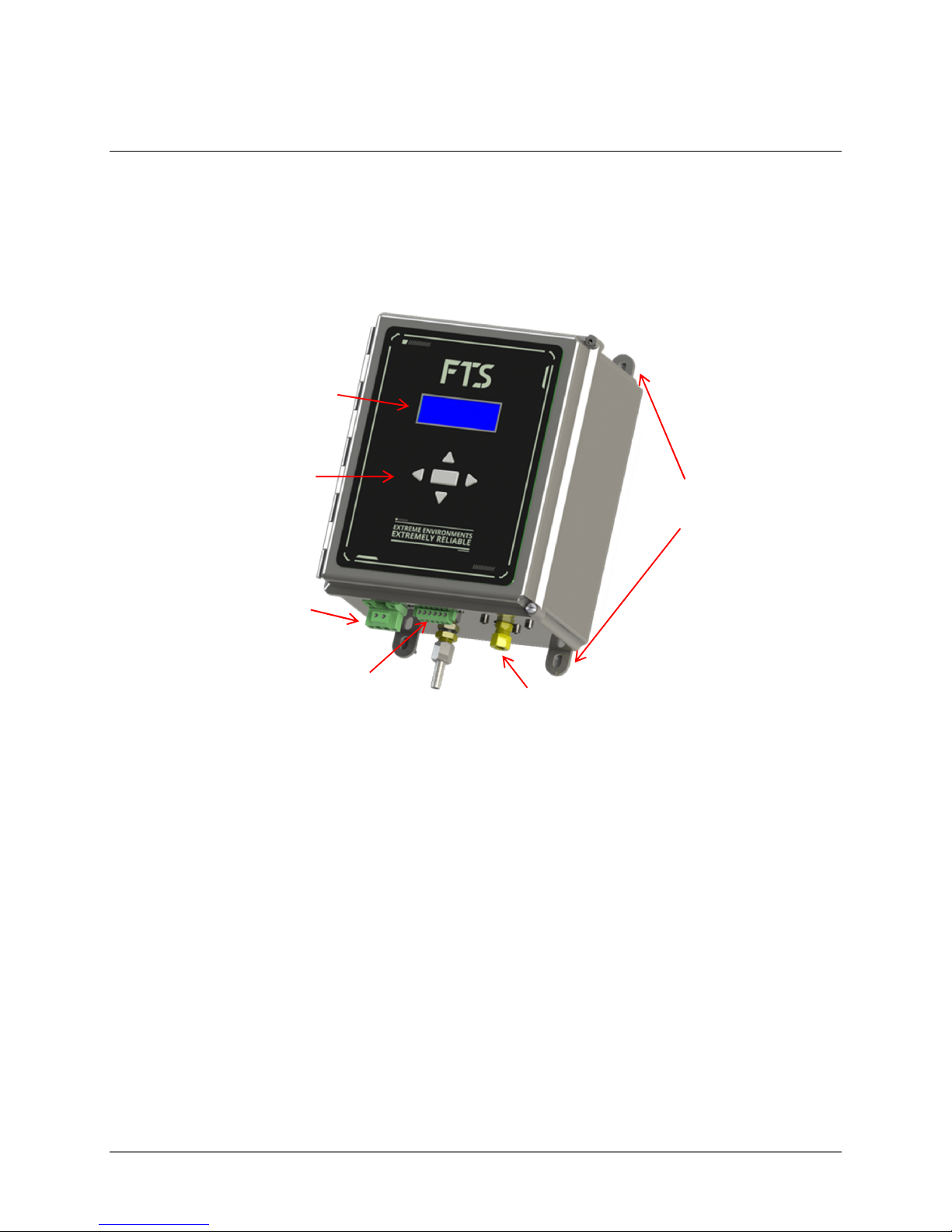
Air Intake
Display
Keypad
Chapter 1
GENERAL
1.1 INTRODUCTION
The FTS Bubbler is an SDI-12 user configurable system for accurately measuring water stage in streams
and reservoirs using pressure differentials. It is a self-contained, sealed system that includes an air
compressor, control electronics and a high accuracy pressure sensor for measuring water levels. It can
be connected to a data collection platform (DCP) using the SDI-12 interface for data logging capability
Mounting
plates
Power
Connector
SDI-12 Data
Connector
Compressor
Outlet/Orifice Line
Connection
Figure 1-1: Bubbler components
The system forces air at a continuous rate through an orifice line, the end of which is mounted at a
known, fixed position. A sensor measures the pressure required to maintain the air flow down the
orifice line such that bubbles emerge from its end, compares that to atmospheric pressure, and
computes the stage level (water depth). Any change in water level causes the air pressure in the
orifice line to vary resulting in updated stage levels.
FTS’ proprietary design allows for a larger orifice (18 times larger than the standard metering valve
orifice of 0.035mm). Not only does this minimize fouling of the manifold but it also allows the purge
to flush particulates throughout the entire system from the compressor valve to the orifice line end
fitting. The purge is achieved without bypassing a portion of the system, as systems which use a
metering valve must do. This results in highly accurate readings, even in environments with high
humidity or containing airborne particulates.
To maintain the integrity of the internal components, FTS suggests maintenance should be conducted
by factory trained personnel at the FTS factory.
700-Bubbler-Man Rev 2 14 Aug 2017 Page 1/35
Page 6
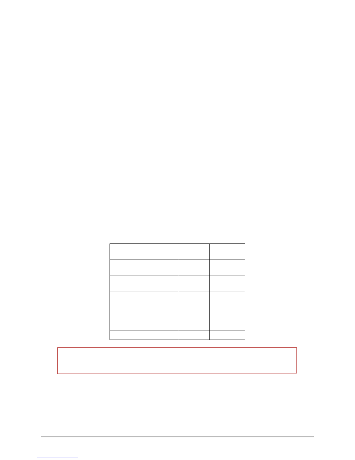
1.2 DISPLAY AND KEYPAD
The front panel has a display and keypad which is used to view information and perform specific
actions (purge, set stage, setup, and diagnostics). The display will normally be off in power save mode.
Pressing any key will display the status screen. The arrow keys are used to navigate through the
different functions and configuration parameters.
The front panel allows the user to do the following:
Set purge pressure
Conduct a manual purge
Manually bleed the tank
Set stage
Set stage units
Set bubble rate
Set averaging duration
Set temperature units
Set the SDI-12 address
Details of the interface and menu items are contained in Chapter 3.
1.3 CONFIGURING THE BUBBLER
The Bubbler can be configured through its front panel or through a data logger. However, certain
features, those which require a timer, can only be set through a data logger. Refer to Table 1-1.
Table 1-1: Configuration using Bubbler vs data logger
FUNCTION BUBBLER
Set stage
Set stage units
Set bubble rate
Set temperature units
Set averaging duration
Perform manual purge
Set scheduled purge
Set scheduled stage
collection
Set date and time1
IMPORTANT! The Bubbler will retain the last input configuration whether set through
the Bubbler or the data logger.
DATA
LOGGER
1
This sets the Bubbler’s date and time which is used on the time stamp of the Bubbler’s SD card. It does not
affect the time stamp of sent data or the timing of scheduled events as those are controlled by the data logger
and the telemetry in use. If not using an Axiom Datalogger and it is desired to maintain the integrity of the
Bubbler’s SD card timestamp, this will have to be manually set every 24 hours using the Set time and date Xcommand ( See section 5.2 )
700-Bubbler-Man Rev 2 14 Aug 2017 Page 2/35
Page 7

The Set Stage and Setup sub-menus on the Bubbler’s interface are used to configure the Bubbler.
Refer to Chapter 3 for details.
If the Bubbler is used with an FTS Axiom Datalogger, configuration is done through the Bubbler sensor
extension. See Chapter 4 for details.
If using a data logger other than the Axiom, configuration is done using the X-commands. Refer to
Chapter 5.
1.4 FIRMWARE UPDATES
Periodically, the Bubbler’s firmware may need to be updated. In that event, FTS will issue a
notification with instructions on how to conduct the update.
700-Bubbler-Man Rev 2 14 Aug 2017 Page 3/35
Page 8

Chapter 2
INSTALLATION
2.1 PRIOR TO PROCEEDING TO THE SITE
2.1.1 EQUIPMENT
Unpack the Bubbler and conduct a visual inspection for any signs of shipping damage. If any damage
is found, contact FTS Service and Support immediately. Retain the shipping container to transport the
Bubbler to the site or to return the unit to FTS should damage have occurred during shipping.
A 3/32” head size flathead screwdriver will be required for the screws on the terminal blocks. Ensure
you bring the required tools and hardware for mounting the Bubbler in accordance with your site
characteristics.
2.2 SITE SELECTION
The Bubbler should be mounted adjacent to the body of water to be measured, typically in a
hydrology shack or gauging house. The position of the Bubbler should allow for a continuous
downward run of the orifice line to its final termination point. The water should be relatively calm and
where sediment accumulations are not likely to block the orifice.
The orifice line with a terminating orifice should be laid out into the water so that the stream ward end
will remain in a fixed position and at a depth that will not be exposed at low stage. Should the orifice
line need to be installed in an area with high currents, it should be installed in a static tube.2
2.3 MOUNTING
The Bubbler should be firmly bolted to a vertical surface using the mounting plates located on the
corners of the enclosure. The connectors and outlets should be pointing down. The bottom of the
Bubbler should be free of obstruction so the orifice line has a free downward run. Ensure the orifice
line is not bent or crimped.
It is not recommended to mount the Bubbler so that it rests on a horizontal surface
such as a table top or shelf as this can bend the orifice line permitting moisture to
accumulate and prevent the correct operation of the device.
2.4 CONNECTORS AND WIRING
When installing the Bubbler connections, do not apply power until all other connections are made.
The following connections should be made:
1. Data connections (SDI-12)
2. Desiccant assembly
3. Orifice line
4. Power
2
Refer to USGS publications TM3-A7 Stage Measurement at Gaging Stations http://pubs.usgs.gov/tm/tm3-
a7/pdf/tm3-a7.pdf and TWRI_8-A2 “Installation and Service Manual for U.S. Geological Survey Meters”
http://pubs.usgs.gov/twri/twri8a2/html/pdf.html
700-Bubbler-Man Rev 2 14 Aug 2017 Page 4/35
Page 9
2.4.1 SDI-12 Connections
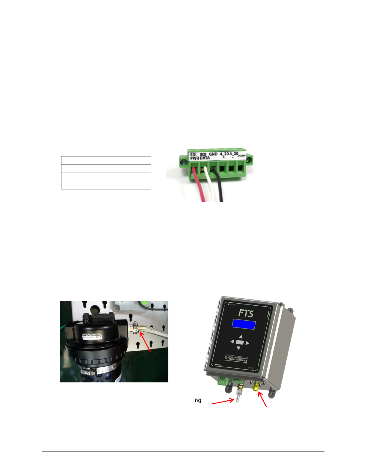
SDI-12 connections are made using the removable terminal block on the bottom of the Bubbler.
These connections are used to connect the Bubbler to an SDI-12 capable DCP, such as an Axiom
Datalogger.
The SDI-12 interface has connections for power (12 v), serial data, and ground. Connect the SDI-12
leads to the data logger in accordance with the manufacturer’s direction. Connect the flying leads
from the data logger to the Bubbler’s terminal strip as shown.
Insert the terminal block into the Bubbler’s connector port and secure.
Pin Description
1 12 volt line
2 Serial data line
3 Ground line
Figure 2-1: SDI-12 Connections
2.5 DESICCATOR
An external desiccator must be connected to prevent the accumulation of moisture in the compressor
manifold and throughout the system. The desiccator should be mounted close to the Bubbler to
minimize the length of the output hose. Ensure there are no kinks or bends in the output hose.
Connect the output hose from the desiccator to the inlet fitting on the Bubbler. Secure both ends of
the hose with a hose clamp. Follow the manufacturer’s directions with respect to handling, mounting,
maintenance, and disposal of the desiccator and desiccant.
Output hose
secured with
hose clamp
Desiccator
Figure 2-2: Desiccant and Orifice Line Connections
Inlet Fitting
(desiccant hose
connection)
Bubbler outlet
(orifice line
connection)
700-Bubbler-Man Rev 2 14 Aug 2017 Page 5/35
Page 10

2.6 CONNECTING AND INSTALLING THE ORIFICE LINE3
The orifice line should be black polyethylene 3/8” outer diameter, 1/8” inner diameter USGS approved.
The maximum length of the line should not exceed 1000 ft. There will be an induced error caused by a
pressure drop in lines which exceed the maximum recommended length.
The orifice line should be laid out and the run established and set up before connecting it to the
Bubbler.
The run should be as straight as possible in a continuous downward path to minimize moisture
collection in catenaries. No part of the line should be lower than the line exit in the water. The run
should terminate in a calm area.
Consider enclosing the line in a protective conduit to prevent damage from animals, vandals, etc.
The orifice line should be laid out in calm water and secured so that the stream ward end with the line
outlet will remain in a fixed position and at a depth that will not be exposed at low stage. The stream
ward end should be directed pointing down.
Should the orifice line need to be installed in an area with high currents, it should be installed in a
static tube.
DO:
Use only USGS approved line
Install the line outlet pointed downwards
in calm water
Ensure the line’s run is downward with no
catenaries or bows
Ensure no part of the line’s run is lower
DO NOT:
Face the stream ward end of the orifice
line facing upstream, downstream or
upwards
Mount the line outlet in turbulent water
or in the wake of an obstruction (boulder,
bridge footing etc.)
than the line outlet
Once the orifice line run is securely laid out, connect the orifice line to the Bubbler outlet (refer to
Figure 2-3) and secure it with the provided Swagelok® fitting.
3
For a detailed explanation of the installation of an orifice line and static tube, refer to USGS publications:
TWRI_8-A2: Craig, J.D, 1983, “Installation and service manual for U. S. Geological Survey manometers”: U.S.
Geological Survey Techniques of Water-Resources Investigations, book 8, chap. A2.
http://pubs.usgs.gov/twri/twri8a2/html/pdf.html
TM3-a7: Sauer, V.B. and Turnipseed, D.P., 2010 “Stage Measurement at Gaging Stations”: U.S. Geological Survey
Techniques and Methods, book 3, chap 7, sect A http://pubs.usgs.gov/tm/tm3-a7/pdf/tm3-a7.pdf
700-Bubbler-Man Rev 2 14 Aug 2017 Page 6/35
Page 11
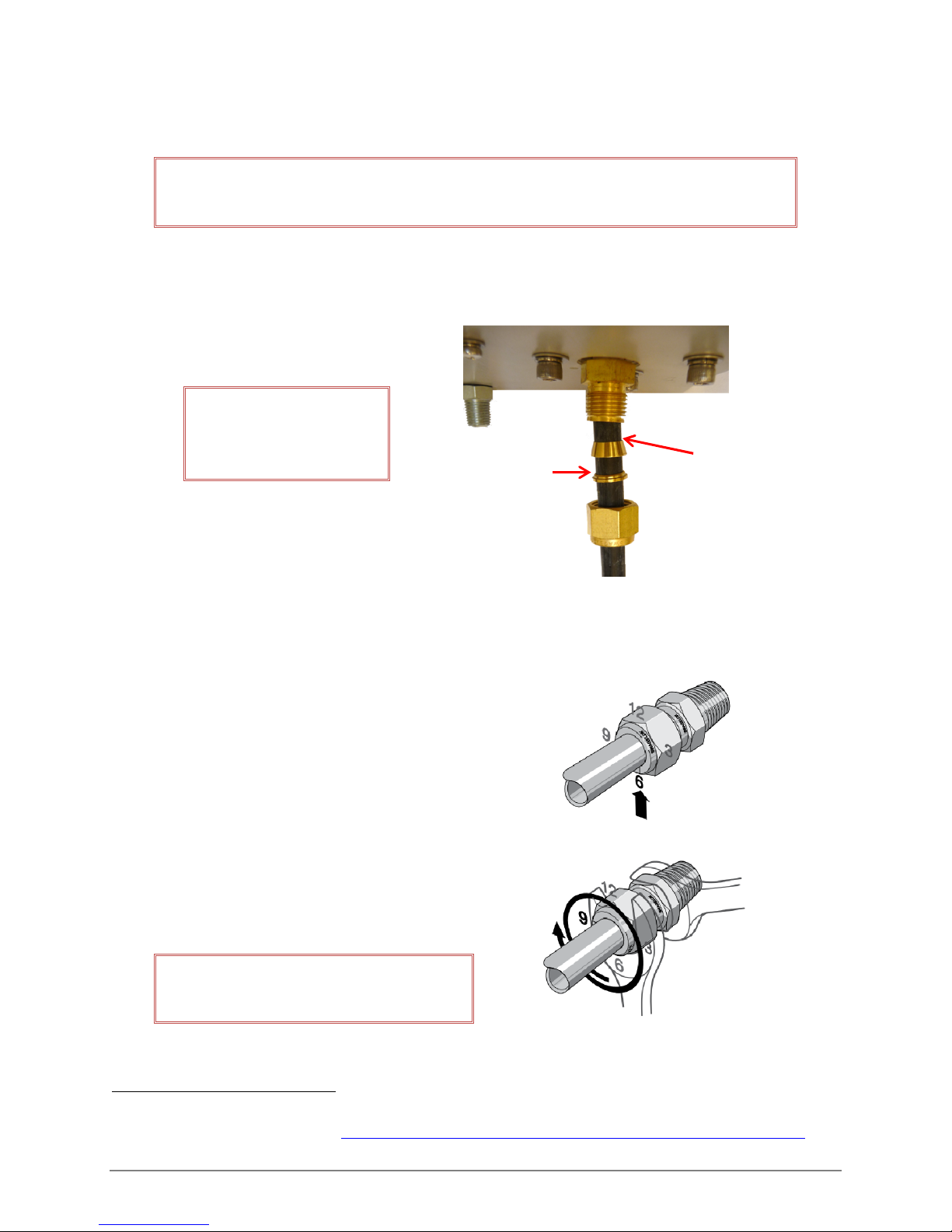
ferrule
2.6.1 USING THE SWAGELOK® FITTING4
IMPORTANT! Always depressurize the system prior to assembling/disassembling the
Swagelok fitting.
ASSEMBLY:
IMPORTANT! Ensure the
Swagelok fitting ferrules
are oriented as shown
Stepped down
portion of back
Tapered
section of
front ferrule
Figure 2-3: Swagelok fitting orientation
1) Place the nut and ferrules on the line as shown in Figure 2-3 and fully insert the line
into the Bubbler outlet.
2) Screw the nut on until finger tight.
3) Mark the nut at the 6 o’clock position.
4) Hold the Bubbler outlet steady with a wrench, and
use another wrench to tighten the nut one and a
quarter turns (pass the 6 o’clock position once and
stop at the 9 o’clock position).
DO NOT twist the Bubbler outlet.
Only turn the nut.
DISASSEMBLY
4
For a detailed explanation of installing Swagelok fittings refer to “An Installer’s Pocket Guide for Swagelok Tube
Fittings” on the Swagelok website. https://www.swagelok.com/downloads/webcatalogs/en/ms-13-151.pdf
700-Bubbler-Man Rev 2 14 Aug 2017 Page 7/35
Page 12
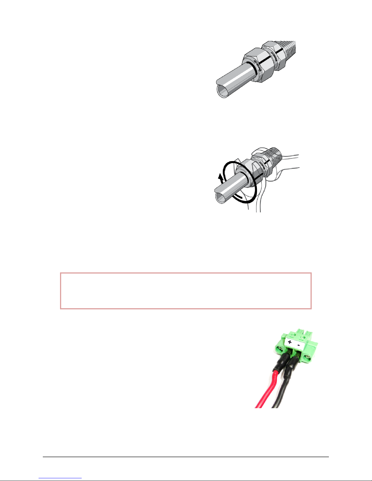
1) Mark a line along the back of the nut and Bubbler
outlet. These marks will be used to return the nut to
this position.
2) Use two wrenches as shown in Step 4 of the
assembly directions to loosen the nut.
3) Once maintenance is complete, replace the nuts and
ferrules, and re-insert the line as shown in Step 1 of
the assembly instructions.
4) Using the wrenches as shown in Step 4 of the
assembly instructions, turn the nut to the marked
position. At this point, resistance will increase.
Tighten the nut slightly.
2.7 POWER CONNECTIONS
The Bubbler requires a dedicated +12V power source to operate. This is normally supplied by an
external lead-acid battery. Although the Datalogger supplies some power through the SDI port, it is
only enough to view and operate the Bubbler’s screen. It is insufficient to run the compressor.
IMPORTANT! If the Bubbler is sharing an external battery source with other
equipment, the combined power draw will need to be considered when calculating
the site’s power budget and power requirements.
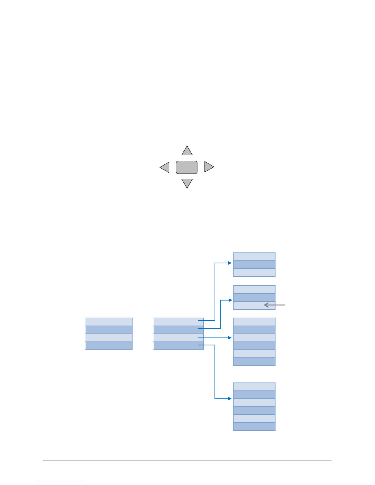
To connect the power cable:
1) Remove the power terminal block from the port
2) Secure the power wires to the appropriate pins (positive and
negative – see Figure 2-4).
3) Connect the power cable to the power source (positive to
positive, negative to negative).
4) Re-insert and secure the power terminal block.
700-Bubbler-Man Rev 2 14 Aug 2017 Page 8/35
Figure 2-4: Power
Connections
Page 13
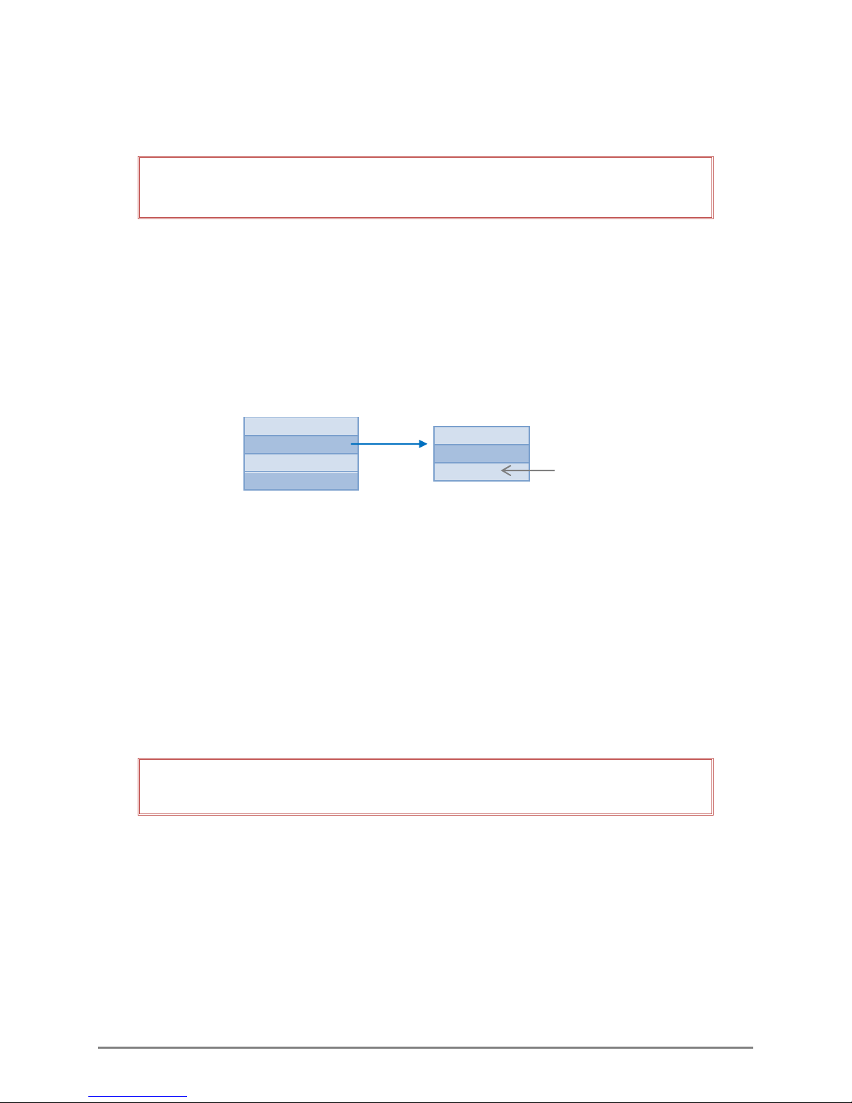
Up
Chapter 3
BUBBLER INTERFACE AND MENUS
The front panel has a display and keypad which is used to configure the Bubbler. When power is
supplied, the start-up screen will display for about 5 seconds before the Status Screen is displayed.
After three minutes of inactivity, the display will enter low power mode and blank out. Pressing any
button on the keypad will display the status screen.
3.1 KEYPAD
The keypad consists of the following buttons used to navigate through the different screens and
menu items:
Left
Select/
Accept
Down
Right
Figure 3-1: Keypad
3.2 SCREENS, MENUS AND OPERATING THE USER INTERFACE
The following diagram illustrates the different screens and menus.
STATUS SCREEN
SITE/FAULT *
STAGE
OFFSET
TANK PSI
MAIN MENU
PURGE
SET STAGE
SETUP
DIAGNOSTICS
* Normally the Status screen will
display the Site’s name. If it
indicates FAULT, the diagnostics
screen will provide details of the
fault.
SUB-MENUS
PRESSURE
PURGE
BLEED
STAGE
UNITS
SLOPE
SITE
ADDRESS
RATE
TEMP F/C
AVG DUR
SDCARD
BATTERY
TEMP
VERSION
UPDATE
DATE
TIME
Only shows
when custom
units are selected
700-Bubbler-Man Rev 2 14 Aug 2017 Page 9/35
Figure 3-2: Menu tree
Page 14

To display the Main Menu press the Select button.
Use the up and down arrows to move the double arrow symbol to the desired menu item.
Press the right arrow to bring up the sub-menu.
Use the up and down arrows to scroll through the sub-menu items
Press the left arrow to return to the previous menu.
Note that only four lines of the menu can be displayed on the screen, so you must use the up and
down arrows to view all items in longer menus.
3.2.1 Editing a Menu Item
Navigate to the item you wish to edit. It will be indicated by the double arrow symbol. Press the
Select/Accept button. The field that can be edited will flash. Use the up and down arrows to input the
desired number, symbol or letter. The right and left arrows will move the cursor to the next field to be
edited. Press the Select/Accept to save the changes.
3.3 STATUS SCREEN
The Bubbler’s status screen will display the site identification or any faults, the latest stage
measurement, the calculated offset and the tank PSI. Note that if a custom slope was used to calculate
the stage, the displayed unit of measurement will be “cu” (to designate custom).
When the status screen is displayed, pressing the right arrow on the keypad will initiate a fresh stage
reading.
3.3.1 FAULT
The FAULT display line can only show a single fault. Possible faults are prioritized, with the
understanding that a higher priority fault is normally the cause of lower priority faults (e.g. an
apparent compressor fault is caused by a battery fault). The priority of faults (highest to lowest) is:
BATTERY
TEMPERATURE
LINE_BLOCK
LINE_HIGH
3.4 CONDUCTING A MANUAL PURGE
PURGE
SET STAGE
SETUP
DIAGNOSTICS
Figure 3-3: Purge sub-menus
PRESSURE
PURGE
BLEED
700-Bubbler-Man Rev 2 14 Aug 2017 Page 10/35
Page 15

If the line becomes obstructed by silt, dirt or other debris, or water has accumulated in the line, the
line must be cleared. This is done by conducting a purge. No readings can be taken during the purge.
Input the desired pressure for the purge. The pressure range is 20-90 psi; the default setting is 90 psi.
The set purge pressure must be greater than the running tank pressure for the purge to take place. .
During a purge, the pump increases to the set purge pressure. Once the input purge pressure is
reached, the outlet valve is opened and the air is forced out until the tank pressure has dropped to 3
psi greater than the tank pressure was prior to purge. This prevents the ingress of water into the line.
Once the purge is complete, the tank pressure will equalize to the line pressure, and the bubble rate
will return to the settings prior to the purge.
To conduct a purge, select PURGE: START. Once the purge starts the screen will display
PURGE: STOP. The purge can be stopped during the process by selecting the PURGE: STOP option.
If PURGE: STOP is selected, the pump will stop, the tank pressure will decrease, and operations will
resume at previously configured settings. The increased pressure may cause the bubble size to
increase briefly until the tank pressure drops to the correct value.
If after 45 seconds of purging, the line cannot be cleared and the tank pressure is greater than 35 psi, a
compressor fault will be indicated in the status screen and the compressor will stop. The M and M1
commands will continue to be sent but will return values of -99999.0. The unit will continue to
attempt to bubble (the solenoid will continue to open and close) in the event the blockage does get
cleared and normal operations can resume.
If the tank pressure is less than 35 psi, the unit will continue bubbling at the set rate.
3.4.1 BLEEDING THE TANK
The tank pressure must be bled prior to some maintenance such as removing the orifice line or
swapping the bubbler. Once started, bleeding can be stopped by selecting the BLEED: STOP option.
If selected, the compressor will recharge the tank and operations will recommence.
Once the tank is bled, the power connector to the Bubbler should be removed until maintenance is
completed. Once maintenance is completed and power is re-established, operations will
recommence.
However, if power is not disconnected after the tank is bled and no further actions are taken,
operations will resume after 24 hours.
Normal Tank Bleed Procedure:
1) Start Bleed (bleeding will stop once tank empty)
2) Disconnect Power connector
3) Conduct maintenance
4) Replace power connector
700-Bubbler-Man Rev 2 14 Aug 2017 Page 11/35
Page 16
3.5 CONFIGURING THE BUBBLER USING THE BUBBLER INTERFACE
The Set Stage and Setup menus are used to configure the Bubbler.
IMPORTANT! After configuring, synchronize the Bubbler with the data logger by
issuing the aXCON! Command (see section 5.2).
The following variables can be set using either the Bubbler’s interface or through the data logger. The
Bubbler will retain the last input configuration regardless of which method is used.
Set stage
Stage units
Rate
Temperature units
Averaging Duration
3.6 SETTING THE STAGE
PURGE
SET STAGE
SETUP
DIAGNOSTICS
STAGE
UNITS
SLOPE
Only shows
when custom
(cu) units are
Figure 3-4: Set Stage sub-menu
Stage – Use the arrows to input the stage height. The Bubbler will use this value to calculate the
offset which will be displayed on the Status Screen.
Units – Use the up and down arrows to select the measurement units. The displayed Stage value will
automatically be converted to the equivalent stage value in the newly entered measurement unit.
MEASUREMENT UNITS
in (Inches)
ft (feet)
mm (millimeters)
cm (centimeters)
m (meters)
cu (custom)
HINT: When initially setting the Stage, enter the units of measurement first, and then
the desired stage value to prevent inadvertently leaving an erroneous stage height.
Explanation:
The desired stage measurement is 3.0 m. The currently entered stage measurement unit is in
feet (ft). When you enter Stage Height 3.0, the Bubbler now recognizes 3.0 ft as the stage height.
If you subsequently change the units to the desired meters (m), the stage height will be
converted to 0.914 (3.0 ft = 0.914 m).
If you do not return to the Stage function and re-enter the correct stage height, the input stage
value will remain as 0.914 m as opposed to the desired 3.0 m.
700-Bubbler-Man Rev 2 14 Aug 2017 Page 12/35
Page 17
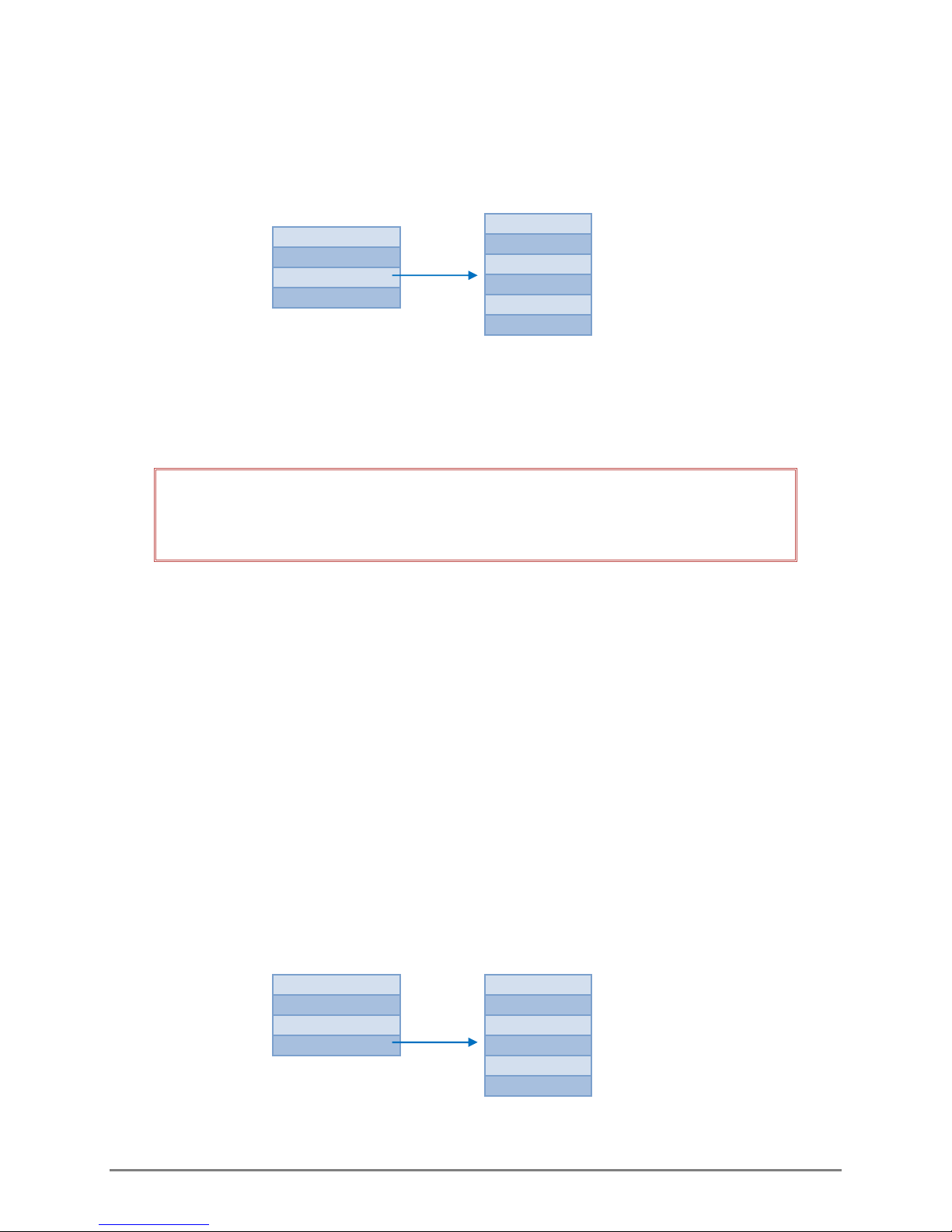
Slope – Displays the slope. Only appears if units are custom (cu). Insert the desired slope. Note that
the Stage units on the Status screen will be displayed as “cu” not in the unit of measurement
used in the slope calculation.
3.7 SETUP MENU
PURGE
SET STAGE
SETUP
DIAGNOSTICS
SITE
ADDRESS
RATE
TEMP F/C
AVG DUR
SDCARD
Figure 3-5: Setup sub-menu
Site: The site name can be input and is displayed here.
Address: This displays the Bubbler’s SDI-12 address. The Bubbler will be shipped with the default
address of zero. The address can also be set in this screen.
IMPORTANT! Changes made to the SDI-12 address with a data logger (using SDI-12
commands) will be reflected in the Bubbler. However, changes made to the Bubbler’s
address using the Bubbler’s Setup menu, will NOT be reflected in the data logger.
If the address is changed after the Bubbler has been configured with the data logger, you must ensure
the data logger configuration is also changed to recognize the new address. If this is not done, the
data logger will not be able to communicate with the Bubbler resulting in data loss.
Rate (Bubble Rate): Sets and displays the number of bubbles released per minute.
Temperature: Select the temperature units used to display the Bubbler’s internal temperature
readings (C or F).
AVGDUR (Averaging Duration): The period of time over which the samples taken will be used to
calculate the displayed stage value. It takes approximately 1 second to take a sample. The
average duration range is from 2-60 seconds.
SD Card: The SD card is used for service and factory logs and should only be accessed by trained FTS
personnel. If no SD card is inserted the SDCARD option screen will display a dash. If an SD card is
inserted the SDCARD option will display EJECT. This should always be selected prior to removing
the SD card.
3.8 DIAGNOSTICS
PURGE
SET STAGE
SETUP
DIAGNOSTICS
Figure 3-6: Diagnostics Sub-menu
BATTERY
TEMP
VERSION
UPDATE
DATE
TIME
700-Bubbler-Man Rev 2 14 Aug 2017 Page 13/35
Page 18
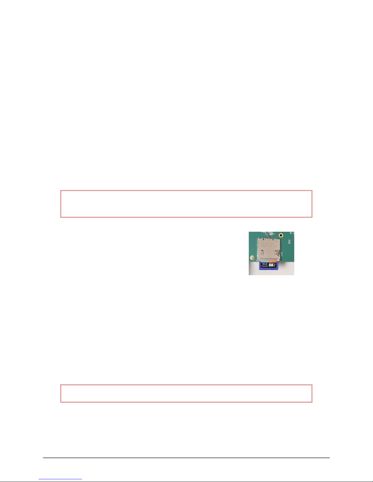
The diagnostics sub-menu is read only, with the exception of the Update function, and displays the
current state of the following items:
Battery: displays the current voltage
Temp: displays the internal temperature of the Bubbler
Version: displays the current firmware version
Update: used to update firmware
Date: displays the date (provided from the data collection platform)
Time: displays the time (provided from the data collection platform)
3.8.1 UPDATING FIRMWARE
If there is a firmware update required, a notice shall be posted to the FTS Support Website with
instructions on the firmware and how to download the update to a blank SD card. The only file on the
SD card should be the firmware file.
IMPORTANT! The Bubbler should be opened in a protected environment free from
moisture, dust and other airborne debris which may enter the enclosure.
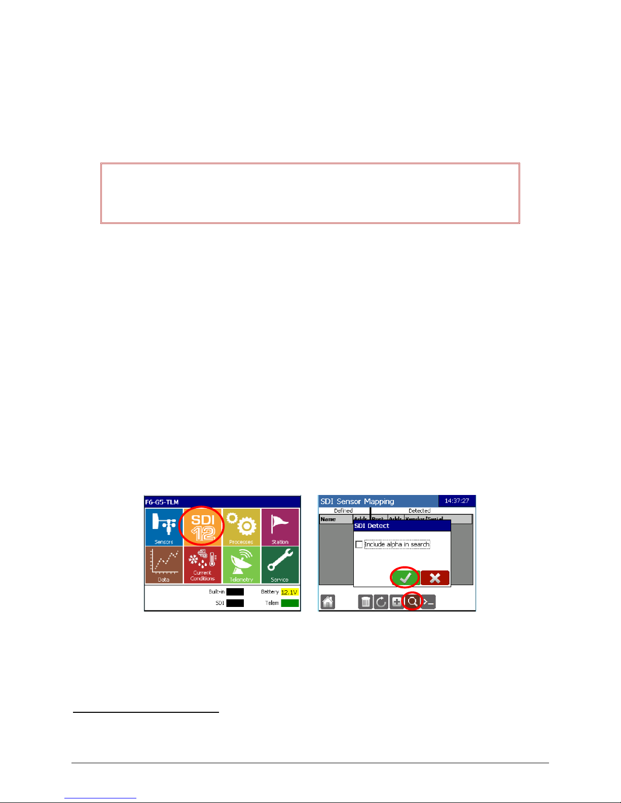
1) Open the Bubbler and insert the SD card in the SD slot
on the circuit board
Figure 3-7: SD card slot
2) Close the Bubbler and go to the Diagnostics sub-menu and select UPDATE. It will display the
firmware version.
It is good practice to compare the VERSION and UPDATE displays to ensure the update is to
a more current version.
3) Press the “Select/Accept” button to initiate the download. The process normally takes
approximately 45 seconds.
The display will flash while the update is downloading. When the display stops flashing, the
download is complete and the Bubbler will reset.
IMPORTANT! DO NOT power cycle the Bubbler until it has completed the download.
If the Bubbler is power cycled during the download process, it will revert to the previous firmware
version and the firmware update must be re-initiated.
700-Bubbler-Man Rev 2 14 Aug 2017 Page 14/35
Page 19
Chapter 4
CONFIGURATION USING AXIOM DATALOGGER INTERFACE5
The information in this chapter is specific to operating the Bubbler with an FTS Axiom Datalogger.
To operate the Bubbler with other data loggers, refer to their operator’s manuals. SDI-12 commands
for the Bubbler are found in Chapter 5.
IMPORTANT! Specific variables can be configured using the Bubbler’s user interface or
through the Axiom’s Bubbler sensor extension. The Bubbler and Datalogger will retain
the last input configuration regardless of which method is used.
The following variables can be set using either the Bubbler’s interface or through the data logger
Set stage
Stage units
Bubble rate
Temperature units
Averaging Duration
When used with an FTS Axiom Datalogger, the date and time will be set automatically.
Note that changes made on the Bubbler’s interface will not be reflected in the Datalogger’s screens
(and vice versa) until after the Datalogger has sent the SDI-12 command relating to the specific
variable. Once the command is sent, the Datalogger recognizes the latest change and will update its
configuration accordingly.
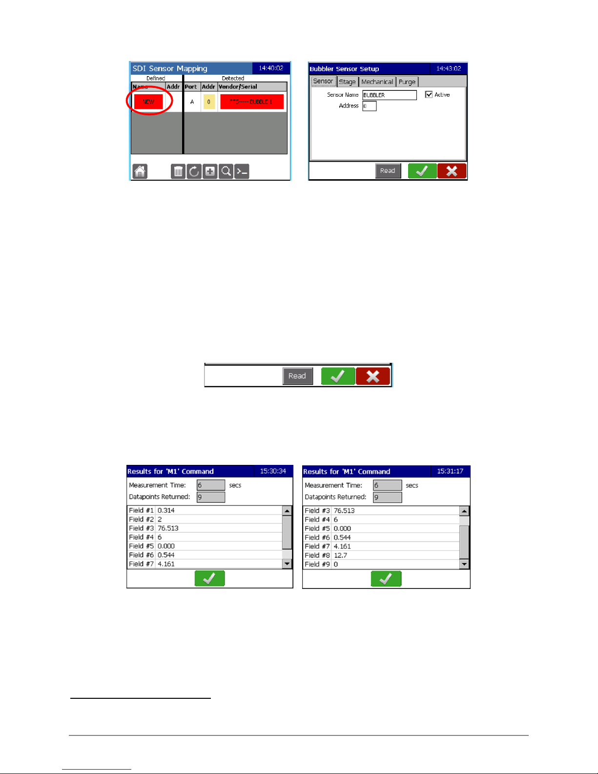
From the Datalogger’s Home screen, select the SDI-12 icon and then the Search icon. Select OK on the
SDI Detect screen. DO NOT check the “Include alpha in search” box.
The following screen will be displayed. Note that the Address displayed will be the address set in the
Bubbler. In this example it is the default address of zero (0). Tap on the “New” field to bring you to the
Bubbler Sensor Setup.
5
Refer to the Axiom Operator’s Manual (700-Axiom-Man) for complete configuration details and the Axiom
Telemetry Reference (700-Axiom-Telem) for detailed instructions on setting up messages.
700-Bubbler-Man Rev 2 14 Aug 2017 Page 15/35
Page 20
4.1 SETUP GENERAL INFORMATION
Each of the field names created in the Bubbler Sensor Setup tabs responds to a data point which will
be displayed on the Bubbler’s summary screen. Once a data point is created it will be available for
other functions such as Logging, Current Conditions, Processes, etc.
Default names: Most fields have default names which can be edited if desired by selecting the field
and then inputting the desired name using the pop-up keyboard.
In Edit mode, three icons are displayed on the bottom banner and are present in all tabs.
Read: This will send the M1 command6 and trigger a sensor reading. It will return the Measurement
Time, number of data points returned with the values taken.
OK (green checkmark): This accepts changes in ALL the tabs. Input all desired changes in all the tabs
prior to selecting OK. Once selected it saves the changes and then displays the Sensor screen.
Cancel (red X): This will cancel all the changes made in all the tabs. Tabs will revert to the previous
inputs.
6
Details of the M Commands can be found in Chapter 5.
700-Bubbler-Man Rev 2 14 Aug 2017 Page 16/35
Page 21
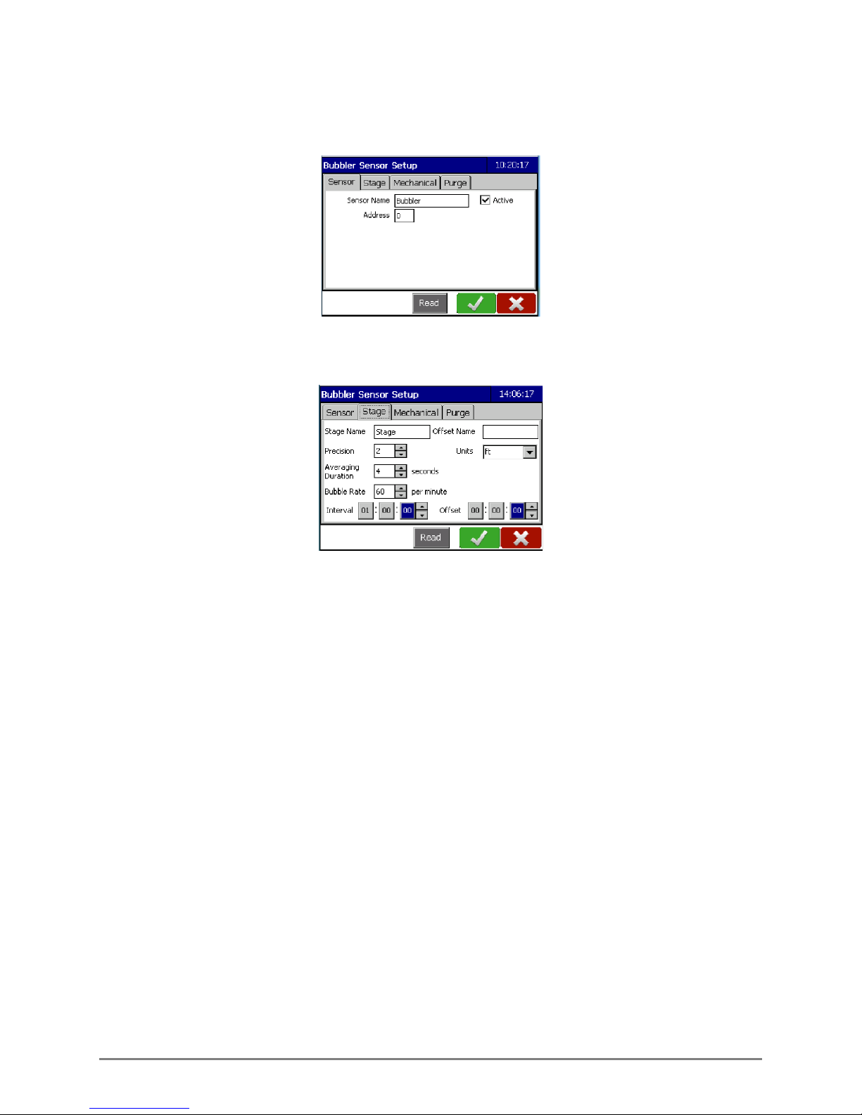
4.2 SENSOR TAB
Displays the default sensor name and Address of the Bubbler.
4.3 STAGE TAB
Stage Name: This is the name of the data point. Stage is the default name and can be changed if
desired.
Offset Name: Input the desired name for the Stage Offset data point. The offset is calculated
automatically by the Datalogger but will only be displayed on the main Bubbler Sensor screen if
the Offset Name field is populated. See section 4.6.
Precision: This indicates the number of decimal places to which the reading will be displayed. The
maximum number is three.
Units: Select the desired units of measurement using the drop down menu. The choices are
m (metres)
mm (millimetres)
cm (centimetres)
ft (feet)
in (inches)
cu (custom)
Setting Custom Unit (Slope)
Select Custom to input a slope. Once Custom is selected in the drop down menu, a blank field
will appear in which the desired slope can be input.
700-Bubbler-Man Rev 2 14 Aug 2017 Page 17/35
Page 22
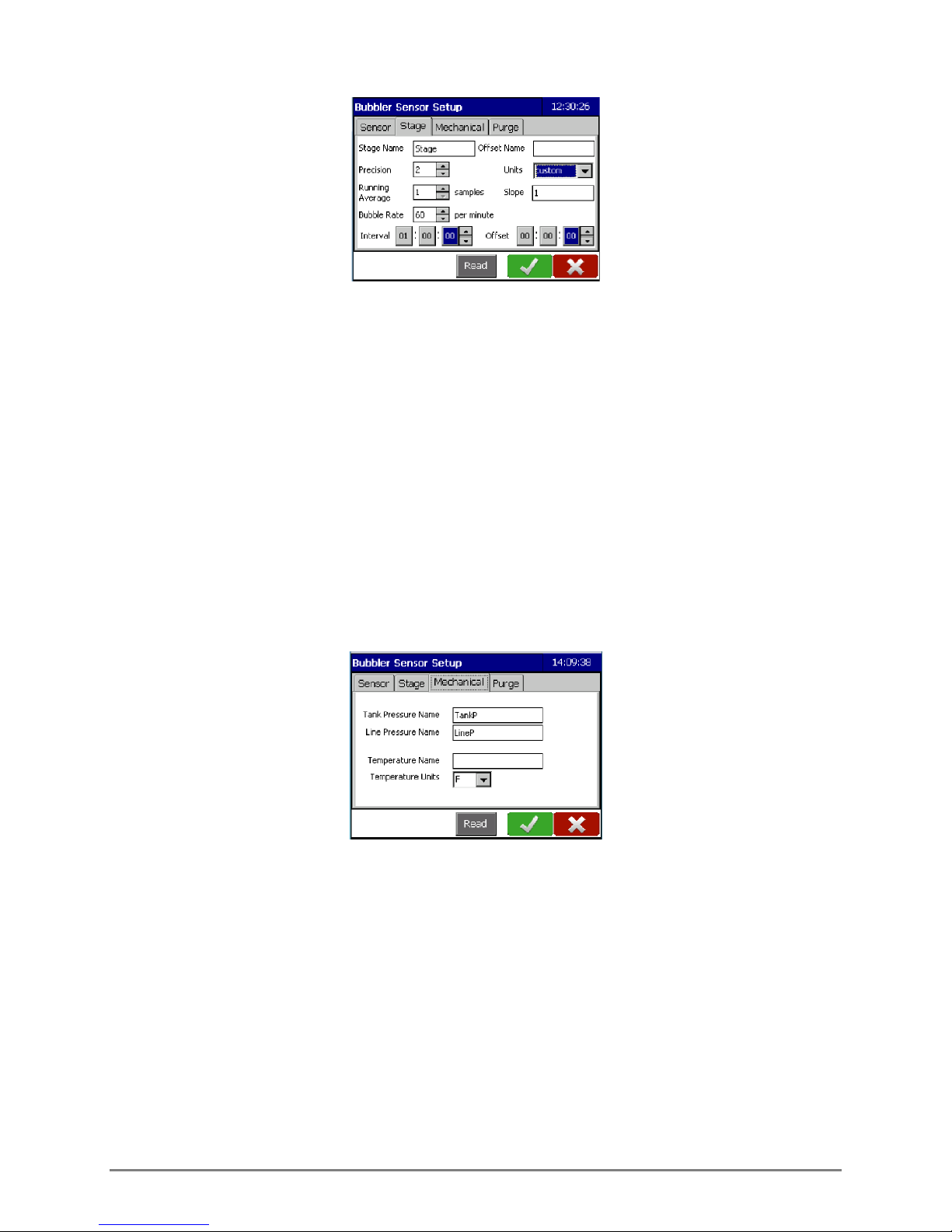
Averaging Duration: The period of time over which the samples taken. This will be used to calculate
the displayed stage value. It takes approximately 2 seconds to take a sample. The average
duration range is from 2-60 seconds.
Bubble Rate: This determines the number of bubbles per minute which will be released. The rate can
be set from 30-120 bubbles per minute.
Interval: This is how often a measurement will be taken. It is in HH:mm:ss format.
Offset: This determines the starting time the measurement will be taken based on time after
midnight.
For example: An interval of 01:00:00 and an offset of 00:15:00 means a measurement will be
taken every hour commencing at 15 minutes after midnight (00:15:00, 01:15:00, 02:15:00, etc.).
4.4 MECHANICAL TAB
Tank Pressure Name: The default name is TankP and can be changed if desired. Units are in PSI.
Line Pressure Name: The default name is LineP and can be changed if desired. Units are in PSI.
Temperature Name: Insert the desired name for the temperature variable.
Temperature Units: Select either C (Celsius) or F (Fahrenheit).
700-Bubbler-Man Rev 2 14 Aug 2017 Page 18/35
Page 23

4.5 PURGE TAB
Purges are conducted to clear the hose outlet of silt or debris which may be blocking it. The frequency
of the purges and the PSI used to conduct them are dependent on the environment and conditions of
the site. The Datalogger can initiate purges on a regular schedule, if the line pressure reaches a
threshold value, or under both circumstances. Purges will only take place if one or both of the options
are enabled.
Figure 4-1: Purge tab showing Scheduled and Threshold purge options selected
Scheduled Purge
For a scheduled purge, ensure the Enable Scheduled Purge checkbox is selected.
Select the desired pressure at which to conduct the purge. The pressure range is from 20-90 PSI. The
default value is 90 PSI.
Interval: The interval is how often the purge will occur and is in HH:mm:ss format. The minimum
purge interval is 10 minutes (00:10:00).
Offset: Optional. This determines the starting time the purge will commence based on time after
midnight.
For example: An interval of 24:00:00 and an offset of 10:15:00 means the purge will take place
daily (every 24 hours) at 10:15 a.m.
Purge if greater than
To conduct purges when the line pressure exceeds a threshold value, select the Purge if greater than
checkbox and input the desired threshold value.
700-Bubbler-Man Rev 2 14 Aug 2017 Page 19/35
Page 24
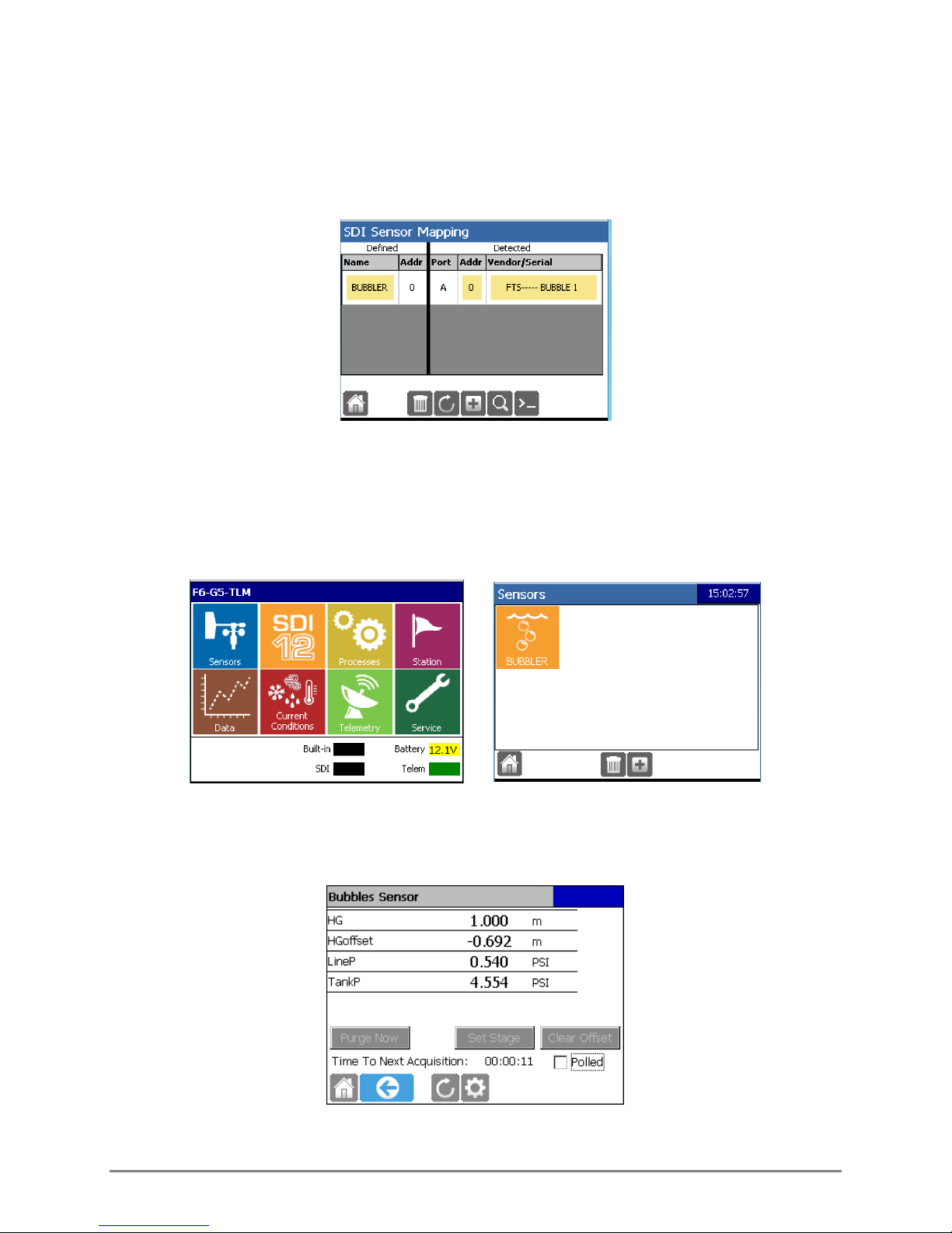
4.6 SAVE CONFIGURATION
Once all tabs have been completed, select the OK checkmark on any tab. The SDI Sensor Mapping
screen should display and indicate the sensor is mapped. View the Bubbler Sensor Screen and confirm
configuration (see section 4.7).
4.7 BUBBLER SENSOR SCREEN
From the home screen select the Sensors icon and then the Bubbler icon. Note that the name on the
icon will be the same as the Sensor Name input on the Sensor tab. This example retains the default
name.
All defined data points defined in the Bubbler Sensor Setup tabs will be displayed with the latest
measured values. Use the setup cog to display and edit the Bubbler Sensor Setup screen.
700-Bubbler-Man Rev 2 14 Aug 2017 Page 20/35
Page 25
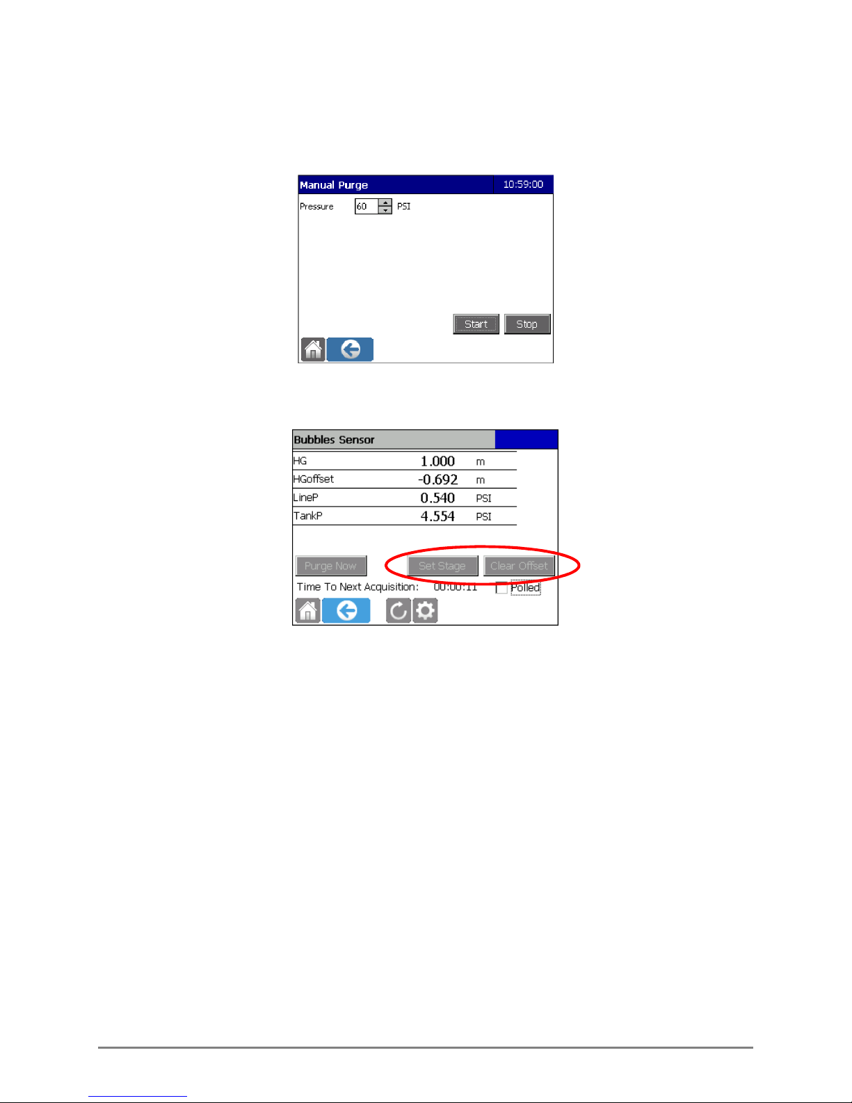
4.7.1 CONDUCT A MANUAL PURGE
Purge Now: Select this to conduct a purge. Input the desired pressure. The Purge PSI will remain at
this value until changed.
4.7.2 SET STAGE AND CALCULATE/CLEAR OFFSET
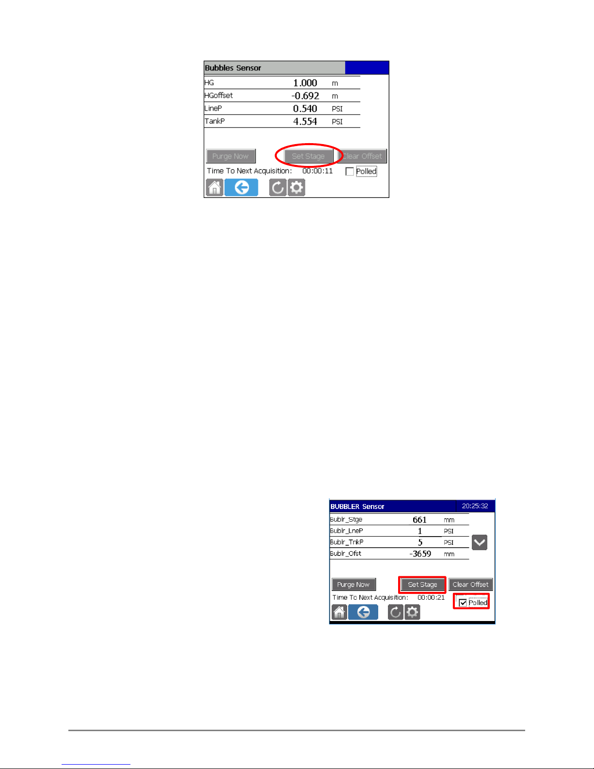
Set Stage and Clear Offset enable the user to set and clear the stage offset value. They are present
when a Stage variable is configured on the Stage tab. Once the stage is set, the Datalogger will
automatically calculate the Stage Offset. The Stage Offset will be displayed as a data point if the Offset
Name field was populated in the Stage Tab.
Set Stage
Once the sensor has been configured and is operating, the Set Stage and Clear Offset buttons can be
used. They are present only if a stage variable has been configured on the Stage tab.
There are two methods available for setting the stage offset in the Datalogger depending on if the
staff gauge reading is known or not. If it is known use the Set Stage button. If it is not known, use the
Polled feature.
Staff Gauge Reading Known
If the staff gauge reading is known, press Set Stage, enter the staff gauge value, and confirm the
changes.
700-Bubbler-Man Rev 2 14 Aug 2017 Page 21/35
Page 26
The Datalogger calculates the appropriate stage offset from the current stage sensor reading.
Polling
The polling option is meant as a temporary measure to confirm Bubbler operations and any data
collected during the polling will not be recorded by the Datalogger. It will also not affect the Bubbler
Setup values. That is to say, once polling is stopped, interval values will revert to those originally input
in the Bubbler Setup Screen.
The user can select the Polled checkbox and then press Set Stage to begin a series of Bubbler
readings while the user checks the staff gauge reading. After checking the staff gauge reading and
returning to the Datalogger, the user can select the appropriate time stamped Bubbler reading and
then enter the staff gauge value so that the Datalogger can calculate the appropriate stage offset.
The stage reported on the Display screen and on the Stage Offset Tool screen will use the units that
the user has selected during the setup process (If the FTS pressure transducer (SDI-PT) is being used
with the Axiom, the SDI-PT calculation (SDI-PT calc) will be applied if enabled during that sensor’s
setup).
The steps to set up polling follow:
1. Tap the Polled box, and then select Set
Stage.
700-Bubbler-Man Rev 2 14 Aug 2017 Page 22/35
Page 27
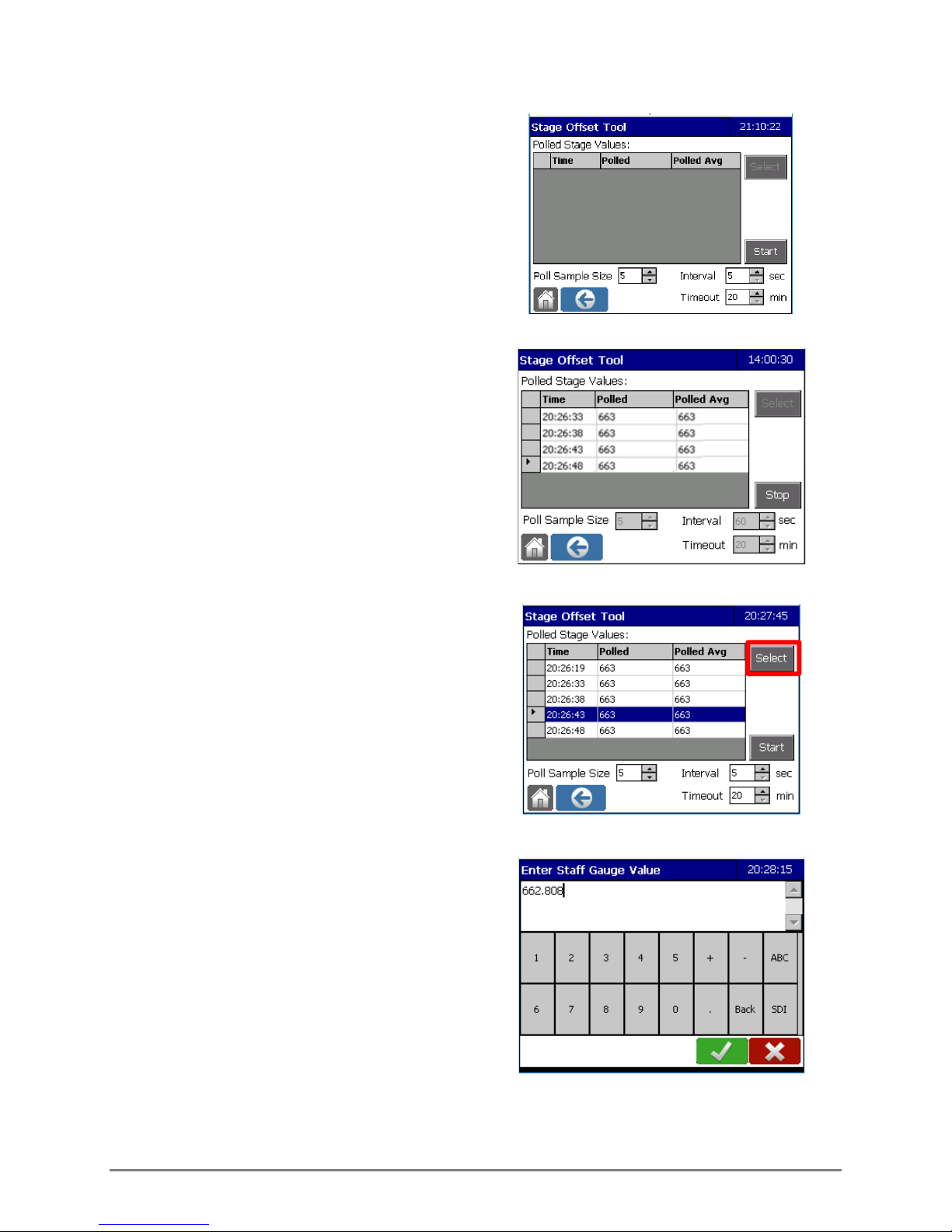
2. The Stage Offset Tool screen is displayed.
Enter the desired Interval and Timeout
times.
Interval is the polling interval and Timeout is
the period of time over which polling will take
place. The Poll Sample Size refers to how
many readings will be averaged per interval.
3. Synchronize your timepiece to the
Datalogger and select Start.
The screen is displayed in view only mode
and polling commences. Polling values will
be displayed until the Stop button is selected.
4. Go read the staff gauge. Note the time and
the Staff Gauge value.
5. When you return to the Datalogger select
STOP, scroll through the stage sensor
readings and tap on the time that
corresponds to your reading of the staff
gauge. Press Select.
6. The Enter Staff Gauge Value screen appears.
Enter the observed value and confirm.
700-Bubbler-Man Rev 2 14 Aug 2017 Page 23/35
Page 28
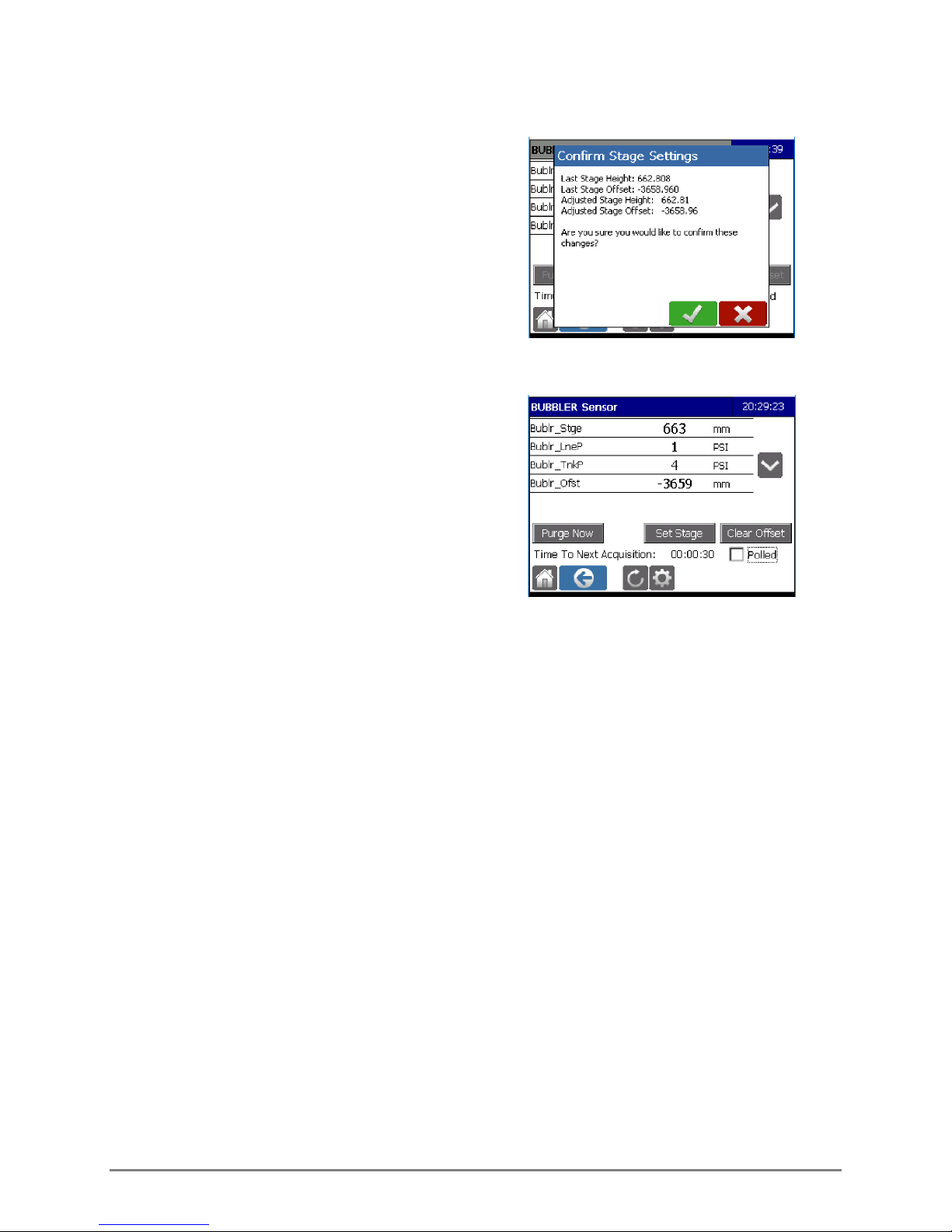
7. Confirm the new Stage Settings
8. The new Stage Offset will be calculated.
9. De-select the Polled box.
700-Bubbler-Man Rev 2 14 Aug 2017 Page 24/35
Page 29

aM!
aM1!
aM2!
Chapter 5
SDI-12 COMMANDS
5.1 STANDARD SDI-12 MEASUREMENT COMMANDS
The Bubbler uses the standard SDI -12 Commands and protocols7 which makes it compatible for use
with DCP’s or transmitters. The Bubbler’s specific measurement commands follow.
Note the following:
the “a” in each command should be replaced with the sensor address number
every command must terminate with an exclamation mark (!)
the CRC is added at the end of the message for commands with CRC
the measurement command must be followed by a Send Data command (aD0!) to view the
data
COMMAND(S) RESULTS
Measures:
aC!
aMC!
aCC!
aC1!
aMC1!
aCC1!
aC2!
aMC2!
aCC2!
*See Section 5.1.1 for measurement codes and meanings
Stage
Units of stage*
Health status/error indicator *
The health status bits will only be reset if the data logger performs an XCON
command or XDT for the SW_SYNC_TIME.
HW bits cannot be reset.
Measures:
Stage
Units of stage*
Temperature
Units of Temperature*
Offset (Units same as Stage)
Line Pressure (PSI)
Tank Pressure (PSI)
Battery Voltage (volts)
Health status/error indicator *
Measures:
Purge state*
Pump on time
Pump off count
Pump fault count
Health status/error indicator *
The format of the response to a Measurement command is atttn: in which:
a the sensor address
ttt the specified time, in seconds, until the sensor will have the measurement(s) ready
n the number of measurement values the sensor will make and return in one or more
7
In accordance with SDI-12 Specification, version1.3 http://www.sdi-12.org
700-Bubbler-Man Rev 2 14 Aug 2017 Page 25/35
subsequent D commands; n is a single digit integer with a valid range of 0 to 9
Page 30

Measurement response examples:
1) M Command followed by the Get Data Command:
0M!00043
: Bubbler at address 0, measurements will be ready in 4 seconds, and 3 fields will be returned.
0D0!+5.23+0+0
:data returned is stage (5.23), units of stage code (feet) and health status code (0).
2) M1 Command followed by the Get Data Command:
0M1!00049
: Bubbler at address 0, measurements will be ready in 4 seconds, and 9 fields will be returned.
0D0! +5.23+0+23.5+7-1.3+20+30+12.5+1
: data returned is stage (5.23), units of stage(feet), temperature (23.5), units of temperature (F),
offset (-1.3), line pressure (20), tank pressure (30), battery voltage (12.5), health status code (1).
5.1.1 SDI -12 MEASUREMENT COMMAND CODES
The following numerical codes will be returned for units of stage, temperature, purge codes and
health status.
UNITS OF STAGE PURGE CODES
Code Measurement Unit Code Meaning
0
Feet (ft)
1
Inches (in)
2
Metres (m)
3
Centimetres (cm)
4
Millimetres (mm)
5
Custom slope
0
Purge enabled
1
Purging
2
Purge disabled
HEALTH STATUS INDICATORS
Value Meaning
0 No error detected
1 DL & Bubbler out of sync
2 Has rebooted
4 Needs date & time set
ERROR INDICATORS
Value Meaning
256 Battery out of range
512 Temperature out of range
1024 Compressor fault
2048 Line blocked
4096 Line pressure high
8192 Tank leak
If the bubbler is operating normally, the health
status/error field will be populated with a zero. If there
is a single indicator, the health status/error field will
return one of the values seen in the table to the left.
A value other than one which appears in the table
means more than one status/error indicator was
detected.
Refer to the troubleshooting guide (Appendix B) for
details on rectifying status/error indicators and
determining the specific indicators when multiple
indicators are detected.
Code Measurement Unit
TEMPERATURE
6 7 Degrees Fahrenheit (F)
Degrees Celsius (C)
700-Bubbler-Man Rev 2 14 Aug 2017 Page 26/35
Page 31
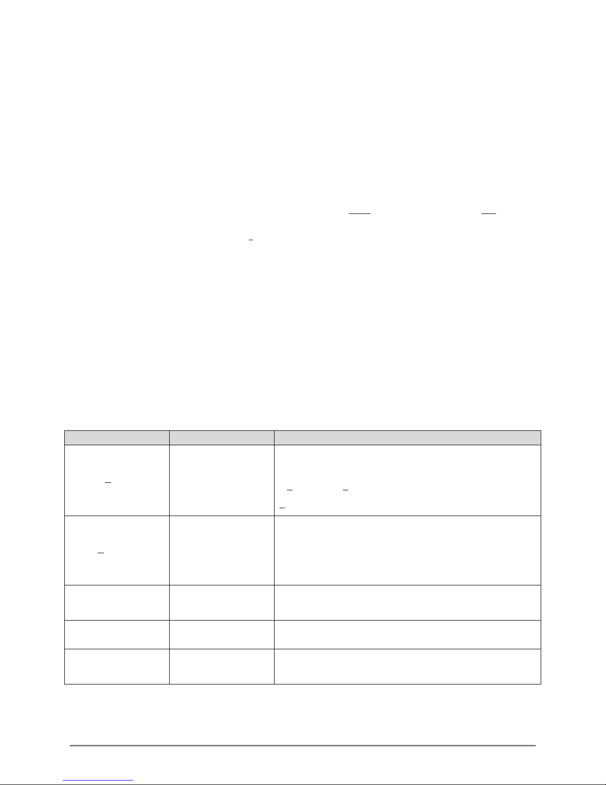
5.2 EXTENDED (X) COMMANDS
In addition to the standard set of commands, the FTS Bubbler has an extension of custom SDI -12
commands called X commands that access specific features of the sensor.
The format of X commands follows the requirement for standard SDI-12 commands in that the first
character of every command must be a sensor address which is then followed by the X command and
terminated by an exclamation mark. Likewise, the first character of a response is also the address
character.
Some commands can be used to either view a parameter (“get”) or input a parameter (“set”). Set
commands use an optional parameter P or a float parameter P.p. To “set” a value, the P or P.p should
be replaced with the desired numeral(s). If the optional parameter is not used, it is a “get” command
and will return the previously set value. .
5.2.1 Required Formatting Elements
In order for X commands to be valid, the following format conditions must be met:
the X must be capitalized; character case is not important for any other element
there must be no spaces within the command
in “set” commands, the ’P or P.p’ or should be replaced with the desired numerals.
5.2.2 X Commands List
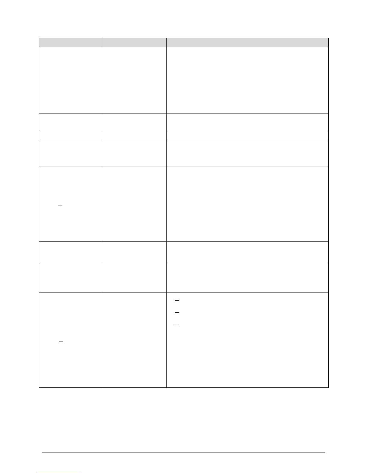
X Command Definition Comments
Bubbler needs to be power-cycled after this
command in order to return to normal operations.
If P is empty or P=B is begin bleed
P=E is end bleed.
aXBLDP!
Begin/end tank
bleed
Set or get number of bubbles per minute, if P is
empty then return setting.
Minimum value is 30 and max value is 120, default
aXBRP!
Get/set bubble
rate
is 60.
aXCON!
aXDOC!
aXDOM!
Configuration
change
Get date of
calibration
Get date of
manufacture
Reset the configuration change flag indicating the
settings are in sync with the data logger.
Returns in YYYYMMDD format.
Returns in YYYYMMDD format.
700-Bubbler-Man Rev 2 14 Aug 2017 Page 27/35
Page 32
X Command Definition Comments
aXDTYYYYMMDD, HHMMSS!
Example: a20170125,130000! Will set the Bubbler’s
aXDTYYYYMMDD
, HHMMSS!
Set date and time
date to 2017 January 25 1 p.m.
Date range is from
Jan 1 22105)
Time range is from 000000 to 235959
20170101 – 21050101 (
Jan 1 2017 to
aXDT! Get date and time
Returns date and time in YYYYMMDD, HHMMSS
format.
aXFSN! Get serial number Example: 123456
Get firmware
aXI!
version and build
Example: 1.0.65,2017-06-21 17:19:29 UTC
date
Site ID is an alphanumeric string of maximum 10
characters
aXID!abubbler1 (gets Site ID of Bubbler1)
aXIDP! Get/set site id
aXIDbubbler1! (sets Site ID to bubbler 1)
There is no error checking for symbols. If the user
wants to enter symbols he can. But symbols are not
supported from the display.
aXPCB!
Get hardware
revision
This is derived by a resistor set in the hardware.
Get pump
aXPUMP!
(compressor)
Returns on-time, on-off count, and fault count.
statistics
aXPRP!
700-Bubbler-Man Rev 2 14 Aug 2017 Page 28/35
Begin/end purge
or set pressure
If P is ‘B’ = begin purge mode
If P is ‘E’ = end purge mode.
If P is a number then set purge pressure.
Example: aXPR90! (set purge pressure at 90 psi)
Valid range is 20 to 90.
Default :90
If no parameter (P) is input, the purge will be
conducted with the previous setting.
Page 33
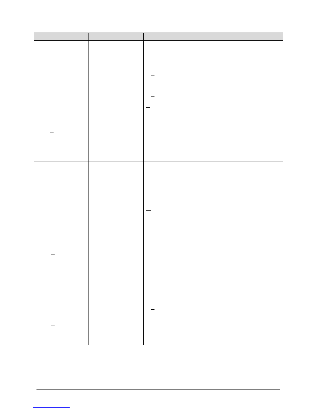
X Command Definition Comments
You can check the stage value by issuing an M
command.
aXSHP!
Get/set stage
height value
aXSLP! Get/set slope
Get/set period for
aXSPP!
samples in
seconds
If P=nnn.n stage value is set to the input number
If P=Z the stage offset is zeroed
aXSH10!a
If P is empty then return value in current units.
P = nnn.nnnn
aXSL 2.786!a
aXSL!a 2.786
The value range is from 0.100 to 999.999 (inclusive).
Once the slope is set, the units are considered
“custom”.
P = nn
aXSP30!
The min value is 4 and max value is 60 seconds.
Default : 4
P = 0 sets units to ft (feet)
aXSUP! Get/set stage units
aXTUP!
Get/set
temperature units
= 1 sets units to in (inches)
= 2 sets units to m (meters)
= 3 sets units to cm (centimeters)
= 4 sets units to mm (millimeters)
= 5 sets units to Custom Units – this is
automatically set when the slope is changed
manually using the ‘aXSLs’ command
You cannot use XSU to set the value to ‘5’ (you
must use XSL)
If P = 6 temperature is Fahrenheit
If P = 7 temperature is Celsius
aXTU6!a
aXTU!a6
700-Bubbler-Man Rev 2 14 Aug 2017 Page 29/35
Page 34
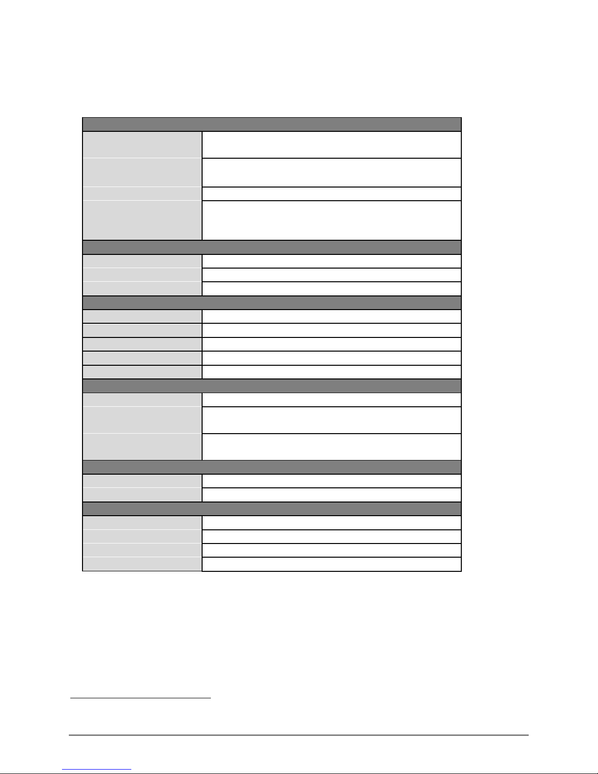
Appendix A SPECIFICATIONS
PERFORMANCE DATA
Accuracy 3mm (0.01ft) or 0.1% of the effective stage, whichever
is greater
Operating Pressure
(Depth)
Purge Pressure 20 to 90 PSI (user selectable)
Gas Delivery Constant flow bubbler with user programmable bubble
AMBIENT CONDITIONS
Operating Temperature -40°C to +60°C (-40°F to +140°F)
Storage Temperature -60°C to +80°C (-76°F to +176°F)
Relative Humidity 0-95% non-condensing
PHYSICAL
Dimensions 254mm x 203mm x 152 mm (10” x 8” x 6”)
Weight 5.88 kg (13 lbs)
Ingress Protection IP66
Enclosure Material NEMA 4X Fiberglass
On-Board Screen 4x20 character display
MECHANICAL
Compressor Capacity Up to 28.3 L/min
Orifice Line Fitting Brass Swagelok tube fitting
Connection to
Desiccator
POWER
Power Requirements 9.6 to 12VDC
Average Active Current 22 mA
SDI INTERFACE
Version 1.3
Protocol 7 bit even parity, 1 stop bit
Bit Rate 1200 BPS
Supply Voltage 10.6 – 16 VDC
0 to 30 PSI
(0 to 21m) (0 to 70ft)8
rate.
30 to 120 bubbles per minute
(for 3/8” outside diameter hose)
Barbed hose fitting for 5/16” ID hose
8
Based on USGS conversion factor of 2.3073 ft of pure water @50C per PSI
700-Bubbler-Man Rev 2 14 Aug 2017 Page 30/35
Page 35

Appendix B TROUBLESHOOTING GUIDE
B.1 MECHANICAL INDICATORS
PROBLEM POSSIBLE CAUSE ACTIONS
Pressure
dropping/excessive
pump operation
Pump not running Insufficient power 1) Ensure Bubbler has a direct power source. It
Incorrect Stage A) Erroneous offset value
System leak (either internal or
at bubbler line connections)
Ensure orifice line is correctly seated and
tightly attached at all connection points
cannot be fully powered through the
Datalogger’s SDI port (section 2.6.2).
2) Check power connections (including solar
panel, if using)
3) Check battery (replace if necessary)
1) Set Stage directly by entering the staff
gauge value (if known); or
2) Poll the sensor
Refer to Section 4.6.2
B) Blocked orifice line
1) Conduct a purge
2) Ensure orifice is free from larger
obstructions/blockages
B.2 BUBBLER STATUS SCREEN FAULT INDICATORS
FAULT POSSIBLE CAUSE ACTIONS
BATTERY
COMPRESSOR Cannot clear blocked line 1) Inspect along length of line for crimps,
Insufficient power
1) Ensure Bubbler has a direct power
source. It cannot be fully powered
through the Datalogger’s SDI port
(section 2.6.2).
2) Check power connections
3) Check battery (replace if necessary)
compressed areas.
2) Inspect line output for blockages
3) May have to bleed tank, cut power and
remove/replace line
700-Bubbler-Man Rev 2 14 Aug 2017 Page 31/35
Page 36
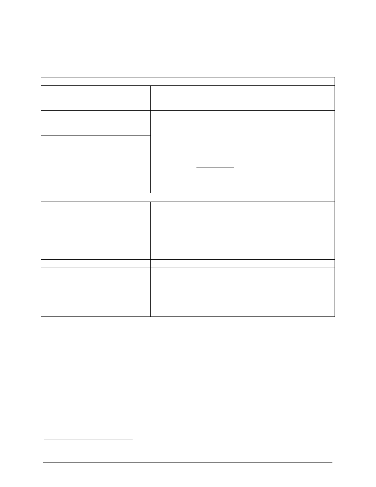
B.3 HEALTH STATUS/ERROR INDICATORS
A value other than one which appears in the Health Status/Error table means more than one status
flag was detected. In order to determine the indicated status flag, use the f process in section B.3.2.
HEALTH STATUS INDICATORS
VALUE MEANING ACTION
0
1
Bubbler operating
normally
Data logger & Bubbler out
of sync
2 Has rebooted
3
Health status 1 and 2
triggered
4 Needs date & time set
7
Health status 1, 2 and 4
triggered
ERROR INDICATORS
VALUE MEANING ACTION
256 Battery out of range
512 Temperature out of range
1024 Compressor fault Contact FTS Support and return Bubbler to FTS for repairs
2048 Line blocked 1) Conduct a purge
4096 Line pressure high
8192 Tank leak Contact FTS Support and return Bubbler to FTS for repairs
None required
Synchronize the Axiom Datalogger and Bubbler and reset the
configuration change flag.
Issue the aXCON! command (see section 5.2 for details)
Set the date and time.
Issue the aXDTYYYYMMDD, HHMMSS! command
(see section 5.2 for details)
Take action as indicated for 1, 2 and 4.
1) Ensure Bubbler has a direct power source. It cannot be fully
powered through the Datalogger’s SDI port (section 2.6.2).
2) Check power connections (including solar panel if using)
3) Check battery (replace if necessary)
Take measures to protect Bubbler from extreme ambient
temperature conditions.
2) Ensure orifice is free from larger obstructions/blockages
3) Inspect along length of line for crimps, compressed areas.
4) May have to bleed tank, cut power and remove/replace line
B.3.1 MANAGING HEALTH STATUS INDICATORS
If using an Axiom Datalogger, health status indicators of 1, 2 and 4 (and by default 3 and 7) are
managed by the Datalogger. When one of the aforementioned indicators is detected, the Axiom
Datalogger will automatically send the required X-command to rectify the situation. If your Axiom is
continuously showing a health status indicator of 7, that indicates a failure of the Datalogger to fully
communicate with the Bubbler and a site visit is required to determine the cause.
If using a non-AXIOM data logger the most common health status indicator will be 4. A “4” means the
Bubbler is still operating normally, but the bubbler’s SD card9’s time stamp will not be accurate. If your
data logger can be programmed to set the Bubbler’s date and time every 24 hours (as the Axiom
does), the appearance of this indicator can be mitigated.
9
The SD card is used by FTS factory personnel for troubleshooting.
700-Bubbler-Man Rev 2 14 Aug 2017 Page 32/35
Page 37

Also, for non-AXIOM data loggers, if any configuration change was made or the Bubbler was rebooted
(after a power cycle, for example), the aXCON! command should be issued to clear those health status
indicators.
B.3.2 DETERMINING MULTIPLE HEALTH STATUS INDICATORS
1) Value (a) is returned from the get data (aD!) command in the health status field. Find the value
(b) in the Health Status Table that is closest to but less than (a). Value (b) indicates the first health
status indicator.
2) Subtract (b) from (a): a-b= c
3) Find the value (d) in the Health Status Table that is closest to but less than (c). Value (d) indicates
the second health status indicator.
4) Subtract (d) from (c): c-d = (e)
5) Find the value (f) in the Health Status Table that is closest to but less than (e). Value (f) indicates the
third health status indicator.
6) Continue in this fashion until the difference of the two values = 0
Example: 0D0! +5.23+0+23.5+7-1.3+20+30+12.5+263
1) Value (a) = 263. Value (b) = 256 = Battery out of range error
2) 263-256 = 7. Health status value closest to 7is 4= Needs time and time set
3) 7 – 4 = 3 Health status value closest to 3 is 2 = the Bubbler has rebooted
4) 3-2 = 1 Health status Value closest to 1 is 1 = data logger and Bubbler are out of
Synchronization
5) 1-1 = 0 No further indicators
700-Bubbler-Man Rev 2 14 Aug 2017 Page 33/35
Page 38
Appendix C PARTS AND ORDERING INFORMATION
FTS Bubbler ordering information
Part Number Description
SDI-Bubbler Bubbler, SDI
Spare Parts / Accessories Ordering Information
Part Number Description
19861 Power Connector Assembly, Bubbler
19862 Data Connector Assembly, Bubbler
19865 Swagelok Nut Set, Bubbler
19443 1.5m SDI communication cable with flying leads both ends
19442 1.5m SDI communication cable, MC one end and flying leads other
end
18945 8ft cable with fuse, flying leads on both ends
19062 Orifice Tubing, .125" ID x .375" OD - 500ft Roll
19063 USGS Standard Orifice Fitting, Galvanized
18742 Hose Clamp, Worm Drive, 2.5 to 5.5
19055 Desiccant Air Dryer - large
19056 Replacement desiccant - large
19060 Desiccant Air Dryer – small
19057 Replacement desiccant - small
19468 Desiccant tubing – 1ft sections
19469 Barbed hose fitting for 5/16” ID hose
DESICCANT-BRKT-LRG Desiccant bracket and screws - large
DESICCANT-BRKT-SM Desiccant bracket and screws - small
700-Bubbler-Man Rev 2 14 Aug 2017 Page 34/35
Page 39

DOCUMENT REVISION HISTORY
Revision # Date Description
1 1 Aug 2017
SDI-12 commands based on ver 0.78 of the Bubbler SDI
Command Set
2 14 Aug 2017 Updated for Axiom AS ver 3.8.0.57 (Bubbler extension)
700-Bubbler-Man Rev 2 14 Aug 2017 Page 35/35
 Loading...