


OPERATION AND PARTS MANUAL
DRUM PUMP MOTORS
Models: M3 M5 M3T M3X M5T M5X M6 M6X M7T M7X M10X M15-M40 M58P M59P

EU Declaration of Conformity
Finish Thompson Inc. hereby declares that the following electrical equipment fully complies
with the applicable health and safety requirements as specified by the EU directives listed.
The product may not be taken into service until it has been established that the driven
Drum and Container Pump complies with the provisions of all relevant EU Directives
provided pumps manufactured by Finish Thompson are used.
This declaration is valid provided that the devices are fully assembled and no modifications
are made to these devices.
Type of Device:
Electric Motors for Driving Drum
and Container Pumps
Models:
M3V-UK M5 M5T M5V M5X M10X
M13 M59P M59H S2 S3
EU Directives (and their applicable amendments):
Low Voltage (2014/35/EU)
Electromagnetic Compatibility (2014/30/EU)
Specific standards applied:
EN 60335-1 EN60335-2-41
EN 55014-1 EN 55014-2
EN 60529
Signed,
_________________________________
Casey D. Bowes
CEO and President
20 April 2016
Person(s) Authorized to Compile Technical File: Finish Thompson GmbH
Otto-Hahn-Strasse 16
Maintal, D-63477 DEU
Telephone: 49 (0)6181-90878-0
2

EU DECLARATION OF CONFORMITY
Finish Thompson Inc. hereby declares that the following machines fully comply with the applicable
health and safety requirements as specied by the EU Directives listed. This declaration is valid
provided that the devices are fully assembled and no modications are made to these machines.
Type of Device:
Pump Motor
Pump Motor Models:
M10X
EU Directives:
Equipment and protective systems intended for use in potentially
explosive atmospheres (2014/34/EU)
EC-Type Examination:
Physical Technical Testing Institute 1026
Ostrava-Radvanice
FTZU 08 ATEX 0083X
Product Quality Assurance Notication:
Physical Technical Testing Institute 1026
Ostrava-Radanice
FTZU 08 ATEX Q 003
Applicable Harmonized Standards:
EN 60079-0:2012
EN 60079-1:2014
Signed,
Casey D. Bowes
CEO and President
April 20, 2016
3

EU Declaration of Conformity
Finish Thompson Inc. hereby declares that the following machine(s) fully comply with the
applicable health and safety requirements as specified be the EC Directives listed. The
product may not be taken into service until it has been established that the driven Drum
and Container pump complies with the provisions of all relevant EC Directives. The
complete product complies with the provisions of the EC Directive on machinery safety
provided
pumps manufactured by Finish Thompson Inc. are used.
This declaration is valid provided that the devices are fully assembled and no
modifications are made to these devices.
Type of
Device:
Air Motors for Driving
Drum
and Container
Pumps
Models:
M6 M6X M18 M19 M20 M57
M65 M66 S4
EC
Directives:
Machinery Safety
(2006/42/EC)
Applied Harmonized
Standards:
EN ISO 12100 Part
1
EN ISO 12100 Part
2
EN
983
Manufacturer:
Finish
Thompson
Inc.
921 Greengarden
Road
Erie, Pennsylvania 16501-1591
U.S.A
Signed,
_
President
27 February 2015
Person(s) Authorized to Compile Technical File: Finish Thompson GmbH
Otto-Hahn-Strasse 16
Maintal, D-63477 DEU
Telephone: 49 (0)6181-90878-0
4

TABLE OF CONTENTS
TABLA DE CONTENIDO
Introduction ........................................................ 6
Warranty and Return Policy ............................... 6
Safety Precautions .............................................. 7
Maintenance Precautions ................................... 7
Installation .......................................................... 8
M3 & M5 Models .............................................. 9
Assembly Drawing and Parts List
M3T & M5T Models ........................................ 10
Assembly Drawing and Parts List
M7T Models ......................................................11
Assembly Drawing and Parts List
M6 Model......................................................... 12
Assembly Drawing and Parts List
M6X Model ...................................................... 13
Assembly Drawing and Parts List
M3X, M5X, M7X & M10X Models ................ 14
Introducción ....................................................... 6
Garantía y Póliza de Devolución ....................... 6
Precauciones de Seguridad ................................ 7
Precauciones de Mantenimiento ........................ 7
Instalación .......................................................... 8
Modelos M3& M5 ............................................. 9
Dibujo de Armadura y Lista de Partes
Modelos M3T & M5T ...................................... 10
Dibujo de Armadura y Lista de Partes
Modelos M7T ....................................................11
Dibujo de Armadura y Lista de Partes
Modelo M6....................................................... 12
Dibujo de Armadura y Lista de Partes
Modelo M6X .................................................... 13
Dibujo de Armadura y Lista de Partes
Modelos M3X, M5X, M7X & M10X .............. 14
BT Models ....................................................... 14
Assembly Drawing and Parts List
M58P-M59P Models ........................................ 15
Assembly Drawing and Parts List
Static Protection Kit ......................................... 16
Modelo BT ....................................................... 14
Dibujo de Armadura y Lista de Partes
Modelos M58P, M59P ...................................... 15
Dibujo de Armadura y Lista de Partes
Guias para el Equipo de Protección Estático ... 17
5

INTRODUCTION
INTRODUCCIÓN
FTI has been an international designer and manufacturer of drum
pumps and mixers for over twenty years. We make drum pump
selection easy with our complete line of interchangeable motors
and tubes. When properly installed and operated, your Finish
Thompson drum pump or mixer will provide long, trouble free
service.
FTI ha sido diseñador y fabricante internacional de bombas de
tambor y mezcladoras por más de veinte años. Hacemos selección
de bombas de tambor fácil con nuestra línea completa de motores
y tubos intercambiables. Cuando se instala y se maneja correctamente, su bomba de tambor o mezcladora Finish Thompson le
dará servicio por un largo tiempo y sin problemas.
WARRANTY GARANTÍA
Finish Thompson, Inc (manufacturer) warrants this product to
be free of defects in materials and workmanship for a period of
one year from date of purchase by original purchaser. If a warranted defect, which is determined by manufacturer’s inspection,
occurs within this period, it will be repaired or replaced at the
manufacturer’s option, provided (1) the product is submitted with
proof of purchase date and (2) transportation charges are prepaid
to the manufacturer. Liability under this warranty is expressly
limited to repairing or replacing the product or parts thereof and
is in lieu of any other warranties, either expressed or implied.
This warranty does apply only to normal wear of the product or
components. This warranty does not apply to products or parts
broken due to, in whole or in part, accident, overload, abuse,
chemical attack, tampering, or alteration. The manufacturer accepts no responsibility for product damage or personal injuries
sustained when the product is modied in any way. If this warranty
does not apply, the purchaser shall bear all cost for labor, material
and transportation.
Manufacturer shall not be liable for incidental or consequential
damages including, but not limited to process down time, transportation costs, costs associated with replacement or substitution
products, labor costs, product installation or removal costs, or loss
of prot. In any and all events, manufacturer’s liability shall not
exceed the purchase price of the product and/or accessories.
Finish Thompson, Inc (el fabricante) garantiza este producto contra
todo defecto de materiales y mano de obra durante un periodo de un
año des de la fecha de adquisición por parte del comprador original.
Si, dentro de este periodo, se detecta algún defecto cubierto por la
garantía mediante una inspección del fabricante, éste se encargará de
corregirlo, mediante reparación o sustitución, a su elección, siempre
y cuando: (1) el producto le sea devuelto con algún comprobante de
la fecha de compra y (2) a portes pagados. La responsabilidad de
esta garantía se limita expresamente a la reparación o sustitución
del producto o de partes del mismo, y sustituye a cualquier otra
garantía expresa o implícita. Esta garantía sólo se aplica al desgaste
del producto o de sus componentes derivado del uso normal. No es
aplicable a productos o piezas cuya rotura se deba, en todo o en parte,
a accidentes, sobrecargas, abusos, agresión química, manipulación
o alteración. El fabricante declina toda responsabilidad por daños
en el producto o lesiones personales que se produzcan después de
modicar el producto en cualquier forma. Si el comprador no hace
valer esta garantía, deberá asumir todos los gastos de mano de obra,
material y transporte.
El fabricante no es responsable de los daños consecutivos o resultantes incluidos, aunque sin limitación, los relacionados con
la parada de procesos, costes de transporte, costes asociados a la
sustitución de productos, costes de mano de obra, costes de retirada
o instalación de productos, o perdida de benecios. En cualquier
caso, la responsabilidad del fabricante no sobrepasará el precio
de compra del producto y/o los accesorios.
RETURN POLICY
Should you have any problems with this product, please contact
the distributor in your area. The distributor will then determine
if a return to the factory is necessary and will contact the factory
for a return authorization number.
Call our toll free Technical Service Hot Line, 1-800-888-3743,
if you have any questions regarding product operation or
repair.
PÓLIZA DE DEVOLUCIÓN
Si usted tiene cualquier problema con este producto, por favor
póngase en contacto con el distribuidor en su area. Entonces el
determinará si una devolución a la fábrica es necesaria y se pondrá
en contacto con la fábrica para obtener un número de autorización
de devolución.
Llame nuestro servicio técnico al numero 814-455-4478 si tiene
pregunts de operación o reparación.
6

SAFETY
PRECAUCIONES DE
PRECAUTIONS
ALWAYS wear protective clothing, eye protection and follow
standard safety procedures when handling corrosive or personally
harmful materials.
NEVER use a plastic pump or an open, splashproof or TEFC motor
when pumping or mixing ammable or combustible material.
ALWAYS use and store in an upright position.
NEVER immerse motor in liquid.
ALWAYS place motor in the OFF position prior to connecting the
power source.
ALWAYS check motor label plate for the correct power supply
requirements.
ALWAYS have manufacturer, its service agent or similarly qualied
persons replace supply cord if damaged in order to avoid a hazard.
ALWAYS use an approved plug for Class I, Division 1, Group C
& D applications on the X Series motors.
Noise level at a distance of 3 feet:
S Series - M3, M5 73 db (Splash proof)
T Series - M3T, M5T 77 db (Totally enclosed
fan cooled)
A Series - M6 at 80 psi line pressure 90 db (Air)
M58P & M59P 85 db (800 watt)
SEGURIDAD
SIEMPRE use ropa protectiva, protección para los ojos y siga
procedimentos de seguridad básicos cuando maneje materiales
corrosivos.
NUNCA use una bomba de plástico en los motores abiertos, contra
salpiqueos o TEFC cuando se bombéa o se mezcla materiales
combustibles o inamables.
SIEMPRE use y almacene recto.
NUNCA sumerga el motor en líquido.
SIEMPRE ponga el motor en la posición OFF antes de conectar
la corriente electrica.
SIEMPRE revise la placa por los requerimientos correctos de
corriente electrica.
SIEMPRE use un enchufe aprovado para la Clase I, la Division 1,
las aplicaciones de los Grupos C & D en el motor de la Serie X.
Nível de ruido a una distancia de 3 pies:
Serie S - M3, M5 73 db (Contra alpiqueos)
Serie T - M3T, M5T 77 db (TEFC -Totalmente
sellada con ventilación)
A Series M6 at 80 psi línea
de presión 90 db (Aire)
M58P y M59P 85 db (800 watt)
MAINTENANCE
PRECAUTIONS
ALWAYS store motor upright and away from corrosive liquids
and vapors.
ALWAYS use an automatic air line lubricator, moisture trap
and lter in the airline ahead of an air motor. (Use detergent
SAE #10 in lubricator). Do not exceed 80 psi (551 kPa) on
M6 and 100 psi (689 kPa) on all other air motors.
Motor Models M3, M3T, M5, M5T, M58P and M59P are
10,000 rpm. Motor brushes in these models should be replaced every 200-300 operating hours to assure trouble free
service.
Motor Models M3, M3T, M5, M5T, M7T, M8T, M58P
andM59P contain a circuit breaker (overload). If motor will
not operate, check the circuit breaker.
Motor Models M3X and M5X have a 400-600 operating hour
brush life. Model M10X has a 200-300 operating hour brush
life. M3X, M5X and M10X motor brushes require factory
replacement.
PRECAUCIONES DE
MANTENIMIENTO
SIEMPRE guarde el motor en una posición vertical lejos de
líquidos o vapores corrosivos.
SIEMPRE use un lubricador automático con trampa de hu-
medad y ltro en la línea de aire antes del motor. (Use el
detergente SAE número 10 en el lubricador). No excede de
80 psi (551 kPa) con el motor M6 o 100 psi (689 kPa) con
todos los otros motores de aire.
Modelos de motor M3, M3T, M5, M5T, M58P y M59P operan
a 10,000 rpm. Los cepillos de motor en estos modelos deben
ser reémplazados cada 200-300 horas de operación para asegurarse de un servicio libre de problemas.
Modelos de motor M3, M3T, M5, M5T, M7T, M8T, M58P
y M59P contenen un disyuntor (sobrecarga). Si el motor no
opera, revise el disyuntor.
Los modelos M3X y M5X del motor tienen una vida del cepillo
de la hora de funcionamiento 400-600. El modelo M10X tiene
una vida del cepillo de la hora de funcionamiento 200-300. Los
cepillos del motor de M3X, de M5X y de M10X requieren el
reemplazo de la fábrica.
7
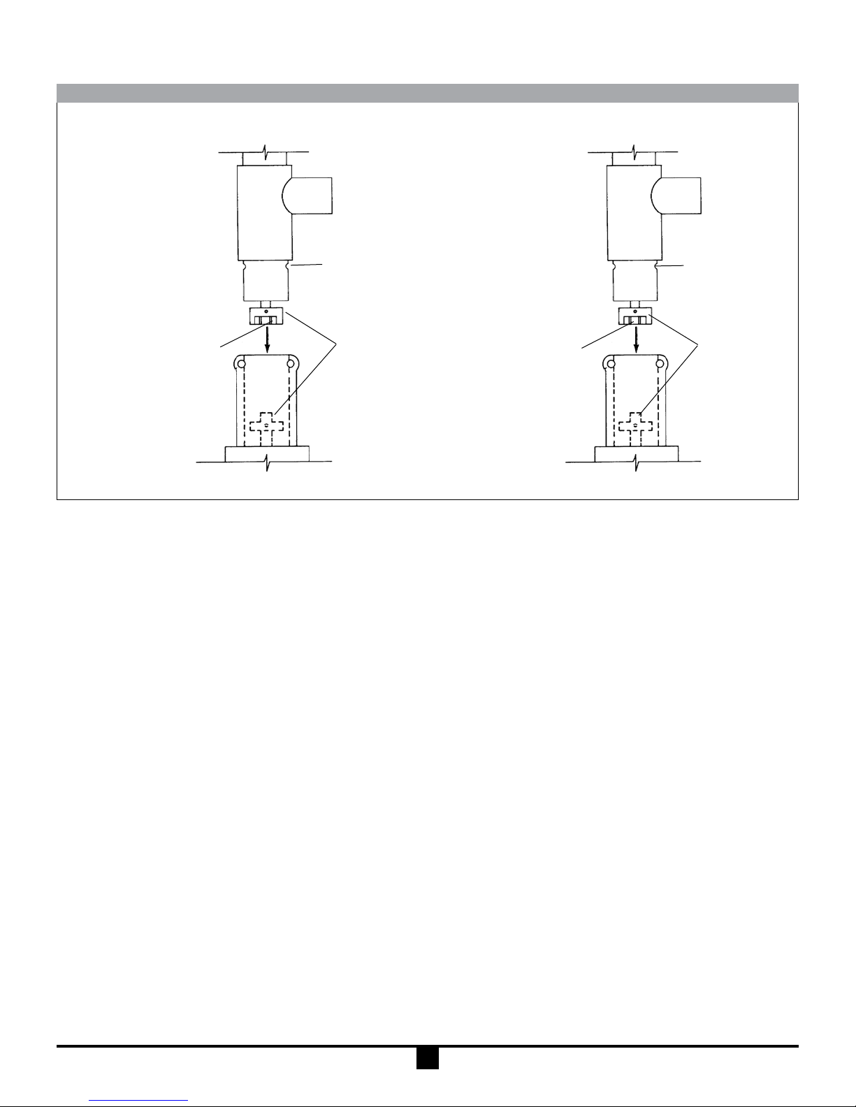
INSTALLATION INSTALACIÓN
TUBE
GROOVE
COUPLING
INSERT
2 PRONG
COUPLING
MOTOR WITH ADAPTER
Unpack motor from carton and check for shipping damage.
Unpack pump/mixer from carton. Check for shipping damage.
If any shipping damage is found, save the packaging and notify
the carrier immediately.
1. Ensure motor and pump compatibility. I.E., labeling.
2. Remove 2 socket head screws and nuts.
3. Ensure no obstructions on the coupling of either motor or
pump/mixer.
4. Position couplings and coupling insert for proper alignment.
5. Slide pump/mixer down into motor until couplings mate
and pump/mixer is seated properly. Refer to Figure 1.
6. Position motor so mounting holes line up with corresponding grooves on pump/mixer. (Note: Always position
electric cord away from discharge spout of pump.)
7. Install 2 socket head screws and nuts in mounting holes
and tighten securely.
8. Check to ensure that the motor is secured to the pump/mixer before operating. If not, repeat steps 1-6.
TUBO
RANURA
2 PUNTA
ACOPLADORA
Figure 1
INSERTO
ACOPLADOR
MOTOR CON ADAPTADOR
Saque el motor del cartón y revise por daños de embarque.
Saque la bomba (o mezclador) del cartón y revise por daños
de embarque.
Si se encuentran daños de embarque, póngase en contacto
con el suplidor del producto para reémplazarlo o reparario.
1. Asegúrese de la compatibilidad entre el motor y la
bomba. I.E. La etiqueta.
2. Remove 2 tornillos de cabeza de caquillo y tuercas.
3. Asegúrese de que no haya obstrucciones en el acoplador
de el motor o la bomba (o mezclador).
4. Coloque el acoplador y el inserto acoplador para una alineación correcta.
5. Deslize la bomba (o mezclador) hacia abajo en el motor
hasta que el acoplador y la bomba (o mezclador) esten
asentadas correctamente. Vea la Figura 1.
6. Coloque el motor para que los huecos de la estructura y las
ranuras correspondientes esten alineadas en la bomba (o
mezclador). (Note: Siempre coloque la conexión electrica
lejos del caño de descargar de la bomba.)
7. Instale 2 tornillos de cabeza de caquillo y tuercas en los
huecos de la estructura y aprietelos seguros.
8. Revise para asegurarse que el motor esté amarrado a la
bomba (o mezclador) antes de operar. Si no está, repita los
pasos 1-6.
8

M3 & M5 MODELS
Item M3 M5 Description Part Number
1 1 1 HSG Repair Kit A101493
2 1 1 Handle M101668
3 1 1 Switch A101690
4 1 1 Half Coupling J100012
5 1 – Cord Assembly A102050
5 – 1 Cord Assembly A102051
6 2 2 Brush 107764
7 6 6 Housing Nut J100990
8 4 4 Housing Screw J100022
9 2 2 Socket Head Cap Screw 108392
QuantityQuantity
Item M3 M5 Description Part Number
10 3 3 Screw J102275
11 1 1 Bearing Kit A101018
12 1 – Circuit Breaker w/Cover A100854
12 – 1 Circuit Breaker w/Cover A102182
13 1 1 Fan Blade J101510
14 1 1 Motor Fan Cover M101710
15 4 4 Cover Screw J101020
16 1 1 Handle Mounting Block M101666
17 2 2 Screw J103715
Note: Motor housing repair kits include motor covers, labels
and screws to repair the motor should it be damaged.
9

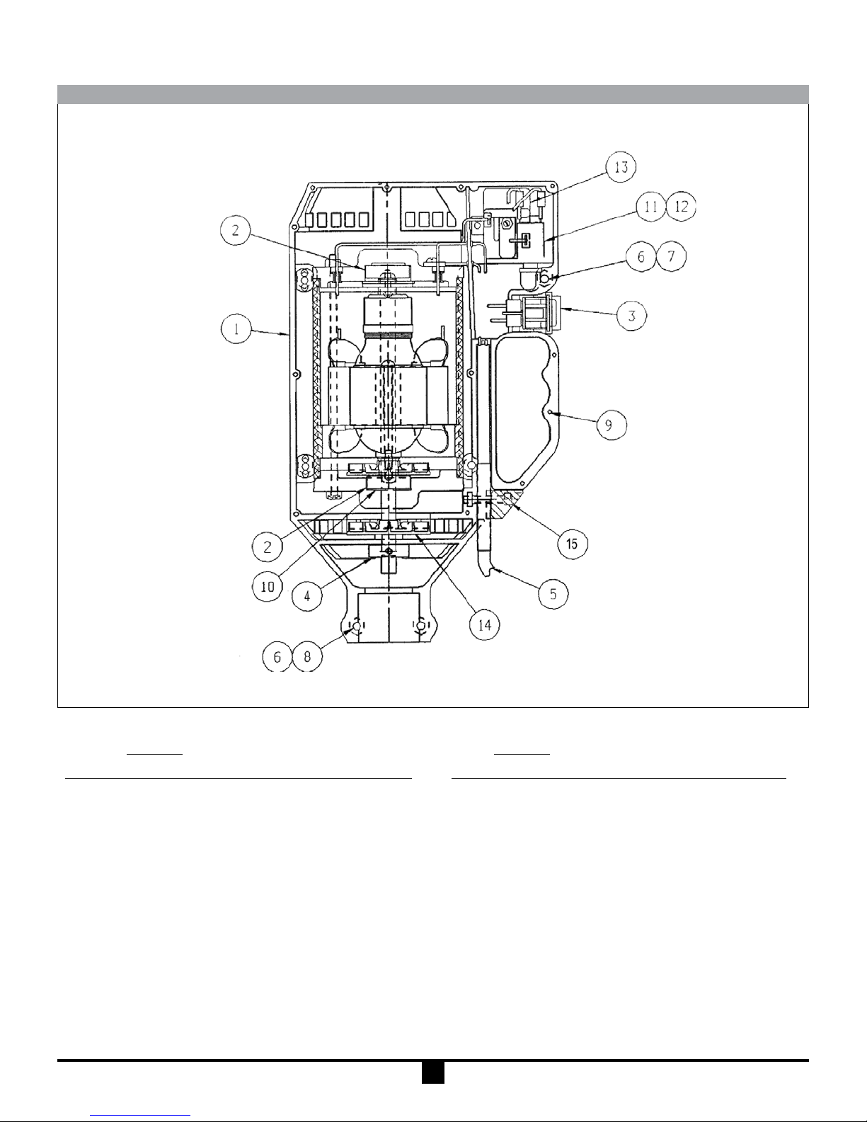
M3T & M5T MODELS
Quantity Quantity
Item M3T M5T Description Part Number
1 1 1 HSG Repair Kit A101416
2 2 2 Ball Bearing J101069
3 1 1 Switch A101690
4 1 1 Half Coupling J100013
5 1 – Cord Assembly A101738
5 – 1 Cord Assembly A101740
6 2 2 Brush J101107
7 6 6 Housing Nut J100990
Note: Motor housing repair kits include motor covers, labels and screws to repair the motor should it be damaged.
Item M3T M5T Description Part Number
8 4 4 Socket Head Cap Screw 108392
9 2 2 Mounting Bolt J101690
10 2 2 Screw J101530
11 1 1 Wave Washer J101126
12 1 – Circuit Breaker J103796
12 – 1 Circuit Breaker J101149
13 1 1 Cover J100789
14 1 1 Fan Blade J101094
15 2 2 Housing Bolt J100022
10
M7T MODELS
Quantity Quantity
Item M7T Description Part Number
1 1 Housing Repair Kit A101416
2 2 Ball Bearing J101069
3 1 Switch A101690
4 1 Half Coupling J100013
5 1 Cord Assembly A101748
5 – Cord Assembly A101751
6 6 Housing Nut J100990
7 4 Socket Head Cap Screw 108392
8 2 Mounting Bolt J101690
Notes: (1) Motor housing repair kits include motor covers, labels and screws to repair the motor should it be damaged.
(2) Contact factory for information on M8T.
Item M7T Description Part Number
9 2 Screw J101530
10 1 Wave Washer J101126
11 1 Circuit Breaker J101150
11 – Circuit Breaker J101149
12 1 Cover J100789
13 1 Start Relay J101147
13 – Start Relay J101804
14 1 Fan Blade A102024
15 2 Housing Bolt J100022
11

M6 MODEL
Quantity
Item M6 Description Part Number
1 1 Air Motor M101717
2 1 Pipe Nipple J100107
3 1 Hex Red. Bushing J100057
4 1 Ball Valve J100073
5 1 Hose Fitting J100036
6 1 Mufer J100033
7 2 Set Screw J100040
Not Shown: Air Motor Repair Kit J100060
Quantity
Item M6 Description Part Number
8 1 Air Motor Mount M100013-1
9 2 Socket Head Cap Screw 108392
10 2 Hex Nut J100990
11 1 Half Coupling J100013
12 1 Lubricator J100035
13 2 Pipe Nipple J102463
14 1 Filter J100034
12

M6X MODEL
Quantity
Item M6X Description Part Number
1 1 Air Motor M101720
2 1 Pipe Nipple J102463
3 1 Ball Valve J100073
4 1 Hose Fitting J100036
5 1 Mufer J100074
6 2 Set Screw J100040
7 1 Air Motor Mount M100013-2
Not Shown: Air Motor Repair Kit J100075
Quantity
Item M6X Description Part Number
8 2 Socket Hd. Cap Screw 108392
9 2 Hex Nut J100990
10 1 Half Coupling J101500
11 1 Lubricator J100035
12 2 Pipe Nipple J102463
13 1 Filter J100034
13

M3X, M5X, M7X & M10X MODELS
The “X” Series motor housing repair kit number is A101455.
Repairs to any item other than the thermoplastic enclosure
voids warranty.
Note: Motor housing repair kits include motor covers, labels
and screws to repair the motor should it be damaged.
M15-M40 MODELS
BT AIR
El kit de reparación del motor de la Serie “X” es A101455. El
hacer reparaciones a cualquier cosa aparte de la cubierta termoplástico anula la garantía.
M18 M15 M24
M19 M16 M25
M20 M17 M26
M27 M33
M28 M34
M29 M35
M39 (50 Hz)
M40 (50 Hz)
Air TEFC EXP
BT ELECTRIC
Please consult factory for repairs to any of the above listed
motors.
14
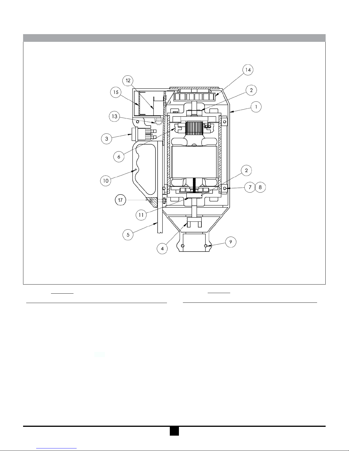
M58P-M59P MODELS
Quantity
Item M58P M59P Description Part Number
1 1 1 Housing Repair Kit 105145
2 1 1 Ball Bearing J101069
3 1 1 Switch A101690
4 1 1 Half Coupling J100013
5 1 – Cord Assembly A101738
5 – 1 Cord Assembly 106732
6 2 2 Brush J101107
7 6 6 Housing Nut J100024
8 4 4 Socket Head Cap Screw 108392
9 2 2 Mounting Bolt J101690
10 3 3 Screw J101530
Note: Housing Repair Kit includes motor covers, labels, & screws to
repair the motor should it be damaged.
Quantity
Item M58P M59P Description Part Number
11 1 1 Wave Washer J101126
12 1 – Circuit Breaker J103796
12 – 1 Circuit Breaker J101149
13 1 1 Cover J100789
14 1 1 Fan 105105
15 1 1 Speed Control 106086
15 1 – Potentiometer 108176-3
15 – 1 Potentiometer 108176-4
*16 1 1 Speed Control 108414
Knob & Cover
17 2 2 Housing Bolt J100022
*Not shown
15

STATIC PROTECTION KIT
EXPLOSION PROOF OR
GROUND WIRE ASSEMBLY
CLAMPED TO EARTH
GROUND
AIR MOTOR
GROUNDED HOSE
WITH GROUND WIRE
ASSEMBLY
GROUND WIRE ASSEMBLY
CLAMPED TO EARTH
GROUND
EXPLOSION PROOF OR
AIR MOTOR
GROUND
WIRE (NOT
INCLUDED)
EARTH GROUND
BONDING
WIRE (NOT
PROVIDED)
NO
SPLASHING
DRUM PUMP MIXER
DRUM PUMP INSTALLATION
1. Install the pump and Static Protection Kit as described and
shown.
2. Connect ground wire assembly to earth ground using supplied clamp.
3. Connect ground wire between drum and earth ground.
4. Connect ground wire between receiving container and earth
ground (or use bonding wire to connect to drum).
CAUTION - Check electrical continuity of all components
before pumping. All should be one (1) ohm or less.
GROUND WIRE
WITH PIPE
CLAMP (NOT
INCLUDED)
EARTH GROUND
OPERATION AND SAFETY GUIDELINES
• Use only metallic pump tubes with explosionproof motors to
transfer ammable or combustible liquids.
• Area for use must comply with NFPA 30 guidelines for safe
storage and use of ammable and combustible liquids.
• All containers and other equipment must be metal and
grounded.
• Follow NFPA 77 guidelines for control of static electricity.
• Avoid splashing. Splash lling can create static electricity
and is extrememly hazardous.
• Fluid velocity must be 3 feet/second maximum (7 GPM in
1" hose).
TUBE MIXER INSTALLATION
1. Install the mixer and Static Protection Kit as described and
shown.
2. Connect ground wire assembly to earth ground using supplied clamp.
3. Connect ground wire between drum and earth ground.
CAUTION - Check electrical continuity of all components
before pumping. All should be one (1) ohm or less.
1616

EQUIPO DE PROTECCIÓN ESTÁTICO
MOTOR CONTRA EXPLOSION
O DE AIRE
ALAMBRE DE CONEXION
A TIERRA
ALAMBRE
DE LINEA
(NO ESTA
INCLUIDO)
CONECCION DE TIERRA
MANGUERA CON
ALAMBRE DE LINEA
DE MONTAJE
ALAMBRE DE
PEGAR (NO
INCLUIDO)
NO SALPIQUEO
DRUM PUMP MIXER
INSTALACIÓN DE LA BOMBA DE MOTOR
1. Instale la bomba y el Equipo de Protección Estático como se
describe y se muestra.
2. Conecte el alambre a la conección de tierra, usando la grapa
que se le ha surtido.
3. Conecte el alambre de tierra entre el tambor y la conexión de
tierra.
4. Conecte el alambre de tierra entre el recipiente recibidor y la
conección de tierra (o use alambre de pegar para conectar al
tambor).
CUIDADO - Revise la continuadad eléctrica de todos los
componentes antes de bombear. Todos deben ser un (1) ohm
o menos.
MOTOR CONTRA EXPLO-
SION O DE AIRE
ALAMBRE DE CONEXION
A TIERRA
ALAMBRE
DE LINEA
CON GRAPA
DE PIPA (NO
INCLUIDA)
CONECCION DE TIERRA
GUIAS DE OPERACIÓN Y SEGURIDAD
• Use solamente tubos de bomba metálicos con motores contra
explosivos para transferir líquidos combustibles o inam-
ables.
• El lugar de uso debe estar de acuerdo con las normas NFPA
30, para almacener seguramente líquidos combustibles y
inamables.
• Todo recipiente y otro equipo debe ser de metal y conectado
a tierra.
• Siga las guias NFPA 77 para el control de electricidad estática.
• Evite salpiquear. El llenar con salpiquéo puede crear electricidad estática y es extremamente peligroso.
• La velocidad del fuido debe ser de 3 pies/segundo máximo
(7 GPM en manguera de 1").
INSTALACIÓN DEL MEZCLADOR
1. Instale la mezcladora y el Equipo de Protección Estático
como se describe y se muestra.
2. Conecte el alambre a la conección de tierra, usando la grapa
que se le ha surtido.
3. Conecte el alambre de línea entre el tambor y la conexión de
tierra.
CUIDADO - Revise la continuadad eléctrica de todos los
componentes antes de bombear. Todos deben ser un (1) ohm
o menos.
17

TECH SERVICE 1-800-888-3743
FT96-593M, J102516, Rev. 27, 7/15/2016
18
 Loading...