


401 Andover Park East
USA (206) 246-2010
Original Instruction
UNCONTROLLED IF PRINTED
Seattle, Washington 98188-7605
FTI OPERATIONS, MAINTENANCE, AND REPAIR MANUAL
Little Brute Right Angle Puller (LBRA-7)
Part #2720-114, Log #36106
#568209 Revision C
February 27, 2019
NO REVISIONS WILL BE ISSUED
This manual should be used in conjunction with the FTI
“Little Brute Puller Unit Operations, Maintenance, and Repair Manual”
© Copyright 2019
Fatigue Technology
Al
l Rights Reserved

UNCONTROLLED IF PRINTED
ABOUT FATIGUE TECHNOLOGY
Fatigue Technology (FTI) is a world-leading aerospace engineering and manufacturing company. FTI pioneered cold
expansion technology (which provides solutions to fatigue problems associated with holes in metal structures) back in 1969
and has advanced this science to develop innovative bushing and fastener products. These proprietary products and
associated tooling may be covered by patents or agreements owned by or exclusively licensed to Fatigue Technology. Use of
tooling procured from other than a licensed source may constitute patent infringement.
The detailed tooling information in this manual was compiled and written by FTI. The tooling was designed specifically for
use with FTI’s Cold Expansion (Cx™) Systems. FTI cannot be held responsible for damage or injury as a result of operating
this equipment if it is used for other than the process intended, with any other tooling not provided by FTI, or not used in
accordance with the instructions contained in this manual. To avoid personal injury, please observe all safety precautions and
instructions. FTI reserves the right to change specifications or configurations of equipment detailed in this manual as part of
our ongoing technical and product improvement programs. If you have any questions about the use or serviceability of this
equipment, please contact our Sales Department.
FTI’s systems and processes are the subject matter of one or more of the following patents: 4,809,420, 4,885,829,
4,934,170, 5,083,363, 5,096,349, 5,103,548, 5,127,254, 5,129,253, 5,218,854, 5,245,743, 5,305,627, 5,341,559,
5,380,136, 5,405,228, 5,433,100, 5,468,104, 6,077,010, 6,183,180, 6,487,767, 6,792,657, 6,990,722, 7,024,908,
7,100,264; 1,061,276, 513,898, 692015124, 581,385, 69310828, 468,598, 69105390, 643,231, 69414946, 696,686,
785,366, 1032769, and other patents pending. These systems and processes are tooling critical and must be performed in
accordance with FTI’s specifications or controlling documents. To ensure proper results from FTI’s cold expansion systems
and to be licensed to use FTI’s patented processes, it is essential that FTI’s complete integrated system of tooling be
purchased and utilized. The use of tooling purchased from other than a licensed supplier could jeopardize fatigue life
enhancement and may constitute patent infringement.
Fatigue Technology Inc. 401 Andover Park East Seattle, WA • USA 98188-7605 Tel: (206)246-2010 Fax: (206)244-9886
568209-REV C

UNCONTROLLED IF PR
F
TI reserves the right to change the specifications or configurations of tooling detailed in this manual as part of its ongoing
INTED
technical and product information program. Should inconsistencies occur between your tooling and this manual, please
contact our Sales Department.
atigue Technology (FTI) has provided innovative solutions to fatigue problems in metal structures since 1969. Complete
F
systems of tooling are used worldwide to enhance the fatigue life of holes in airframes, turbine engines, and other critical
structures.
T
he FTI staff of professionals provides a full range of support services including:
• Application engineering
etailed project planning, implementation, and management
• D
• On-site assistance, including training and tool room setup
T
he Sales Department is always available to assist with special fatigue enhancement requirements. Please contact FTI with
questions at any time.
Fatigue Technology Inc. 401 Andover Park East Seattle, WA • USA 98188-7605 Tel: (206)246-2010 Fax: (206)244-9886
568209-REV C

This page intentionally left blank for two-sided printing.
Fatigue Technology Inc. 401 Andover Park East Seattle, WA • USA 98188-7605 Tel: (206)246-2010 Fax: (206)244-9886
568209-REV C

UNCONTROLLED IF PRINTED
TABLE OF CONTENTS
SECTION DESCRIPTION PAGE
1.0 Introductory Information - Little Brute Right Angle Puller.......................................................................................................................... 1
2.0 Safety ........................................................................................................................................................................................................... 2
3.0 LBRA-7 Specifications and Dimensions ...................................................................................................................................................... 5
4.0 Assembly of the LBRA-7 onto a Little Brute Puller .................................................................................................................................... 6
5.0 Assembly and Maintenance ......................................................................................................................................................................... 9
6.0 Illustrated Parts Breakdown ....................................................................................................................................................................... 12
FIGURES
Figure 2.0-1 Safety Stickers ............................................................................................................................................................................................. 3
Figure 3.0-1 LBRA-7 Dimensions ................................................................................................................................................................................... 5
Figure 4.0-1 Little Brute Puller Unit, Endcap Removed ................................................................................................................................................... 6
Figure 4.0-2 Little Brute Puller Unit and Threaded Adapter ............................................................................................................................................ 7
Figure 4.0-3 LBR A-7, Installation Diagram ..................................................................................................................................................................... 8
Figure 5.1-1 Retaining Ring Removal .............................................................................................................................................................................. 9
Figure 5.2-1 Greased Internals ....................................................................................................................................................................................... 10
Figure 6.0-1 LBRA-7 Illustrated Parts Breakdown ........................................................................................................................................................ 12
Fatigue Technology Inc. 401 Andover Park East Seattle, WA • USA 98188-7605 Tel: (206)246-2010 Fax: (206)244-9886
568209-REV C

UNCONTROLLED IF PRINTED
TABLE OF CONTENTS (CONTINUED)
SECTION DESCRIPTION PAGE
TABLES
Table 3.0-1 LBRA-7 Specifications ................................................................................................................................................................................. 5
Table 6.0-1 LBRA-7 Parts List ...................................................................................................................................................................................... 13
Fatigue Technology Inc. 401 Andover Park East Seattle, WA • USA 98188-7605 Tel: (206)246-2010 Fax: (206)244-9886
568209-REV C

UNCONTROLLED IF PR
INTED
SECTION 1.0: INTRODUCTORY INFORMATION—LITTLE BRUTE RIGHT ANGLE PULLER
This instruction manual contains information on the operation and maintenance of the Little Brute Right Angle Puller (LB RA-7) designed by Fatigue
Technology Inc. (FTI) for use with the patented Split Sleeve Cold Expansion™ (SsCx™) process. To obtain optimum performance and many years of
trouble-free service, carefully follow maintenance procedures and operate the LBRA properly.
R
ead this manual before operating the LBRA, and retain the manual for future reference. If requested, FTI will provide this manual in the language of the
end-user.
T
he Little Brute Right Angle Puller is a compact, durable tool that enables coldworking in restricted access areas that are difficult or impossible to get to
with conventional tools.
• Is capable of cold expanding holes in restricted access areas up to 0.40-inch (10.16 mm) in diameter in aluminum and mild steel.
• Attaches to the Little Brute (LB) series of puller units. See the Little Brute Puller Unit Operations, Maintenance, and Repair Manual for additional
safety information.
• The Right Angle Puller alone weighs approximately 2.0 pounds (0.91 kg); with the Little Brute Puller Unit, it weighs approximately 12.0 pounds
(5.44 kg).
equires only 0.350-inch (8.89 mm) lateral clearance (see Figure 3.0-1).
• R
• Head can rotate 360 degrees on the puller unit.
• Has a maximum pull force of 3,400 pounds (maximum generated by the Little Brute Puller Unit).
• T
he LBRA-10 is capable of much more pull force than the LBRA-7 and is physically larger. For high-force applications, an LBRA-10 may be better
suited. This manual only covers the LBRA-7 and does NOT apply to the LBRA-10.
Fatigue Technology Inc. 401 Andover Park East Seattle, WA • US A 98188-7605 Tel: (206)246-2010 Fax: (206)244-9886
568209-REV C 1

UNCONTROLLED IF PRI
NTED
SECTION 2.0: SAFETY
afe operation of the LBRA is of paramount concern. Along with standard shop safety practices (eye protection, safe handling of high-pressure equipment,
S
etc.), the following items are peculiar to the LBRA/puller unit assembly:
1
. Wear eye protection when operating the puller unit.
. Disconnect the air supply when:
2
Maintenance is to be performed
Hydraulic hose is disconnected
PowerPak is not in use
. Disconnect the LB Puller Unit from the PowerPak before attaching the LBRA.
3
. Set the maximum operating pump pressure to 4,250 psi (29.31 MPa). Refer to the FT-200 PowerPak Operations, Maintenance, and Repair
4
Manual.
. In the event of a ruptured or leaking hydraulic hose, IMMEDIATELY RELEASE THE TRIGGER AND DISCONNECT THE AIR LINE at the air
5
coupler from the PowerPak. Never use your hands to grasp a leaking hose under pressure. The force of escaping hydraulic fluid could cause serious
injury.
6. Keep hands away from the nosecap assembly while holding the nosecap against the workpiece.
7
. Release the puller unit trigger when the mandrel clears the workpiece or becomes stuck.
8
. The Little Brute end cap must always be in place while in use. Injury may occur if the end cap is removed during operation.
. Before operating the pump, tighten all hose connections using the proper tools. Do not over-tighten the connections. Connections need only be
9
tightened securely and leak-free. Over-tightening may cause premature thread failure or high-pressure fittings to split at pressures lower than their
rated capacities.
Fatigue Technology Inc. 401 Andover Park East Seattle, WA • US A 98188-7605 Tel: (206)246-2010 Fax: (206)244-9886
568209-REV C 2

UNCONTROLLED IF PRINTED
0. Operators must read this manual in its entirety before using the Little Brute Right Angle Puller. Eye and ear protection must be worn while operating
1
the Little Brute. Three safety stickers on the Little Brute Puller Unit series act as a reminder to these instructions. The symbols are shown in Figure
2.0-1.
11. Do not use in potentially explosive atmospheres.
R
ead manual before using Always wear eye protection Always wear ear protection
Figure 2.0-1
Safety Stickers
Fatigue Technology Inc. 401 Andover Park East Seattle, WA • US A 98188-7605 Tel: (206)246-2010 Fax: (206)244-9886
568209-REV C 3

UNCONTROLLED IF PRINTED
Hydraulic Hose Safety
1. Inspect the hydraulic hose for signs of wear (cuts, abrasions, or kinks) to the outer shell material. Pump clean oil through the entire length.
Pressurize the hose and check for leaks at the crimped connectors, between the hose material and the fitting, and between the fitting and the coupler.
. DO NOT attempt to disconnect the hydraulic hose while it is under pressure.
2
DO NOT expose hoses to potential hazards, such as extreme heat or cold, sharp surfaces, or heavy impact.
D
O NOT allow hoses to kink, twist, curl, or bend so tightly that the oil flow within the hose is blocked or reduced. Periodically inspect the hose for
wear or damage that could cause premature failure of the hose and possibly result in injury. Damaged hoses must be replaced immediately.
DO NOT use the hose to move attached equipment.
D
O NOT remove the strain reliever from hoses.
3
. Hose strain relievers must be placed around hose fittings during use. Hoses with damaged strain relievers must be replaced immediately.
. Hose material and coupler seals must be compatible with hydraulic fluid that meets the requirements of MIL-PRF-5606.
4
. Hoses must not come in contact with toxic materials, such as creosote-impregnated objects and some paints. Keep couplers and hoses clean and fr
5
o
f paint. Hose deterioration due to chemical degradation may cause the hose to fail under pressure. Damaged hoses must be replaced immediately.
. Before operating the PowerPak, make sure all hose connections are tightened securely. DO NOT over-tighten.
6
. If hoses require replacement, contact the FTI Sales Department.
7
MPORTANT: FTI completed a risk assessment on this unit at our factory. Any modifications done by a third party or the final user are excluded from
I
that risk assessment.
ee
Fatigue Technology Inc. 401 Andover Park East Seattle, WA • US A 98188-7605 Tel: (206)246-2010 Fax: (206)244-9886
568209-REV C 4
Right Angle
Width [W]
Adapter Length
[L]
Frontside
Clearance [F]
Maximum Pull
Force
Mini mum Edge
Distance
Max Stackup:
4-0-N to 8-1-N
Max Stackup:
8-2-N to 12-3-N
Mandrel and Nosecap Selection
UNCONTROLLED IF PRINTED
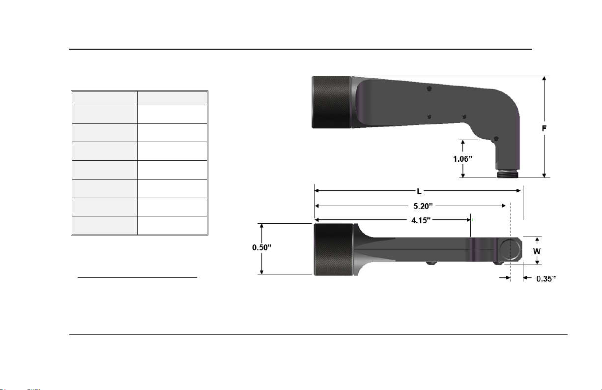
SECTION 3.0: LBRA-7 SPECIFICATIONS AND DIMENSIONS
Table 3.0-1
LBRA-7 Specifications
Model Number LBRA-7
0.80"
5.55"
3.0"
3,400 Pounds
0.350"
0.840"
0.715"
The LBRA uses special LBRA mandrels and nosecaps.
Refer to the FTI Tooling Catalog.
Nosecaps: Section 2.3.40
Mandrels: Section 2.3.22
Figure 3.0-1
LBRA-7 Dimensions
Fatigue Technology Inc. 401 Andover Park East Seattle, WA • US A 98188-7605 Tel: (206)246-2010 Fax: (206)244-9886
568209-REV C 5

UNCONTROLLED IF PRINTED
SECTION 4.0: ASSEMBLY OF THE LBRA-7 ONTO A LITTLE BRUTE PULLER
o install the LBRA-7 onto the Little Brute puller:
T
CAUTION: Before attempting any maintenance operations on the puller unit disconnect the PowerPak from the air supply or disconnect the puller
. Remove all tooling from the barrel end of the Little Brute.
1
. Using a spanner wrench, loosen the lock ring on the back of the Little Brute and remove the endcap (Figure 4.0-1). A large flat screwdriver fits into
2
the slot on the back of the piston to keep it from rotating.
from the PowerPak or hand pump.
Figure 4.0-1
Little Brute Puller Unit, Endcap Removed
Fatigue Technology Inc. 401 Andover Park East Seattle, WA • US A 98188-7605 Tel: (206)246-2010 Fax: (206)244-9886
568209-REV C 6

LB-D10 Threaded Adapter
UNCONTROLLED IF PRINTED
3. Ensure the threaded adapter, LB-D10, is attached to the piston rod of the LB puller unit (Figure 4.0-2). Tighten securely while using a large flat
screwdriver on the back of the Little Brute to keep the piston from rotating.
Figure 4.0-2
Little Brute Puller Unit and Threaded Adapter
Fatigue Technology Inc. 401 Andover Park East Seattle, WA • US A 98188-7605 Tel: (206)246-2010 Fax: (206)244-9886
568209-REV C 7

UNCONTROLLED IF PRINTED
4. Thread the LBRA rod into the threaded adapter while using a large flat screwdriver on the back of the Little Brute to keep the piston from rotating
(Figure 4.0-3 - Top). Once the LBRA rod is fully threaded onto the unit, thread the LBRA end cap onto the male threads on the Little Brute Puller
Unit barrel. Re-install the Little Brute endcap and tighten the lock ring securely with a pinwrench. THE ENDCAP MUST BE IN PLACE DURIN
ERATION. The installation is now complete.
OP
5. See Little Brute Manual for operation and use of assembled tooling.
Figure 4.0-3
LBRA-7, Installation Diagram
G
Fatigue Technology Inc. 401 Andover Park East Seattle, WA • US A 98188-7605 Tel: (206)246-2010 Fax: (206)244-9886
568209-REV C 8
UNCONTROLLED IF PRINTED
SECTION 5.0: ASSEMBLY AND MAINTENANCE
CAUTION: Before attempting any maintenance operations on the puller unit disconnect the PowerPak from the air supply or disconnect the puller
efer to Figure 6.0-1 for identification of the components.
R
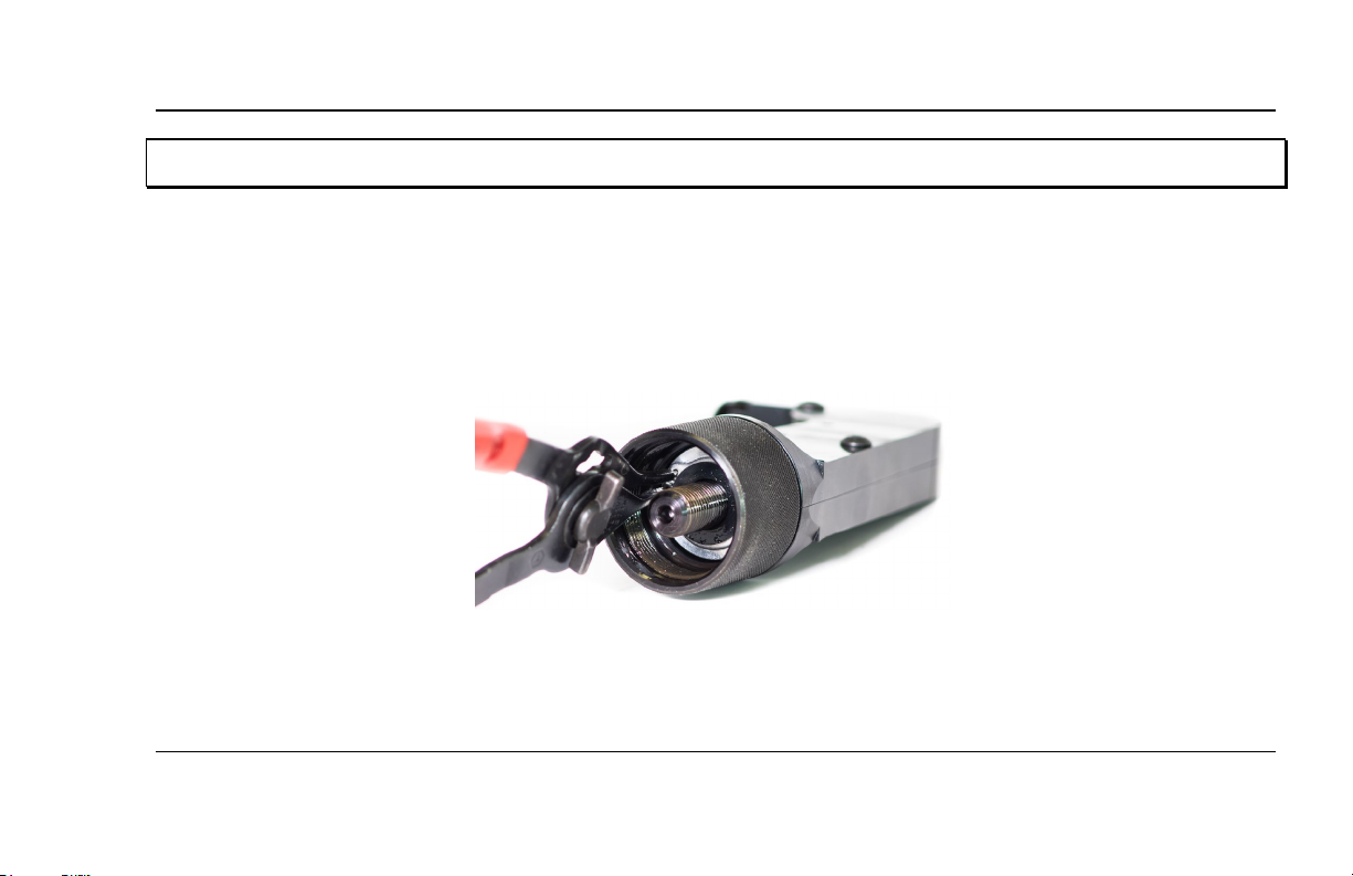
5. 1 D
. To disassemble the LBRA-7, first remove it from the Little Brute. If a nosecap is mounted, take it off as well.
1
. Remove the retaining ring (9) using retaining ring pliers (Figure 5.1-1). The end cap (10) can now be removed along with the O-ring (7) and
2
washer (8).
from the PowerPak or hand pump.
isassembly
Figure 5.1-1
Retaining Ring Removal
. Remove the two screws in the left half of the housing. The left housing can now be removed and the internal parts accessed for maintenance.
3
Fatigue Technology Inc. 401 Andover Park East Seattle, WA • US A 98188-7605 Tel: (206)246-2010 Fax: (206)244-9886
568209-REV C 9
Grease
ONTROLLED IF PRINTED
UNC
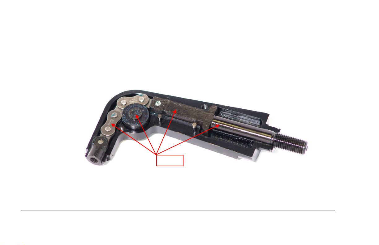
5.2 Cleaning and Lubrication
The puller requires routine checking and periodic preventative maintenance to ensure safe, trouble-free operation. No special maintenance is required. The
following maintenance actions are suggested.
. Periodically clean the outer surfaces of the unit. Keep all hose connections free of dirt and grime. Doing so will dramatically extend the life of
1
pumps and puller seals.
. The internal moving parts should be periodically lubricated with Mobil-HP or equivalent grease to ensure smooth operation and extend the life of
2
the unit (Figure 5.2-1).
Figure 5.2-1
Greased Internals
. Whenever the puller unit is to be stored for any length of time, maintain a thin coat of 10-weight oil on the outside surfaces to prevent rusting.
3
Fatigue Technology Inc. 401 Andover Park East Seattle, WA • US A 98188-7605 Tel: (206)246-2010 Fax: (206)244-9886
568209-REV C 10

UNC
ONTROLLED IF PRINTED
5.3 Replacing Parts/Repair
If parts need replacing or the unit needs repair, please contact FTI’s Sales Department. FTI will work with the operator to try to troubleshoot over the phone,
but a return of the LBRA unit may be required.
5.4 Reassembly
. Replace all internal components into the right half housing.
1
. Attach the left housing half using the two screws.
2
3. Install the end cap (10), followed by the O-ring (7) and washer (8). Ensure that the O-ring and washer are fully seated all the way down.
4
. Install the retaining ring (9) using retaining ring pliers. The O-ring must be compressed to fit the retaining ring on, so it may be necessary to tap
the retaining ring with a blunt pin until the ring is fully snapped into the groove.
Fatigue Technology Inc. 401 Andover Park East Seattle, WA • US A 98188-7605 Tel: (206)246-2010 Fax: (206)244-9886
568209-REV C 11
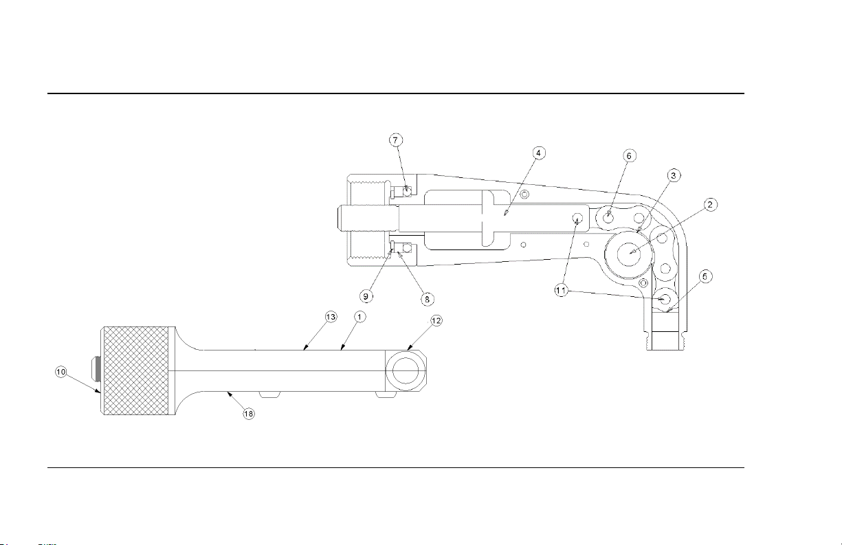
Figure 6.0-1
LBRA-7 Illustrated Parts Breakdown
UNCONTROLLED IF PR
INTED
SECTION 6.0: ILLUSTRATED PARTS BREAKDOWN
diagram is provided in Figure 6.0-1 and parts list in Table 6.0-1. The Little Brute Right Angle Puller Unit is compact and tight, and as a result, it could be
A
difficult to open and repair. Please contact FTI for any assistance.
Fatigue Technology Inc. 401 Andover Park East Seattle, WA • US A 98188-7605 Tel: (206)246-2010 Fax: (206)244-9886
568209-REV C 12

Quantity
LBRA-7
LBRA-7-PC-12
LBRA-7-BH-1
LBRA-7-PC-8
1 1 -
1
5295-001
- - 1
-
5295-002 2 1 1 1
1
5300-001
Pin, Roller
3 1 1 1 1
5299-001
Roller
4 1 1 1 1
5298-001
Adapter, Puller
1 - 1
-
5294-001
- 1 -
-
5294-002 - - - 1
5294-003 6 1 1 1
1
5305-001
Chain
7 1 1 1 1
1046-120
O-Ring
8 1 1 1 1
5301-001
Washer, LBRA Tension
9 1 1 1 1
1045-366
Ring, External Retaining
10 1 1 1 1
5304-001
LBRA End Cap
11 2 2 2 2
1045-367
Dowel Pin
12 1 1 1 1
1009-185
Caution Label
13 1 1 1 1
1009-255
Pressure Label
14 1 1 1 1
1199-452
Case
15
1
1 1 1
1009-293
FTI Label
16 1 1 1 1
1009-307
LBRA-7 Label
17 1 1 1 1
2720-114
Manual, LBRA-7
18 1 1 1 1
1166-001
Label, CE
UNCONTROLLED IF PRI
Table 6.0-1
LBRA-7 Parts List
NTED
Item Number
1
5
Fatigue Technology Inc. 401 Andover Park East Seattle, WA • US A 98188-7605 Tel: (206)246-2010 Fax: (206)244-9886
568209-REV C 13
Part
Number
Description
Housing Sub-Assembly
Adapter, Mandrel Link

E.C. DECLARATION OF CONFORMITY
FATIGUE TECHNOLOGY INC.
Manufacturer: Fatigue Technology Inc.
401 Andover Park East
Seattle, WA 98188-7605
Telephone: (206) 246-2010
Fax: (206) 244-9886
Responsible Person in E.C.: Jean-Michel Derisson
4 rue d’Austerlitz
31490 Léguevin
FRANCE
Telephone: 33 5-34-559-916
Fax: 33 5-34-569-047
401 Andover Park East
Seattle, Washington 98188-7605
USA
The undersigned declares that the machinery described:
Type:
Serial Number:
Conforms to the following directives:
Council Directive 2006/42/EC (the Machinery Directive)
ISO 11148-1 Hand-Held Non-Electric Power Tools – Safety Requirements – Part 1
ISO 4413 Hydraulic fluid power – General rules and safety requirements for
systems and their components
ISO 4414 Pneumatic fluid power – General rules and safety requirements for
systems and their components
And complies with the relevant health and safety requirements.
Jeff Sageman Date
Logistics Manager
4/25/19
 Loading...