

Page 1
FST
Sensors
wIR-3 Gateway
03-02-2017
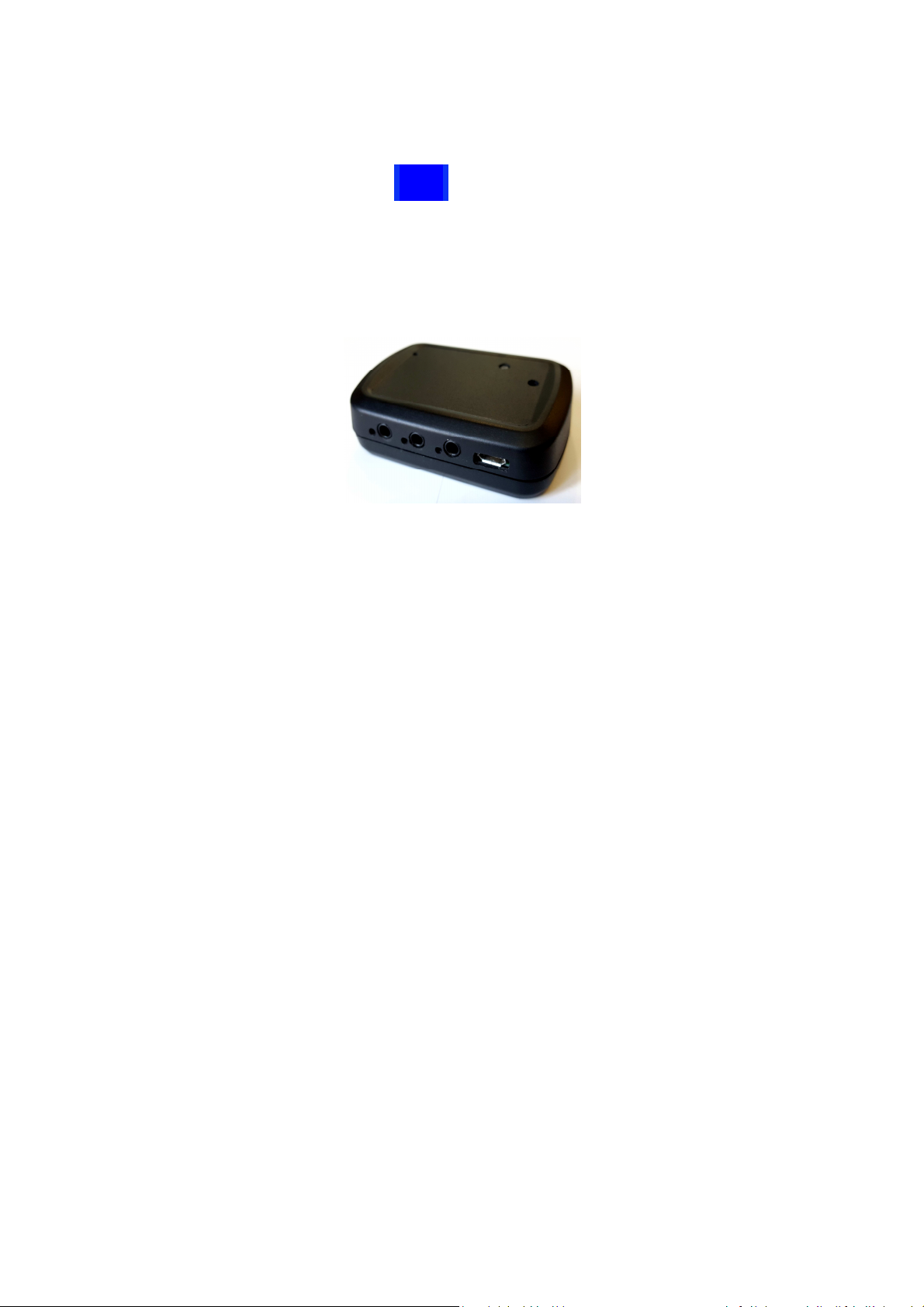
The wIR-3 Gateway allows control of infrared devices via a Wi-Fi network. The W-IR3 has 3 independent
3.5mm standard IR emitter ports. The unit is designed around open system standards and allows easy
integration with smart phones and PC using industry standard IR control software applications. The
wIR-3 utilizes a built in web browser for system setup and web browser utilities for learning/converting
IR codes along with built in communication monitoring for debugging and support.
Page 2

Contents
Features .................................................................................................................................................. 3
Specification ............................................................................................................................................ 3
Getting Started ........................................................................................................................................ 3
Ad-Hoc mode - Setup .............................................................................................................................. 3
WiFi Setup ............................................................................................................................................... 4
Logging in using the “Access Point/Device Name”: ............................................................................... 7
Logging in using the “IP Address”: ........................................................................................................ 7
IR Senders/Blasters ................................................................................................................................. 8
iRule setup .............................................................................................................................................. 9
Simple Control (roomie) setup ................................................................................................................. 9
IR Gateway Commands ............................................................................................................................ 9
IR Leaner ........................................................................................................................................... 11
IR Format breakdown ........................................................................................................................ 13
System Log ............................................................................................................................................ 14
Firmware Update .................................................................................................................................. 15
Page 3

Features
Input power
5 to 9
VDC@350mA, Micro USB input connector, Standard PC USB can supply power
LED Activity LED (WiFi, Lea
rn), 3 LED indicators one for each IR connector
Setup/Test
Built in web server for configuration of network settings, IR Learning and format
WiFi Network
2.4GHz
802.11b/g
/n, supporting
WPA/WPA2
wireless network
IR ports
3 b
uilt in independent
3.5mm jacks, standard IR flashers and IR Blasters
IR Formats
Industry standard Pronto HEX
,
Global Cache
and GC Compressed
formats
IR Learning
Built in web based IR learning, code format conversion and testing
Dimensions
2”L x 3”W x .75”H
Warranty
2 year limited warranty
Certifications
Radio c
omplies with FCC part 15, Class B
The wIR-3 has a built in web server that allows for easy setup/configuration/test as well as IR Learning
and format conversion via a web browser without the need for separate program. Up to 8 clients can be
connected at the same time. The unit also has a client log that will display the last 20 commands sent to
the wIR-3 unit. The wIR-3 has 3 independent 3.5mm ports to support IR emitters and IR blasters without
the need for additional splitter cables.
Specification
conversion
RoHs compliant
Getting Started
First time power up the wIR-3 will be in unsecured Ad-Hoc mode and can be discovered from any
wireless smart phone, tablet or laptop. Connect the power supply to the W-IR3 and the 3 Led’s near the
3.5mm jacks will sequence and the BLUE LED on the top of the W-IR3 will flash twice a second indicating
the unit is in Ad-Hoc mode.
Ad-Hoc mode - Setup
Forcing into Ad-Hoc mode, press the setup button, the Blue LED will flash fast, keep holding the setup
button for 5 seconds and when all the IR LED’s flash rapidly, release the setup button and the Blue LED
should flash twice a second indicating setup more.
Page 4
WiFi Setup
While the unit is in Ad-Hoc mode (BLUE LED flashing fast), Use a Wi-Fi enabled device like a smart
phone, laptop or tablet to finish the setup.
•
On your Wi-Fi device, navigate to the Wi-Fi setup/available networks
•
On your Wi-Fi device find the network that starts with “FST” and will look something like “FSTEB1A”. Note the last 4 characters are unit dependent and can be found on the label on the back
of the unit.
•
Select/Connect to the FST-XXXX network from your wireless device
•
When your device asks for the network password for FST-XXXX enter the default password of
12345678
•
And connect to the unit
•
After the connection is established (your Wi-Fi device should state “Connected”)
•
Open a internet browser like Chrome or Safari on your device
•
Enter the Ad-Hoc mode default IP address in the url 192.168.4.1
•
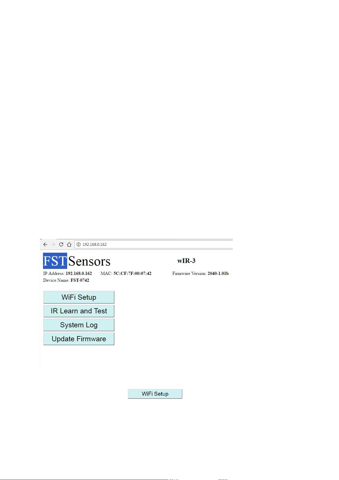
Hit enter and the W-IR3 setup page should be displayed
To exit Ad-Hoc mode, press the setup button again and the blue LED will flash rapidly, release the
button and the unit will reboot.
This will bring up the following screen.
From the main page you can select
Page 5
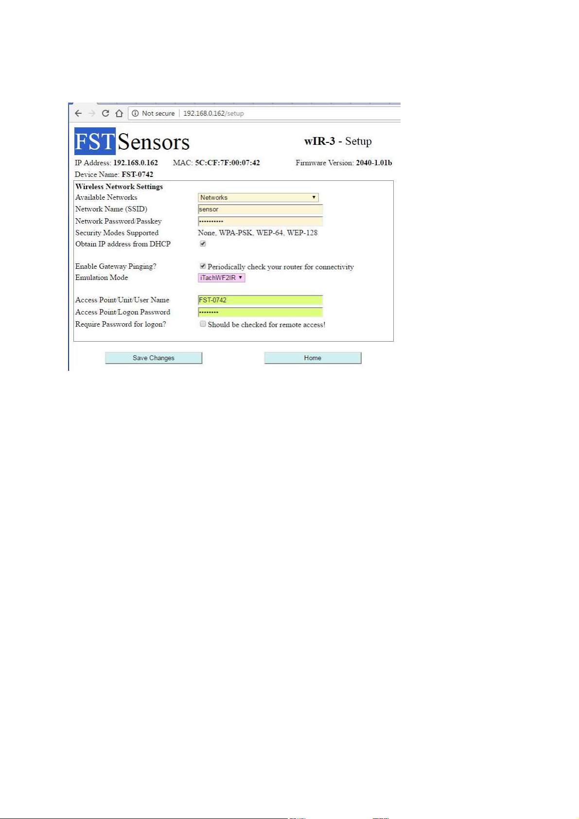
1. Select your Network you want to connect to from the pull down list in “Avalible Networks” or
type in the network name if the Network Name (SSID) field. The signal strenght of the avalible
networks will be on the right side of the name, were -40dBm is very strong and -90dBm is very
weak network.
2. Enter the Password/Passkey for your network in the Network Password/Passkey field.
3. The “Obtain IP Address from DHCP” is checked, which will use the IP address that your router
assigns. If you un-check the “Obtain IP Address from DHCP”, you will can enter in the fixed IP
address, Gateway and DNS.
Page 6
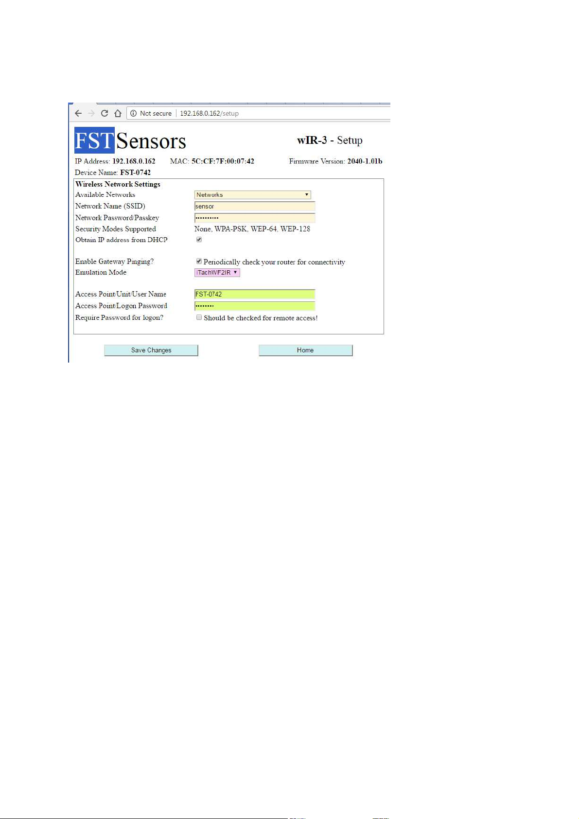
4. The “Enable Gateway Pinging” check box will send a PING to the IP address of your gateway
(wireless router) every 3 minutes, if your router does not respond the wIR-3 will try to reestablish connection.
5. The “Emulation mode” is used for compatiblity to other IR Gateways. If using programs like
Simple Control (roomie) set the emulation to iTachWF2R.
6. The “Device Name” can be changed from the the default, this can be used for logging into the
unit from a browser instead of using the IP address and in AP setup mode. Don’t uses spaces in
the name if you are going to log into the unit by name in the URL, use underscores. Example
Closet_2
7. If you want to enable password logon to the W-IR3 through a web browser, check the “Require
Password for Logon” check box. The defualt password is “12345678”. Note: Client
connections thorugh port 4998 do not require user name and password.
8. Save the changes by clicking the “Save Changes and Reboot” button located at the bottom right
of the setup page.
Make sure your network name and password are correct as well as the rest of the network settings.
Lower and upper case characters make a difference in your user name and password.
Note: The unit will reboot after 2 and a half minutes if it does not connect to your network and try to
connect again.
If the Blue LED is flashing slowly, you are connected to your network. You can log into your network
from any computer on your network, (tablet, desk top PC or Smartphone) by using the IP address or the
“Access Point/Unit Name”.
Page 7
If you selected DHCP your router will assign the IP address, you will need to know the IP address so you
can send IR commands to. To find the IP address can be accomplished a few different ways.
Finding my IP address
•
You can use a discovery beacon program to locate the W-IR3 on your network.
•
You can log into the unit using the Access Point/Device Name from the url, default name is
located on the bottom of the unit.
•
You can log into your Wireless Router and locate the device in the attached device listing
•
You can force the unit back into Ad-Hoc mode and un-check the “Obtain IP Address from DHCP”
and the IP address will be preset for you.
Logging in using the “Access Point/Device Name”:
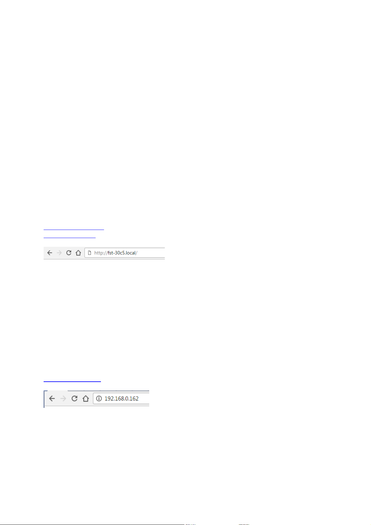
Assuming the “Access Point/Device Name” is “FST-0742”Type the following address into your browser
upper/lower case characters do not matter for the unit name. If you change the “Access Point/Unit
Name”, use the new name you created and add the .local/ to the end when your entering it in the
browser. Make sure you add the http:// to the front and .local/ to the end.
Examples logging in using unit name:
http://FST-0742.local/
http://Closet.local/
Hit enter and the unit should display the Sensor Status screen. Note: if the browser takes you out to the
internet to search for “FST-30C5.local” then try logging into the unit using the IP Address.
Logging in using the “IP Address”:
If you set a fixed “IP Address” during setup you can type that in your browser. If you check “Obtain IP
address from DHCP” (which is default) you can log into the sensor in AP mode again and the last IP
address assigned from your wireless router can be found in the “IP Address” field at the top of the
configuration page. Note: you can make setup changes in AP mode, but you cannot send/test emails or
text message as well as receive the NTP time, the unit must be in normal operating mode and connected
to your network before emails/text messages can be sent.
Example logging in using IP address:
http://139.168.0.162
The wIR-3 Gateway has a default IP address of 192.168.4.1 when it is in Ad-Hoc mode during initial
setup. When in Ad-Hoc mode you can use a Smart Phone, iPad or laptop to connect to the wIR-3
Gateway by going to available networks on your Smart Phone, iPad or laptop and attached to the
Page 8
network that looks like this FST-XXXX, then open a browser and in the url enter in http://192.168.4.1
Micro USB
and hit enter.
The IR Gateway has a built in UDP Discovery Beacon message that is sent out around every 17 seconds.
The multicast Beacon is sent out on IP address 239.255.250.0 on port 9131.
Format of the Beacon message
AMXB<-UUID=FSTSensor_{clinet Name}>
<-Model=W-IR3>
<-Config-URL=http://{ip address}>
<-Status=ready>
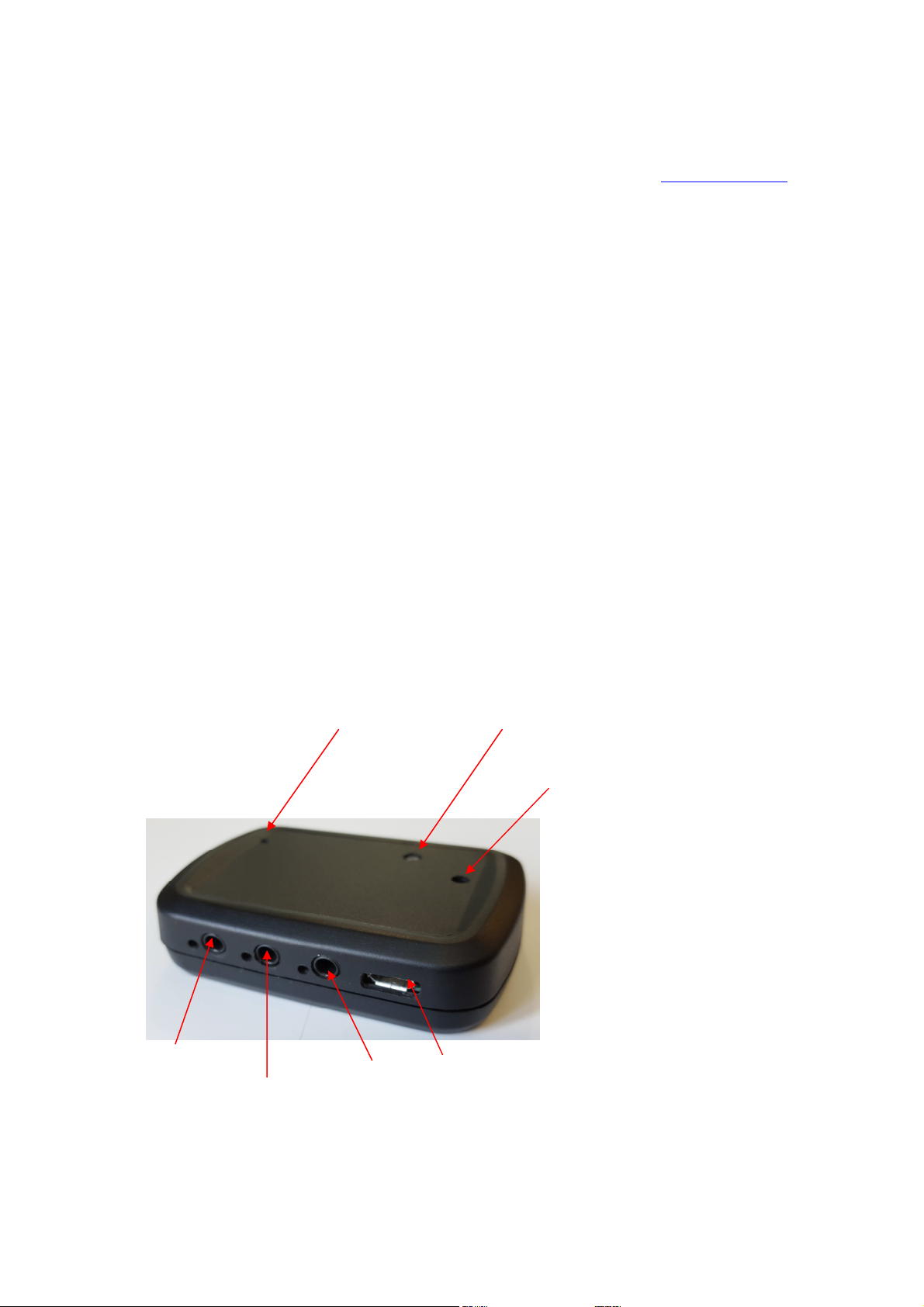
IR Senders/Blasters
The wIR-3 has 3 independent 3.5mm IR port for connecting IR flashers and IR Blaster, to the left of each
connector is an RED LED indicator. The RED LED indicator will flash while codes are being sent to the
port.
IR Port 3
IR port 2
Blue LED
IR port 1
Setup/Reset Button
Power Input
IR Learn
Port
Page 9

iRule setup
Command
received from Client
Acknowledgment
back to Client
s
endir<data>
↵↵↵↵
completeir,1:
2
,<sequence Number>
↵↵↵↵
After setup of the wIR-3 Gateway on your network, you can configure iRule by going into Gateways
setup in iRule and selecting Itach IR type gateway, enter a name for the gateway and the IP address that
you assigned to the wIR-3. Assign what device you want to use on each IR channel. For more detailed
instructions, reference iRule support on setting up Gateways.
Simple Control (roomie) setup
After setup of the wIR-3 Gateway on your network, you can configure Simple Control by going into Add
Devices and under Local Network Devices the wIR-3 will automatically show up as Global Cache
iTachWF2IR if the wIR-3 is setup to emulate Global Cache devices (see select The “Emulation mode”
under WiFi Setup). This may take up to 30 seconds to show up in Simple Control. Once the wIR-3 shows
up as a Global Cache unit, select the device and configure what IR port goes to what device. For more
detailed instructions, reference Simple Control support on Adding Device/ Gateways.
IR Gateway Commands
The wIR-3 Gateway receives/send commands to and from TCP port 4998 from the connected client. Up
to 5 clients can be connected at any one time. Acknowledgements will be sent to the Client that sent
the command. The table below list out all commands supported. The
carriage return hex OD.
↵↵↵↵
at the end of the commands = a
Send IR codes to the selected connector
sendir,1:2,571,37000,1,1,341,171,21,64,21,64,21,21,
21,21,21,21,21,21,21,21,21,64,21,64,21,21,21,64,21,
21,21,21,21,21,21,64,21,21,21,64,21,64,21,64,21,21,
21,21,21,21,21,64,21,21,21,21,21,21,21,21,21,64,21,
64,21,64,21,21,21,64,21,1600,341,85,21,3700
or GC Compressed format
sendir,1:2,571,37000,1,1,341,171,21,64B,21,21CCCC
BBCBCCCBCBBBCCCBCCCCBBBCB,21,1600,341,85,21,
3700
sendir {command}
,1 {module number}
:2 {IR Connector}
,571 {Sequence Number}
,37000 {IR Frequency}
,1 {Repeat Count}
,1 {Repeat from position}
After completion of sending the IR command to
the selected connector, the unit will respond
with the completeir command. The sequence
number is returned.
Page 10

,341 {First MARK}
,171 {First SPACE}
getversion
↵↵↵↵
version,
0
,{version}
↵↵↵↵
getdevices
↵↵↵↵
devices
,0,1
.WIFI
↵↵↵↵
↵↵↵↵
↵↵↵↵
ge
t_NET,0:1
↵↵↵↵
NET,0:1,<configlock>,<ipsettings>,<ipaddress>,
↵↵↵↵
g
et_IRL
↵↵↵↵
IR Learner Enabled
↵↵↵↵
stop_IRL
↵↵↵↵
IR Learner Disabled
↵↵↵↵
s
topir1:
<X>
↵↵↵↵
stopir1:<X>
↵↵↵↵
g
et_IR
1:<X>
↵↵↵↵
IR
1:<X><IR_BLASTER>
↵↵↵↵
Will send back the version of the wIR-3
Gateway’s firmware
Will send back connected devices for the
Gateway
Sends back the current network settings
Enable internal IR learning mode
Disable internal IR learning mode
{version} = 20170105V1.01
devices,1,3.IR
enddevices
<subnetmask>,<gateway>
<configlock> = LOCKED or UNLOCKED
<ipsettings> = DCHP or STATIC
<ipaddress> = IP Address
<subnetmask> = Subnet Mask
<gateway> = Gateway
After enabled the unit will send any learned codes in
Global Cache format to the client listening on TCP
port 4998
Disable internal IR learning
<X> Selected IR connector
Cancel repeating on any IR command that is
currently sending
<X> Selected IR connector
Sends IR port setting
<X> Selected IR connector
<X> Selected IR connector
Page 11

IR Leaner
From the units main web page select the button. This will enable the built in IR
receiver allowing the unit to Learn IR codes from your Remote Control. Point your remote control
emitter LED approximately 1/2” away from the hole on the top of the case opposite the BLUE blinking
LED. Press the desired button on your remote to learn the IR codes. When pressing buttons for
learning, only press the button for a moment, like you normally would, holding buttons for to long of a
time will create un-necessarily long IR codes sequence. The Blue LED will flash at the same rate of the
learned codes from your remote. Practice learning to get a better understanding of how the remote and
learning modes work. All learned codes are displayed in Global Cache format in the red window.
IR Learn
Receiving Port
Page 12
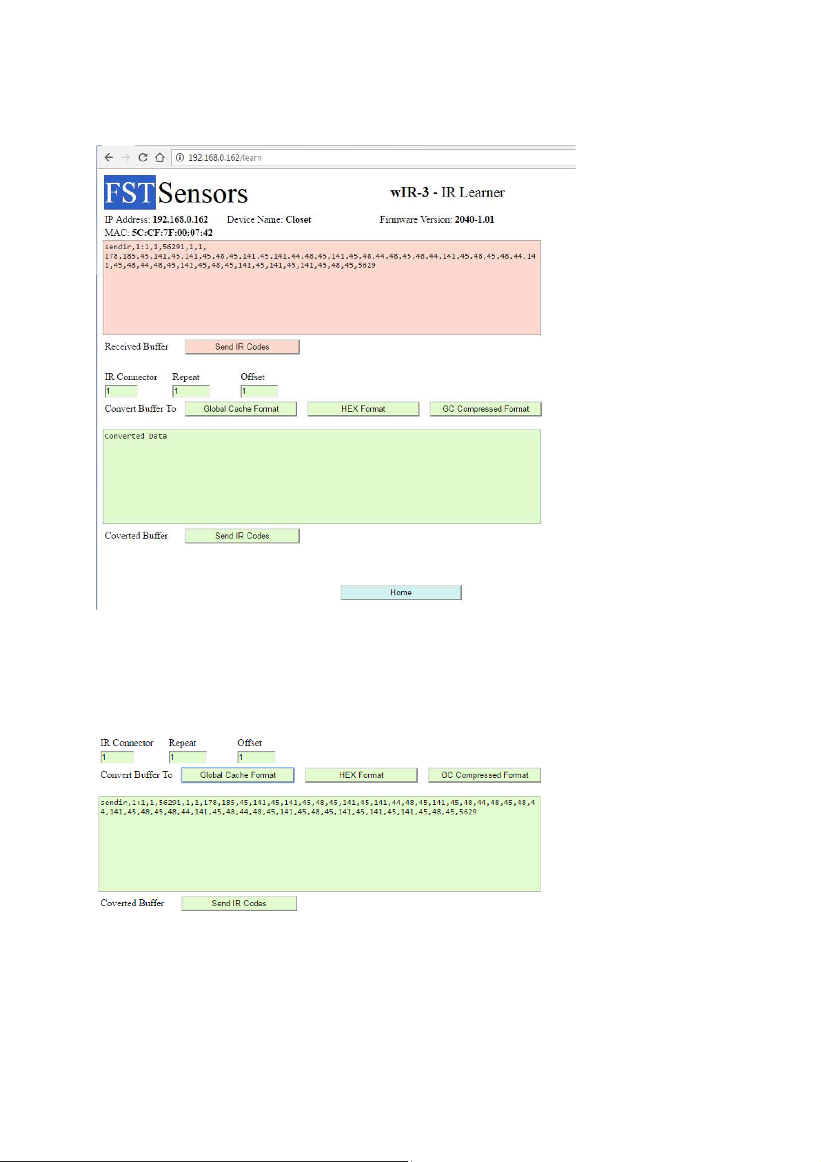
After you have learned the IR code from your remote, you can convert it to a different format like
Pronto HEX, simple hit the Pronto HEX button and the converted format will be displayed in the bottom
green window.
If you desire you can change the IR connector, the repeat and Offset by selecting the desired parameter.
Page 13
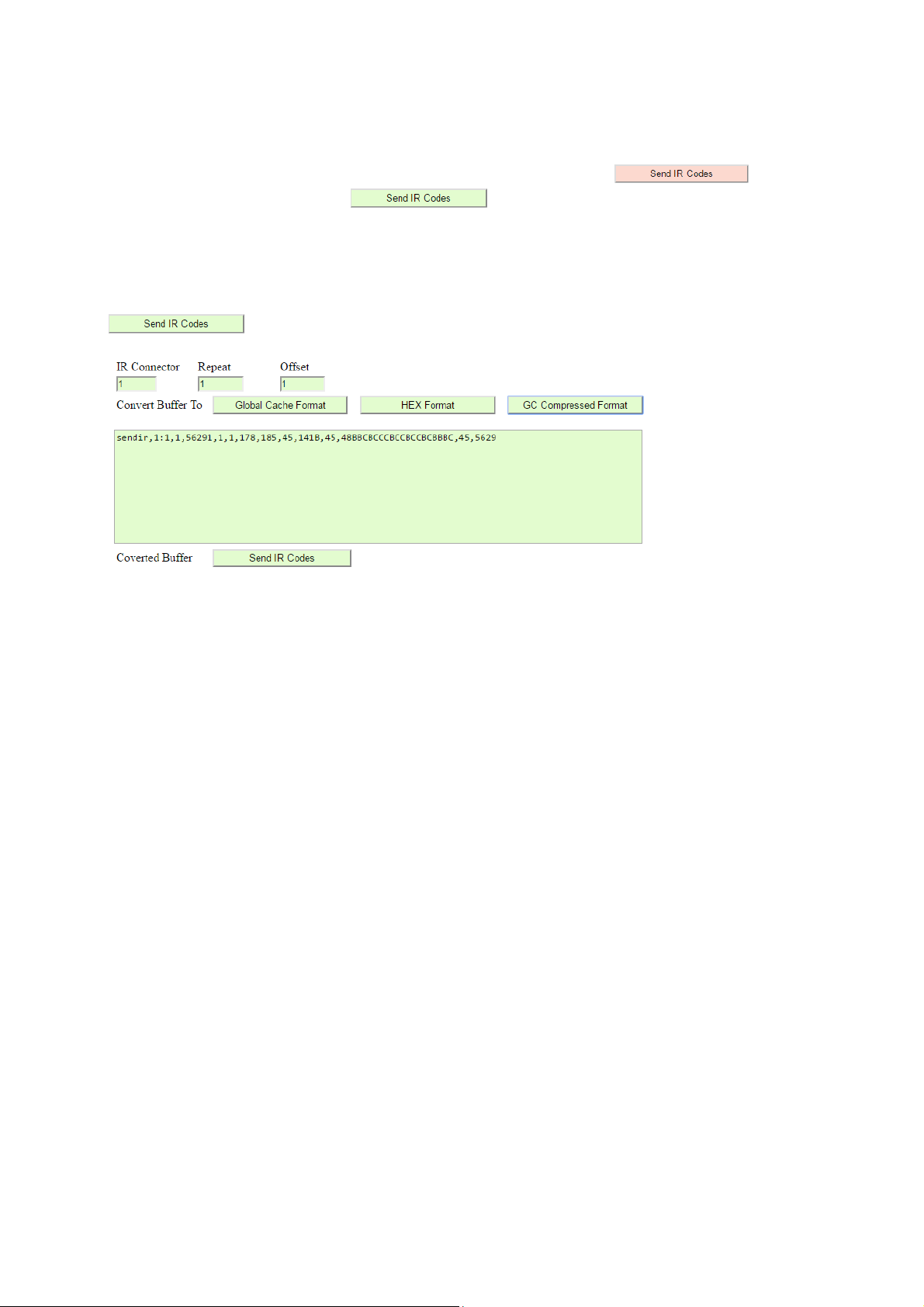
You can use one of the 2 IR Send buttons to test the learned IR codes. The will send
the codes in Receive buffer and the will send the codes in the Converted buffer. The
IR codes will be sent to the IR connector that is defined in the send string.
Example:
The below sample will send the converted buffer in GC Compressed format to IR connector 2 when the
is pressed.
IR Format breakdown
The below example has the breakdown of the format for the sendir command using the sample below.
sendir,1:2,1,56266,1,1,179,185,44,141,45,141,45,48,44,141,45,141,44,48,45,141,45,48,45,48,45,48,44,1
41,45,48,44,48,45,141,44,48,44,48,45,141,44,48,45,141,44,141,45,141,44,48,45,5626
sendir, {Send IR Command}
,1 {Module Number}
:2 {IR Connector to send to}
,1 {Sequence Number, 1 to 65535}
,56266 {IR Frequency}
,1 {Repeat IR Codes x times}
,1 {Start Repeating from x position, Must start on MARKS, will always be an odd number}
,179 {First MARK}
,185 {First SPACE}
,44 {Second MARK}
,141 {Second SPACE}
The MARK/SPACES continue to the last position which is always a SPACE
,5626 {The last position is the last SPACE}
Page 14
You can copy the codes out of the IR Learner page and paste them into your controlling device for
sending to your IR Gateway.
There are plenty of websites that have libraries of learned codes that you can use without having to
learn them.
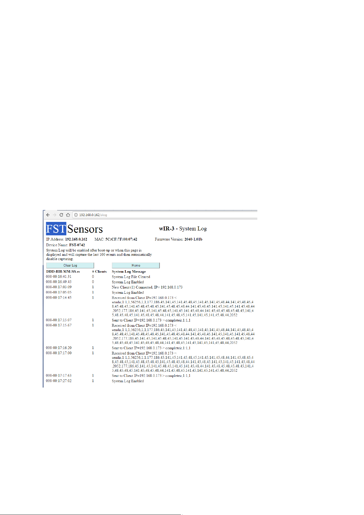
System Log
The wIR-3 can log of system events like connection to Wi-Fi, boot-up, client connections and message
received and sent to and from the clients. The system log will keep track of the last 100 system
messages upon entry to the System Log web page. The System Log will stop recording messages after
100 have been logged. The System log will time stamp each entry in Days, Hours, Minute, Seconds and
hundredths of second from the last boot up. The System Log will clear itself after the log size reaches
30,000 characters. Each time you select the display System Log from the main page the System Logging
will restart and collect the next 100 messages.
Page 15
Firmware Update
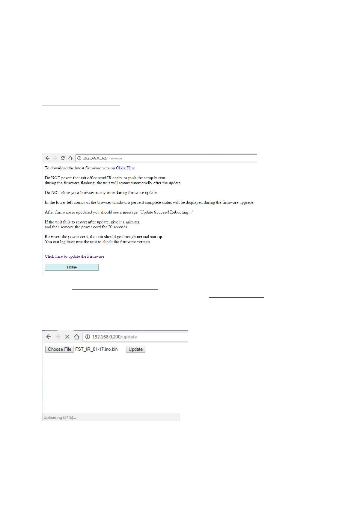
The W-IR3 firmware can be updated remotely via a web browser from the main page. Note: you can
update the firmware in AP mode also. Download the latest firmware file from
www.fstsensors.com/support or hit Click Here on the web page and it will direct you to
www.fstsensors.com/support in a new browser window.
NOTE: For your security, only load firmware files from FST Sensors web site. Loading firmware files
from other sites could introduce programs to breach your network and other connected devices on
your network.
Select the “Click here to select Firmware File” if you want to proceed with the firmware update
otherwise hit the home button. Chose the file you loaded from www.fstSensors.com and hit the Update
button. The progress percentage is displayed on the bottom left corner for the web page.
Page 16

The unit will be updated in less than a minute with the new firmware and reboot automatically. You
should see the message below after the firmware is updated.
Note: In most cases the current user settings will remain in effect based on the actual updates in the
firmware. Please check what features were added and if user settings will be affected.
 Loading...