

Page 1
Operating Manual
Adsorption Dryer
DTS 45-1100
Version: 11/2012/EN
Page 2

©
FST GmbH
16.03.2017
DMN-Betriebsanleitung FST DTS
-
V Standard MASTER
-EN-
20121105
-
CR.docx
Page 3

Table of contents
1. General information ........................................................................................................................................ 5
1.1 Manufacturer........................................................................................................................................... 5
1.2 Dryer data ................................................................................................................................................ 6
1.3 Contact data ............................................................................................................................................ 6
1.4 Additional documents ............................................................................................................................. 6
1.5 Warranty notes ........................................................................................................................................ 7
1.6 About this operating manual ................................................................................................................... 7
2. Description of application ............................................................................................................................... 9
2.1 Intended use ............................................................................................................................................ 9
2.2 Technical data ........................................................................................................................................ 11
3. Safety notes ................................................................................................................................................... 13
3.1 Signs and instructions ............................................................................................................................ 13
3.2 Danger zones at the dryer ..................................................................................................................... 14
3.3 General safety notes .............................................................................................................................. 15
4. Technical product description ....................................................................................................................... 17
4.1 Assembly drawing .................................................................................................................................. 17
4.2 Process flow diagram ............................................................................................................................. 19
4.3 Function description .............................................................................................................................. 20
4.4 Options .................................................................................................................................................. 24
5. Operating elements ....................................................................................................................................... 26
5.1 Main circuit breaker .............................................................................................................................. 26
5.2 Release button for temperature limiter ................................................................................................ 26
5.3 Pressure gauge ...................................................................................................................................... 27
5.4 Valve position indications ...................................................................................................................... 27
5.5 Instrument air supply and pilot valve terminal ..................................................................................... 28
5.6 Touch panel ........................................................................................................................................... 30
5.6.1 Overview of the operating elements ............................................................................................. 30
5.6.2 Starting and stopping the dryer control system ............................................................................ 31
5.6.3 Menu window: "alarm message" .................................................................................................. 33
5.6.4 Menu window: "info" .................................................................................................................... 34
5.6.5 Menu window: "process parameters"........................................................................................... 35
5.6.6 Menu window: "status" ................................................................................................................. 35
5.6.7 Menu window: "service" ............................................................................................................... 35
5.6.8 Menu window: "parameter" ......................................................................................................... 36
5.6.9 Menu window: "operation message" ............................................................................................ 41
5.6.10 Menu window: "system" ............................................................................................................... 41
5.6.11 Menu window: "password management" ..................................................................................... 42
5.7 Operation in the "operator" password level ......................................................................................... 43
5.7.1 Login .............................................................................................................................................. 43
5.7.2 Time control and dew point control .............................................................................................. 44
5.7.3 Setting the dew point limit value .................................................................................................. 45
5.7.4 Download of data logging history .................................................................................................. 46
5.7.5 Starting and stopping the dryer locally or remotely ..................................................................... 47
5.8 Control system interfaces ...................................................................................................................... 47
Page 4

Table of contents
5.9 Error messages and measures .............................................................................................................. 48
5.9.1 Error messages: alarms ................................................................................................................. 48
5.9.2 Error messages: warnings ............................................................................................................. 51
6. Transportation, setting up and storage ........................................................................................................ 54
6.1 Transportation ...................................................................................................................................... 54
6.2 Setting up .............................................................................................................................................. 55
6.3 Storage .................................................................................................................................................. 56
7. Installation .................................................................................................................................................... 57
7.1 Installing the connecting pipelines ....................................................................................................... 57
7.2 Installing the power supply .................................................................................................................. 60
8. Commissioning.............................................................................................................................................. 61
8.1 Requirements for initial commissioning ............................................................................................... 61
8.2 Starting the dryer .................................................................................................................................. 63
8.2.1 Pressurisation of the dryer ........................................................................................................... 64
8.2.2 Opening the outlet valve .............................................................................................................. 64
8.2.3 Checking the direction of rotation of the blower ......................................................................... 65
8.2.4 Correcting the direction of rotation of the blower ...................................................................... 66
8.2.5 Starting the dryer program ........................................................................................................... 66
9. Shutting down and restarting the dryer ....................................................................................................... 67
9.1 Shutting down the dryer in case of emergency .................................................................................... 67
9.2 Stopping the dryer ................................................................................................................................ 67
9.3 Shutting down the dryer ....................................................................................................................... 67
9.4 Depressurising the dryer ...................................................................................................................... 68
9.5 Restarting the dryer .............................................................................................................................. 68
10. Maintenance and repair ............................................................................................................................... 69
10.1 Regular maintenance intervals ............................................................................................................. 70
10.1.1 Visual check and function monitoring .......................................................................................... 71
10.1.2 Cleaning the protection grid ......................................................................................................... 71
10.1.3 Cleaning the dryer and dryer control system ............................................................................... 71
10.1.4 Checking if cable and terminals are securely fixed....................................................................... 71
10.1.5 Calibrating the dew point sensor.................................................................................................. 72
10.1.6 Replacing filter elements .............................................................................................................. 73
10.1.7 Replacing the pilot valves ............................................................................................................. 73
10.1.8 Replacing the expansion silencer ................................................................................................. 74
10.1.9 Checking the blower shaft bearing ............................................................................................... 74
10.1.10 Replace seals and seat kit of angle seat valves............................................................................. 74
10.1.11 Checking and replacing the desiccant / cleaning the strainer basket .......................................... 75
10.1.12 Replacing the rubber valve seat and the non-return valve .......................................................... 77
11. Appendix and technical documents ............................................................................................................. 78
11.1 Declaration of Conformity .................................................................................................................... 78
11.2 General arrangement drawing ............................................................................................................. 79
11.3 Process flow diagram ............................................................................................................................ 79
11.4 Pneumatic diagram ............................................................................................................................... 79
11.5 Wiring diagram ..................................................................................................................................... 79
Page 5
1. General information
1.1 Manufacturer
FST GmbH
Head office: Weiherdamm 17 – 57250 Netphen, Germany
General information
Sales office: Im Teelbruch 106 – 45219 Essen, Germany
℡ +49 (0) 2054 8735-0
+49 (0) 2054 8735-100
! For any questions about the product, please contact the sales office !
In case of questions about the product, please specify the type and the manufacturing number. This
information can be found on the type plate on the control box of the dryer. (→ Page 13)
5
Page 6

General information
1.2 Dryer data
Model:
Order no.:
Manufacturing no.:
Vessel no. (left/right):
Year of manufacture:
Date of commissioning:
1.3 Contact data
Name:
Company:
Address:
Phone / Fax:
E-mail:
The above dryer data differs for each dryer. Please fill in the fields according to the type plate and your contract documents. This data enables the manufacturer to clearly identify the dryer and simplifies service and
provision of the proper spare parts.
Some of the information listed here and other important data can be found on the type plate of the dryer and
on the type plate of the vessels. (→ Page 13)
1.4 Additional documents
General arrangement drawing
Process flow diagram
Pneumatic diagram of the instrument air for valve actuators
Wiring diagram
Note on additional documents
Additional documents (e.g. of the components) must be adhered to. They contain additional information, e.g.
on maintenance, and are therefore necessary for safe operation of the dryer.
The customer is provided with pressure vessel documents, if applicable.
6
Page 7

General information
1.5 Warranty notes
For warranty information, please refer to our "General Terms of Sale and Delivery".
(→ www.fstweb.de)
In the following cases the warranty shall be void:
If the safety notes and instructions of this operating manual and of the additional documents are not
observed.
If the dryer is operated or maintained by personnel who do not have the required qualifications. (→
see "Target group": (→ Page 7)
If the dryer is used for anything other than its intended use. (→ Page 9)
If aggressive substances in the compressed air or ambient air cause damage to the dryer.
If parts other than genuine parts of the manufacturer have been used for maintenance and repair.
If the dryer is operated although defects are evident.
1.6 About this operating manual
This operating manual contains all the technical information required for installation, operation, maintenance
and disposal of the dryer.
Target group
This operating manual is directed to all persons working on and with the dryer. We point out that these persons have to be qualified personnel who, because auf their qualification and experience, are familiar with handling compressed air systems and electrical systems. If you are not experienced in using these systems, please
ask the relevant experts for help. We highly recommend that commissioning and maintenance be carried out
by the manufacturer or one of the authorised service partners.
Using the operating manual
Please read the operating manual and the additional documents carefully prior to installation and follow the
notes and instructions. Safe and proper operation of the dryer can only be guaranteed if the instructions and
notes are observed. The safety notes must be observed in particular.
The operating manual must be kept in the vicinity of the dryer and must be easily accessible.
When selling or hiring out the dryer, also provide this operating manual and all the additional documents to
the new user. (→ Page 6)
The manufacturer accepts no liability for damages resulting from disregard of the operating manual.
All the information in this operating manual is valid at the time the manual is published. Due to component or
workflow modifications at any time affecting dryer maintenance, the latest information should be available
prior to maintenance work.
7
Page 8
General information
CAUTION
!
WARNING !
DANGER !
Note!
Tips and hints!
Signs and symbols used
Boxes are used for bulleted lists.
1) Enumerated lists point out that the working steps are to be carried out in a specified order.
→ Cross references refer to information on a different page or in a different document.
This symbol refers to matters that should be given special attention.
Observing the notes helps to ensure safe handling of the product.
This symbol refers to matters that should be given special attention.
Observing these advisory notes helps to ensure particular efficient operation of the product.
This symbol indicates a possible harmful situation.
When not avoiding this situation, there is a danger of injury or damage to the product or to adjacent system components.
This symbol indicates a possible dangerous situation.
When not avoiding this situation, there is a danger of serious injury or death.
This symbol indicates an immediate impending danger.
Not avoiding this danger results in serious injury or death.
8
Page 9

Description of application
2. Description of application
The dryer is used to remove moisture from compressed air for industrial use.
Typically, the dryer is used for drying compressed air from a compressor station.
During pre-treatment of the compressed air by means of separators and fine filters only the liquid water components can be removed from the compressed air. After this pre-treatment the dryer also removes the vaporous water components. The compressed air is dried until only a very low residual concentration of water vapour remains in the dried compressed air. This residual moisture content is measured as the pressure dew
point in °C.
The dryer works completely automatically and is designed for continuous operation. Thanks to numerous
communication interfaces and an optionally available moisture measuring system the dryer can be operated
very economically.
2.1 Intended use
The dryer is exclusively designed for drying compressed air!
Using the dryer for drying other gases (e.g. pure nitrogen) must be agreed on with the manufacturer. It may be
necessary to observe special safety directives.
The dryer is designed to be set up at a site that complies with the following requirements:
Indoors
Protected against weather impact
Ventilated
Frost-free
Dry
Zero to minimum dust-laden ambient air
No vibration via floor or connected piping
Ambient air must be free from aggressive and corrosive substances
Ambient air must be free from substances that damage the desiccant or influence its effectiveness
(e.g. ammonia or other alkaline-reacting substances, oil mist, water spray or drizzle)
Free from dangers due to explosive atmospheres inside and outside the dryer. (The standard dryer
version does not comply with ATEX.)
The dryer must only be operated with compressed air within the maximum allowable operating conditions.
The voltage supply must correspond to the specified values.
The maximum allowable operating conditions and the required voltage supply are specified on the type plate
(→ page 13).
Modifications to the dryer or use of third-party parts may cause unpredictable danger and damage. These
measures must only be carried out after previous check and approval of the manufacturer. Only use genuine
spare parts of the manufacturer.
9
Page 10

Description of application
In the event
of pre
-
dried compressed air
Any other use is considered improper and therefore not permissible. The manufacturer accepts no liability
caused by improper use.
The values specified on the type plate are mechanical design limits.
Please note that dryer performance is not defined to these mechanical design limits. Dryer performance is
guaranteed for use under the "nominal operating conditions" as well as for a certain combination of the individual operating parameters, that has been established for this dryer in the planning phase (compressed air
flow rate, pressure, temperature, desired pressure dew point, ambient temperature and ambient humidity).
For the nominal operating conditions please refer to the following table. (
For a dryer designed to your individual operating conditions, please refer to your contract documents or contact the manufacturer.
Dryer performance cannot be guaranteed if the dryer is not operated within these operating conditions.
The supplied compressed air must be of the following quality:
Free from aggressive and corrosive substances
Filtered acc. to ISO 8573-1:2010 (1:*:3)
Free from substances damaging the desiccant
*= The compressed air should be saturated with moisture or only be slightly subsaturated. When using predried compressed air (e.g. downstream of a fridge dryer) the dryer performance may be reduced.
During initial commissioning and after desiccant replacement in particular, pre-dried compressed air may negatively affect dryer performance.
For some days, operate the dryer using moisture-saturated compressed air in order to activate the
desiccant. For this activation process the dryer control system should be set as follows:
1) Select the "variable" cycle mode. (→ Page 40)
2) Select a dew point limit value that can still be tolerated, however, it must not be worse than
-10°C. (→ page 45)
The dew point should become better within the next days.
3) Monitor the development of the dew point measured value for some days.
4) Select a dew point limit value that is approximately 10°C worse than the dew point that is
usually reached, however, it must not be worse than -10°C.
Usually, dryer performance will be adequate after this procedure even when using pre-dried compressed air. If the dew point becomes worse again at a later point in time, the procedure must be
repeated.
→ Page 11)
Example:
The dryer is to be reaching a dew point of -40°C. However, in most cases it only reaches -30°C.
Select the "variable" cycle mode and then a dew point limit value of -20°C.
The adsorption phases of the dryer are now very long and thus the dryer is increasingly laden with moisture.
After some days the dew point becomes better and reaches values around -55°C.
Now, select a dew point limit value of -40°C. The dryer should now permanently be reaching good dew points.
10
Page 11

410
530 2225
1190
1000
500
560 2225
1190
1000
645
740 2325
1310
1085
790
790 2325
1310
1085
1210
1150
2705
1460
1150
1490
1350
2720
1510
1230
2100
1650
2770
1600
1460
2440
1800
2885
2015
1475
2950
2400
2920
2045
1505
3750
2850
2970
2160
1590
4250
3900
3210
2370
1560
4930
4050
3235
2475
1745
5330
4250
3250
2520
1870
6510
5000
3520
2520
1920
7180
5650
3560
2640
1985
8600
6400
3590
4400
1995
9400
7500
3610
4500
1995
11000
8750
3650
4750
1995
Classification acc. to PED 97/23/EG
IV
Fluid group
2
Supply voltage
400 V, 50 Hz
Class of protection
IP54
Min. / max. allowable pressure (PS)
4 bar to 11 bar
(an ex
ternal instrument air
Min. / max. allowable temperature (TS)
+1°C to +50°C
at the
dryer inlet
Allowable pressure loss in the exhaust air duct
20 mbar
Appropriate ambient air quality for regeneration
Dust contents < 50 mg/m³
Noise pressure level (free
-
field measurement in distance
75 dB(A) to 90 dB(A)
2.2 Technical data
Description of application
Dryer
DTS 45 V
DTS 55 V
DTS 65 V
DTS 85 V
DTS 125 V
DTS 155 V
DTS 215 V
DTS 250 V
DTS 300 V
DTS 380 V
DTS 430 V
DTS 500 V
DTS 540 V
DTS 650 V
DTS 720 V
DTS 860 V
DTS 940 V
DTS 1100 V
Nominal vol-
ume flow rate
V [m³/h]*
Compressed air
DN 40
DN 40
DN 50
DN 50
DN 80
DN 80
DN 80
DN 100
DN 100
DN 100
DN 150
DN 150
DN 150
DN 150
DN 150
DN 200
DN 200
DN 200
connection
Weight
[kg] [mm] [mm] [mm] [kW]
Height
Width
Depth
Installed heater
power
4.5 0.85 130
4.5 0.85 130
8.0 1.60 220
8.0 1.60 220
11.0 2.20 270
14.0 4.00 350
18.0 4.00 525
28.0 8.50 840
28.0 8.50 840
35.0 8.50 840
40.0 8.50 1100
40.0 8.50 1100
58.0 15.00 1670
58.0 15.00 1670
69.0 15.00 1670
84.0 18.50 2304
84.0 18.50 2304
95.0 30.00 2595
Installed
motor power
Exhaust air flow
[kW] [m³/h]**
rate
* = Standardised to 1 bar(a) and 20°C as well as to the following operating conditions: 7 bar operating
overpressure, 35°C inlet temperature and -40°C pressure dew point
** = Standardised to 1 bar (a) and 20°C at atmospheric pressure
of 1 m)
supply is required for an operation pressure
below 5bar)
Temperature +1°C to 40°C
Absolute moisture < 14 g/m³
11
Page 12

Description of application
Individual operating conditions
Pressure vessel
Please contact the manufacturer when your operating conditions are not within the limits stated
above.
Options adapting the dryer to your operating conditions can be provided for numerous special
cases.
For further technical details on the pressure vessels, please refer to the pressure vessel documentation provided separately.
A routine inspection is required for the pressure vessels. In Germany, according to AD 2000 Code a
routine inspection has to be carried out every 5 years by a notified body.
Please note that different national regulations may apply in other countries.
12
Page 13
Safety notes
Note!
3. Safety notes
The dryer has been built according to state-of-the-art technology and recognised safety rules. However, there
is a risk of danger that every person working with the dryer must be aware of. In particular, improper handling
of compressed air and electricity may result in serious injury or death. If you are not experienced in using these
systems, please ask the relevant experts for help.
In order to prevent personal injury or damage, the safety notes must be observed when using
this dryer.
Observe the specific safety notes in the relevant chapters.
Observe the legal guidelines and the accident prevention regulations.
Observe the safety notes of the local site regulations.
3.1 Signs and instructions
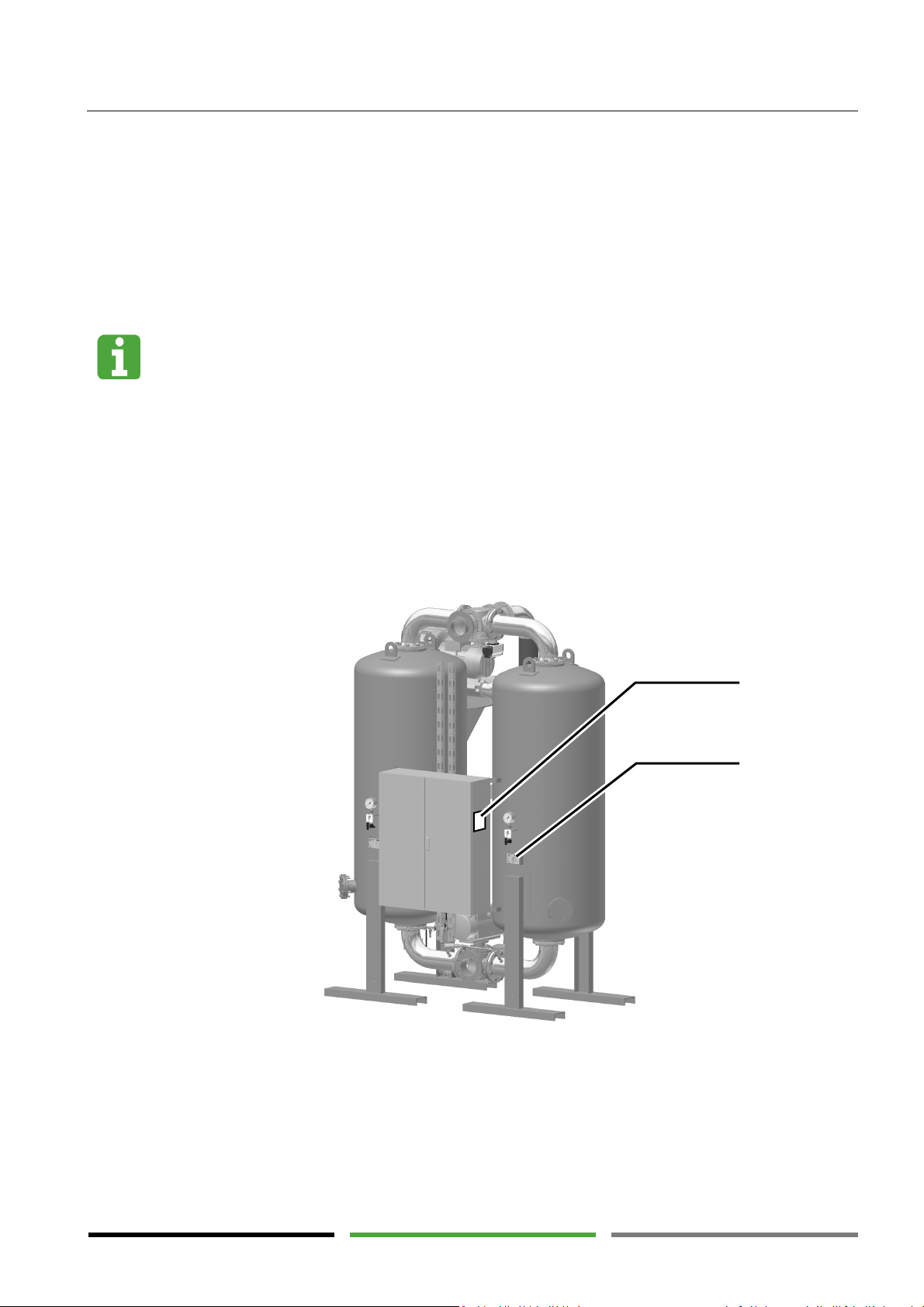
1
Type plate of the dryer
2
Type plate of the vessels
1
2
The type plates show important information. Make sure that the type plates are always clearly readable.
13
Page 14
Safety notes
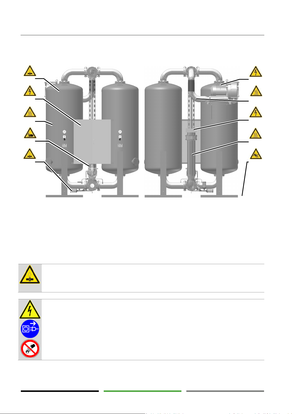
DANGER !
– Overpressure (1)
DANGER !
– Electric voltage (2;6;8)
1
2
4
5
3
3.2 Danger zones at the dryer
1
2;6;8
3;9
Risk of injury from pressure-bearing parts
Risk of injury from electric voltage
Risk of burns at hot vessel and piping
surfaces
4
Risk of crushing at cardan shaft during
valve movement
5
Risk of injury from suddenly escaping com-
pressed air
7
Risk of injury from hot exhaust air flow
10
Risk of slipping due to spilt desiccant
6
7
8
9
10
The dryer is under pressure.
Suddenly escaping compressed air may result in serious injury.
Do not carry out mechanical or electrical work on the dryer as long as the dryer is under pressure.
The dryer is operated electric voltages up to 690 V.
Touching live parts may result in serious injury or death.
Work on electrical components must only be carried out by qualified and authorised personnel.
Use a voltage detector to make sure the dryer has been disconnected from the power supply and
that there are no live parts before starting maintenance work.
In the event of fire, do not extinguish the fire using water.
14
Page 15
Safety notes
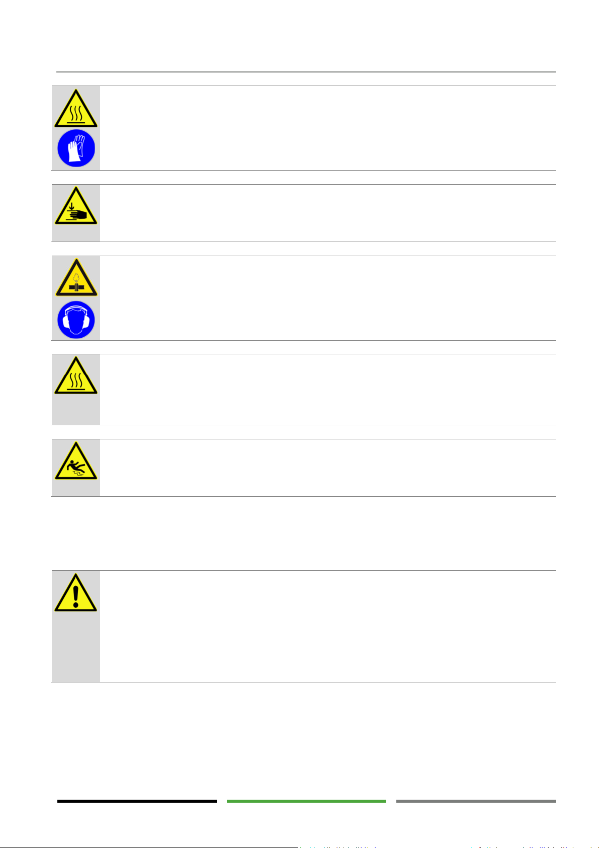
WARNING !
– Hot surfaces (3;9)
WARNING !
– Risk of crushing (4)
WARNING !
–
Suddenly escaping compressed air (5)
CAUTION !
Hot
exhaust air flow (7)
WARNING !
– Risk of slipping (10)
DANGER !
–
Overload
The surfaces of the vessels and pipes may reach temperatures above 150°C.
Unprotected touching of this surface may cause burns.
Avoid direct contact to these surfaces. Restrict access to the surfaces, if necessary, or install thermal insulation on the hot components. (→ Page 24)
Never store inflammable parts and material in the vicinity of the dryer.
The cardan shaft will automatically turn by 90° approximately every 6 hours. Touching the cardan
shaft may cause parts of the body to be injured or twisted.
Do not hold on to the cardan shaft. Do not put your hand into the link joint of the cardan shaft.
The dryer is depressurised approximately every 6 hours using a silencer. A loud and strong airstream may carry small particles and cause injury.
Do not place any equipment in the vicinity of the silencer. The silencer must not be manipulated or
removed. Always wear hearing protectors when working in the vicinity of the dryer.
–
Hot air escapes from the regeneration air outlet. The surface of the exhaust air duct may reach
temperatures above 150°C. Unprotected touching of this surface may cause burns.
The installation room temperature will rise when not using an exhaust air duct.
Install an exhaust air duct out of reach of persons.
After desiccant replacement some amounts of desiccant may still remain on the floor.
The desiccant is very slippery and may result in serious fall injury.
Immediately remove residual desiccant properly from the floor.
3.3 General safety notes
The dryer must only be operated with compressed air within the maximum allowable operating
conditions. The operating conditions are defined on the type plate (→ page 13).
Exceeding the maximum allowable operating conditions may result in serious injury or death.
It is the duty of the operator to ensure that the connected pressure source is safe-guarded such
that the maximum allowable operating pressure (PS) and the maximum allowable temperature
(TS) are not exceeded.
Please also refer to section "Intended use" (→ page 9).
15
Page 16
Safety notes
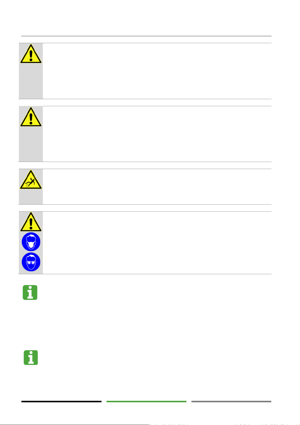
DANGER !
– Unauthorised modifications
DANGER
! –
Suspected misuse
WARNING !
– Risk of falls
CAUTION !
– Desiccant dust
Desiccant
Modifications to the dryer or the dryer control system may result in dangerous operating states.
Violations may cause serious injury or death.
Never modify the dryer function by means of conversions.
Never carry out welding work on pressure-bearing parts.
Never change the control program of the dryer.
Any modifications of the dryer must be agreed on with the manufacturer and confirmed in writing.
Using the dryer for unintended purposes may result in dangerous situations. Violations may cause
serious injury or death.
Never use the dryer as a climbing aid.
Never use the dryer as a support for external weight loads.
Never use dryer components for unintended application purposes.
Please also refer to section "Intended use" (→ page 9).
The dryer must never be used as a climbing aid. The dryer components will not provide adequate
support and parts of the dryer may break off. Disregard may lead to dryer damages and falls with
serious injuries.
When working at height only use approved climb assist systems.
Using the desiccant may lead to mineral dust formation.
Desiccant dust may cause eye and respiratory tract irritations.
Wear eye protection and a dust mask when handling the desiccant.
The desiccant used is not subject to labelling requirements according to the Hazardous Substances
Ordinance. Nevertheless, the common safety measures with regard to using chemicals apply.
The manufacturer will provide safety data sheets on request.
The desiccant may accumulate contaminants from the compressed air. Depending on the type of
contamination there may be a risk of injury or damage when using the desiccant. As the type of
contamination is not known to the manufacturer, the resulting risks cannot be evaluated in this
operating manual.
Additional safety notes
For additional safety notes, please refer to the relevant chapters.
16
Page 17
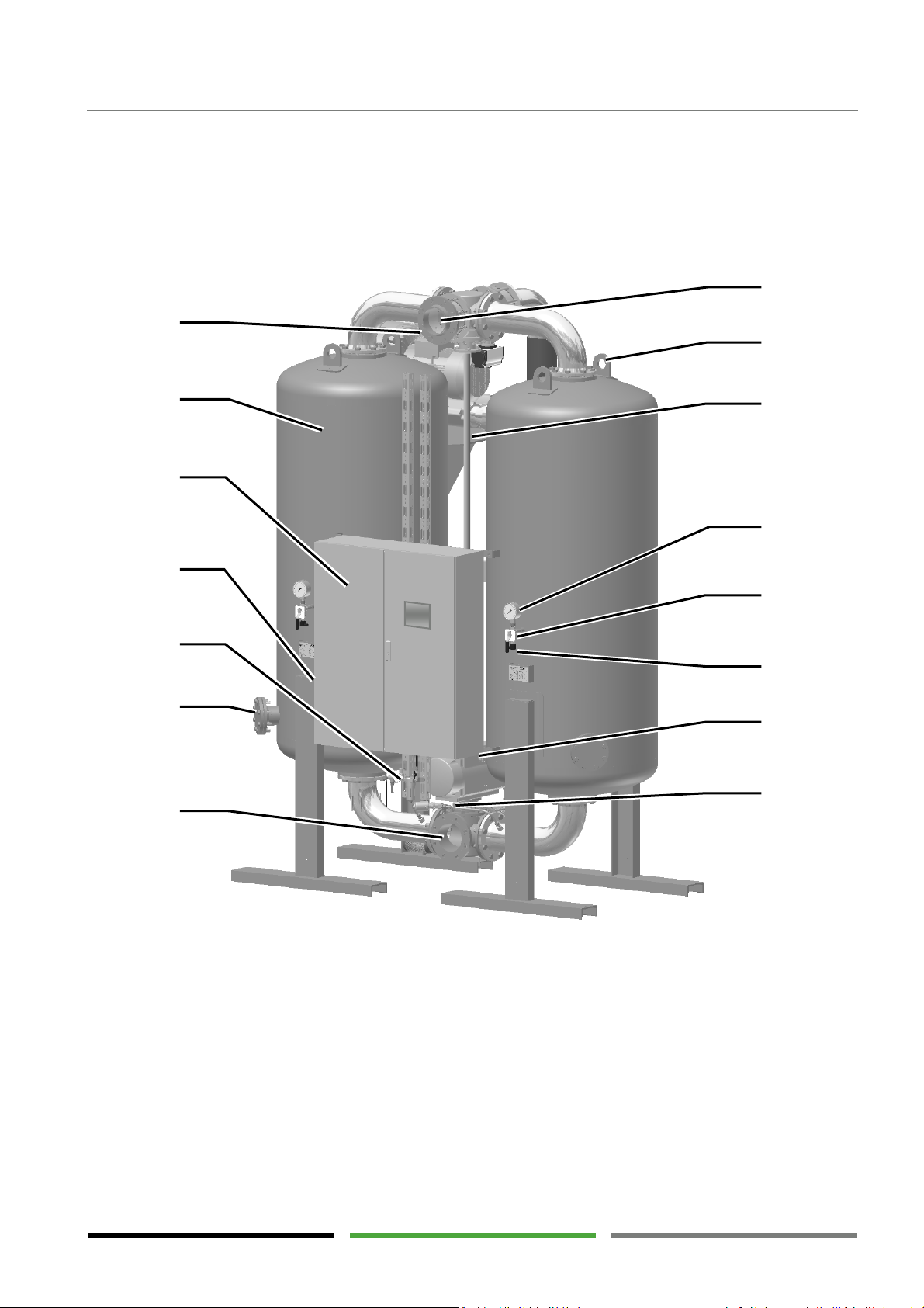
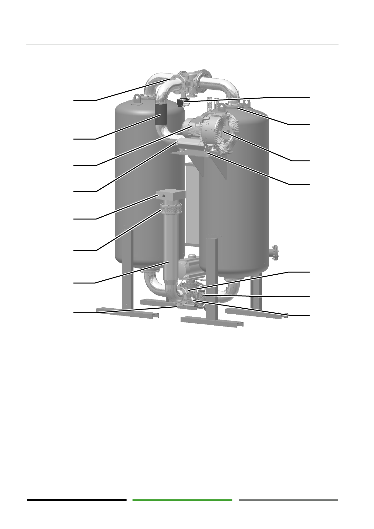
Compressed air inlet (GJ) /
Compressed air outlet (GO) /
Desiccant drain
Upper lifting lugs
Instrument air filter
Cardan shaft for connecting the main valves
Main
circuit breaker
Pressure gauge (PI01, PI02)
Control box with touch panel
Manual valve for pressure measurement
Vessel (A1, A2) with sieve tray (ST1, ST2)
Pressure sensor (PT01, PT01)
Dew point sensor (MT01) (*optional)
Limit switch (GS01) (*optional)
Pressurisation valve (V4)
5
1
2
7*
3
6
4
4. Technical product description
4.1 Assembly drawing
Front view
Technical product description
8
9
10
11
12
13
14*
15
1
lower main valve with actuator (V1)
2
3
4
5
6
7
8
upper main valve (V2)
9
10
11
12
(HV1, HV2)
13
14
15
17
Page 18
product description
Temperature sensor (TT01) for regeneration
Temperature sensor (TT02) for measuring
Heater (H1) inside flow tube
Regeneration air valve (V3)
Regeneration air intake (RJ) with protection
Upper
vessel opening with strainer basket
Heater junction box with release button for
Blower (M1)
Vibration absorber
Regeneration air outlet on the blower (RO)
Non-return valve (RV1)
Blower motor
with cooling fan (M1)
Expansion silencer (X1)
Flexible hose (P1)
Expansion valve (V5)
Rear view
Technical
24
23
22
21
20
19
18
17
17
gas temperature control
18
19
grid (SG1)
20
temperature limiter (TSH01)
25
26
27
28
29
30
31
24
the regeneration air outlet temperature
25
with limit switch (GS03)
26
(SB1, SB2)
27
28
21
22
23
18
29
30
31
Page 19
Technical product description
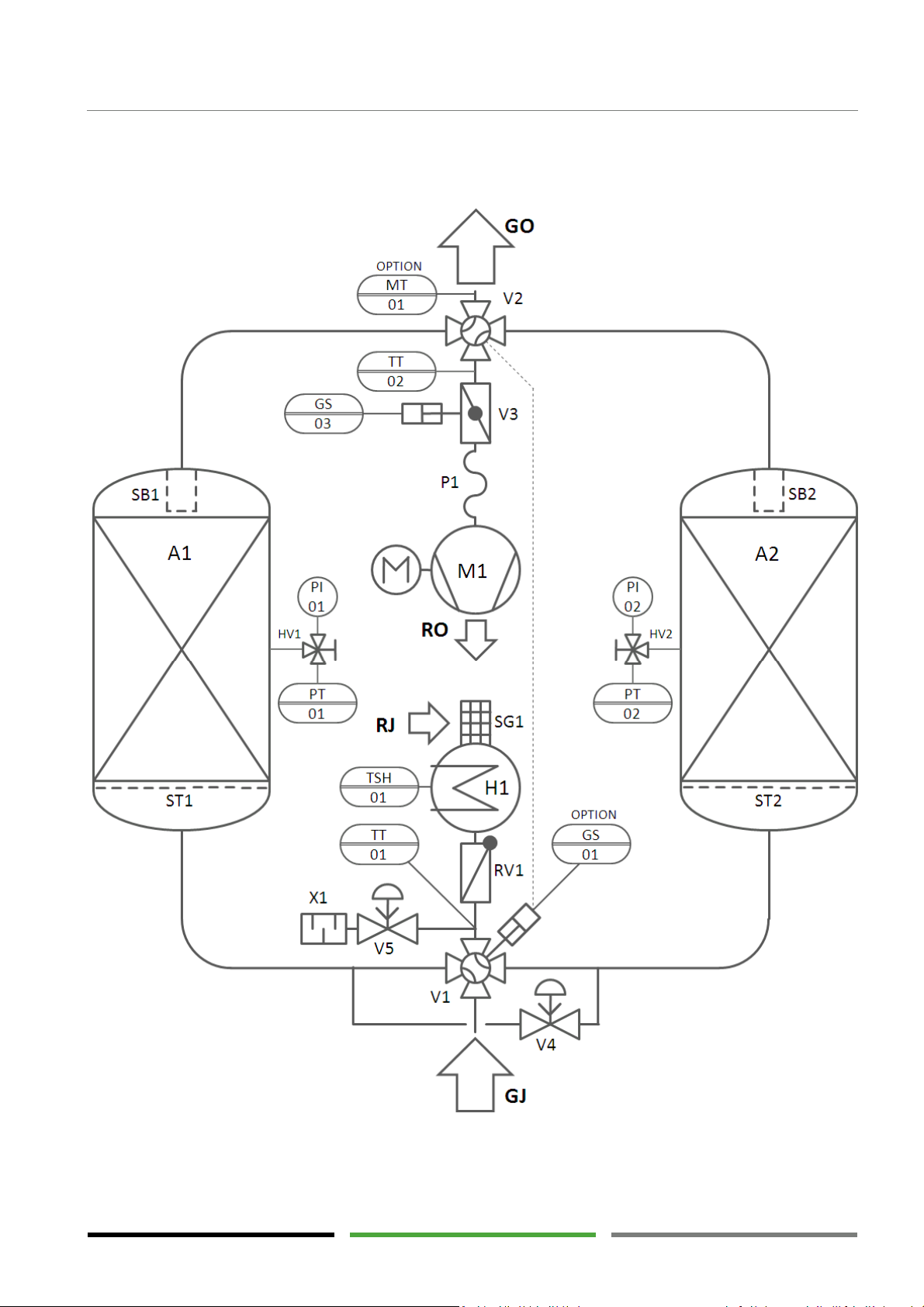
4.2 Process flow diagram
Symbolic diagram of the dryer components, their locations and interconnections.
19
Page 20
Technical
product description
4.3 Function description
The operation principle of the dryer is adsorption. The principle of moisture adsorption is water molecules
being attracted to a hygroscopic solid material (desiccant). This process is reversible and, after a regeneration
phase, the desiccant can be reused for drying.
For compressed air drying the compressed air flow is led through a vessel containing the desiccant and
brought into intensive contact with the desiccant. The desiccant removes moisture from the compressed air
and stores it in its internal structure. With continuous moisture loading of the desiccant the dryer performance
is reduced until the desiccant is saturated with moisture. The saturated desiccant then requires regeneration,
i.e. the moisture stored in the inner desiccant structure is removed again. The desiccant can then be reused for
drying.
Continuous operation of an adsorption dryer requires two vessels that are operated alternately. One vessel is
used for drying the compressed air (adsorption). In the other vessel the regeneration phases are carried out.
The change interval between adsorption and regeneration is 6 hours or longer.
Adsorption phase
Duration approx. 6 to 48 hours
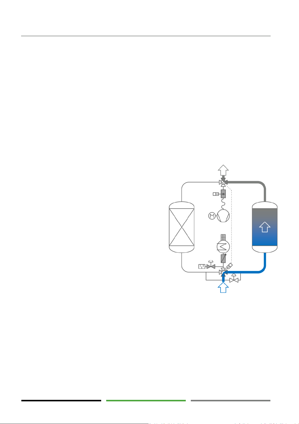
The moist compressed air is supplied from a compressed air
source (e.g. compressor) to the compressed air inlet (GJ) of the
dryer. The lower main valve (V1) forwards the compressed air
to the vessel which is in "adsorption" mode (here A2). In the
lower part of the vessel the compressed air is decelerated and
distributed over the vessel cross-section. The compressed air
passes the sieve tray (ST2) and slowly flows through the desiccant bed. The compressed air exits the vessel via the strainer
basket (SB2) and is forwarded from the upper main valve (V2)
to the compressed air outlet (GO).
The optional dew point sensor (MT01) checks the dryer performance at the compressed air outlet.
During this time the second vessel is in standby mode and
waits for operation.
The adsorption phase is completed and the vessels are switched over if...
"fixed" cycle mode has been pre-selected and a time of 6 hours has expired.
"variable" cycle mode has been pre-selected and optional dew point measurement has reached the
selected limit value. Switch-over of the vessels is carried out compulsorily after 48 hours at the latest.
1 standby - adsorption
20
Page 21
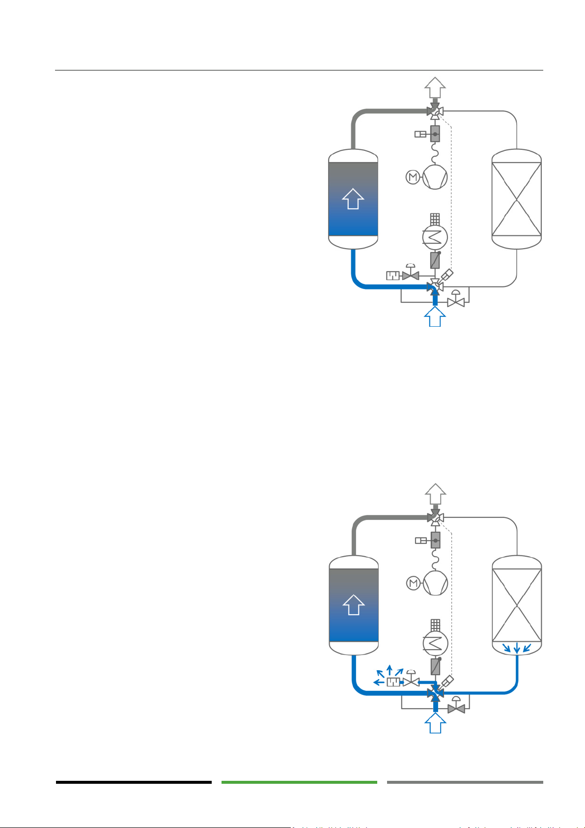
For vessel switch-over the main valves (V1) and (V2) are
switched synchronously using a common actuator. The
compressed air flows from one vessel to the other. A free
flow path through the dryer is available at any time during
switch-over. As a result, the task of drying is passed on to
the other vessel without interruption.
Now vessel (A2) has gone “offline” and vessel (A1) has
gone “online”.
Technical product description
Regeneration
Duration approx. 3 hours or longer
After the "wet" vessel (A2) has completed the adsorption
phase and passed on the task to the second vessel (A1), the
first vessel (offline vessel) runs the regeneration phases.
Regeneration is divided into the following phases:
Expansion
Heating
Cooling
Pressurisation
Standby
Expansion phase
Duration approx. 3 to 10 min
After vessel switch-over the expansion valve (V5) is opened
and the "wet" vessel is depressurised. Via the silencer (X1)
the compressed air flows to the outside.
The dryer control system monitors the vessel pressure
using the pressure sensor (PT02). The next phase begins
when the vessel pressure falls below the selected limit
value.
2 adsorption – switch-over
3 adsorption - expansion
21
Page 22
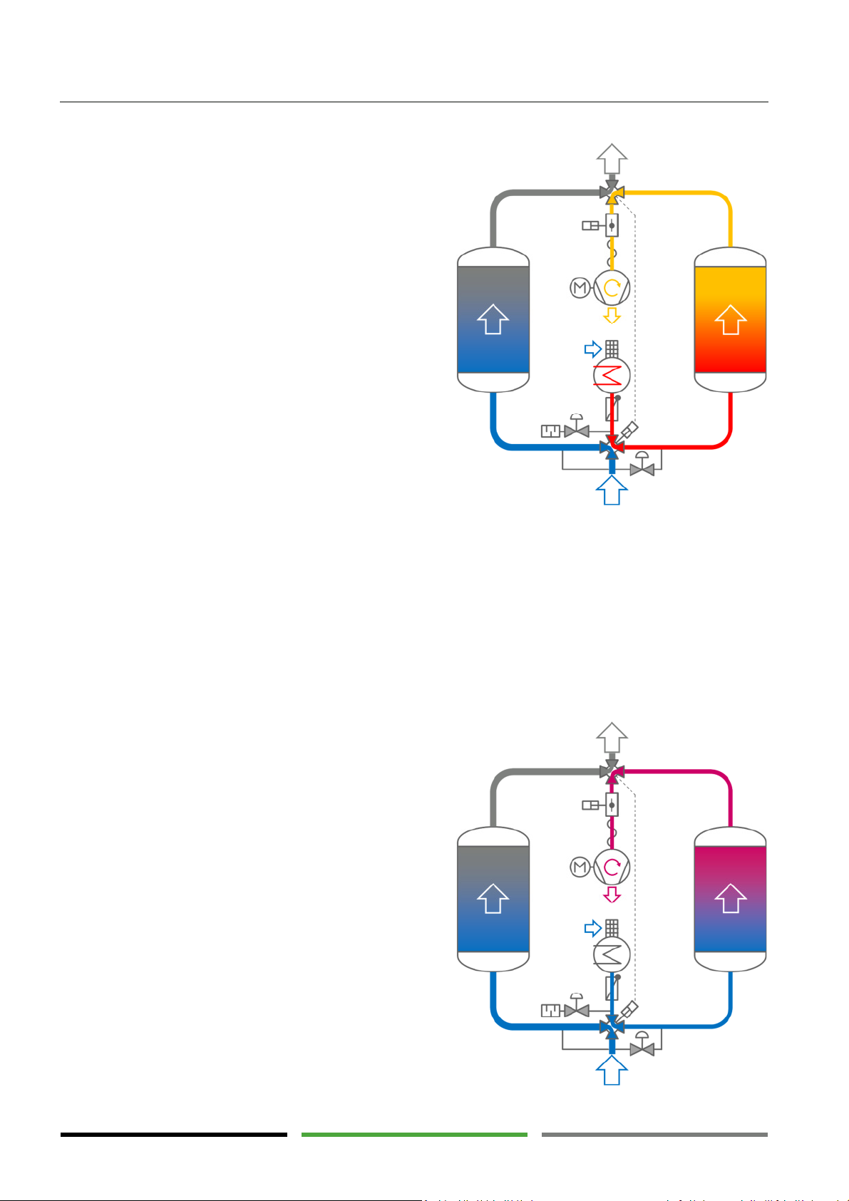
product description
4 a
dsorption
- heating
Heating phase
Duration approx. 2 hours or longer
After the vessel pressure has almost reached atmospheric
pressure, the regeneration air valve (V3) is opened, the
expansion valve (V5) is closed, the blower (M1) is started,
and the heater (H1) is switched on.
Ambient air is drawn in via the protection grid (SG1) and
heated up by the heater (H1) to approximately 140°C to
180°C. Via the temperature sensor (TT01) the dryer control
system controls the regeneration air temperature to maintain the selected value. The temperature limiter (TSH01)
protects the heater against overheating. When exceeding
the limit temperature set on the temperature limiter scale
it switches of the heater.
The hot regeneration air is distributed throughout the vessel cross-section and led through the desiccant. The heat in
the regeneration air vaporises the water stored in the desiccant. In the form of steam the water, together with the
regeneration air flow, is then led to the outside of the vessel. The warm, moist regeneration air flow is forwarded to
the regeneration air outlet (RO) via the blower (M1).
As soon as the hot regeneration air flow has vaporised the
water from the vessel, the temperature at the vessel outlet
starts to rise quickly. Using the temperature sensor (TT02)
the dryer control system recognises the rise in temperature
and switches off the heater (H1) when reaching the selected temperature limit value. The heating phase is completed
and the next phase begins.
Technical
Cooling phase
Duration approx. 1 to 2 hours
After the heater (H1) has been switched off, the blower
(M1) continues to run and now draws cold regeneration air
through the hot vessel. The regeneration air cools down
the vessel and the temperature at the vessel outlet falls
slowly. Using the temperature sensor (TT02) the dryer control system recognises the fall in temperature and switches
off the blower (M1) when reaching the selected temperature limit value. The cooling phase is completed and the
next phase begins.
22
5 adsorption - cooling
Page 23
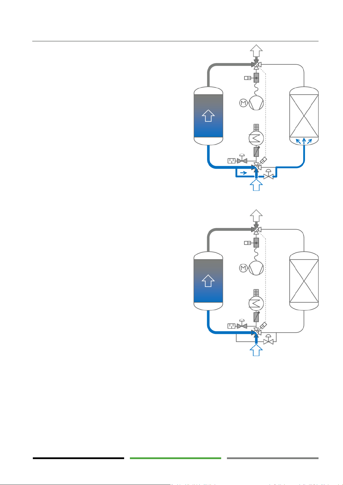
7 a
dsorption
– s
tandby
Pressurisation phase
Duration approx. 3 to 10 min
The pressurisation phase ensures that the two vessels have
the same vessel pressure prior to vessel switch-over.
The regeneration air valve (V3) is closed and the pressurisation valve (V4) is opened. Compressed air flows from one
vessel to the other.
Using the pressure sensor (PT02) the dryer control system
monitors the vessel pressure and compares it to the pressure (PT01) in the other vessel. The next phase begins when
the vessel pressure is almost the same in both vessels.
Technical product description
Standby
Duration approx. 0 hours or longer
Vessel regeneration is now complete and the vessel is immediately ready to operate. During this phase the pressurisation valve (V4) remains open. Vessel pressure in both
vessels is permanently monitored using the pressure sensors (PT01, PT02). Vessel switch-over can only take place if
the vessel pressure is the same.
When the current adsorption phase has been completed,
the vessels are switched over and the process is restarted.
6 adsorption - pressurisation
Monitoring the regeneration phases
The time of all the regeneration phases is monitored. The phases have a minimum and a maximum runtime.
Within this time the progress of the phase is monitored by the relevant sensor and stopped in the event of
reaching the selected limit value.
The above time and temperature values are variables which can be set individually for each dryer. Therefore,
deviations from the above mentioned values are possible.
The minimum and maximum runtime and the limit values are indicated on the control system display.
When reaching the maximum runtime of the phase, a warning or alarm message is displayed accordingly. (→
Page 47)
23
Page 24

Technical
product description
Hot surfaces
4.4 Options
Various options are available for improved operation and special installation site conditions. For detailed information on the options or dryer modification to meet your operating and installation site requirements,
please contact the manufacturer or the responsible sales partner.
Dew point sensor
Control of the adsorption phases changes from purely time-dependent vessel switch-over to load-dependent
operation when using the dew point sensor. The dew point sensor allows for considerable energy savings and
increased dryer performance.
Use of a dew point sensor is highly recommended.
Automatic start-up device (pressure maintaining valve)
The dryer must always be operated with an adequately high pressure in order to avoid excessive flow velocities in the dryer. There is a danger of damage to the dryer. (→ Page 64)
If the dryer is started against a pressureless compressed air network, the compressed air network must be
filled through the dryer. To ensure adequate operating pressure in the dryer the manual valve behind the dryer must be throttled and only be opened very slowly.
In the event the dryer is frequently started against pressureless compressed air networks (e.g. after the weekend) or if there is no personnel available for the start-up procedure, an automatic start-up device is useful. It
ensures that there is an adequately high pressure in the dryer at any time during operation.
Thermal insulation with touch protection
Insulating hot system parts has numerous advantages:
Reducing the heat loss during regeneration and thus considerable energy savings
Reduced heat dissipation into the installation room
Improved and shorter desiccant regeneration process and therefore improved dryer performance
Dryer can be operated in cool and windy environment
Protection of persons against burns on hot dryer surfaces
Frost protection insulation with trace heating
In the event of ambient temperatures below +1°C all the wet-operated components must be protected against
freezing. After evaluating the local conditions a suitable frost protection can be provided.
The "thermal insulation" option meets the requirements of protection against accidental contact
corresponding to most national regulations for accident prevention. Thermal insulation is mandatory in the event the operator does not provide restrictions for accessing the dryer.
24
Page 25

Technical product description
Intake nozzle for regeneration air
Usually, the regeneration air is drawn in from the environment directly on the dryer. If the ambient air at the
place of installation contains dust, moisture or aggressive contamination, the regeneration air must be drawn
in from the outside. For this purpose an intake nozzle can be provided on the dryer.
Intake filter for regeneration air
If the ambient air is heavily contaminated by dust, pollen or insects, the "intake nozzle for regeneration air"
option can be extended by a filter.
Alternative heat sources for regeneration (heating phase)
Using electric power as a heat source is very expensive. Depending on the local availability alternative heat
sources can be used for heating the regeneration air. The following combinations are available:
Steam heat exchanger, for steam pressure of 7 bar and higher (replacing the electric heater)
Combination of steam heat exchanger and electric heater, for steam pressure < 7 bar
Combination of hot water heat exchanger and electric heater
After evaluating the local conditions a suitable solution can be provided.
Loop cooling
Warm and humid ambient conditions have a negative effect on regeneration, especially on the cooling phase.
To avoid negative effects of the environmental conditions on the cooling phase, the regeneration air can be
led in a loop during the cooling phase. The heat dissipates from the loop via a water-air heat exchanger.
This option is recommended for warm and humid environments and is mandatory for tropical ambient conditions.
Paint-compatible version
Compressed air for paint work must be free from silicone and other paint-wetting impairment substances.
For this purpose, the dryer can be manufactured with components and process materials that are free from
these substances or approved for paint work by the automotive industry.
The dryer is manufactured under normal shop-floor environments, however, with a special focus on cleanness.
The product quality can therefore be considered "technically free from paint-wetting impairment substances".
Further options include:
Special voltages: 415 V, 500 V, 690 V, …
Stainless steel versions (completely or partly)
Alternative pressure vessel approvals (PED Module G, ASME U-Stamp, China-Stamp, GOST, …)
Additional pressure vessel documentation (drawing, stress calculation, material certificate 3.1, cer-
tificate of hydrostatic pressure test, welding documentation, …)
Safety valves (valve provided separately)
Weather protection (rain protection, complete insulation, frost protection, increased class of pro-
tection (IP protection class), …)
25
Page 26
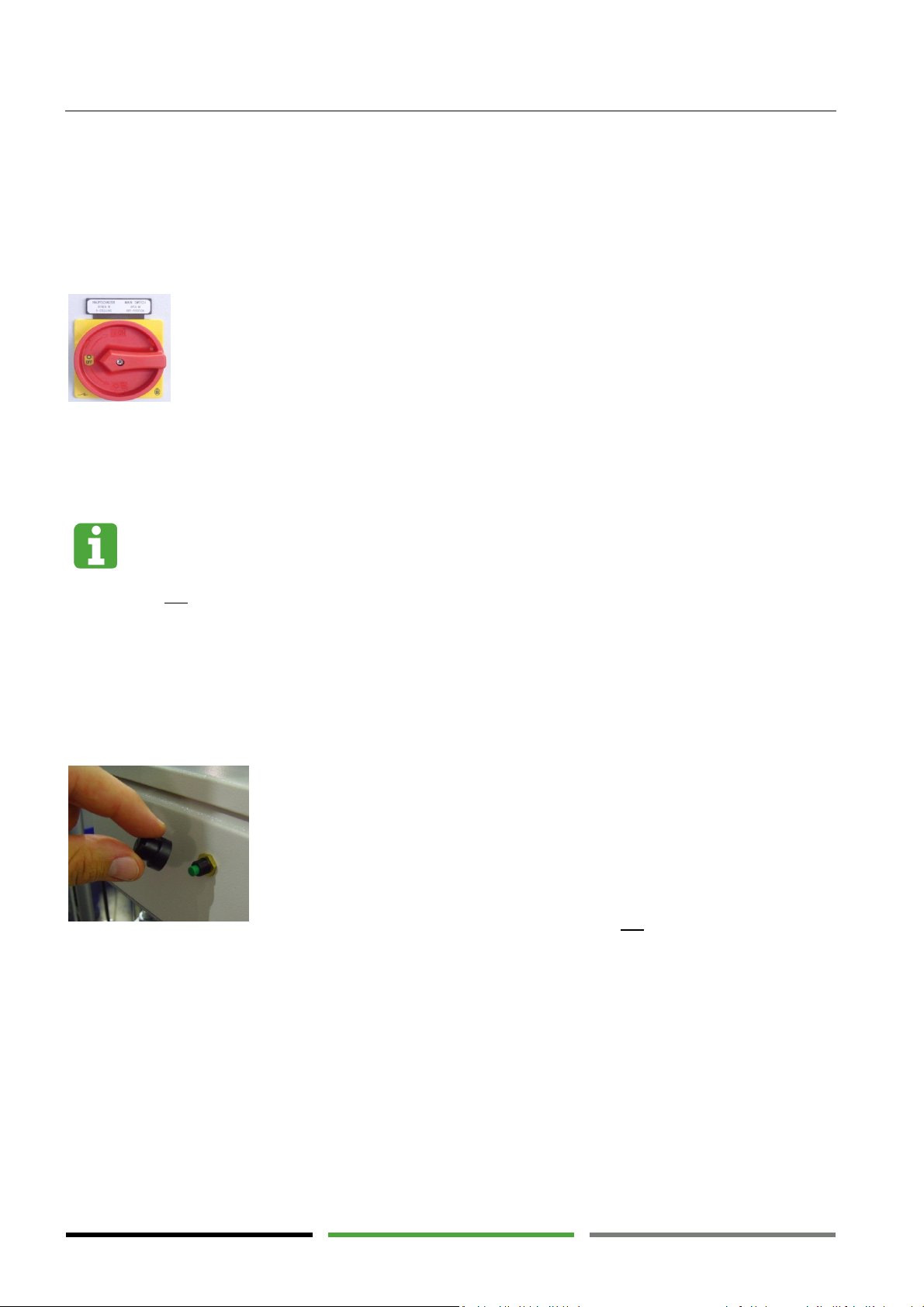
Operating elements
The release button for the temperature limiter can be found on the junction box
The main circuit breaker disconnects the control box and the connected dryer
Switching off the dryer
properly
5. Operating elements
The following sections describe the dryer components used for dryer monitoring and dryer operation.
5.1 Main circuit breaker
components from the power supply.
0-OFF = power supply disconnected
I -ON = power supply switched on
The main circuit breaker can be protected against unintentional reclosing. Latch the main circuit breaker in the
"I-OFF" position by inserting and locking a lock or a cable tie in the eyelet of the red rotary switch.
Switching off the dryer during the heating phase directly via the main circuit breaker may damage
the electric heater.
Do not use the main circuit breaker for directly switching off the dryer.
The dryer is switched ON and OFF using the touch panel. (→ Page 31)
Only use the main circuit breaker for direct dryer switch-off if the dryer must be immediately disconnected from the power supply for safety reasons.
5.2 Release button for temperature limiter
of the heater.
If the control system displays the "alarm heater limiter switch" error message
on the touch panel, the corresponding error can be removed here. (→ Page 47)
1) Wait until the heater has cooled down. The limiter can only be reset if the
electric heater is in a cold state.
2) Remove the black protective cap from the release button.
3) Press the coloured release button. (You may not feel a click. Nevertheless,
the limiter has been reset.)
4) Make sure that the error message is no longer relevant.
5) Screw the black protective cap on the release button again.
26
Page 27
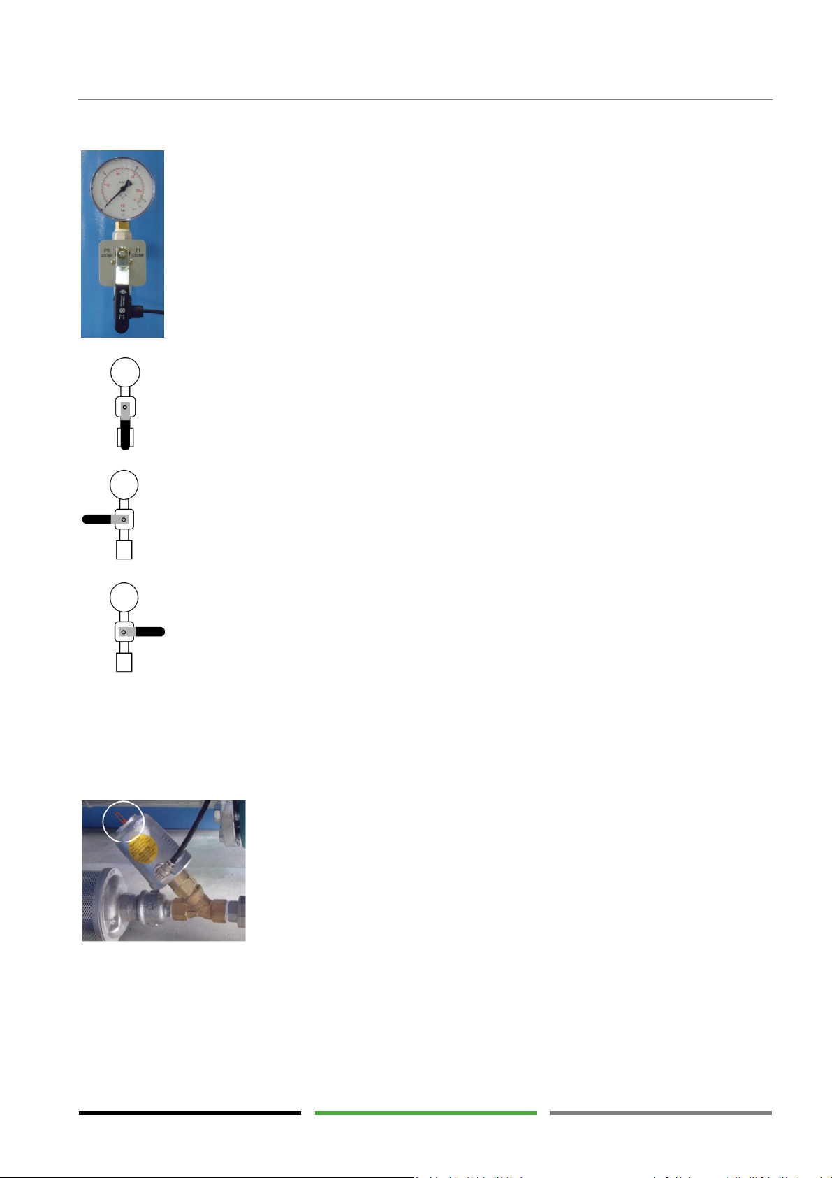
The PI01/PI02 pressure gauges indicate the relevant vessel pressure.
The position of valves V4 and V5 is indicated by means of a small, coloured pin
5.3 Pressure gauge
Operating elements
In the event of a power failure the pressure gauges also indicate whether the
vessel is under pressure.
Compare the indicated value to the value on the touch panel in order to check
the function of the PT01/PT02 pressure sensors. (→ Page 35)
For maintenance reasons the HV1/HV2 manual valve can be closed.
Remove the screws to the left and to the right of the hand lever.
Turn the hand lever in the position shown below.
After maintenance, turn the hand lever back to normal position and insert the
screws again.
HV1/HV2 valve positions:
Normal position:
Vessel is connected to pressure gauge and pressure sensor
PT pressure sensor maintenance:
Vessel is only connected to pressure gauge
PI pressure gauge maintenance:
Vessel is only connected to pressure sensor
5.4 Valve position indications
All the automatically operated valves are provided with a position indication. For analysing an error the actual
state of the valve can be compared to the state set in the control system. (→ Page 35)
on the actuator.
Pin protrudes approx. 2 cm from the actuator = OPEN
Pin is almost completely inserted in the actuator = CLOSE
27
Page 28
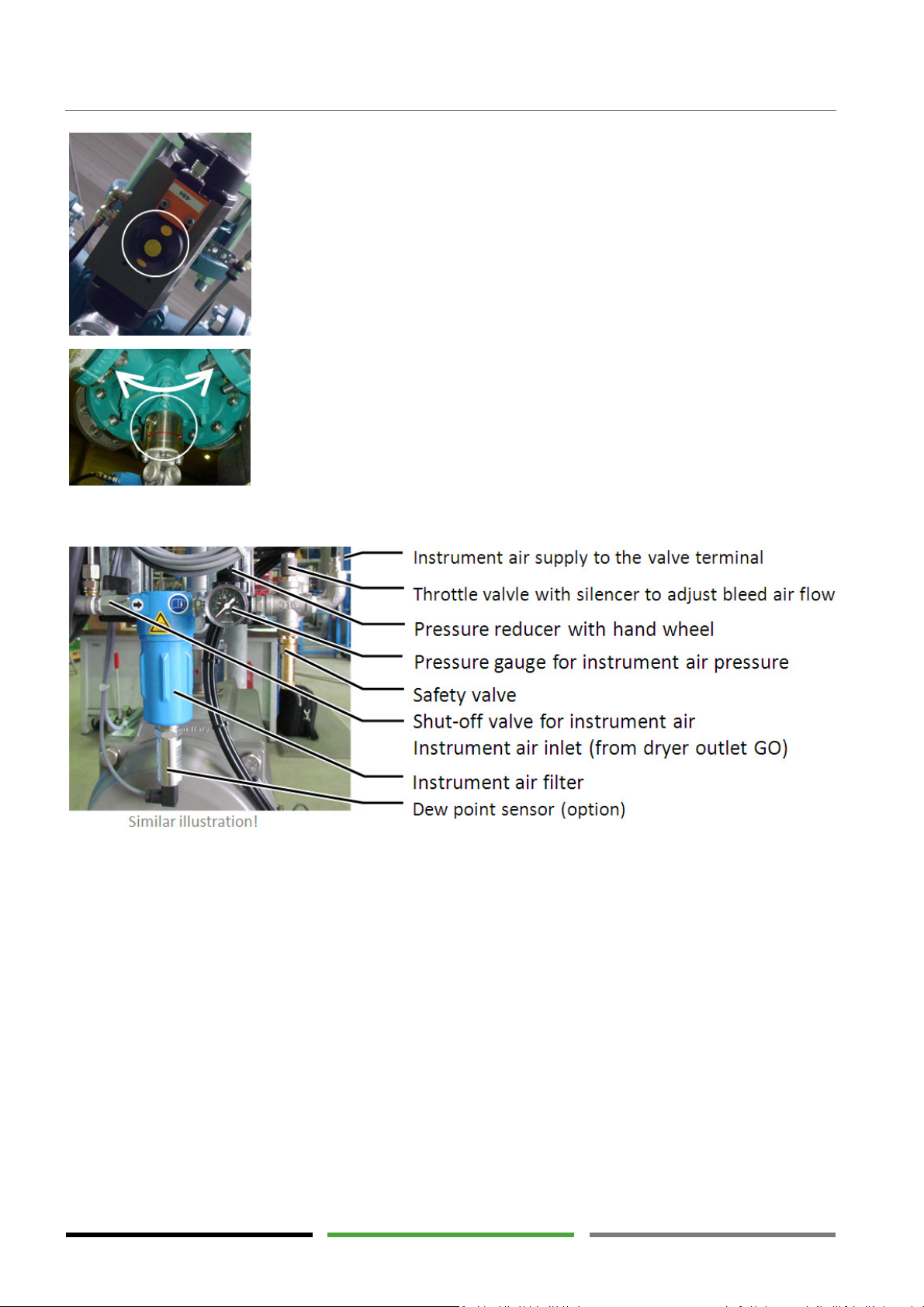
Operating elements
The position of the V3 regeneration valve is indicated by means of a black
-
The position of the main valves V1 and V2 is indicated by markings on a small
yellow cylinder on the actuator. A row of points or a line indicates the position
of the valve disc.
Marking horizontally to piping installation direction = OPEN
Marking vertically to piping installation direction = CLOSE
metal cylinder on both ends of the cardan shaft.
Grooves indicate the openings of the valve channels and a red line indicates
which of the two flanges are connected to one another.
5.5 Instrument air supply and pilot valve terminal
The instrument air is supplied internally, i.e. from the dryer outlet, and forwarded to the pilot valve terminal
via an instrument air filter and a pressure reducer. The electrical control signals from the dryer control system
are pneumatically amplified using the pilot valve terminal and transferred to the valve actuators. LEDs indicate
which pilot valve is actuated. The pneumatic diagram shows the connection between pilot valve and the corresponding process valve.
1) For maintenance of the instrument air supply cut off the instrument air at the small shut-off valve.
The pressure in the filter, valve terminal and valve actuators is released through a little hole in the
shut-off-valve.
2) Monitor the pressure gauge on the pressure reducer. Don’t proceed with the work before the
pneumatic system is depressurised.
3) After maintenance work the shut-off valve reopened.
28
Page 29
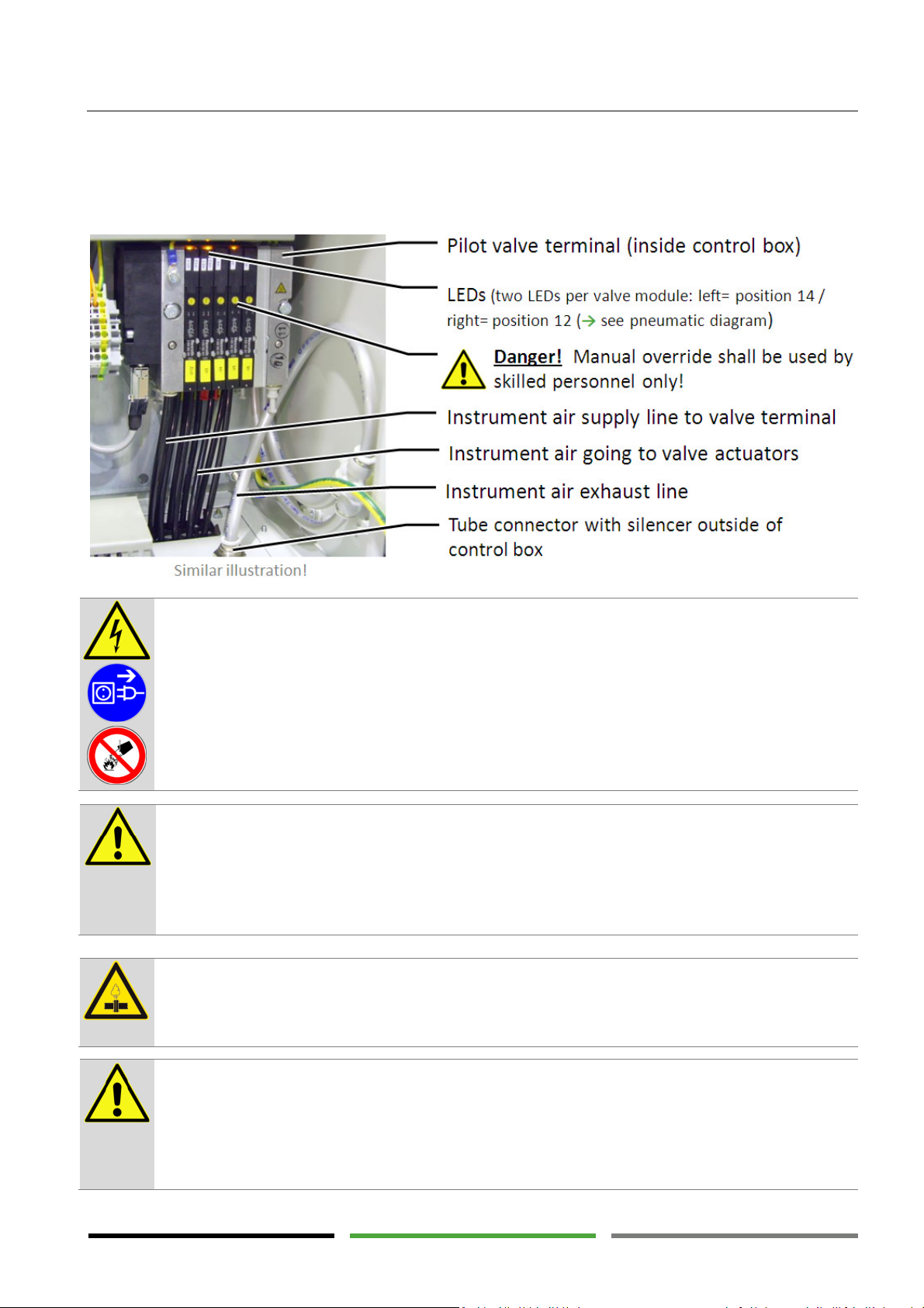
Operating elements
DANGER !
– Electric voltage
CAUTION !
– Qualification and experience required
DANGER !
– Dangerous valve position
DANGER !
– Overpressure
Make sure that the pressure reducer is set to a value of 6 bar to 7 bar. The instrument air pressure must not
exceed 8 bar!
In the event of incorrect valve positions always check the instrument air pressure on the pressure reducer.
For a schematic diagram of the instrument air supply, please refer to the pneumatic diagram in the appendix.
The dryer is operated at electric voltages up to 690 V.
Touching live parts may result in serious injury or death.
Work on electrical components must only be carried out by qualified and authorised personnel.
Use a voltage detector to make sure the dryer has been disconnected from the power supply and
that there are no live parts before starting maintenance work.
In the event of fire, do not extinguish the fire using water.
Persons working on and with the dryer have to be qualified personnel who, because of their qualification and experience, are familiar with handling compressed air systems and electrical systems.
If you are not experienced in using these systems, please ask the relevant experts for help. We
highly recommend that commissioning and maintenance be carried out by the manufacturer or
one of the authorised service partners.
The dryer is under pressure.
Suddenly escaping compressed air may result in serious injury.
Do not carry out mechanical or electrical work on the dryer as long as the dryer is under pressure.
Manipulation of the pneumatic system can cause dangerous valve malpositioning.
False valve position can cause high quantities of suddenly escaping compressed air. Suddenly escaping compressed air may result in severe damage, serious injury or death.
Never actuated the manual override of the pilot valve terminal! Never change the instrument air
tubing.
29
Page 30
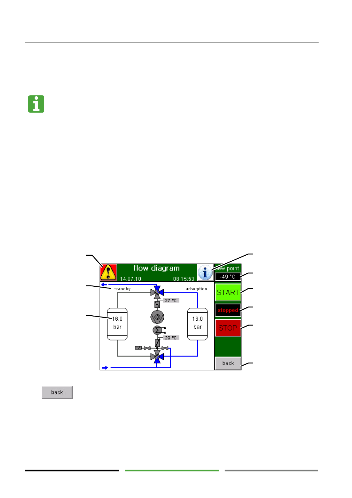
Operating elements
Delicate touch panel
sages" window
5.6 Touch panel
The dryer is operated using a touch panel on the control box. Touching the screen allows for executing functions and requesting different information.
Hard or sharp-edged objects may damage the touch panel or render it unusable. Only operate the
touch panel using the fingers or a soft object. The touch panel reacts to light pressure. Never attempt to activate a function field by means of intense pressing or tapping.
5.6.1 Overview of the operating elements
The user interface of the touch panel contains embossed functions fields. Touching these function fields using
a finger or a soft object enables calling of the relevant functions.
Fields that are not embossed are used for indication only. These fields can only be activated when changing to
a higher password level.
Menu window: "main menu"
Change to "alarm mes-
Function field:
Indication:
Operating phase
Indication
Vessel pressure
Function field:
Change to "info" window
Indication:
Dew point
Function field:
Start dryer
Indication:
Operating status
Function field:
Change to "dryer OFF"
window
Press to return to the previous menu window.
30
Function field:
Previous window
Page 31
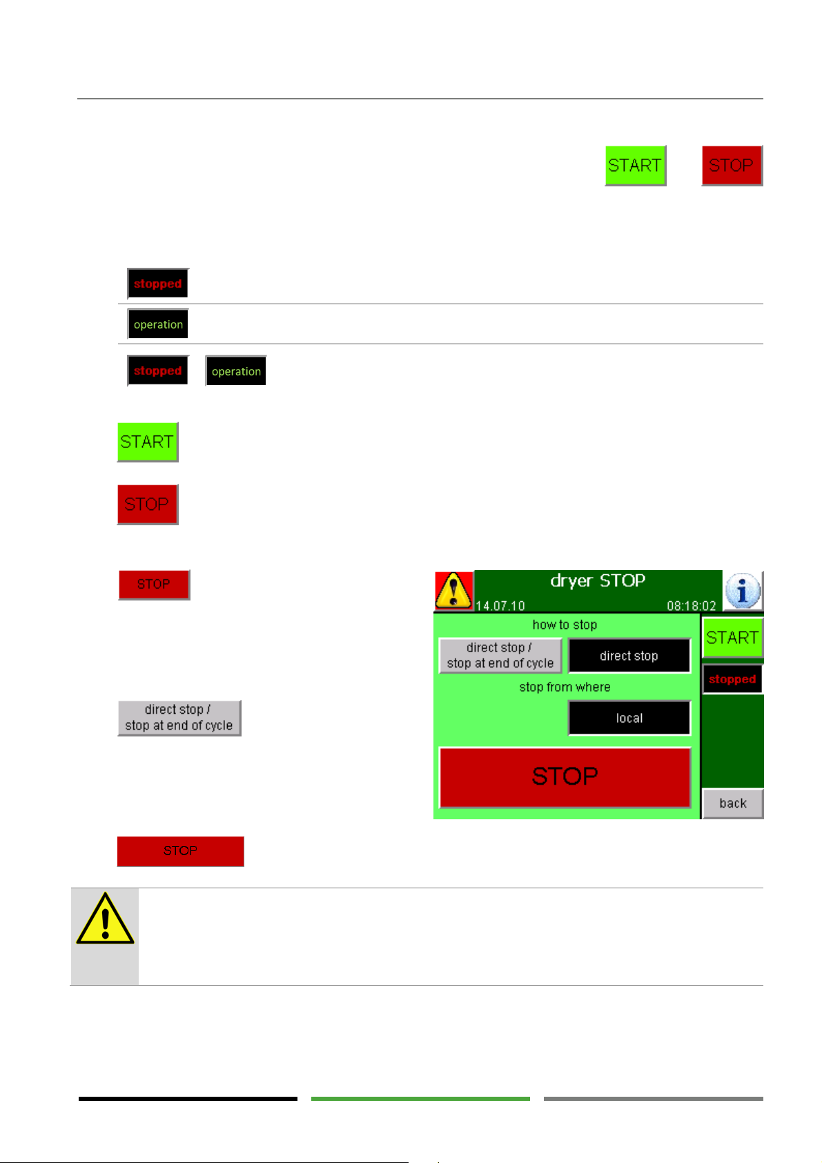
Operating elements
=
=
=
Stop has been pressed and the dryer still is in the stopping sequence
CAUTION
! Risk of overheating the blower mo
tor
5.6.2 Starting and stopping the dryer control system
The "main menu", "status" and "process parameters" menu windows contain the. and.
function fields.
The indicator between these two function fields shows the current state of the control system:
The control system has been stopped. The dryer stops in the current
state until the control system is restarted.
The control system is running. The dryer performs the operating phases.
+
Press to directly start the control system.
(see below). The indicator alternates between "stopped" and "operation".
Press to access the "dryer OFF" menu window (see below).
5.6.2.1 Menu window: "dryer OFF"
Press in any window to access the "dryer
OFF" menu window.
The dryer can be stopped by means of different stopping sequences.
Press to change between the two
different stopping sequences.
The black field to the right of the function field indicates the stopping sequence currently selected.
Press to activate the selected stopping sequence.
The motor of the blower consumes particularly high power during the start-up of the blower. This
causes the motor to heat up.
Avoid overheating of the motor due to frequent start-us.
The maximum number of motor start-ups shall be limited to 3 per hour.
31
Page 32
Operating elements
"
direct stop
"
The stopping process is started immediately.
"
stop at end of cycle
"
The operating indicator alternates between "
stopped
" and "
operation
".
Direct stop ... during the heating phase
Stop at end of cycle
Valves V4 and V5 are closed.
The electric heater is switched off.
The blower is also switched off with a delay of a few seconds.
After the blower has been switched off the dryer program is stopped.
The currently running regeneration phase continues running until reach-
After reaching the "pressurisation" phase the dryer program is stopped.
Depending on the cycle phase the above mentioned events may have
been fulfilled already. In this case the dryer program stops immediately.
This stopping mode should only be used if immediate stopping of the
dryer is absolutely necessary.
ing the pressurisation phase.
The operating indicator shows "stopped".
This stopping sequence is recommended. It ensures that the dew point
quality can definitively be achieved when restarting the dryer.
Press to restart the dryer program. The currently running stopping sequence is interrupted and the dryer operates in normal mode.
The "Starting and stopping the dryer locally or remotely" section describes how to select the "local / remote"
stopping sequence. (→ Page 47)
A "direct stop" during the heating phase will not always ensure adequate regeneration.
After switching of the blower the temperatures at the heater may be very high. This may lead to
malfunctions, and affects the heater service life.
We therefore recommend always stopping the dryer using the "stop at end of cycle" function. This
function ensures that regeneration is performed properly and the heater is operated in a gentle
mode.
"Stop at end of cycle" can also be performed when there is no more operating pressure. This mode
is particularly suitable for weekend shutdown with the compressor switched off.
Stopping the dryer via the "stop at end of cycle" function ensures that all the dryer components
have cooled down. In this way, maintenance work can be performed more easily.
The alternating operating indicator – "stopped" and "operation" – shows that the stopping sequence has been activated correctly.
32
Page 33
Operating elements
5.6.3 Menu window: "alarm message"
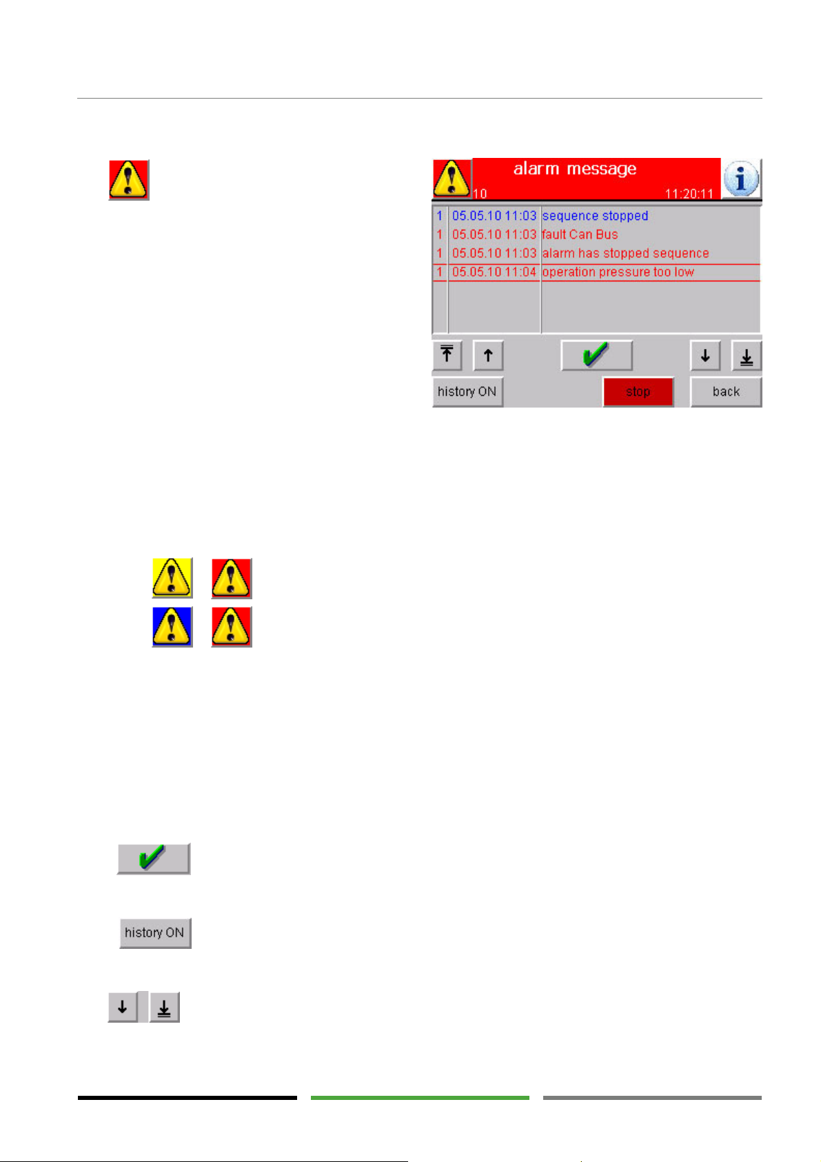
The function field is shown in each menu window and directly leads to the "alarm message" menu
window.
There are two types of alarm messages:
1. Alarms (red) indicate errors that directly affect the
program sequence. Alarms require immediate attention. It may be necessary for the operating personnel to take relevant measures.
2. Warnings (blue) indicate operating errors that do
not directly affect the program sequence. However, warnings refer to a malfunction. Occasionally appearing warnings are not unusual. However, if similar warnings are repeated, it may be necessary for the operating personnel to take relevant measures.
A list of all the error messages, their meaning and measures to be taken can be found on → page 47.
In the event of new error messages the function field flashes in different colours.
+
+
If all the error messages have been acknowledged and if no new error message is present the function field is
not flashing.
The number in the first column of the "alarm message" menu window indicates the message status:
1 = the message has appeared
0 = the message is no longer relevant (i.e. the reason of the message does no longer exist)
X = the message has been acknowledged
Press to acknowledge and mark the message. The message is removed as soon as the message is
no longer relevant.
One alarm message or several alarm messages are indicated.
One warning or several warnings are indicated.
Press to access all the messages from the past which are no longer relevant and have been
acknowledged.
Use to scroll through the list or to be directed to the beginning or to the end of the list.
33
Page 34
Operating elements
5.6.4 Menu window: "info"
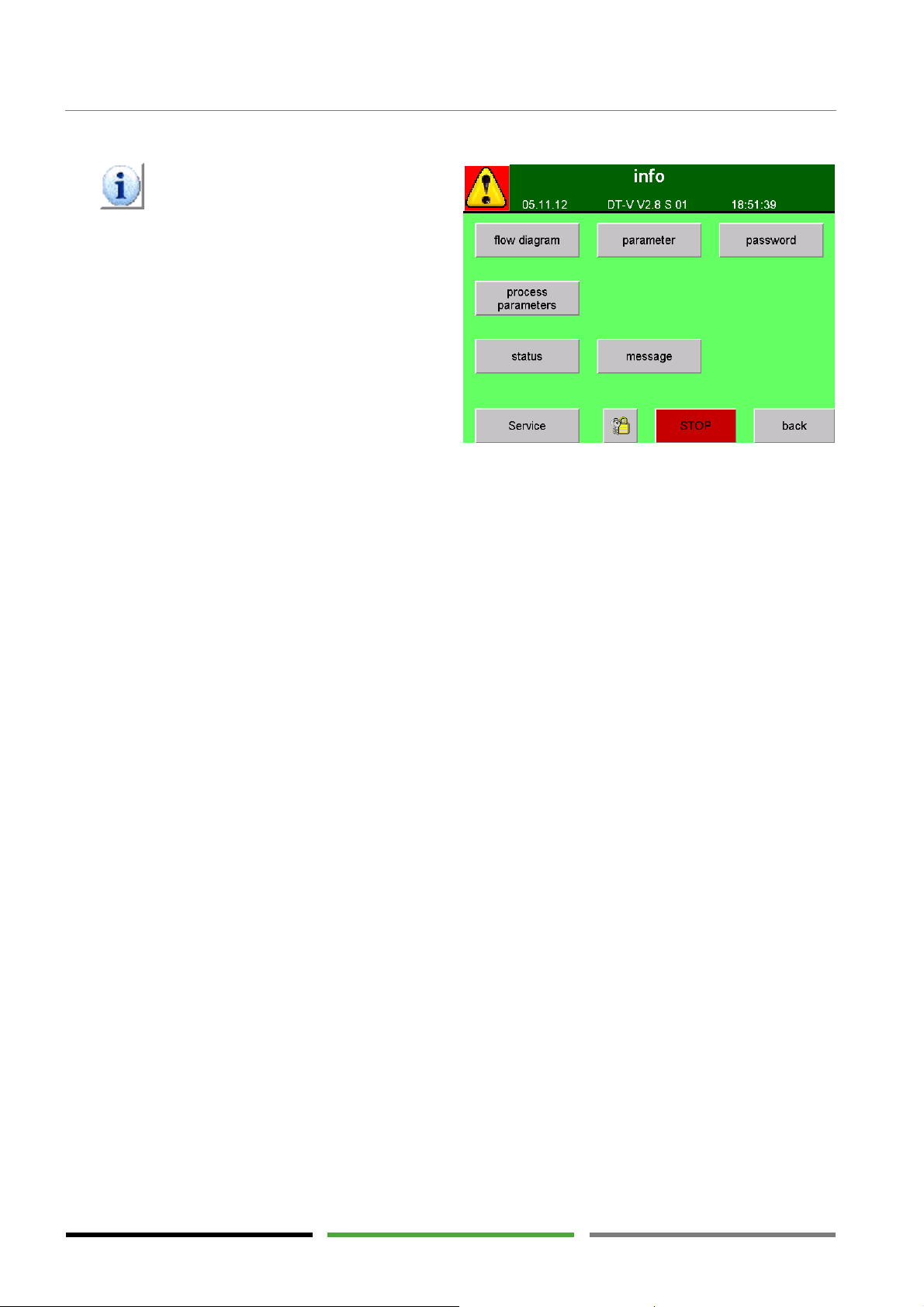
The function field is shown in each menu window and directly leads to the "info" menu window.
All the important menu windows can directly be selected from the "info" menu window. Pressing a function field calls the according menu window.
34
Page 35
5.6.5 Menu window: "process parameters"
Press to access the "process
parameters" menu window.
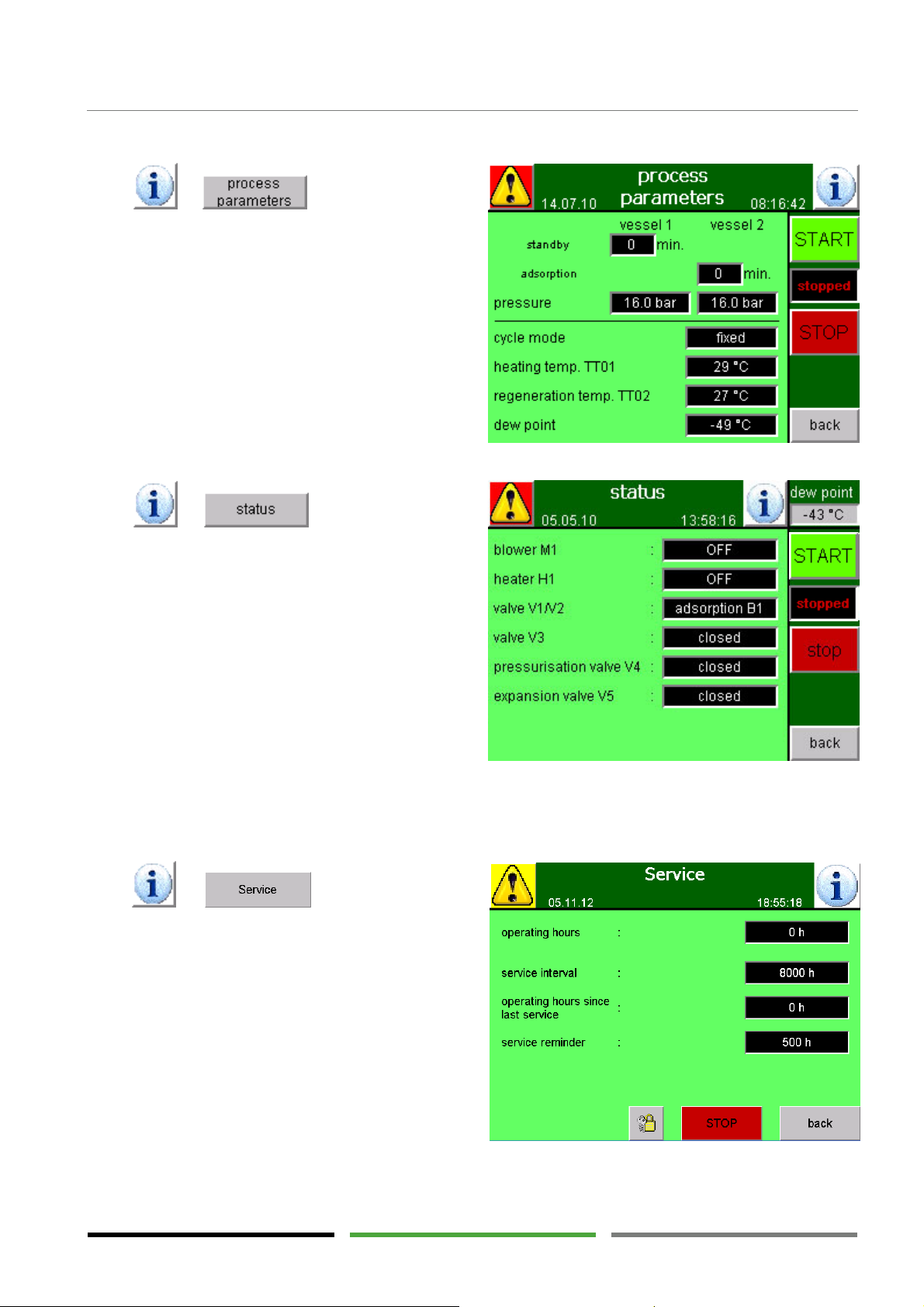
This window shows the current status using measured
values, the time elapsed, the selected operating mode
and the current operating phase.
This window shows the dryer cycle progress at a
glance.
5.6.6 Menu window: "status"
Press to access the "status"
menu window.
Operating elements
This window shows the operating states of the valves,
the heater and the blower.
The states indicated correspond to the states of the
outputs on the control system. Use this window to
define the desired state of the components (compare
→ page 27).
This menu window can be useful for troubleshooting
because the desired state and the actual state of the
components can be compared.
5.6.7 Menu window: "service"
Press . to access the "service"
menu window.
Operating hours indicates for how long the dryer
has been in operation since the first commissioning.
Service interval indicates in which intervals
maintenance is recommended.
Operating hours since last service indicates how
much time has passed since the last maintenance.
A warning is displayed when the Operating hours
since last service have reached the Service interval.
Service reminder indicates in which intervals a reminder for maintenance is displayed.
35
Page 36
Operating elements
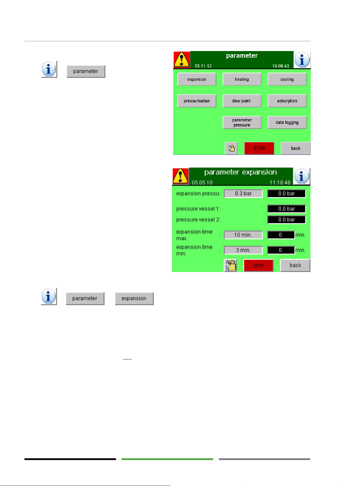
5.6.8 Menu window: "parameter"
Press to access the "parameter" menu window.
A group of additional menu windows can be opened
from this window. The additional menu windows can
be used to read all the settings and limit values used
for controlling the dryer.
5.6.8.1 Menu window: "parameter expansion"
This menu window is part of the "parameter" group
and compares the preset limit values to the current
measured values or time values.
The grey fields indicate the preset limit values.
The black fields indicate the current measured values
or the time elapsed.
As soon as the measured value/time value reaches the
limit value, the next program step will be executed.
Press to access the "parameter expansion" menu window.
The expansion phase runs at least until the expansion time min. time limit is reached.
As soon as the vessel pressure reaches the expansion pressure limit value, the next program step will be executed.
In the event the vessel pressure does not reach the expansion pressure limit value within the expansion time
max. time limit, an alarm message is displayed and the program is stopped until the limit value is reached.
36
Page 37
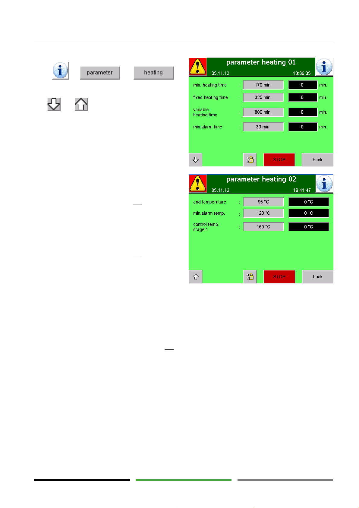
5.6.8.2 Menu window: "parameter heating"
Press to
access the "parameter heating" menu window. This
window comprises two screens.
Use and to change between the screens.
The heating phase runs at least until the min. heating
time limit is reached.
As soon as the temperature of the regeneration air
exhausting from the vessel reaches the end tempera-
ture limit value, the next program step will be executed.
In "fixed" cycle mode:
In the event the temperature does not reach the end
temperature limit value within the fixed heating time
limit, a warning is displayed and the next program step
will be executed.
Operating elements
In "variable" cycle mode:
In the event the temperature does not reach the end
temperature limit value within the variable heating
time limit, a warning is displayed and the next pro-
gram step will be executed.
The control temp. stage 1 is the setpoint for the temperature of the hot regeneration air flowing into the vessel. The control temperature is used for switching the heater on and off.
Additional control temperatures will be displayed in case there are more heater stages than one.
The temperature of the regeneration air flowing in must have reached the control temp. limit value within the
control time limit. In the event the limit value is not reached, an alarm message is displayed.
37
Page 38
Operating elements
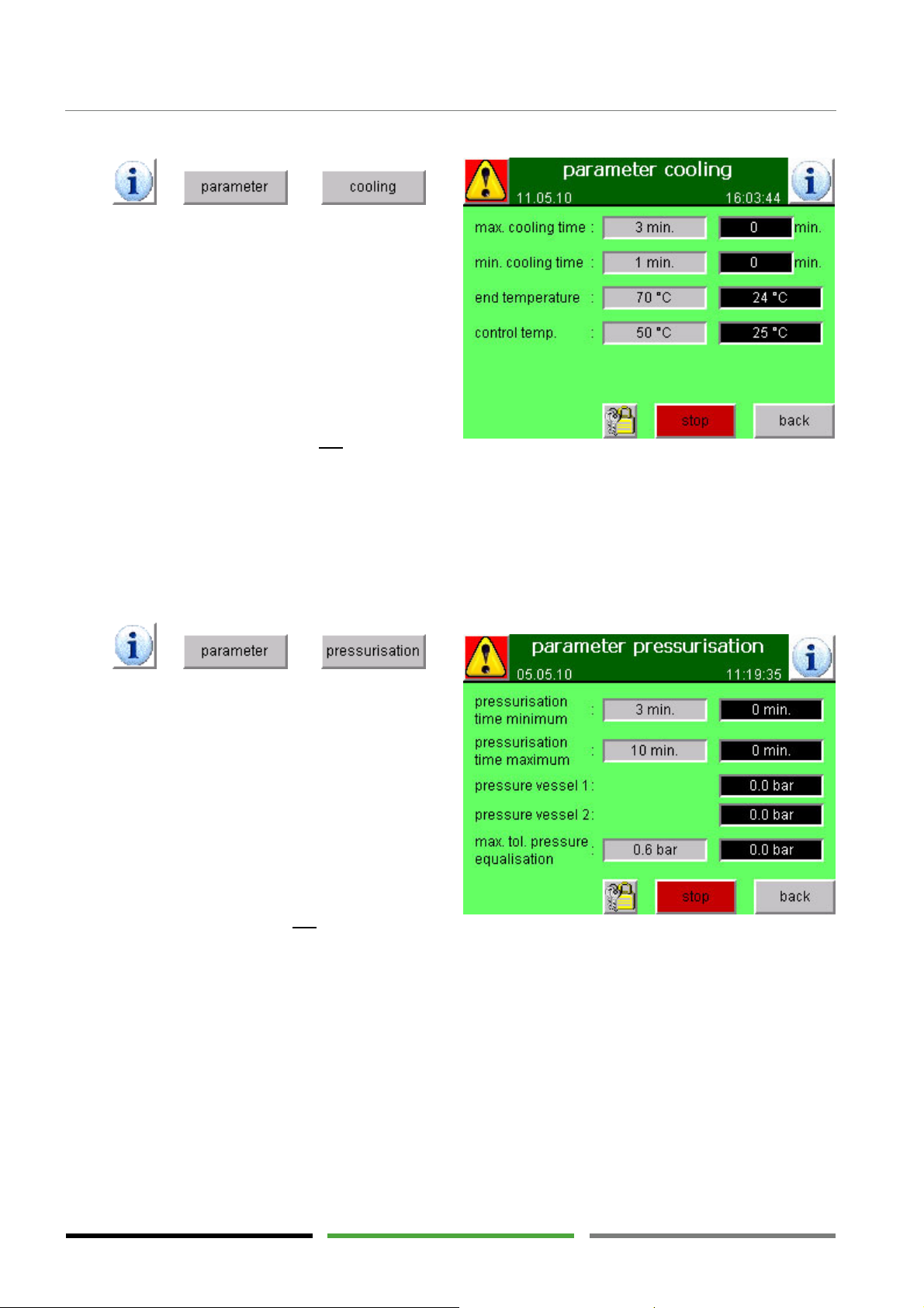
5.6.8.3 Menu window: "parameter cooling"
Press to
access the "parameter cooling" menu window.
The cooling phase runs at least until the min. cooling
time limit is reached.
As soon as the temperature of the regeneration air
exhausting from the vessel reaches the end tempera-
ture limit value, the next program step will be executed.
In the event the temperature does not reach the end
temperature limit value within the max. cooling time limit, a warning is displayed and the next program step
will be executed.
If, during the cooling phase, the temperature of the cold regeneration air flowing into the vessel exceeds the
control temp. limit value, a warning is displayed.
5.6.8.4 Menu window: "parameter pressurisation"
Press to
access the "parameter pressurisation" menu window.
The pressurisation phase runs at least until the pres-
surisation time minimum time limit is reached.
In the event the pressures in both vessels is equalised
before reaching the max. tol. pressure equalisation
limit value, the next program step will be executed.
In the event the pressures do not adjust within the
pressurisation time maximum time limit, an alarm
message is displayed and the program is stopped until
the limit value is reached.
38
Page 39
Operating elements
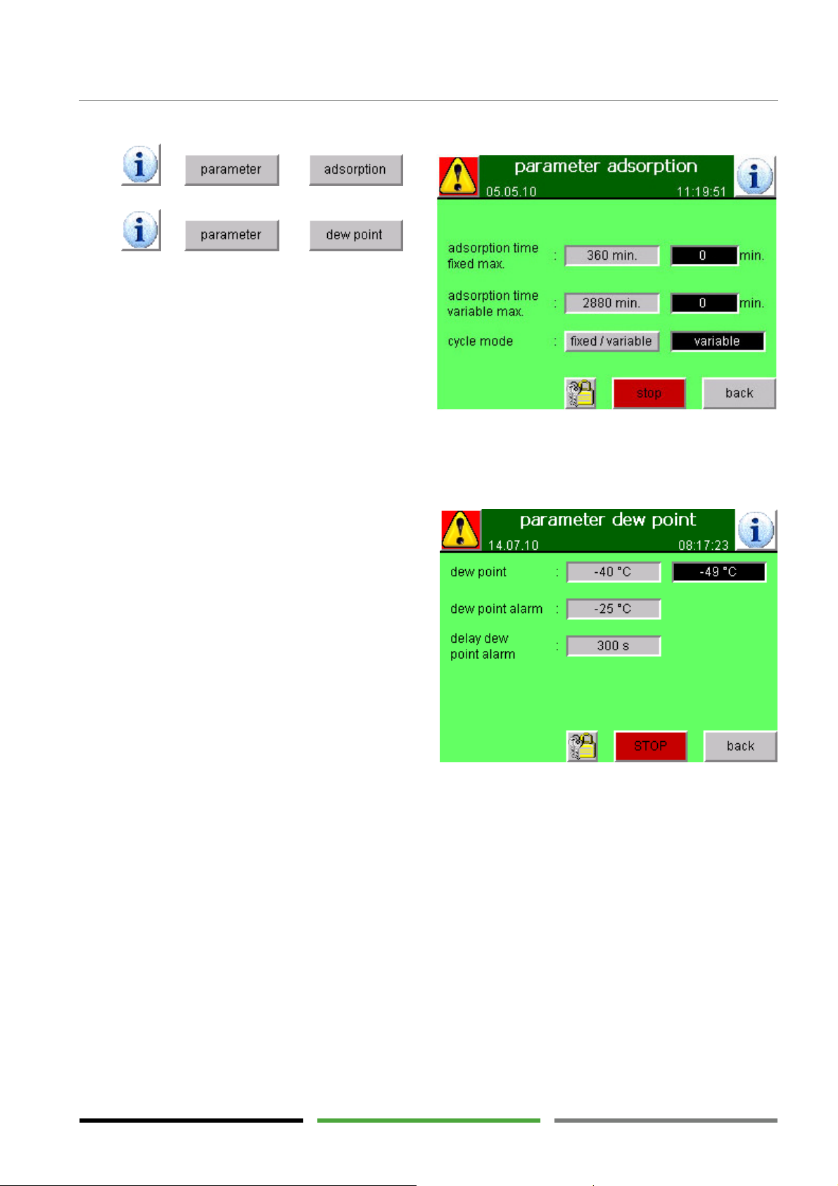
5.6.8.5 Menu windows "parameter adsorption" and "parameter dew point"
Press to
access the "parameter adsorption" menu window.
Press to
access the "parameter dew point" menu window.
These windows are used to define the limit values for
controlling the adsorption phase.
Cycle mode
"fixed" = time-controlled adsorption phase
"variable" = dew point-controlled adsorption
phase
Section "Time control and dew point control" describes how to change between the two cycle modes. (→
Page 44)
In the "fixed" cycle mode the adsorption phase runs
exactly until reaching the adsorption time fixed max.
time limit.
In the "variable" cycle mode the adsorption phase
runs until reaching the dew point limit value.
However, the adsorption phase is stopped in any case
when reaching the adsorption time variable max.
time limit.
The minimum possible adsorption time is defined by
the duration of the regeneration phase.
In both cycle modes regeneration always has priority
over adsorption. Vessel switch-over can only take
place when the regeneration phase has been completed.
In the event the dew point measured value exceeds the dew point alarm limit value, an alarm message is displayed after the delay dew point alarm delay time has elapsed.
The "Setting the dew point limit value" section describes how to change the dew point limit value and the dew
point alarm limit value. (→ Page 45)
39
Page 40
Operating elements
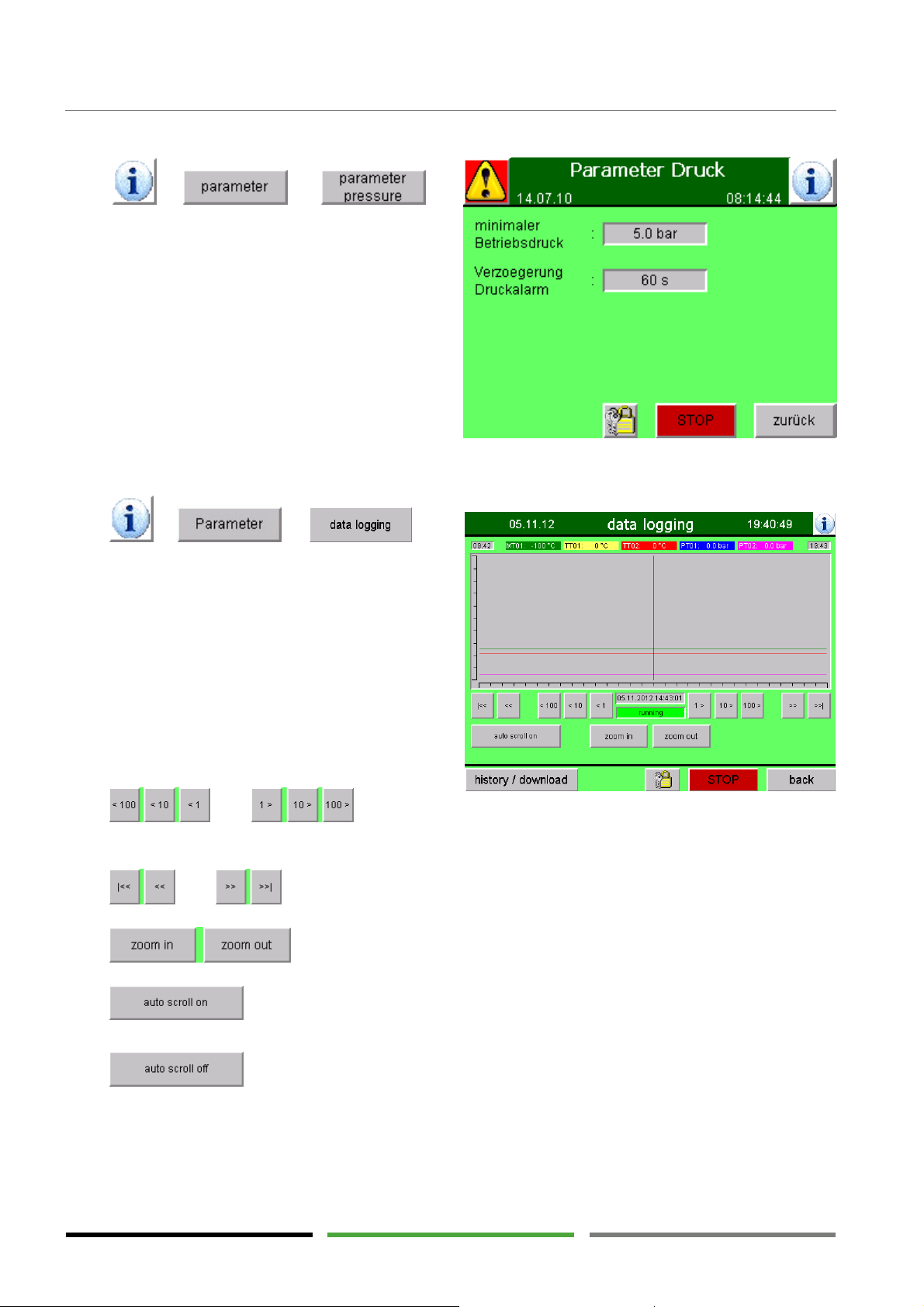
5.6.8.6 Menu window "parameter pressure"
Press to
access the "system parameter" menu window.
This window is used to define the parameters for operating pressure.
In the event the operating pressure falls below the
min. operation pressure limit value, an alarm message
is displayed after the delay pressure alarm delay time
has elapsed.
5.6.8.7 Menu window „data logging“
Press to
access the "data logging" menu window.
Here the graphs of the analogue sensors are displayed
versus time. The readings serve the service technician
for the optimisation of the process parameter and the
analysis of malfunctions.
The vertical black line is a time indicator. The relevant
reading for this time indication are shown in the headline of this window.
Press and to move the
time indicator along the time axis to display the readings for different times.
Press. and to move the time frame for and backward.
Press to widen or narrow the visible time interval.
Press to continuously update the diagram to the current time. The visible time frame
moves automatically to the current time and thus always shows the current measurements.
Press to lock into position the selected time frame.
Note: The function ‘auto scroll off’ is active when “auto scroll on” is displayed. Press “auto scroll on” to activate the function ‘auto scroll on’. The function field will now offer the change back to ‘auto scroll off’
40
Page 41
Operating elements
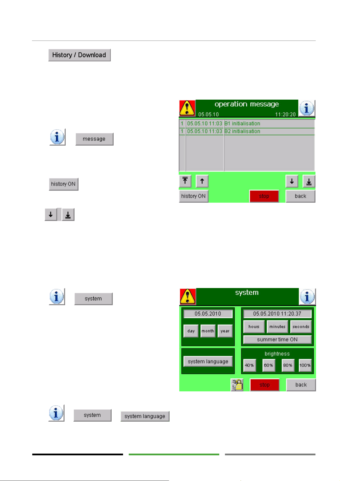
Press to get to the menu window „history“. Information about this window can be
found on
5.6.9 Menu window: "operation mes-
Press to access the "operation message" menu window.
This window shows the current operating phase.
Press to access all the messages from the
past which are no longer relevant.
→ page 46.
sage"
Use to scroll through the list or to be directed to the beginning or to the end of the list.
The number in the first column of the "operation message" menu window indicates the message status:
1 = the message has appeared
0 = the message is no longer relevant (i.e. this operating phase has been completed)
5.6.10 Menu window: "system"
Press to access the "system"
menu window.
This window can be used for the basic settings of the
display.
Press to change the display language.
41
Page 42
Operating elements
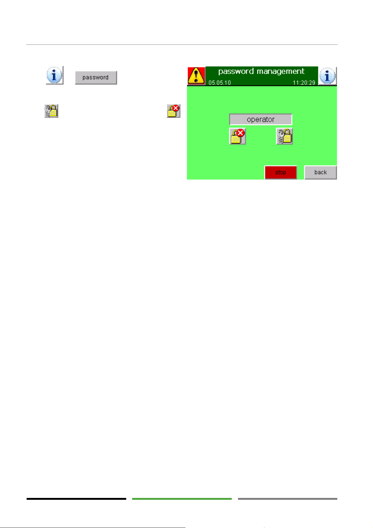
5.6.11 Menu window: "password management"
Press to access the "password management" menu window.
Press to log in on a password level or press
to log off from the password level.
For further information, please refer to the following
pages.
42
Page 43
Operating elements
5.7 Operation in the "operator" password level
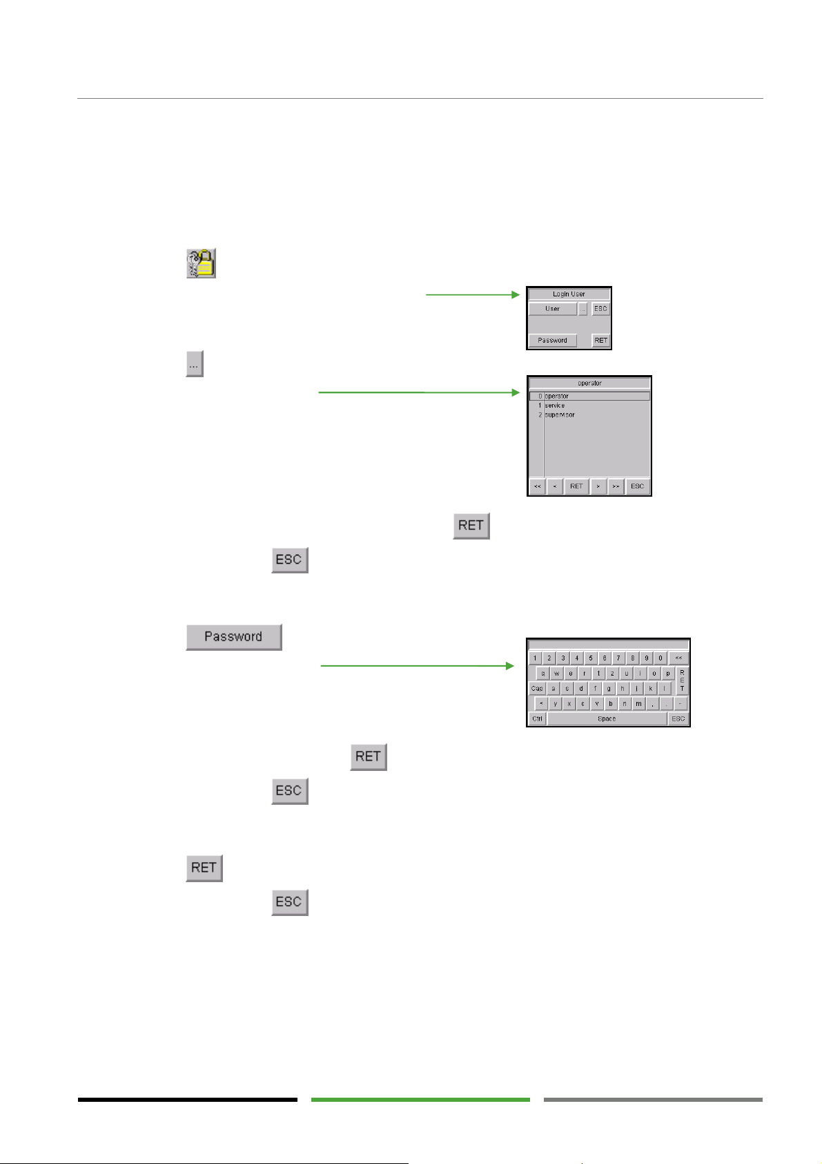
When logging in on the "operator" password level additional functions can be accessed.
5.7.1 Login
Most of the menu windows provide the login option.
1) Press .
The "Login User" password menu appears.
2) Press .
The user menu appears.
3) Select "operator" using the arrow keys and press to select the highlighted user.
Alternatively, press to quit the menu again.
The screen returns to the "Login User" password menu.
4) Press in the "Login User" password menu.
A keypad appears.
5) Enter password "333" and press .
Alternatively, press to quit the keypad again.
The screen returns to the "Login User" password menu.
6) Press to log in.
Alternatively, press to quit the password menu again.
The screen returns to the previously displayed menu window.
On the "operator" password level additional functions can be executed. These functions are described in the
following.
43
Page 44
Operating elements
Dew point control: "variable" cycle mode
5.7.2 Time control and dew point control
For a description of time control and dew point control, please refer to → page 20.
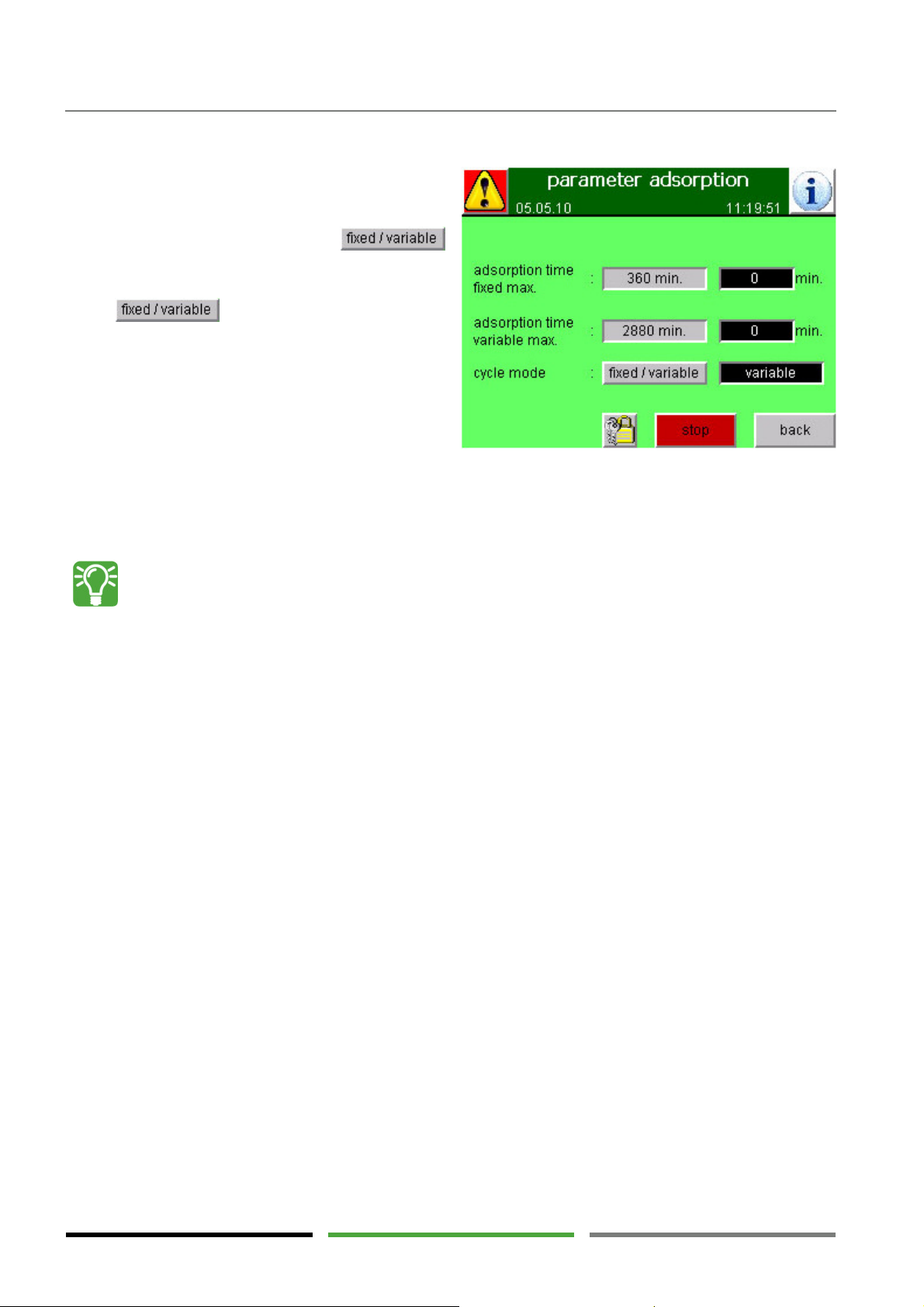
On the "operator" password level the
function field is activated.
Press to change between the two
cycle modes. The adjacent black field indicates the
currently selected cycle mode.
Cycle mode
"fixed" = time-controlled adsorption phase
"variable" = dew point-controlled adsorption
phase
The "variable" cycle mode can only be selected if the optional dew point sensor is connected.
When the dryer is optimally operated the desiccant is laden with water until the maximum drying
capacity is reached. Dew point control enables the desiccant to be optimally laden even with load
variations.
This has numerous advantages:
A) The entire desiccant is used for the "drying work". This drying work activates the desiccant.
The dew point quality is improved and the dryer spare capacity is increased.
B) Less energy-intensive regeneration cycles have to be performed. The operating costs are re-
duced considerably.
C) Effects on the desiccant due to temperature changes are reduced. Service life of the desiccant
is increased.
"Fixed" cycle mode is useful in the event of a defective dew point sensor or if vessel switch-over is
to be carried out for testing purposes.
44
Page 45
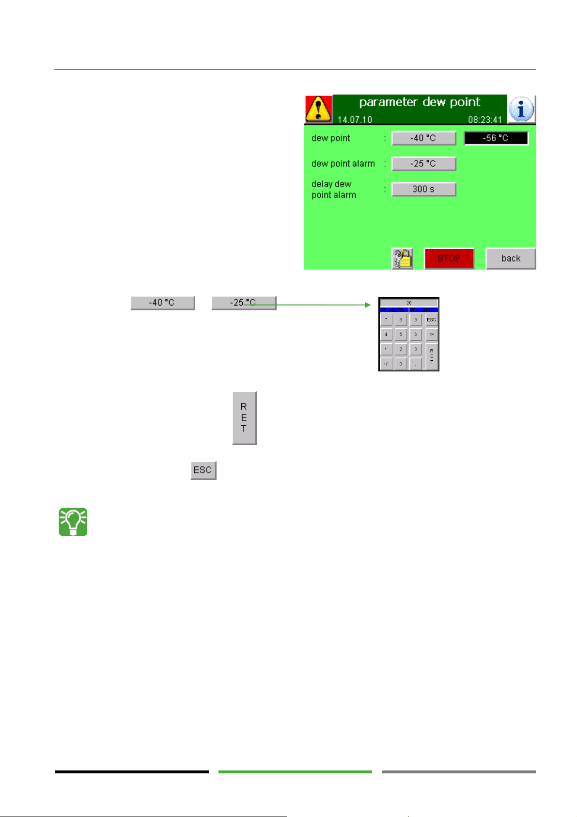
Properly selecting the dew point l
imit value
5.7.3 Setting the dew point limit value
On the "operator" password level the function fields
for entering the dew point limit value, the dew point
alarm limit value and the time delay dew point alarm
are activated.
1) Press or .
A numeric keypad appears.
Operating elements
2) Enter a new value and press to apply the new value. When entering the value make sure to
enter the negative sign "-" in front of the number.
Alternatively, press to quit the numeric keypad again without changes.
The dew point limit value is a fixed control parameter which leads to vessel switch-over when exceeding the limit value. This means that it is not a "control button for setting the desired dew
point". Setting a better dew point value does not improve drying performance but leads to an earlier vessel switch-over.
If the dew point limit value is set "too good" (i.e. better than the dryer performance under the
given conditions), vessel switch-over and a new regeneration procedure is directly started upon
completion of a regeneration phase. This rapid succession of regeneration cycles consumes unnecessary energy and reduces dryer performance.
How to select the dew point limit value properly:
1) Select a dew point limit value that can still be tolerated, however, it must not be worse than
-10°C.
2) Monitor the development of the dew point measured value for some days of operation.
3) Select a dew point limit value that is approximately 10°C worse than the dew point that is usu-
ally reached, however, it must not be worse than -10°C.
4) Select a dew point alarm limit value that is at least 10°C worse than the dew point limit value.
45
Page 46
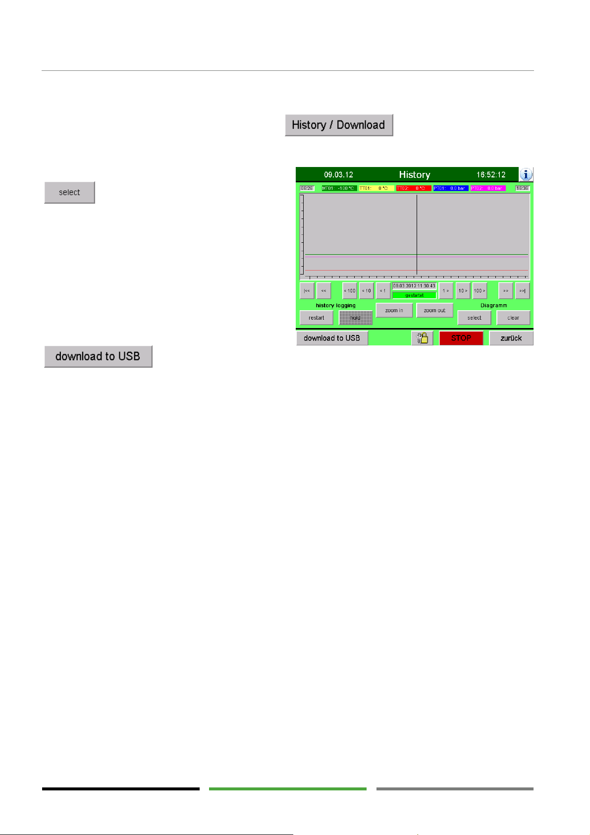
Operating elements
5.7.4 Download of data logging history
Via the menu window „data logging“ (→ page 40) and you get to the menu window
„History“. From here the graphs for the past two months can be displayed.
On the password level „operator“ you can press
to upload from the internal memory the
data package of the desired month. This operation
might require some time.
After uploading the data package you can navigate in
the graph as previously described for „data logging“
(→ page 40)
To download the data ot a USP stick press
. For a detailed description and advise please contact the manufacturer. (→ page 5).
The function field „history logging“ allow to stop (hold) or restart the data logging process. These function
fields are deactivated and can only be accessed on the password level „service“.
46
Page 47
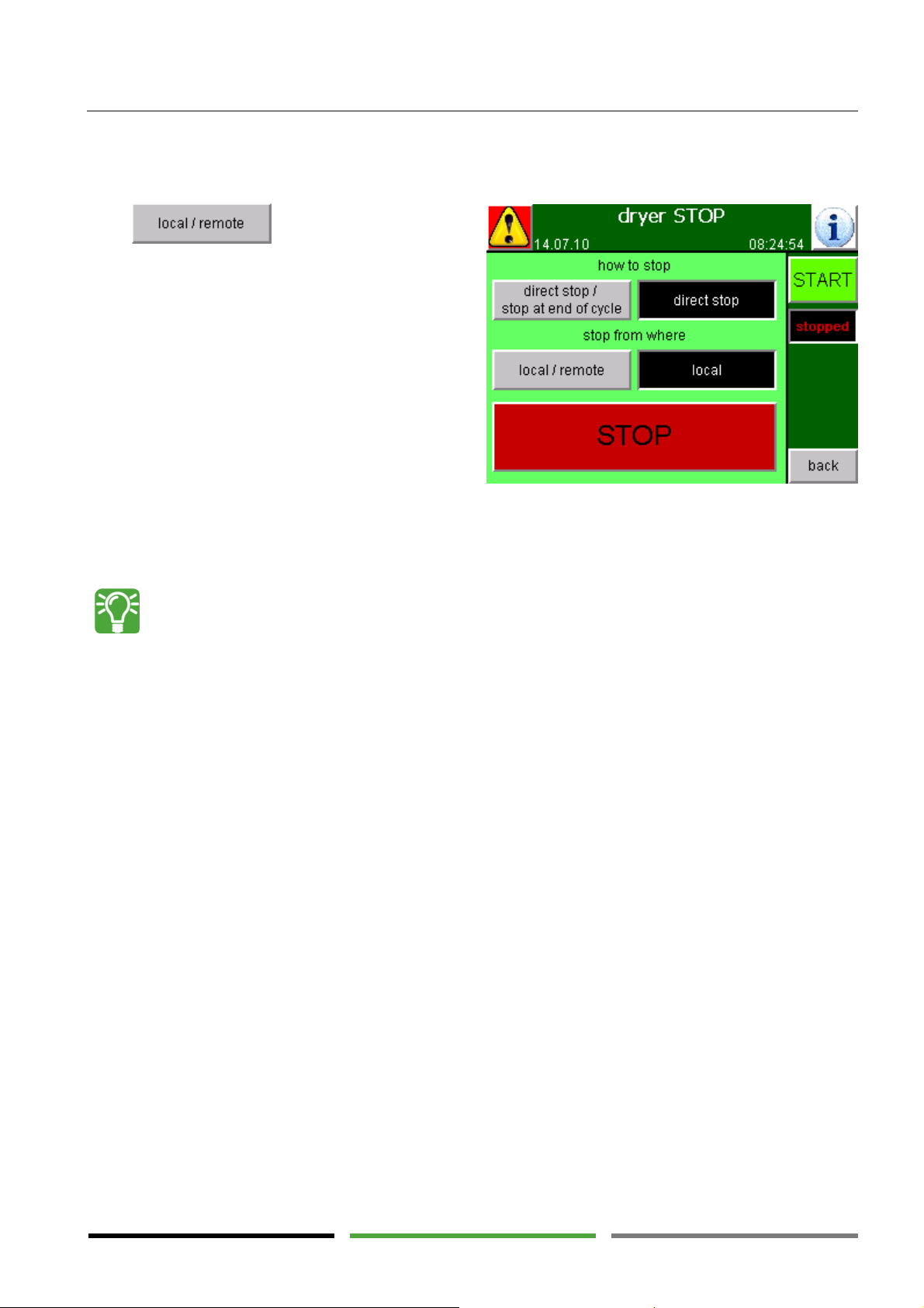
Operating elements
"Remote" ON/OFF control
5.7.5 Starting and stopping the dryer locally or remotely
On the "operator" password level remote ON/OFF control can be performed.
Press to change between the two
options. The adjacent black field indicates the currently selected operating mode.
In "remote" control a digital input in the control box of
the dryer is activated. The input can be operated by an
external signal.
For details on connecting the external signal, please
refer to the wiring diagram in the appendix.
If "remote" ON/OFF control is selected, starting and stopping the dryer via the control box is blocked. First,
ON/OFF control must be set to "local" again. Then the "Start" and "Stop" functions fields will be activated
again.
If, during no-load operation, there is no flow of compressed air through the dryer for a longer
time, the measured dew point value gradually becomes worse. This results in repeated vessel
switch-over and regeneration cycles although regeneration is not required. Even if the measured
dew point value remains on a good level, vessel switch-over and regeneration are started as soon
as the maximum time has elapsed. This type of operation unnecessarily consumes energy.
The "remote" function stops the unnecessary regeneration cycles.
Using an external signal the dryer program can be stopped during no-load operation.
If a compressor is directly assigned to a dryer, the load contact on the compressor can be used as
the external signal.
An optimum combination is as follows: "remote" and "stop at end of cycle".
5.8 Control system interfaces
Several interfaces in the control box enable signal exchange between the dryer and a higher-level control system. For details on the signal interfaces, please refer to the wiring diagram in the appendix.
Available signal outputs:
4...20 mA signal : Dew point
4...20 mA signal : Operating pressure
Digital signal : Common alarm
Digital signal : Common warning
Available signal inputs:
Digital signal : Remote ON/OFF
47
Page 48
Operating elements
DANGER !
– Electric voltage
CAUTION !
–
Qualification and experience required
No. Error message
Indicating sensor
Reaction of
Measure for restart
1 fault control voltage
Circuit breaker in control box
Program stopped
Check voltage
2 Alarm blower circuit
Motor circuit switch in control box
Program stopped
Check voltage
5.9 Error messages and measures
The dryer is operated at electric voltages up to 690 V.
Touching live parts may result in serious injury or death.
Work on electrical components must only be carried out by qualified and authorised personnel.
Use a voltage detector to make sure the dryer has been disconnected from the power supply and
that there are no live parts before starting maintenance work.
In the event of fire, do not extinguish the fire using water.
Persons working on and with the dryer have to be qualified personnel who, because of their qualification and experience, are familiar with handling compressed air systems and electrical systems.
If you are not experienced in using these systems, please ask the relevant experts for help. We
highly recommend that commissioning and maintenance be carried out by the manufacturer or
one of the authorised service partners.
The following tables indicate the possible reasons of the error messages and the dryer reaction to these errors.
In addition, measures for restarting the dryer are listed. Please note that measures in the control box or in
other electrical components must only be taken by qualified personnel.
In the event that error messages occur repeatedly, please contact the manufacturer or one of their service
partners. The number in the first column is useful for communication purposes.
Please note that often the reasons may only be clearly recognised when looking at several error messages
occurring simultaneously or consecutively. Please write down the time of the error messages listed consecutively as well as the operation messages listed during this time. (→ Page 41)
5.9.1 Error messages: alarms
24V
switch
Reason / event
Circuit breaker has triggered
Overvoltage
Short circuit
Open wire in signal loop
Alarm contact on motor circuit switch has
opened
Blower blocked or throttled
Blower runs in wrong direction
Overvoltage
Short circuit
Open wire in signal loop
control system
Blower= OFF
Heater = OFF
V4 and V5 = CLOSED
Blower= OFF
Heater = OFF
V4 and V5 = CLOSED
Release circuit breaker manually
Acknowledge message
Start up manually
Release motor circuit switch manually
Acknowledge message
Start up manually
Check regeneration air flow
Check direction of rotation of blower
(→ page 65)
Monitor blower
48
Page 49

Operating elements
No. Error message
Indicating sensor
Reaction of
Measure for restart
3 alarm heater limiter
TSH01 : limiter thermostat
Program stopped
Press release button manually
(→
4 runtime error valve
GS01 : final position switch
Program stopped
Check error reason and correct, if
5 runtime error valve
GS031 : final position switch
Program stopped
Check error reason and correct, if
6 alarm sensor loop
PT01 : pressure sensor
During expansion or
Check error reason and correct, if
7 alarm sensor loop
PT02 : pressure sensor
During expansion or
Check error reason and correct, if
8 alarm sensor loop
MT01 : dew point sensor
Program continues in
Check error reason and correct, if
9 alarm sensor loop
TT01 : temperature sensor
Program continues
Check error reason and correct, if
10 alarm sensor loop
TT02 : temperature sensor
Program continues
Check error reason and correct, if
11 operating pressure
PT01 or PT02 * : pressure sensor
Program cannot be
Compare pressure gauges PI01/PI02
switch
V1 / V2
V31
PT01
PT02
MT01
TT01
TT02
too low
Reason / event
Alarm contact on limiter thermostat opened
Regeneration air flow insufficient
Blower runs in wrong direction
Heater was stopped during heating phase
via "direct stop". (→ Page 31)
Open wire in signal loop
Valve runtime of 30 sec exceeded
Control pressure too low (→ page 5)
Wrong position of valve
Loose sensor
Loose sensor connector
Open wire in signal loop
Valve runtime of 30 sec exceeded
Control pressure too low (→ page 5)
Wrong position of valve
Loose sensor
Loose sensor connector
Open wire in signal loop
Loose sensor connector
Open wire in signal loop
Signal strength not within measuring range
Short circuit
Loose sensor connector
Open wire in signal loop
Signal strength not within measuring range
Short circuit
Loose sensor connector
Open wire in signal loop
Signal strength not within measuring range
Short circuit
Loose sensor connector
Open wire in signal loop
Signal strength not within measuring range
Short circuit
Loose sensor connector
Open wire in signal loop
Signal strength not within measuring range
Short circuit
Measured value below min. operation
pressure limit value (→ page 40)
control system
Blower= OFF
Heater = OFF
V4 and V5 = CLOSED
until final position is
reached
until final position is
reached
pressurisation
=> Program stopped
pressurisation
=> Program stopped
"fixed" cycle mode
and remains in
"fixed" cycle mode
In the event of open
wire indication = 850°C
and heater OFF
Heating is already
stopped after min.
heating time
In the event of open
wire indication = 850°C
Cooling is only
stopped after max.
cooling time
started
Program stops before
vessel switch-over
page 26)
Acknowledge message
Start up manually
Check direction of rotation of blower
(→ page 65)
Check regeneration air flow
Check valve position (→ page 27)
required
Program restarts automatically after
error correction
Acknowledge message
See "Checking the signal loop" adviso-
ry note at the end of this chapter
required
Program restarts automatically after
error correction
Acknowledge message
See "Checking the signal loop" adviso-
ry note at the end of this chapter
required
Program restarts automatically after
error correction (start-up with 2 min
delay)
Acknowledge message
required
Program restarts automatically after
error correction (start-up with 2 min
delay)
Acknowledge message
required
Acknowledge message
Variable cycle mode may need to be
reselected manually
required
Acknowledge message
required
Acknowledge message
to indication on display
Check error reason and correct, if
required
Program restarts automatically after
error correction (start-up with 2 min
delay)
Acknowledge message
49
Page 50

Operating elements
No. Error message
Indicating sensor
Reaction of
Measure for restart
12 pres. equal. for
PT01 and PT02 : pressure sensor
Program stops before
Compare pressure gauges PI01/PI02
13 Alarm monitoring
Loop valves
V61/V62:
limit switch
Program stops until
Check error reason and correct, if
14 max. expansion
PT01 or PT02 ** : pressure sensor
Program stopped
Compare pressure gauges PI01/PI02
15 void
16 automatic start
-
up
Control system
Program cannot be
Switch off control box via main circuit
17 void
18 pressure equalis
a-
PT01 and PT02 : pressure sensor
Program stopped
Compare pressure gauges PI01/PI02
19 fault Can Bus
Control system
Program stopped
Check error reason and correct, if
20 runtime error valve
GS032 : final position switch
Program stopped
Check error reason and correct, if
21 No recipe loaded!
Control system
Program stopped
Contact manufacturer or service
22 alarm has stopped
Control system
Reaction corresponds
Check error reason and correct, if
changeover not OK
loop valve V61/V62
(Only for option
“loop cooling”)
time exceeded
interrupted!
Reason / event
Max. tol. pressure equalisation limit value
exceeded ((→ page 38)
See also error message no. 18
30 sec valve run time exceeded
control pressure to low (→ page 28)
malposition of valve
sensor loose
plug of the sensor loose
broken wire in signal loop
Maximum expansion time min. time limit
reached and expansion pressu limit value still
exceeded (→ page 36)
Serious leakage to the inside
Valve V5 does not open
Valve V4 does not close
Expansion silencer X1 blocked
When starting up the control system…
... an ***error has been indicated
OR
... the dryer has been stopped
OR
... remote OFF has been triggered
control system
vessel switch-over
limit switch is reached
until limit value is
reached
started
to indication on display
Check error reason and correct, if
required
Program restarts automatically after
error correction (start-up with 2 min
delay)
Acknowledge message
required
Program restarts automatically after
error correction
Acknowledge message
See "Checking the signal loop" adviso-
ry note at the end of this chapter
to indication on display
Check for leaks and repair, if required
Check error reason and correct, if
required
Program restarts automatically after
error correction
Acknowledge message
See "Checking the signal loop" adviso-
ry note at the end of this chapter
breaker and back on after some seconds
Acknowledge message
Start up manually
tion not achieved
V32 (Only for dryer
type “DTS-BV”)
sequence
Maximum pressurisation time maximum
time limit reached and max. tol. pressure
equalisation limit value still exceeded (→ page
38)
Serious leakage to the outside (e.g. via RV1
or V31 (V32))
Valve V4 does not open
Valve V5 does not close
Connection physically interrupted
Valve runtime of 30 sec exceeded
Control pressure too low (→ page 5)
Wrong position of valve
Loose sensor
Loose sensor connector
Open wire in signal loop
No parameter recipe loaded to the control
system. Limit values and time limits are not
defined.
New software had been uploaded. There-
fore the recipe had been deleted and needs to
be uploaded again.
*** error recognised
until limit value is
reached
Blower= OFF
Heater = OFF
V4 and V5 = CLOSED
until final position is
reached
Blower= OFF
Heater = OFF
V4 and V5 = CLOSED
to the error present
to indication on display
Check for leaks and repair, if required
Check error reason and correct, if
required
Program restarts automatically after
error correction
Acknowledge message
See "Checking the signal loop" adviso-
ry note at the end of this chapter
required
Acknowledge message
Start up manually
required
Program restarts automatically after
error correction
Acknowledge message
See "Checking the signal loop" adviso-
ry note at the end of this chapter
partner. The correct recipe has to be
selected.
required
Acknowledge message
Start up manually
50
Page 51

Operating elements
No. Error message
Indicating sensor
Reaction of
Measure for restart
23 cycle time exceeded
Control system
Program continues
Switch off control box via main circuit
24 Pressure implaus
i-
PT01 or PT02 **
: pressure sensor
Program stopped
Compare pressure gauges PI01/PI02
25 error hardware
Control system
Program continues
Switch off control box via main circuit
No. Error message
Indicating sensor
Reaction of
Measure for
restart
101 manual operation
Control system
Manual operation has been selected on the
Program cannot be
Switch off manual operation
102 automatic sequence
GS031 :
final position switch
Valve was turned to wrong position (e.g.
Program cannot be
Check valve and correct position, if
103 heating temperature
TT01 : temperature sensor
Program continues
Continue to monitor the process
Check heating performance, if required
set reached during
104 heating end temp. not
TT02 : temperature sensor
limit value
set reached
Program continues
Continue to monitor the process
Check heating performance, if required
set reached during
No. Error message
Indicating sensor
Reaction of
Measure for restart
Reason / event
Internal PLC cycle check has negative result
ble
configuration
* = only the sensor on the "adsorbing vessel" is evaluated.
** = only the sensor on the "regenerating vessel" is evaluated.
*** = e.g. 24 V not present / CAN bus error / no recipe / implausible pressure / MCS blower
A pressure higher than 1 bar is present at
the "regenerating vessel".
Main valve V1/V2 was turned to wrong
position (e.g. during maintenance)
Pneumatic lines wrongly connected
See also No. 14
Hardware (I/O cards) was requested by
control system but not found
Control system
Blower= OFF
Heater = OFF
V4 and V5 = CLOSED
Program cannot be
started
until consequential
error occurs
breaker and back on after some seconds
Acknowledge message
Check hardware and replace, if re-
quired
to indication on display
Check valve and correct position, if
required
(only by service personnel) (→ page 27)
Check error reason and correct, if
required
Program restarts automatically after
error correction (start-up with 2 min
delay)
Acknowledge message
See "Checking the signal loop" adviso-
ry note at the end of this chapter
breaker and back on after some seconds
Acknowledge message
Start up manually
Check hardware and replace, if re-
quired
5.9.2 Error messages: warnings
Reason / event
ON
start with V31 open
not reached
reached
"service" password level
Final position reports open valve
during maintenance)
Pneumatic lines wrongly connected
See also message no. 5
Preselected control temp. limit value not
exceeded
AND
Control time limit set reached
(→ Page 37)
Heating performance inadequate
No regeneration air flow
Preselected end temperature
not exceeded
AND
Fixed or variable heating time
(→ page 37)
Heating performance inadequate
Regeneration air flow inadequate
Control system
started
started
(only by service personnel)
required
(only by service personnel) (→ page 27)
(is control temp.
heating process?) (→ Page 37)
Check fuses in the control box
Check current strength of heater
Check regeneration air flow
Check other error messages, if required
(is control temp.
heating process?) (→ Page 37)
Check fuses in the control box
Check current strength of heater
Check regeneration air flow
Check other error messages, if required
51
Page 52

Operating elements
Reason / event
Control system
105 cooling end temp. not
TT02
(TT01)
: temperature sensor
limit value
Program continues
Continue to monitor the process
Check other error messages, if required
106 automatic sequence
(Only for dryer type
GS032 : final position switch
Valve was turned to wrong position (e.g.
Program cannot be
Check valve and correct position, if
107 please close valve V3
! GS031 /
GS032
: final position switch
Valve was turned to wrong position (e.g.
Program cannot be
Check valve and correct position, if
108 expansion time min.
PT01, PT02 ** : pressure sensor
value has
Program continues
No measures required
109 pressurisation time
PT01, PT02 ** : pressure sensor
Program continues
No measures required
110 sequence stopped
Control system
Program stopped
Start up manually
111 dew point too high
MT01 : dew point sensor
e
Error no. 104 or no. 105 has been reported
Dryer overload due to excessive entry
Inadequate regeneration due to excessive
Condensate entry into the dryer due to
not reached during heating
Program continues
Usually, this error message is a cons
e-
Check sensor calibration (calibration
Check desiccant for contamination and
112 alarm vessel change
o-
PT01, PT02 : pressure sensor
limit value
min. operation
Program stopped
Compare pressure gauges PI01/PI02 to
Check error reason and remove, if
Program restarts automatically after
113 cooling temperature
TT02
TT01 : temperature sensor
page
Program continues
Continue to monitor the process
No. Error message
Indicating sensor
Reaction of
Measure for
restart
reached
start with V32 open
“DTS-BV”)
has been set
min. has been set
ver 1/2
too high
Preselected end temperature
not exceeded
AND
Max. cooling time limit reached
(→ Page 38)
Ambient conditions too high (→ page 11)
Regeneration air flow inadequate
Final position reports open valve
during maintenance)
Pneumatic line mixed up
See also message no. 5
Final position reports open valve
during maintenance)
Pneumatic line mixed up
An invalid expansion time min.
been entered and reset automatically
(for service possible only)
An invalid pressurisation time minimum
value has been entered and reset automatically
(for service possible only)
Program was stopped
Dew point limit value exceeded (→ pag
39)
Previous error
previously
conditions (→ page 11)
ambient conditions (→ page 11)
Measuring error of dew point sensor
defective pre-filtration
Contaminated or aged desiccant
Control temp.
(→ page 37)
See also "Pre-dried compressed air" adviso-
ry note (→ page 9)
Max. tol. pressure equalisation
exceeded ((→ page 38)
See also error no. 18
Measured value below
pressure limit value (→ page 40)
See also error no. 11
Error in sensor loop PT01, PT02
See also errors no. 6 and no. 7
Control temp. limit value exceeded (→
38)
Ambient conditions too high (→ page 11)
No regeneration air flow
started
started
Check regeneration air flow
Check ambient temperature and mois-
ture at regeneration gas inlet
required
(only by service personnel) (→ page 27)
required
(only by service personnel) (→ page 27)
quential error.
Check previous error messages
Check compressed air entry conditions
Check ambient conditions
once a year is recommended)
Check filter upstream of dryer
replace, if required
Check heating parameters
Continue to monitor the process
indication on display
required
error removal (start-up with 2 min delay)
Acknowledge message
Check regeneration air flow
Check ambient temperature at regen-
eration gas inlet
Check other error messages, if present
52
Page 53

Operating elements
Reason / event
Control system
114 expansion can't be
PT01, PT02 ** : pressure sensor
Program stopped
until signal returns and
Check signal from pressure sensor and
Program restarts automatically after
115 pressurisation can't be
PT01, PT02 ** : pressure sensor
Program stopped
until signal returns and
Check signal from pressure sensor and
Program restarts automatically after
116 Fault communication
Bus-Gatway :
inside dryer control panel
Program continues
Check the communication with the
117 Expansion pressure has
Input to control menu:
Program continues
No measures required
118 Service required
Dryer control:
the counter of operating hours has reached
Program continues
Contact manufacturer or service par
t-
Checking the signal loop
finished
finished
CAN-DP coupler
been set
* = only the sensor on the "adsorbing vessel" is evaluated.
** = only the sensor on the "regenerating vessel" is evaluated.
Error in sensor loop PT01, PT02
Error in sensor loop PT01, PT02
The connection from the dryer control to
the bus-gatewas ist disturbed
a dangerous value has been selected and
has automatically been corrected by the
control.
the counter of operating hours has reached
the limit value service interval
the limit value service reminder
A valve not moving to the correct position is often caused by an interruption of the signal loop
controlling the valve and not by the valve itself. For troubleshooting, please check each step within the signal loop:
1) Check the valve position (→ page 27).
2) Check the desired state of the valve in the "status" menu window (→ page 35).
3) Check the LED on the output card of the control system.
4) Check the LED on the pilot valve terminal.
5) Check the control pressure signal for the valve actuator.
limit value is reached
limit value is reached
remove error, if required
error removal
remove error, if required
error removal
master control
Check gateway hardware
ner for manintenance.
53
Page 54
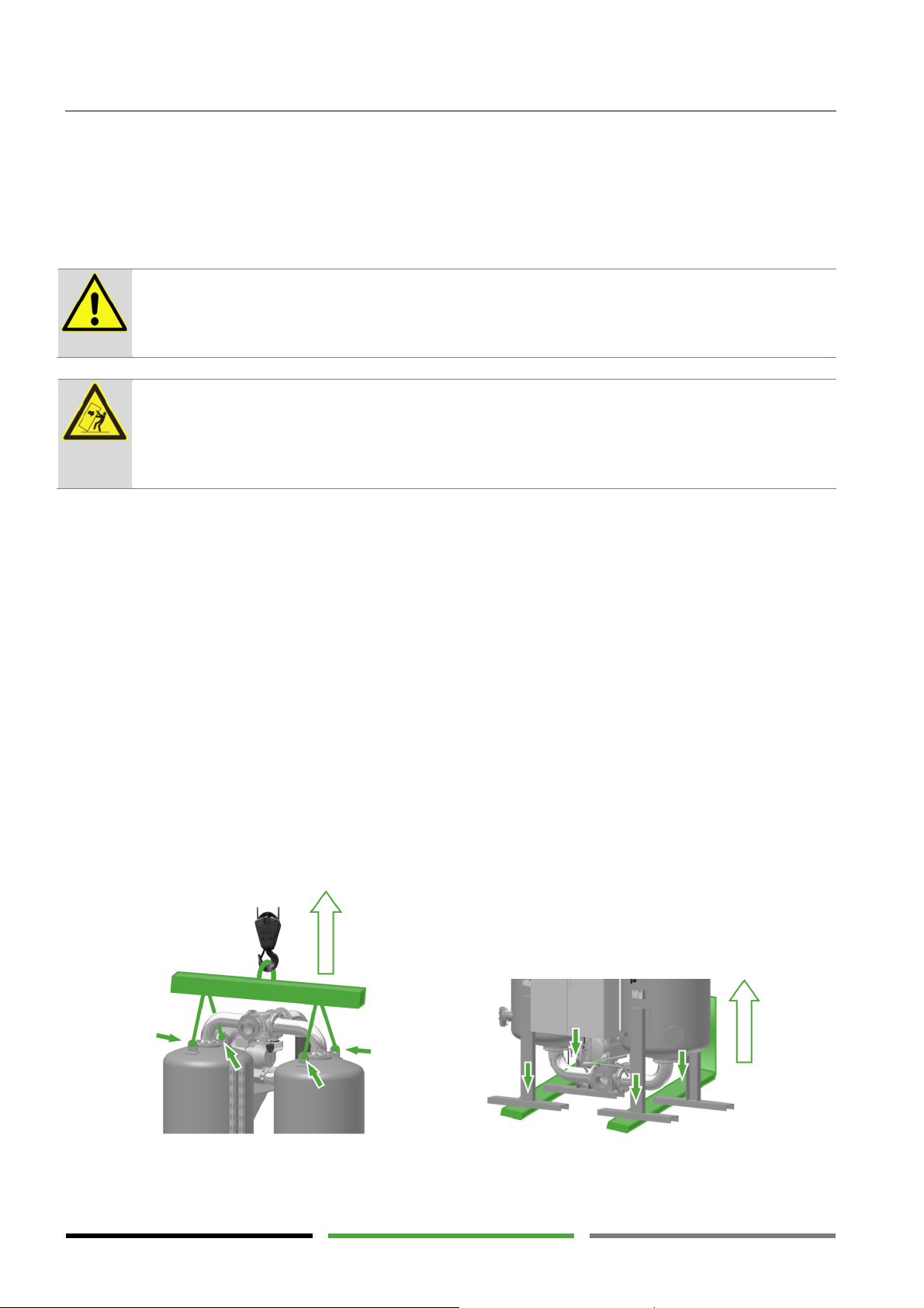
Transportation, setting up and storage
DANGER !
– Damage
DANGER !
– Risk of tilting
6. Transportation, setting up and storage
6.1 Transportation
Damages of the dryer may lead to unpredictable hazardous situations.
Operating a damaged dryer may result in serious injury or death.
Never start to operate a damaged dryer.
The centre of gravity is in the upper part of the dryer.
Tilting of the dryer may result in serious injury or death.
During transport and during loading and unloading secure the dryer against tilting using the lifting
lugs.
Although great care is taken damages caused by transportation cannot be ruled out. Therefore, always check
the dryer for possible damages after transportation and packaging removal.
The haulage contractor and the manufacturer or the sales partner must immediately be informed about any
damage.
Make sure to provide adequate lifting equipment when transporting and loading or unloading the
dryer.
Persons responsible for transportation must be appropriately qualified.
The dryer must only be lifted at the appropriate points using lifting equipment. (Transport pallet;
base frame; support feet; lifting lugs at the top of the vessel) (→ see Figure).
Transport the dryer in upright position. Horizontal transportation may lead to mixing of the differ-
ent desiccant layers thus causing malfunctions. Please contact the manufacturer first if the dryer
needs to be tilted for transportation.
Take the dryer weight and the maximum allowable load of the lifting and transport equipment used
into account.
Do not remove the packaging material until the dryer is moved to its final place of installation.
The national regulations for accident prevention must be adhered to.
54
Page 55
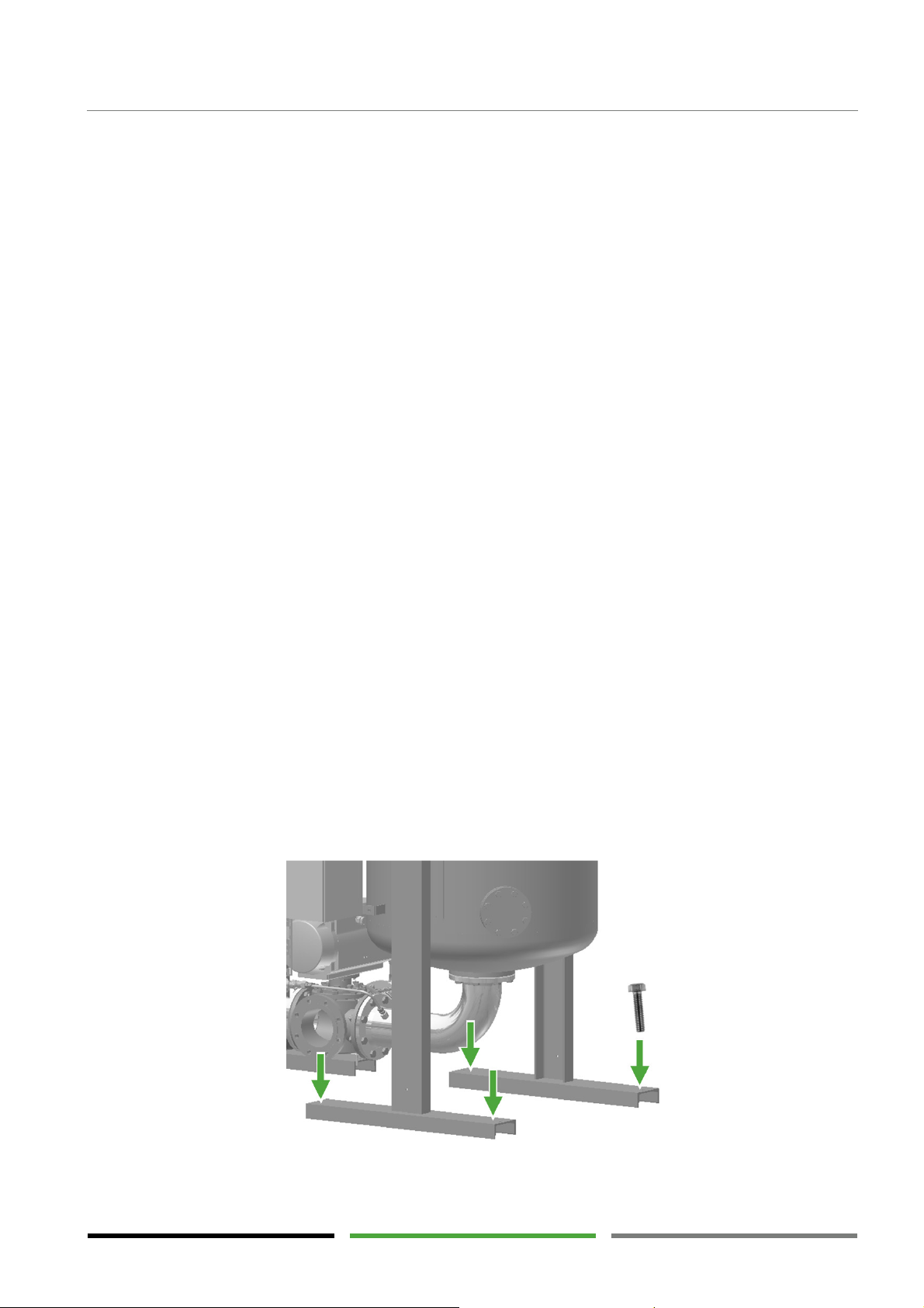
Transportation, setting up and storage
6.2 Setting up
Please refer to section "Description of application" (→ page 9). Here, you will find a list of requirements on the
installation site.
Important data of the dryer can be found in section "Technical data" (→ page 11).
Additional requirements on the installation site:
The ground for dryer installation must be level and capable to carry heavy loads. Ground irregulari-
ties must be levelled in order for tensional forces not to occur in the piping of the dryer. When calculating the total weight, please take the additional load during a hydrostatic pressure test into account. The volume information on the vessel helps when calculating the additional weight.
Because of noise emissions the installation site should not be in the vicinity of stationary workplac-
es.
Keep a service distance to walls and other systems around the dryer of 1 m, minimum.
During maintenance of the dryer components lifting equipment with adequate load capacity should
be available and access of this equipment to the dryer must be ensured.
The place of installation should not be in the vicinity of hallways in order to avoid risks to inexperi-
enced persons.
Set up the dryer such that the pressure gauge and the control system are clearly visible and can be
operated properly.
We recommend anchoring the dryer into the ground using the holes in the vessel supports.
55
Page 56

Transportation, setting up and storage
CAUTION !
– Moisture in electrical components
6.3 Storage
To maintain the dryer quality the dryer must be stored at a suitable location and properly prepared for storage.
The place of storage has to fulfil the following requirements:
Indoors
Protected against weather impact
Frost-free
Dry
If the dryer is to be stored immediately after delivery, it must only be protected against dust using an additional cover.
If the dryer has already been used for drying compressed air, please proceed as follows:
1) Disconnect the compressed air flow from the dryer.
2) Perform a regeneration procedure for each vessel without compressed air flowing through the dry-
er. This ensures the dryer to be stored with dry vessels.
3) Decommission the dryer. (→ Page 67)
4) Depressurise the dryer. (→ Page 68)
5) Disconnect the dryer from the electrical supply.
6) Disconnect the dryer from the compressed air system.
7) Close the inlets and outlets of the dryer using flange covers.
8) Place a desiccant bag in the control box and in the junction box of the heater.
9) Protect the dryer against dust using a cover.
To recommission the dryer after storage, please proceed as described for initial commissioning. (→ Page 61)
Long-term storage may lead to penetration of moisture into electrical components. This may result
in short circuits or damages to these components.
Check the electrical dryer components for internal moisture.
The necessary actions must only be performed by a qualified electrician.
Prior to commissioning an insulation resistance test must be carried out on the electric heater
and on the blower motor.
The insulation resistance to earth and between the individual phases must be checked.
At a test voltage of 500 V the insulation resistance must not be below 25 kΩ.
In the event the insulation resistance is too low, measures for drying the components must be
taken. Please contact the manufacturer or one of the service partners.
56
Page 57
DANGER !
– Overload
CAUTION !
– Hot exhaust air flow
DANGER !
–
Bursting components due to external forces
DANGER !
– Overpressure
7. Installation
7.1 Installing the connecting pipelines
The dryer is under pressure.
Suddenly escaping compressed air may result in serious injury.
Do not carry out mechanical or electrical work on the dryer as long as the dryer is under pressure.
The dryer must only be operated with compressed air within the maximum allowable operating
conditions. The operating conditions are defined on the type plate (→ page 13).
Exceeding the maximum allowable operating conditions may result in serious injury or death.
It is the duty of the operator to ensure that the connected pressure source is safe-guarded such
that the maximum allowable operating pressure (PS) and the maximum allowable temperature
(TS) are not exceeded.
Please also refer to section “Intended use” (→ page 9).
Installation
Proper installation is required for safe and error-free operation of the dryer.
Please observe the following steps when installing the compressed air pipeline (4) + (6):
Hot air escapes from the regeneration air outlet. The surface of the exhaust air duct may reach
temperatures above 150°C. Unprotected touching of this surface may cause burns.
The installation room temperature will rise when not using an exhaust air duct.
Install an exhaust air duct out of reach of persons.
The dryer components are not designed for externally applied forces and may burst due to additional load impact.
Bursting, pressure-bearing components may result in serious injury or death.
The support required for the connected pipelines has to be provided by the customer. Transmission of loads or stress into the connection flanges of the dryer is not permissible.
Make sure that the dryer and the compressed air system are free from pressure. If the compressed
air system has to remain under pressure during installation, the shut-off valves have to be protected against unintentional opening. (2) + (8)
The compressed air source (1) (e.g. compressor) must be safe-guarded against exceeding of the
maximum allowable operating pressure using safety equipment.
The compressed air pipelines must be provided with shut-off valves used for disconnecting the dry-
er from the piping system (2) + (8). We recommend using shut-off valves with continuous opening
behaviour (e.g. shut-off valves with gear hand wheel). This behaviour avoids sudden pressure
equalisation between the piping sections.
We recommend using a bypass line (11) around the dryer.
The pipelines must be suitable for use with the maximum possible operating pressure.
57
Page 58

Installation
The take-over points (flanges) have to be compatible to the dryer inlet and outlet with regard to
nominal width, nominal pressure and type. (→ See general arrangement drawing in the appendix)
Any vibrations or pulsation must not be transmitted to the dryer via the piping. This may damage
the desiccant, the dryer control system or other components. If required, install compensators or
pulsation absorbers in the pipelines to be connected.
Wet pipelines upstream of the dryer (4) should be installed at a slope in order for condensate (wa-
ter and oil) in the line to be discharged in flow direction. If installation of an upright pipeline is inevitable, a condensate drain must be provided at the lowest point of the pipeline. This avoids condensate from being accumulated in the pipeline and suddenly being swept away by the compressed air
flow. These kinds of water shocks may damage the filter and dryer and must be avoided.
Prior to closing the connected pipelines, please check that there are no objects or contaminations
left in the pipelines.
Remove the end caps from the dryer inlet and outlet.
When checking the installation for leaks the maximum allowable operating pressure of the dryer
must not be exceeded. (→ See specification on the type plate, page 13)
Never fill the dryer with water when performing a pressure test. Liquids will destroy the desiccant!
Please observe the following steps when installing the exhaust air duct (14):
The nominal width of the exhaust air duct (15) should be at least the nominal width of the com-
pressed air connections (GJ/GO).
The exhaust air ranges from warm and humid to hot. An aggressive condensate may be produced in
longer exhaust air ducts. Use corrosion-resistant materials. Install the exhaust air ducts at a slight
slope towards the outlet (16). If required, a condensate drain must be provided at the lowest point
of the exhaust air duct.
The exhaust air duct (15) must not throttle the exhaust air flow. Reduced regeneration volume flow
results in slow and sometimes inadequate regeneration. This may lead to reduced dryer performance and damage of the desiccant. Make sure that the pressure loss is low when designing the
exhaust air duct. The pressure loss in the exhaust air duct must not exceed 20 mbar.
The end of the exhaust air duct (16) must be installed such that rain may not enter the duct.
The exhaust air duct (15) will become very hot. Install the exhaust air duct out of reach of persons.
As an alternative, the exhaust air duct may be provided with a thermal insulation.
Make sure that the outlet (16) of the exhaust air duct is installed in such a way that persons are not
at risk and will not be affected.
Install a protection grid against small animals on the outlet of the exhaust air duct (16).
Usually, the regeneration air is drawn in from the environment directly on the dryer. If the ambient air at the
place of installation contains dust, moisture or aggressive contamination, the regeneration air must be drawn
in from the outside or a clean place, respectably. For this purpose an intake nozzle (17) can be provided on the
dryer. (See section "Options" page 24)
Please observe the following steps when installing the intake duct:
58
The nominal width of the intake duct (18) should be at least the nominal width of the compressed
air connections (GJ/GO).
Page 59
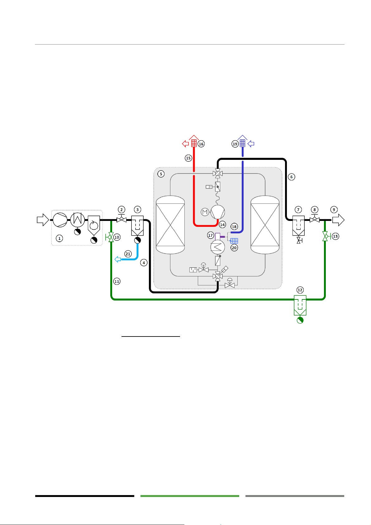
1 Compressed air supply
with water separator
12
Bypass filter with condensate drain
2 Valve at compressed air inlet
(gradually ope
n-
13 Bypass valve at outlet
3 Pre-filter with condensate drain
14
Exhaust air outlet on blower
4 Compressed air pipeline at inlet
15
Exhaust air duct
5
6 Dryer
16 Exhaust air outlet with bird protection grid
7 After
-
filter
with manual drain
17
Intake nozzle for regeneration air (option)
8 Valve at compressed air outlet
18
Intake duct
(if required)
9 Compressed air outlet
19
Regeneration
air inlet with bird protection grid
10 Bypass valve at inlet
20
Intake filter for regeneration air (option)
11 Bypass line
21
Conden
sate line
The intake duct (18) must not throttle the exhaust air flow. The sum of the pressure loss in the in-
take duct and exhaust air duct must not exceed 20 mbar.
The end of the exhaust air duct must be installed such that rain may not enter the duct. (19)
Install a bird protection grid on the outlet of the exhaust air duct. (19)
Make sure that the end of the exhaust air duct and of the intake duct is installed in such a way that
exhaust air (16) cannot flow back in the intake duct (19).
Installation example
Installation
ing)
Compressed air pipeline at outlet
Please note that the scope of supply only comprises the dryer (5). Items (3), (7), (12) and (17) can be purchased optionally. All the other items have to be provided by the customer.
and rain protection
and rain protection
59
Page 60
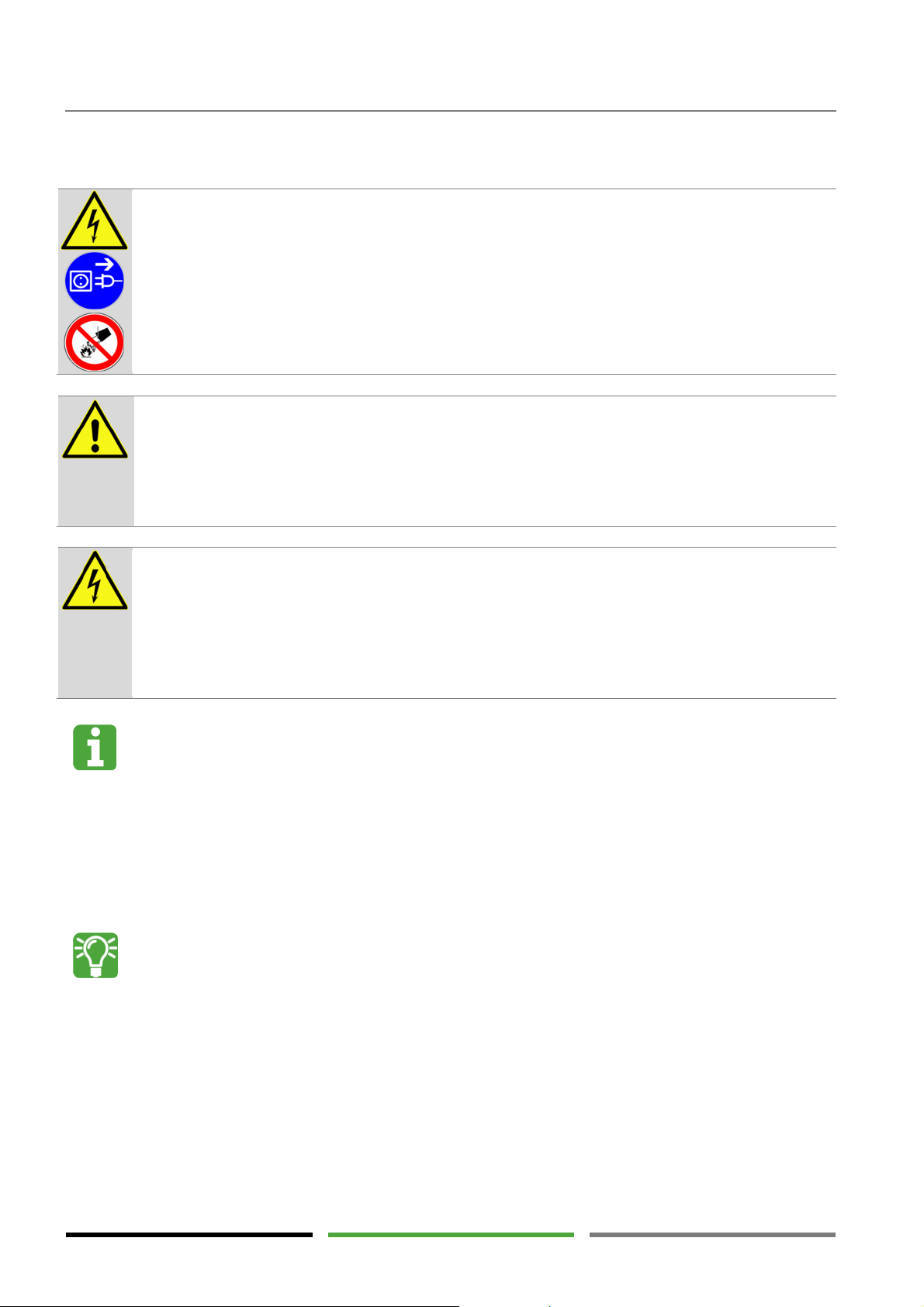
Installation
DANGER !
–
Electric voltage
CAUTION !
– Qualification and experience required
DANGER !
– Moisture and contamination in electrical components
Qualified electrician required
Communication interfaces
7.2 Installing the power supply
The dryer is operated at electric voltages up to 690 V.
Touching live parts may result in serious injury or death.
Work on electrical components must only be carried out by qualified and authorised personnel.
Use a voltage detector to make sure the dryer has been disconnected from the power supply and
that there are no live parts before starting maintenance work.
In the event of fire, do not extinguish the fire using water.
Persons working on and with the dryer have to be qualified personnel who, because of their qualification and experience, are familiar with handling compressed air systems and electrical systems.
If you are not experienced in using these systems, please ask the relevant experts for help. We
highly recommend that commissioning and maintenance be carried out by the manufacturer or
one of the authorised service partners.
Moisture and contamination in electrical components may lead to damages resulting in unpredictable dangers for the operating personnel. As a consequence, short circuits and faulty circuits may
occur.
Always keep the control box and the terminal box dry and free from contamination and foreign
bodies.
Make sure the control box and the terminal box are securely closed during operation.
Electrical connection of the dryer must only be carried out by a qualified electrician who is familiar
with reading electro-technical documentation.
The dryer is supplied centrally with voltage via one connection point in the control box. All the internal control
voltages are produced in the control box using transformers.
For the data required for connecting and securing the voltage supply, please refer to the wiring diagram (→
see appendix: wiring diagram – page: "cover sheet 2" (top left) and page: "power supply).
The dryer is provided with different signal inputs and outputs for dryer control and dryer monitoring. These communication interfaces are used to implement improved monitoring and economical
operation of the dryer. For the interfaces, please refer to the wiring diagram ( → see appendix).
Please also see section "Control system interfaces" (→ page 47).
60
Page 61

Commissioning
CAUTION !
–
Qualification and experience required
8. Commissioning
Persons working on and with the dryer have to be qualified personnel who, because of their qualification and experience, are familiar with handling compressed air systems and electrical systems.
If you are not experienced in using these systems, please ask the relevant experts for help. We
highly recommend that commissioning and maintenance be carried out by the manufacturer or
one of the authorised service partners.
8.1 Requirements for initial commissioning
All the requirements for unhindered commissioning must be fulfilled, especially when commissioning is carried
out by external qualified personal.
Make sure the following requirements for initial commissioning have been fulfilled:
External qualified personnel have been informed about the commissioning date in good time (2
weeks in advance, minimum).
External qualified personnel have been informed about the following in good time: special local
conditions; site-specific safety guidelines; required safety instructions, if necessary; specially required qualifications, if necessary; special personal protective equipment.
The place of installation can be freely accessed and entered without any risks.
Neighbouring construction sites do not affect commissioning.
The dryer is connected to the compressed air system using pipelines. (→ Page 57)
The dryer is connected electrically and voltage supply is ensured.
(→ Page 60)
The compressor is ready to operate and personnel for starting and operating the compressor are
present.
Compressed air can be delivered to the downstream system. A volume flow rate of at least 40% of
the nominal dryer performance can be led through the dryer.
The dryer is classified pressure equipment (see declaration of conformity in the appendix). Prior to
commissioning the dryer has to be approved by the local authorities according to the applicable national regulations. In the EU, the Pressure Equipment Directive 97/23/EC has to be observed.
Please check the following directly before commissioning:
The operating limits must not be exceeded. (→ Page 9)
The main circuit breaker is set to "0-OFF" and the control box is disconnected from the voltage sup-
ply. (→ Page 26)
The shut-off valves provided by the customer and located upstream and downstream of the dryer
are closed.
The connections may have become loose due to dryer transportation. Make sure the piping con-
nections, screwed joints and pneumatic lines are tightly secured. Tighten loose connections using
the appropriate tools.
Make sure the cable clamps in the control box are tightly secured. Tighten all the screw connections
using the appropriate tools.
61
Page 62

Commissioning
CAUTION
! – Moisture in electrical components
Check all the components for visible damages. If there are defective components, commissioning of
the dryer is not permitted.
Long storage may lead to penetration of moisture into electrical components. This may result in
short circuits or damages to these components.
Check the electrical dryer components for internal moisture.
The necessary actions must only be performed by a qualified electrician.
Prior to commissioning an insulation resistance test must be carried out on the electric heater
and on the blower motor.
The insulation resistance to earth and between the individual phases must be checked.
At a test voltage of 500 V the insulation resistance must not be below 25 kΩ.
In the event the insulation resistance is too low, measures for drying the components must be
taken. Please contact the manufacturer or one of the service partners.
62
Page 63
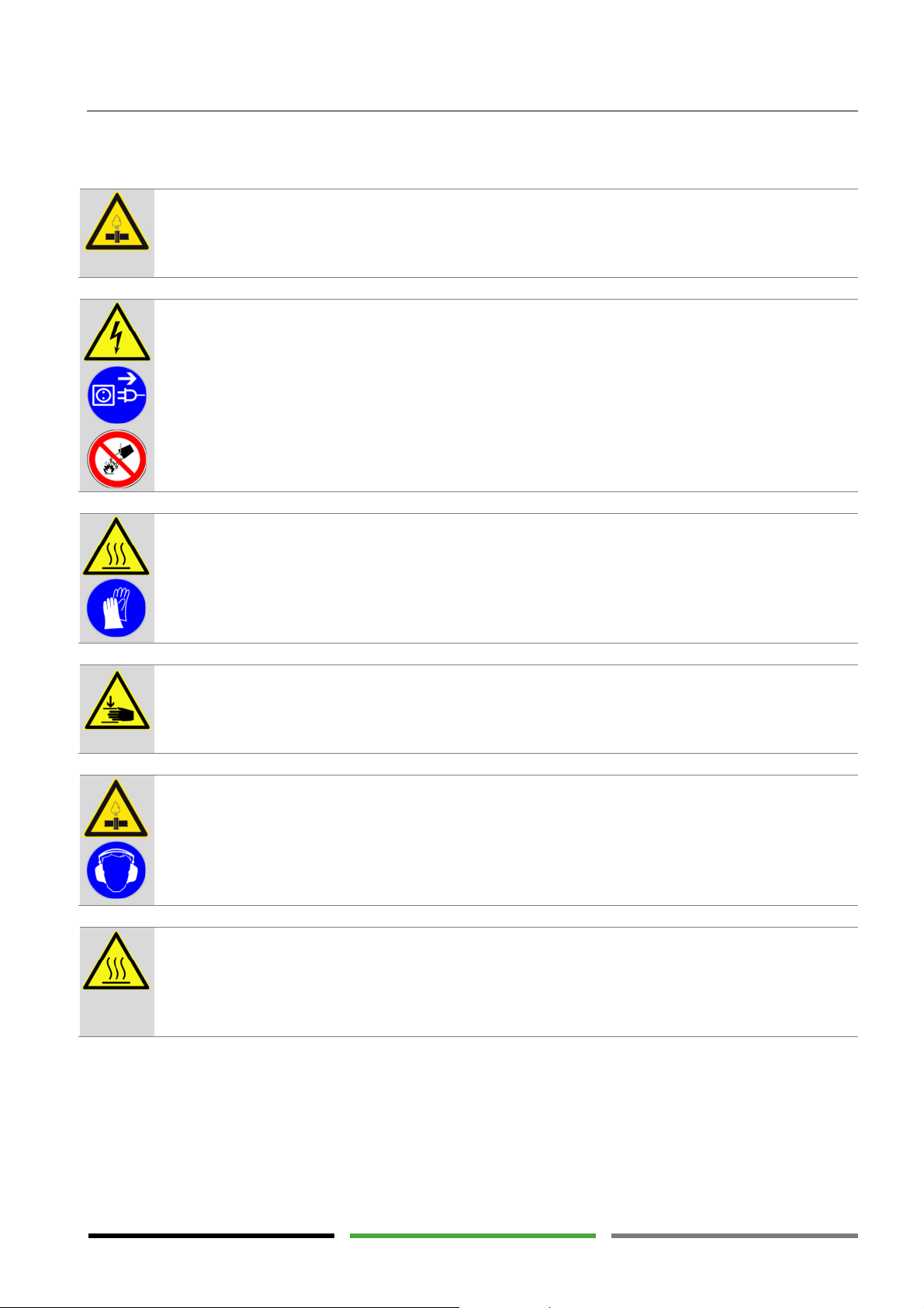
DANGER !
– Overpressure
DANGER !
– Electric voltage (2;6;8)
WARNING !
– Hot surfaces
WARNING !
– Risk of crushing
WARNING !
–
Suddenly escaping pressure
CAUTION !
– Hot exhaust air flow
8.2 Starting the dryer
The dryer is under pressure.
Suddenly escaping compressed air may result in serious injury.
Do not carry out mechanical or electrical work on the dryer as long as the dryer is under pressure.
Commissioning
The dryer is operated at electric voltages up to 690 V.
Touching live parts may result in serious injury or death.
Work on electrical components must only be carried out by qualified and authorised personnel.
Use a voltage detector to make sure the dryer has been disconnected from the power supply and
that there are no live parts before starting maintenance work.
In the event of fire, do not extinguish the fire using water.
The surfaces of the vessels and pipes may reach temperatures above 150°C.
Unprotected touching of this surface may cause burns.
Avoid direct contact to these surfaces. Restrict access to the surfaces, if necessary, or install thermal insulation on the hot components. (→ Page 24)
Never store inflammable parts and material in the vicinity of the dryer.
The cardan shaft will automatically turn by 90° approximately every 6 hours. Touching the cardan
shaft may cause parts of the body to be injured or twisted.
Do not hold on to the cardan shaft. Do not put your hand into the link joint of the cardan shaft.
If all conditions required for commissioning are fulfilled, the commissioning procedure can be started. Perform
the following steps in the listed order.
The dryer is depressurised approximately every 6 hours using a silencer. A loud and strong airstream may carry small particles and cause injury.
Do not place any equipment in the vicinity of the silencer. The silencer must not be manipulated or
removed. Always wear hearing protectors when working in the vicinity of the dryer.
Hot air escapes from the regeneration air outlet. The surface of the exhaust air duct may reach
temperatures above 150°C. Unprotected touching of this surface may cause burns.
The installation room temperature will rise when not using an exhaust air duct.
Install an exhaust air duct out of reach of persons.
63
Page 64

Commissioning
CAUTION !
– Pressure blows and overload
Automatic start
-
up device
8.2.1 Pressurisation of the dryer
Rapid opening of the valves may cause pressure blows and increased flow rates in the dryer. Pressure blows and increased flow rates may lead to damages of the dryer.
Open the valves very slowly and make sure that the flow noise does not become too loud. Pay
special attention when opening valves that can be opened rapidly by means of a pivoting movement.
The dryer valves are controlled by compressed air which is supplied from inside the dryer. For this reason the
first requirement for commissioning is reaching a minimum pressure of 4 bar in the dryer. Pressurise the dryer
as follows:
1) Make sure the pressure gauges and pressure sensors are connected to the vessels. (→ Page 27)
2) Make sure the compressed air system upstream of the dryer inlet is under pressure. If necessary,
the compressor must be started.
3) Open the valve upstream of the dryer inlet very slowly until hearing the first clear flow noise. Stop
the procedure when the flow noise becomes loud.
4) Observe the vessel pressure gauges. Pressurisation can be monitored on one of the two pressure
gauges. Make sure the pressure is only rising slowly. Pressurisation speed may not exceed 2
bar/min.
5) Check the system for leaks during pressurisation. In the event of leaks, pressurisation must be
stopped and the leaks must be repaired. To repair the leaks the dryer has to be depressurised
again. (→ Page 68)
6) If flow noise and a pressure increase is no longer present when further opening the valve, it can be
opened completely.
8.2.2 Opening the outlet valve
Special attention must be paid if the compressed air system downstream of the dryer is free from pressure.
1) Open the valve downstream of the dryer outlet very slowly until hearing the first clear flow noise.
2) Observe the vessel pressure gauges. Make sure there is no sudden pressure drop in the vessel. The
vessel pressure may not drop for more than 1 bar.
3) If flow noise is no longer present when further opening the valve, it can be opened completely.
4) Air can now freely flow through the dryer. If a volume flow is to be transferred via the dryer, com-
missioning should be performed quickly or the valve downstream of the dryer outlet should be
closed again, in order for the dryer not to be overladen with moisture during standstill.
In the event the dryer is frequently started against a pressureless compressed air system, we recommend using an automatic start-up device. (→ Page 24)
The automatic start-up device prevents pressure blows and increased flow speeds from occurring
even when the compressor is started automatically.
64
Page 65
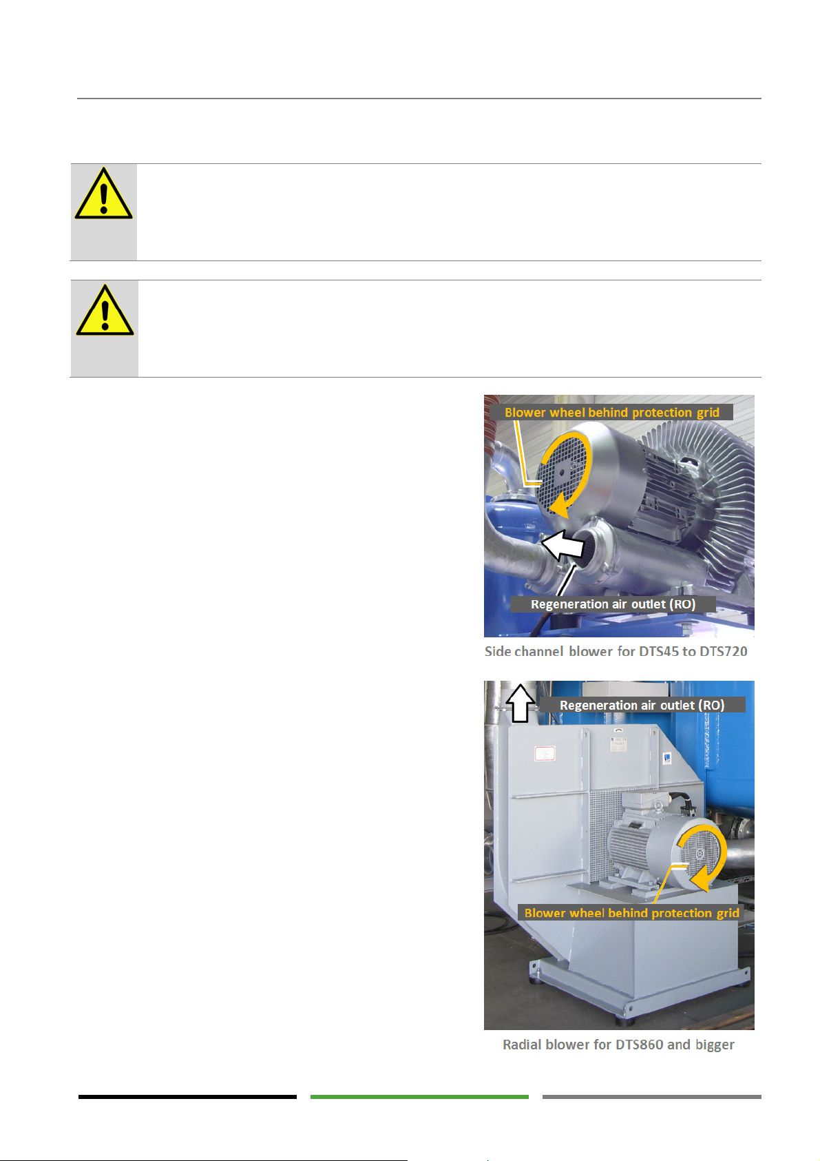
WARNING !
– Solid particles in outgoing regeneration air
CAUTION
! Damage of the motor because of overheating
8.2.3 Checking the direction of rotation of the blower
During blower operation solid particles may be expelled from the regeneration air outlet on the
blower. There is a risk of eye and skin injuries as long as the exhaust air duct has not been installed.
Never look into the regeneration air outlet during blower operation.
A) Make sure that the motor fan can draw sufficient cooling air. Don‘t block the protection grid
of the fan with e.g. insulation, tarpaulin, etc.
B) Avoid an overheating of the motor due to repeated start-ups.
The maximum number of motor start-ups shall be limited to 3 per hour.
The blower motor is supplied with current from three phases
(L1, L2, L3). Depending on the sequence of the phases, the
motor either rotates right or left. If the motor rotates in the
wrong direction, regeneration cannot be performed and the
electric heater may be damaged.
Commissioning
Check the blower for the correct direction of rotation as
shown in the figure:
1) Prior to starting, please read the following action
steps and section "Starting and stopping the dryer
control system" (→ page 31).
The steps will have to be carried out quickly one after the other to be able to stop the program again
rapidly when the motor rotates in the wrong direction. If the blower rotates in the wrong direction
for some time, the electric heater may be overheated and damaged.
2) Set the main circuit breaker to the "I-ON" position.
(→ Page 26)
The initialisation sequence runs on the touch panel
until the main menu is shown.
3) Start up the dryer as described in section "Starting
and stopping the dryer control system".
Depending on the phase in which the dryer was
stopped previously, it may take some minutes until
the dryer is in the heating phase and the blower
starts running.
4) As soon as the blower starts running immediately
stop the dryer program as described in section
"Starting and stopping the dryer control system".
The blower will continue to run for some seconds
65
Page 66
Commissioning
DANGER !
– Electric voltage (2;6;8)
until the dryer control system switches off the blower.
5) Take a look at the blower wheel of the motor. If the blower wheel rotates in the direction shown in
the figure, commissioning can be continued. If the blower wheel rotates in the wrong direction, the
following steps need to be carried out.
8.2.4 Correcting the direction of rotation of the blower
If the blower wheel rotates in the direction shown in the figure, commissioning can be continued.
The dryer is operated at electric voltages up to 690 V.
Touching live parts may result in serious injury or death.
Work on electrical components must only be carried out by qualified and authorised personnel.
Use a voltage detector to make sure the dryer has been disconnected from the power supply and
that there are no live parts before starting maintenance work.
In the event of fire, do not extinguish the fire using water.
1) Set the main circuit breaker to the "0-OFF" position and secure it against unintentional reclosing.
(→ Page 26)
2) Exchange two phases of the power supply with one another (e.g. from L1;L2;L3 to L2;L1;L3)
3) Carry out the steps again described in the above section.
8.2.5 Starting the dryer program
1) Make sure the dryer is under pressure and that all the valves upstream and downstream of the dry-
er are opened in order for the compressed air to be able to flow through the dryer.
2) Set the main circuit breaker to the "I-ON" position. (→ Page 26)
The initialisation sequence runs until the main menu is shown.
3) Start up the dryer as described in section "Starting and stopping the dryer control system". (→ Page
31)
4) Acknowledge any alarm messages, if required.
5) If any alarm messages are present that cannot be acknowledged, please proceed as described in
section "Error messages and measures". (→ Page 47)
6) If there are no additional alarm messages, the dryer has been commissioned properly.
Monitor dryer operation. The dryer now performs the phases described in section "Function description". (→
Page 20)
66
Page 67

Shutting down and restarting the dryer
Possible damage to the electric heater
9. Shutting down and restarting the dryer
9.1 Shutting down the dryer in case of emergency
1) Set the main circuit breaker to the "0-OFF" position. (→ Page 26)
2) Close the valves upstream and downstream of the dryer.
3) The dryer has now been shut down.
9.2 Stopping the dryer
The dryer may only be shut down using the main circuit breaker if immediate dryer standstill or
immediate disconnection from the power supply is required.
1) Stop the dryer as described in section "Starting and stopping the dryer control system".
2) Wait until the blower has stopped and the "stopped" operation message is displayed.
3) Compressed air must no longer flow through the dryer. Otherwise, it is overladen with moisture.
Indication on the touch panel is still active. The dryer can be restarted at any time.
Please note that the dew point becomes worse after a certain standstill period. Worsening of the dew point is
not a dryer error but is caused by external moisture slowly penetrating the static volume in the piping. As soon
as the compressed air flows again, the dew point will also become better again.
9.3 Shutting down the dryer
1) Stop the dryer as described in the above section.
2) Set the main circuit breaker to the "0-OFF" position. (→ Page 26)
3) Close the valves upstream and downstream of the dryer.
4) The dryer has now been shut down.
5) Prior to working on the dryer it has to be depressurised.
67
Page 68

Shutting down and restarting the dryer
WARNING !
– Exhausting pressure
9.4 Depressurising the dryer
Compressed air exhausting to the outside is very loud and may carry small particles.
This may cause hearing damage as well as injuries of the eyes and of the skin.
Close the openings used for releasing the pressure by means of a silencer suitable for the pressure.
Open the valves for releasing the pressure only very slowly.
Always wear eye and hearing protectors when working in the vicinity of the dryer.
1) Close the valves upstream and downstream of the dryer.
2) Open the valve on the downstream filter. (→ Page 57)
3) Monitor the pressure on the pressure gauges of the dryer.
4) Wait until the pressure has dropped to 0 bar on both pressure gauges.
5) Wait until hot dryer components have cooled down prior to starting maintenance work.
6) For valve maintenance the pilot valve terminal and the valve actuators will also need to be depres-
surised. (→ Page 5)
9.5 Restarting the dryer
Please proceed as described in chapter "Commissioning". (→ Page 61)
If the relevant requirements have already been fulfilled, the corresponding steps of the chapter can be
skipped.
68
Page 69
DANGER !
– Overpressure
DANGER !
– Electric voltage
WARNING !
– Hot surfaces
CAUTION !
– Qualification
and experience required
10. Maintenance and repair
The dryer is under pressure.
Suddenly escaping compressed air may result in serious injury.
Do not carry out mechanical or electrical work on the dryer as long as the dryer is under pressure.
Maintenance and repair
Please observe the following requirements for maintenance:
Please observe the following when completing maintenance work:
The dryer is operated at electric voltages up to 690 V.
Touching live parts may result in serious injury or death.
Work on electrical components must only be carried out by qualified and authorised personnel.
Use a voltage detector to make sure the dryer has been disconnected from the power supply and
that there are no live parts before starting maintenance work.
In the event of fire, do not extinguish the fire using water.
The surfaces of the vessels and pipes may reach temperatures above 150°C.
Unprotected touching of this surface may cause burns.
Avoid direct contact to these surfaces. Restrict access to the surfaces, if necessary, or install thermal insulation on the hot components. (→ Page 24)
Never store inflammable parts and material in the vicinity of the dryer.
Persons working on and with the dryer have to be qualified personnel who, because of their qualification and experience, are familiar with handling compressed air systems and electrical systems.
If you are not experienced in using these systems, please ask the relevant experts for help. We
highly recommend that commissioning and maintenance be carried out by the manufacturer or
one of the authorised service partners.
Observe the notes in section "Intended use". (→ Page 9)
Observe the "Safety notes" and the "General safety notes" in particular. (→ Pages 13, 15)
Provide the required spare parts. Only use genuine spare parts of the manufacturer.
The manufacture provides prepared spare part packets. (→ Page 5)
Maintenance must only be carried out if the dryer is depressurised and disconnected from the
power supply.
Wait until hot components have cooled down. We recommend stopping the dryer using the "stop
at end of cycle" function. (→ Page 31)
Make sure that all the flange connections and screwed joints are tight and sealed.
Carry out a leak test.
Make sure not to forget any tools, detergents or other objects in and around the dryer.
Commission the dryer as described on → page 61.
69
Page 70

Maintenance and repair
Protection grid (S3) on
Check if cable and term
i-
Dew point sensor
Upstream and dow
n-
Check/maintain shaft
Strainer basket (S
B
1,
Replace rubber valve
Maintenance contract
10.1 Regular maintenance intervals
Component Maintenance activity
It is possible to conclude a maintenance contract with the manufacturer or one of their service
partners. A maintenance contract guarantees that the dryer has been maintained regularly by
qualified personnel and that only genuine spare parts are being used.
For contact data, please refer to → page 5.
For communication purposes, please specify the type and the manufacturing number. This information can be found on the type plate on the control box of the dryer. (→ Page 13)
Dryer and dryer control system
the heater (H1)
Dryer and dryer control system
Control box
(MT01)
Instrument air filter Replace filter element
stream filters
Pilot valve (Y1 to Y5) Replace pilot valves
Expansion silencer (X1) Replace
Blower (M1)
Visual check and function
monitoring
Clean
Clean
nals are securely fixed
Calibration required
Replace filter element
bearing
Every day
Every month
Every 12
months
Every 2 years
*
Every 4 years
See page
71
71
71
71
72
73
73
73
73
74
Valves (V4, V5) Replace sealing set
SB2)
Desiccant Check/replace
Regeneration air valve
Non-return valve (RV1) Replace non-return valve
* = These activities should be carried out at the same time.
70
Clean
seat
*
*
*
*
75
75
75
77
77
Page 71

Maintenance and repair
Heavily contaminated ambient air
10.1.1 Visual check and function monitoring
1) Check the dryer for external damages.
2) Check the operating parameters of the incoming compressed air (pressure and temperature in par-
ticular). (→ Page 11)
3) Check the individual components for unusual noise development, vibrations and leaks.
4) Check the error messages on the touch panel and, if required, proceed as described in section
"Alarm messages". (→ Page 47)
5) Check if the condensate drains on the compressor and on the upstream filters are working proper-
ly.
6) Check the dew point.
10.1.2 Cleaning the protection grid
The ambient air is drawn in via the protection grid. Dust and small particles in the ambient air may clog the
protection grid and thus the regeneration air flow is throttled. Therefore, the protection grid must be cleaned
regularly.
1) Wait until the blower has stopped moving and regeneration air is no longer drawn in.
2) Remove any contamination from the protection grid using a cloth or a soft wire brush. Do not use
inflammable detergents!
3) Make sure that the openings in the protection grid are free from contamination.
If the ambient air at the place of installation contains dust, moisture or aggressive contamination,
the regeneration air must be drawn in from the outside. (→ Page 24)
As an alternative, an intake filter can be used. (→ Page 24)
10.1.3 Cleaning the dryer and dryer control system
Make sure the surroundings are clean and tidy.
1) Clean the dryer surface using a slightly moist cloth. Do not use detergents containing acids or sol-
vents.
2) Make sure the operating elements and the type plates can always be clearly read.
3) Keep water and metallic dust away from the electrical components.
10.1.4 Checking if cable and terminals are securely fixed
The cable connections may be loosened due to transportation or vibrations. To prevent malfunctions from
occurring, all the cable connections must be checked to ensure that they are securely fixed. In the event of
heavy vibrations, inspection must be carried out more frequently. The necessary actions must only be performed by a qualified electrician.
1) Decommission the dryer. (→ Page 67)
2) Depressurise the dryer. (→ Page 68)
3) Disconnect the electrical supply line from the dryer and protect it against unintentional reconnec-
tion.
71
Page 72

Maintenance and repair
Delicate dew point sensor
Replacement program
4) Make sure the cables and terminals are securely fixed by tightening them, if required.
Only use tools approved for electrical work.
5) Replace any damaged or corroded components.
6) After the control box has been reclosed, the dryer can be recommissioned again.
10.1.5 Calibrating the dew point sensor
The dew point sensor (MT01) is subject to ageing which leads to inaccurate measurements over time. Oil vapour and other contamination may render the sensor unusable over time. To prevent operating errors from
occurring the dew point sensor must be calibrated regularly.
The dew point sensor contains a very delicate electronic system. Vibrations and shocks may lead
to sensor damage. Handle the sensor with particular care.
1) Decommission the dryer. (→ Page 67)
2) Depressurise the dryer. (→ Page 68)
3) Loosen the screw at the sensor cable socket and remove the cable socket. The cable socket is
kept at the dryer and will be reused.
4) Unscrew the sensor from the measuring socket using an appropriate wrench. Only hold the
sensor at the hexagon of the sensor housing!
5) Insert a calibrated sensor of the same type in the measuring socket.
6) Plug the cable socket onto the calibrated sensor and tighten the cable socket.
7) Pressurise the dryer and commission the dryer again. (→ Page 67)
The manufacturer provides a replacement program for old dew point sensors.
1) Order a new dew point sensor.
2) Exchange the sensors upon receipt of the new sensor.
3) Send the old sensor back to the manufacturer. For this purpose, use the protective packaging
of the new sensor. Only sensors that are undamaged can be recalibrated!
4) After receipt of the old, undamaged sensor the price difference of the new sensor and cali-
bration will be credited. The old sensor remains at the manufacturer.
72
Page 73
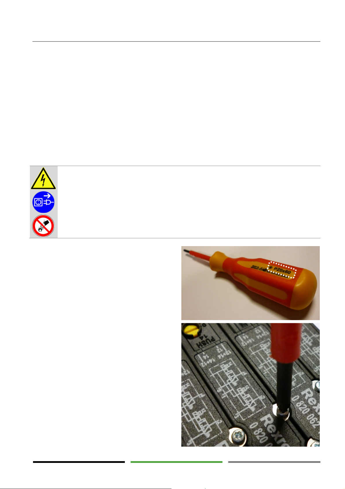
Maintenance and repair
DANGER !
– Electric voltage
10.1.6 Replacing filter elements
The filter elements in the filters prevent particles and aerosols in the compressed air flow from entering the
system. The filter elements in the filters will be clogged over time and thus the compressed air flow is throttled. To prevent operating errors from occurring, the filter elements have to be replaced regularly. Check the
differential pressure gauge at the filter (if available). When exceeding approximately 350 mbar, the elements
should be replaced. Replacement is due after one year at the latest.
1) Depressurise the filter.
For the instrument air filter see → page 5
For the upstream and downstream filters see → page 68
2) For filter replacement please proceed as described in the operating manual of the filter.
10.1.7 Replacing the pilot valves
The pilot valves (→ page 28) are crucial items for the
proper function of the dryer. They should be replaced
as a precautionary measure.
The pilot valve is mounted on the base of the valve
terminal by means of two bolts. (Type cross head
„Pozy-Drive“ DIN EN ISO 4757 – Z0)
Untighten the bolts to remove the pilot valve. Now
pull the pilot valve from the base.
Place the new pilot valve into position and gently pull
the bolts tight. The bolts are very fragile! Make sure
that you use the correct screw driver type PZ0!
Make sure that the bolt slides correctly into the old
thread of the base. First turn the bolt counter clockwise until the bolt drops into the first thread pitch
with a little click. Now turn clockwise. Turn both bolts
alternately and equally tight until the resistance noticeably rises. Make sure that the final position of the
pilot valve is straight.
The dryer is operated at electric voltages up to 690 V.
Touching live parts may result in serious injury or death.
Work on electrical components must only be carried out by qualified and authorised personnel.
Use a voltage detector to make sure the dryer has been disconnected from the power supply and
that there are no live parts before starting maintenance work.
In the event of fire, do not extinguish the fire using water.
73
Page 74
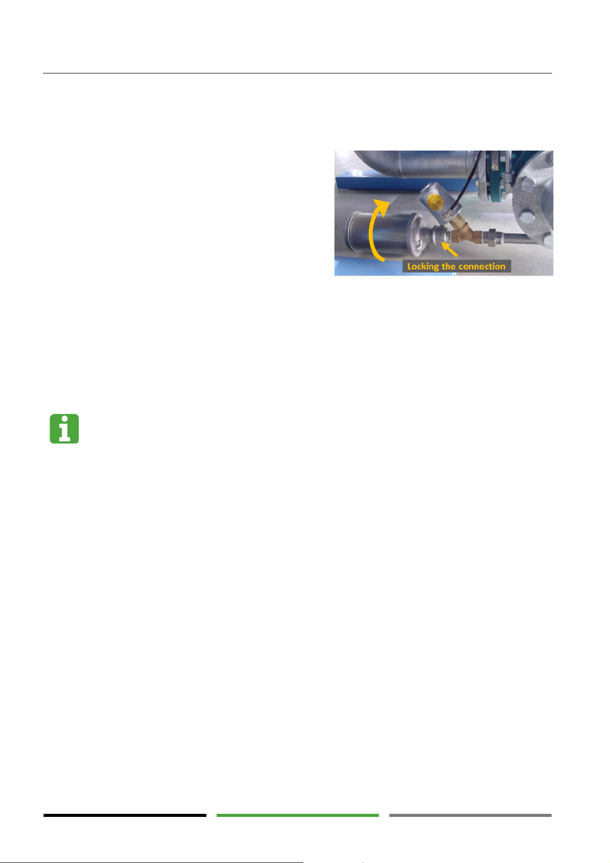
Maintenance and repair
Maintenance by manufacturer required
10.1.8 Replacing the expansion silencer
The expansion silencer (X1) is contaminated by dust and condensate over time and thus the expansion air flow
is throttled. To prevent operating errors from occurring, the expansion silencer has to be replaced regularly.
1) Decommission the dryer. (→ Page 67)
2) Depressurise the dryer. (→ Page 68)
3) Lock the connecting part between valve V5 and
expansion silencer (X1) using an appropriate tool
in order for valve (V5) not to turn.
4) Unscrew the old expansion silencer (X1) from the
connecting part using an appropriate tool.
5) Screw the new expansion silencer (X1) in the
connecting part and tighten it using an appropriate tool and some sealing tape.
6) Pressurise the dryer and commission the dryer again. (→ Page 67)
10.1.9 Checking the blower shaft bearing
Check the blower for unusual noise. A bearing damage is often preceded by strong noise development. We
recommend preventive maintenance every two years.
Replacing the bearings requires particular technical knowledge. Therefore, we recommend bearing replacement be carried out by the manufacturer.
10.1.10 Replace seals and seat kit of angle seat valves
Perform the replacement of the seals and seat kit of the angle seat valves (V4) and (V5) in the way it is described in the manual of the respective manufacturer.
74
Page 75
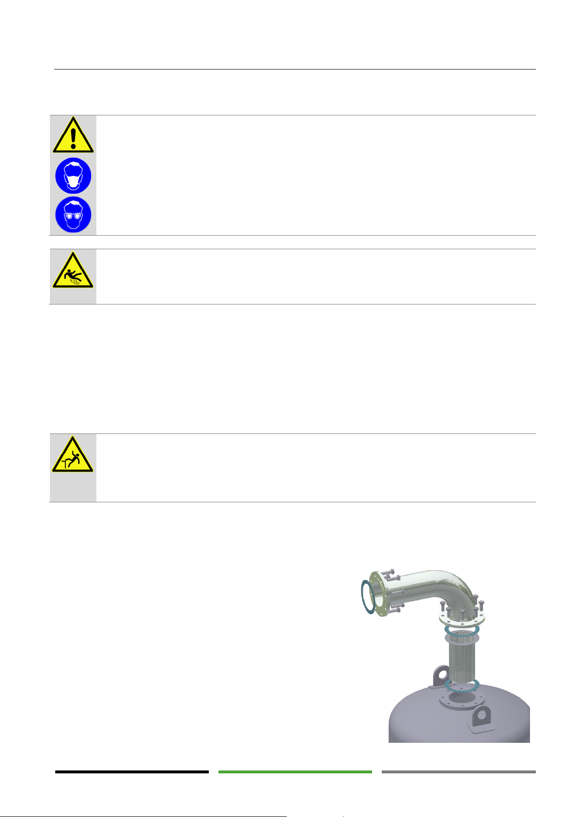
Maintenance and repair
CAUTION !
– Desiccant dust
WARNING !
– Risk of slipping
WARNING !
– Risk of falls
10.1.11 Checking and replacing the desiccant / cleaning the strainer basket
The desiccant is subject to ageing and its drying performance is reduced over time. The service life of the desiccant depends on numerous operating parameters and cannot be exactly predicted. The service life is approximately 3 to 5 years. Under very favourable conditions (e.g. oil-free compressed air) the service life may be
considerably longer. The quality of the desiccant can be assessed quite well when monitoring the operating
phases. If the adsorption phase is reduced significantly during operation in the "variable" cycle mode, the desiccant should be replaced. Desiccant replacement is generally useful as a preventive maintenance measure in
conjunction with other repair work. (See advisory note below)
Using the desiccant may lead to mineral dust formation.
Desiccant dust may cause eye and respiratory tract irritations.
Wear eye protection and a dust mask when handling the desiccant.
After desiccant replacement some amounts of desiccant may still remain on the floor.
The desiccant is very slippery and may result in serious fall injury.
Immediately remove residual desiccant properly from the floor.
The dryer must never be used as a climbing aid. The dryer components will not provide adequate
support and parts of the dryer may break off. Disregard may lead to dryer damages and falls with
serious injuries.
When working at height only use approved climb assist systems.
Desiccant replacement is part of a large inspection run. At the same time, other maintenance activities should
be carried out. (See maintenance table → page 70)
1) Decommission the dryer. (→ Page 67)
2) Depressurise the dryer. (→ Page 68)
3) Provide adequate support for the pipelines connected
to the dryer and make sure the connection points are
not subject to stress.
4) The pipe elbow is very heavy. Connect the pipe elbow to
the lifting equipment suitable for lifting the load.
5) Remove the pipe elbows above the vessels. (To main-
tain stability of the piping system it is possible to only
remove one pipe elbow and to carry out maintenance
on one vessel after the other.)
6) Remove the strainer basket (SB1, SB2) and clean it from
desiccant residues.
75
Page 76
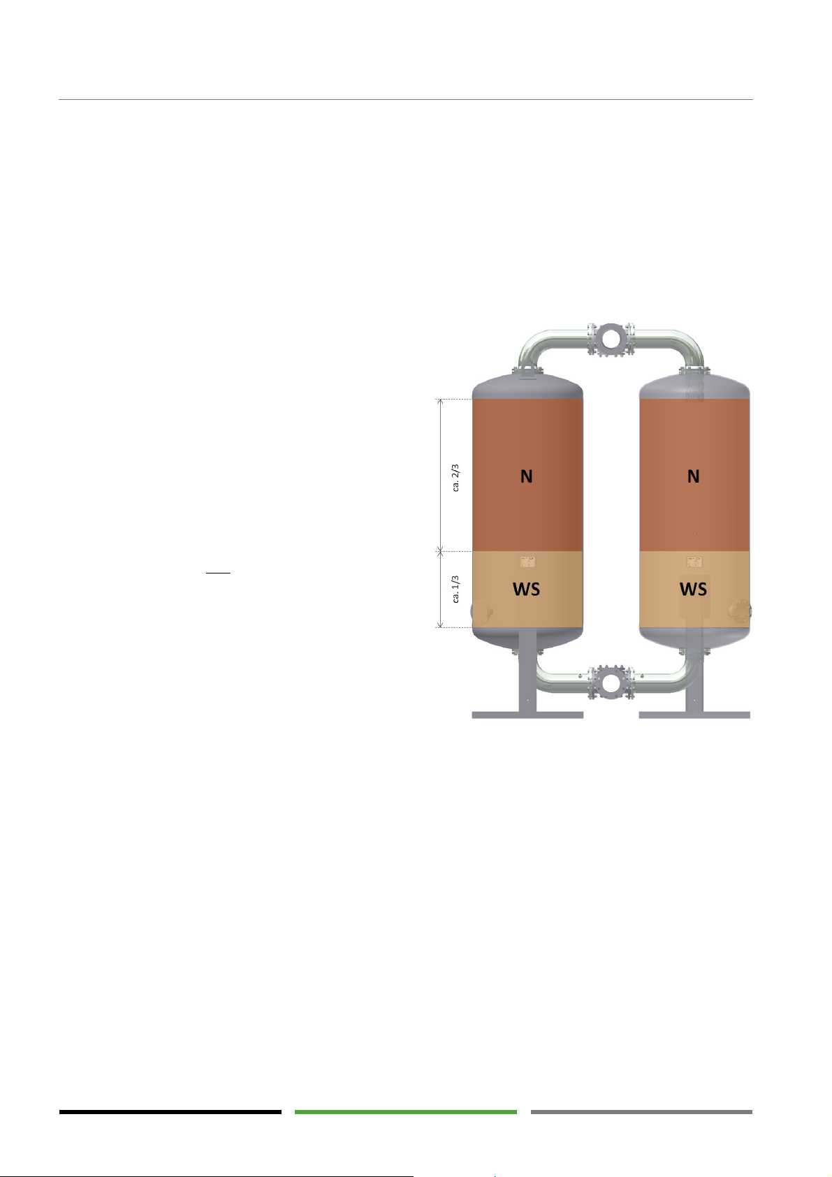
Maintenance and repair
7) Remove the seals and clean the flange surfaces from residues of the seals.
8) Provide an adequately sized container for the used desiccant. (Make sure to observe the volume in-
formation given on the vessel plate.)
9) Remove the used desiccant from the vessel using a suction device.
10) As an alternative, the desiccant can also be drained by opening the desiccant drain installed on the
side of the vessel. The residues in the container can be removed using a conventional industrial
vacuum cleaner.
11) Clean the nozzle of the desiccant drain and reclose the nozzle while using a suitable sealant.
12) Remove the used desiccant from the construction site.
13) Provide the new desiccant. Make sure to use
two different desiccant types which create
two separate layers in the vessel.
Distribute the different desiccant types
equally to the two vessels as shown in this
picture.
In the event you are unsure which desiccant
to fill in first, please contact the manufacturer.
14) Fill in the liquid waterproof desiccant (type
WS) first. It is the lower layer in the vessel.
15) Fill in the non-liquid-waterproof desiccant
(type N) last. It is the upper layer in the vessel. This type of desiccant will disintegrate
when getting in contact with liquid water.
16) Fill up the vessel almost to its full extent.
Make sure that the strainer basket (SB1, SB2)
can still be inserted in the vessel opening by
slightly pressing on it. During operation the
desiccant will be compressed to some extent
and the desiccant volume will be slightly reduced.
17) Reinsert the strainer basket (SB1, SB2) into the vessel using two new seals.
18) Reclose the vessel using the pipe elbow. First tighten the screws only lightly. Then tighten com-
pletely in a crosswise manner.
19) Clean the bottom thoroughly from desiccant residues.
20) Slowly pressurise the dryer again. (→ Page 63) Carry out a leak test using a leak detection spray. In
the event of leaks the dryer will have to be depressurised prior to repairing the leaks.
N = pure silica gel (amber, transparent)
WS = water proof silica gel (beige/brown-spotted)
Please note that, directly after desiccant replacement, the dew point may become worse. The new desiccant
will reach the full drying performance only after a longer operation period.
For the time directly after desiccant replacement it may be useful to select a dew point limit value as described
in the "Properly selecting the dew point limit value" advisory note. (→ Page 45)
76
Page 77

Maintenance and repair
Taking the inspection intervals for the vessels into account
Increased dust contents after desiccant replacement
Desiccant
Disposal
A routine inspection is required for the pressure vessels. In Germany, according to AD 2000 Code a
routine inspection has to be carried out every 5 years by a notified body.
Please note that different national regulations may apply in other countries.
We recommend replacing the desiccant in the course of this inspection run at the latest.
Combine desiccant replacement and vessel inspection. The manufacturer provides desiccant replacement in conjunction with "measures parallel to approval".
Filling the new desiccant in the dryer results in increased dust contents in the vessels. In the first
weeks after recommissioning the dust is forwarded to the downstream filter and the filter elements will deteriorate faster than during later operation. We therefore recommend to recommission the dryer using the old filter elements and to use the new filter elements and the new expansion silencer only after some weeks.
The desiccant used is not subject to labelling requirements according to the Hazardous Substances
Ordinance. Nevertheless, the common safety measures with regard to using chemicals apply.
The manufacturer will provide safety data sheets on request.
The desiccant may accumulate contaminants from the compressed air. Depending on the type of
contamination there may be a risk of injury or damage when using the desiccant. As the type of
contamination is not known to the manufacturer, the resulting risks cannot be evaluated in this
operating manual.
Dispose of the desiccant according to the local regulations.
Waste codes according to the Waste Catalogue Ordinance:
Non-contaminated desiccant: 06 08 99
Contaminated desiccant: The waste code will have to be determined by the waste producer
taking the type of contamination into consideration. The desiccant must be disposed of in an
appropriate disposal plant.
10.1.12 Replacing the rubber valve seat and the non-return valve
For replacing the rubber valve seat of regeneration valve (V3) and the non-return valve (RV1), please proceed
as described in the manuals of the relevant manufacturer.
77
Page 78

Appendix and technical documents
EC
– Declaration of
Conformity
Herewith we declare that the below mentioned products in their conception and design in which we placed
Manufacturer/authorised representative:
FST GmbH
Description of the assembly:
compressed air adsorption dryer
Description of the pressure equipment constituting
A list of the classified pressure equipment in this
Conformity assessment procedure followed:
Module B + D
Approving notified body:
Lloyd’s Register Quality Assurance GmbH
EC type
-
examination certificate
: DTM 0908138/A
-
807/1
Harmonised standards applied:
DIN EN ISO 12100;
Other technical standards and specifications applied:
AD 2000 Merkblätter
Other Community Directives applied:
2006/42/EG; 2004/108/EG; 2006/95/EG
In case
changes are made to the product without prior consultation and written approval by the manufactu
r-
Signature:
11. Appendix and technical documents
11.1 Declaration of Conformity
acc. to the pressure equipment directive 97/23/EG
them on the market have undergone the procedures of conformity assessment acc. to annex III of the above
mentioned directive and are in conformity with this directive.
Weiherdamm 17
57250 Netphen, Germany
type DTS 45 to DTS 8600
the assembly:
assembly has been communicated to the approving
notified body and was filed in the manufacturer’s
technical documentation.
(ID No.: 0525)
Am Sandtorkai 41
20457 Hamburg
DIN EN ISO 60204-1; DIN EN 60439-1
er this declaration will become void.
_________________________
16.10.2012, Norbert Hannen, General manager
78
Page 79

11.2 General arrangement drawing
Separate document
11.3 Process flow diagram
11.4 Pneumatic diagram
Appendix and technical documents
11.5 Wiring diagram
Separate document
79
Page 80
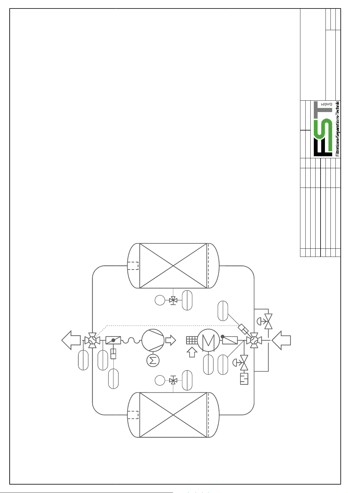
GO
Gas
-
Austritt
gas outlet
03
V3
GO
Gas
-
Austritt
gas outlet
03
RV1
1
adsorber vessel
butterfly or seat valve
non-return valve
blower with motor
heater
hose
sieve
sieve tray
silencer
limit switch
temperature transmitter
limiter thermostat
pressure gauge
Trocknerbehälter
Absperrklappe / -ventil
Rückschlagarmatur
Gebläse mit Motor
Erhitzer
Schlauch
Sieb
Siebboden
Schalldämpfer
Endlagenmelder
Temperaturtransmitter
Begrenzerthermostat
Manometer
gas inlet
regeneration gas inlet
pressure transmitter
pressure dew point transmitter
Drucktransmitter
Drucktaupunkttransmitter
regeneration gas outlet
R&I-Fließbild bis DTS 1100 V
Gas-Eintritt
Regenerationsgas-Eintritt
Regenerationsgas-Austritt
ZPI-S-100007
P&I-Diagram up to DTS 1100 V
AVRVMHPSSTXGSTT
GO
OPTION
TSHPIPT
V2
01
MT
MT
GJ
RJ
RO
S2
A2
HV2
PI
02
PT
02
01
GS
OPTION
erstellt/design C.Ruff, 04.01.10
geprüft/checked M.Schulte, 04.01.10
B Siebe / sieves 11.05.10 CR
A V4 verschoben / V4 moved 27.04.10 CR A2
Rev. Änderung/change Datum/date Name ersetzt/replacing: DT-PI-00007
V4
S3
H1
P1
TT
02
M1
RO
RJ
01
TT
TSH
01
V1
V5
GJ
GS
S1
PI
01
A1
PT
01
HV1
X1
ST1 ST2
Page 81
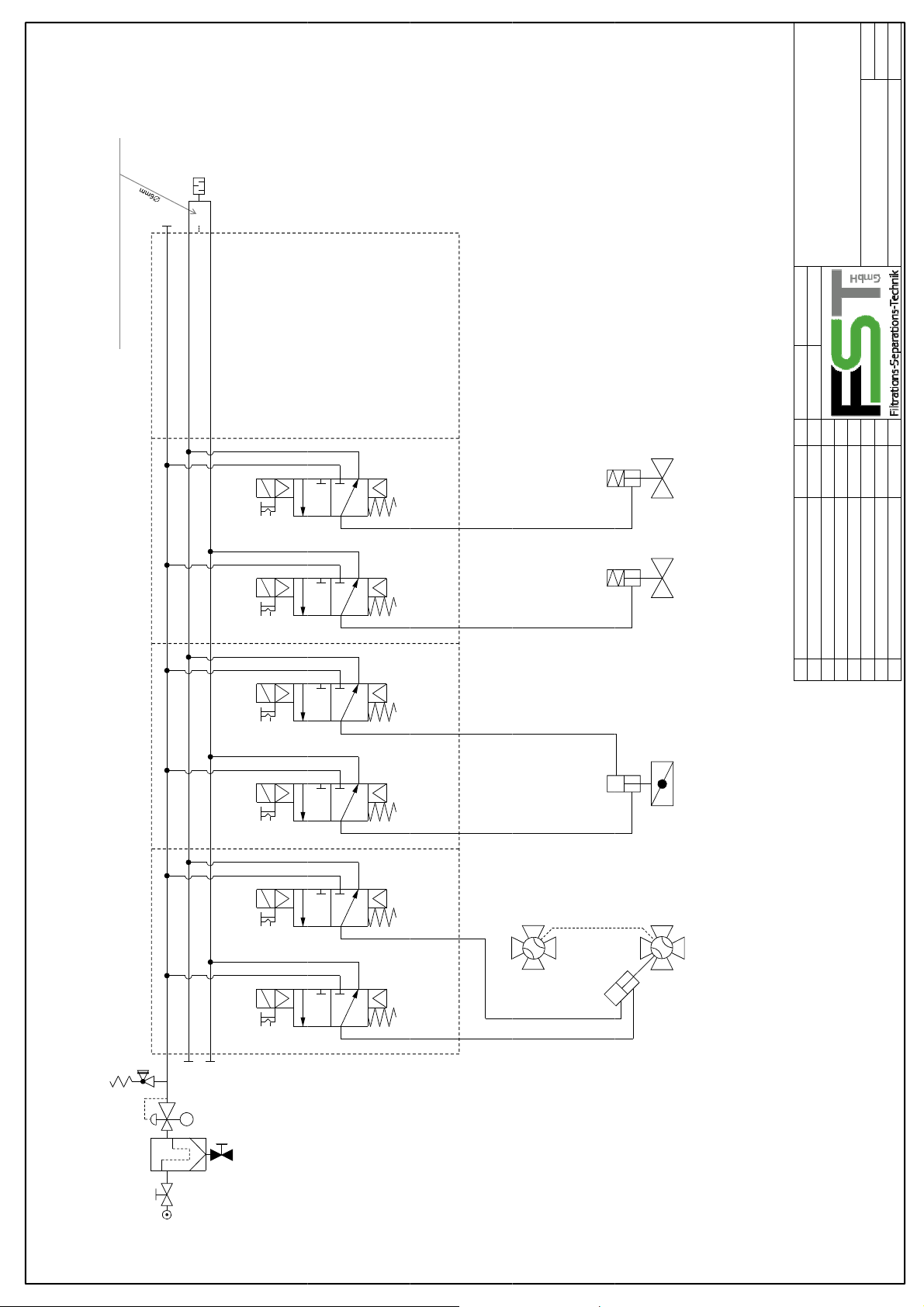
DieserAnschlussbleibtoffen!
connection
is
left
open!
‐
DTS
45
‐
V
R=Abluftöffnung derinternenPilotluft.
1
1
R
5
8mm
3
10mm
R=Exhaustopeningofinternalpilotair.
erstellt/design C.Ruff,22.02.2010
geprüft/checked T.Tappe 22.02.2010
V5
1
3
12
2
N.C.
auf
open
A
ZPP‐S‐100023
Pneumatic diagram DTS45‐1100V
8 bar
Art.Nr.:R480702211
8mm
1
10mm
3
V4
1
Y4 Y5
5
Y3.1 Y3.2
14
12
14
12
4
1
3
2
zu
closed
V2
B
V1
1
5
4
1
3
2
1
5
Y1 Y2
14
5
4
6mm
4 2 4 2 4 242
N.C.
auf
open
A
B3‐2‐Wege ‐Doppelventile/3‐2‐waydouble 14.1.2011 CR
A Detailsüberarbeitet/details revised 20.09.2010 CR A2
Rev. Änderung/change Datum/date Name ersetzt/replacing:DT‐PP‐000023
V3
auf
open
A
Küken‐Stellunggleichläufig
A
Plugvalves have samesenseof flow
WennY1angesteuertist,
dannistderTrock neraust rittauf
Behälter1(links)verbunden.
WhenY1isenergisedvessel1(left)
isconnectedtothedryeroutlet
PI
 Loading...