

Page 1

OPERATING INSTRUCTION
O11300G00169
07.2010
Compressed Air-Dryer
DFX 2 A – DFX 85 A
Page 2
Type Code
07.2010 EN_2
Series
DFX
Type Code
Model Type no.
DFX 2 B10-230-xxx-01 1130 A
DFX 4 B15-230-xxx-01 1131 A
DFX 5 B15-230-xxx-01 1132 A
DFX 7 B15-230-xxx-01 1133 A
DFX 9 B15-230-xxx-01 1134 A
DFX 11 B15-230-xxx-01 1135 A
DFX 13 B25-230-xxx-01 1136 A
DFX 15 B25-230-xxx-01 1137 A
DFX 18 B32-230-xxx-01 1138 A
DFX 23 B32-230-xxx-01 1139 A
DFX 30 B32-230-xxx-01 1140 A
DFX 36 B40-230-xxx-01 1141 A
DFX 45 B40-230-xxx-01 1142 A
DFX 55 B50-230-xxx-01 1143 A
DFX 65 B50-230-xxx-01 1144 A
DFX 75 B50-230-xxx-01 1145 A
Version air-cooled
DFX 85 B50-230-xxx-01 1146 A
Original instructions are in ENGLISH!
Technical modifications are subject to change without notice; errors not excluded.
FST GmbH
Im Teelbruch 106
D-45219 Essen
Phone +49 (0) 2054 8735 0
Fax +49 (0) 2054 8735 100
e-mail: [email protected]
Page 3
Table of contents
EN_3 07.2010
Page
Type code EN_2
Part 1 Important user information 1.1 General Notes EN_4
1.2 Legal requirements for the user EN_5
1.3 Safety regulations EN_6
1.4 Refrigerant handling EN_7
All safety notes in this operating instruction which may cause harm to personnel or
equipment, when ignored, are marked by the following symbols:
General danger symbol
Electrical danger symbol
1.5 First Aid EN_8
1.6 Disposal EN_8
Part 2 Installation 2.1 Transportation EN_9
2.2 Requirements on the place of installation EN_9
2.3 Installation (Mounting) EN_9
2.4 Compressed air connection EN_10
2.5 Electric Connection EN_10
2.6 Connection condensate drain EN_11
Part 3 Description 3.1 Designation EN_12
3.2 Intended use EN_12
3.3 Unit layout EN_12
3.4 Electronic regulator EN_12
3.5 Nominal power of CA-Dryer EN_13
3.6 Principle of operation EN_13
3.7 Mode of operation EN_13
3.8 Condensate draining EN_14
Part 4 Operation 4.1 Commissioning EN_15
4.2 Starting EN_15
4.3 Operation EN_15
4.4 Stopping EN_16
Part 5 Maintenance 5.1 Maintenance EN_17
5.2 Troubleshooting EN_18
5.3 Spare parts list EN_24
Part 6 Technical data 6.1 Technical data EN_25
Part 7 Appendix legend 7.1 Appendix legend EN_26
Appendix Apx 1 Units layout
Apx 2 Spare parts view
Apx 3 Wiring diagrams
Apx 4 PI diagram
Apx 5 Declaration EC-conformity
Page 4

Part 1 Important User Information
07.2010 EN_4
1.1 General notes
•
This compressed air-dryer is called CA-dryer in the
following.
•
The Company does not accept responsibility if safety
regulations are not met during handling, operation,
maintenance and repair, even though these are not strictly
stated in these operating instructions.
•
We recommend the notice of these operating instructions
verified by the operating personnel in writing (personnel file).
•
We recommend translation of these operating instruction
into native language of foreign workers.
•
The usability and the life cycle of the compressed air-dryer
as well as the avoidance of premature repairs depends on
proper operation, maintenance, care and competent repair
under consideration of these operating instructions.
•
Hints to figures and locations are in brackets, e.g. (Fig.3/7).
•
Due to our position as suppliers of components we do not
always know the final usage and total range of products’
application. We constantly improve our products to the latest
state of science and technology and therefore, we assume
that our product are free from defects in sense of product
liability. However, it cannot be excluded that during faulty
operation in critical areas of application especially at danger
to life and limb of persons involved, additionally safety
measures may be necessary. Therefore, we request the
user of our components / units, to ensure in his own interest,
to inform us about the application of our products in order to
initiate additional safety measures, if necessary.
•
Keep this manual for future reference.
Page 5

Important User Information
Part 1
EN_5 07.2010
1.2 Legal requirements for the user
1.2.1 Classification EC
regulation 97/23
• Due to classification into category 2 (type 1146A)
according to EC-Pressure Equipment directive, the CADryer are “systems to be monitored”.
1.2.2 Check of working
materials
• Before starting the CA-Dryer, the user has to check the
working materials and record this accordingly.
1.2.3 Periodical checks
• The user of the CA-Dryer has to find out the test periods
of the complete unit and the unit parts on base of a safety
related technical evaluation.
1.2.4 Instruction EN 378-1
• The user has to provide the instructions for the operators
as well as their information of the used working media. A
yearly instruction is mandatory.
1.2.5 Short Operating
Instruction EN 378-2
• A „Short Operating Instruction“ must be prepared by the
user and positioned next to the machine.
1.2.6 Documentation EN
378-4.3.1 EC regulation
842/2006
• The user is committed to create a unit record of the
refrigerating plant when using more than 3 Kg refrigerant.
A guideline can be provided by the service.
1.2.7 Maintenance EN 13 313
• Maintenance has to be provided by qualified personnel
only.
Page 6
Part 1 Important User Information
07.2010 EN_6
1.3 Safety Regulations
Attention!
The operator has to observe the national working-, operatingand safety regulations. Also existing internal factory regulations
must be met.
Maintenance and repair work must only be carried out by
specially trained personnel and, if necessary, under supervision
of a person qualified for this work.
• Protective or safety devices must not be removed, modified
or readjusted temporarily or permanently.
• User proper tools for maintenance and repair work only.
• Use original spare parts only.
Attention!
All maintenance and repair works must only be executed at
stopped machine, disconnected power supply and pulled mains
plug. Ensure that the CA-dryer cannot be switched on by
mistake.
• Prior to dismounting a part under pressure disconnect the
CA-dryer from all pressure sources and depressurize the CAdryer.
• Do not use inflammable solvents for cleanings.
• Keep the environment absolutely clean during maintenance
and repair works. Keep free of dirt by covering the parts and
free openings with clean cloth, paper or adhesive tape.
• Never weld at the pressure vessel or modify it in any way.
• Ensure that no tools, loose parts or similar are left in the
system.
• The casing of the CA-Dryer must not be stepped on.
• The CA-Dryer must not be used as deposit station.
• CA-Dryer must only be operated within the limits stated in the
nameplate.
• Condensate drain system access opening is intended to
manage the drain only (display visibility and test button) : a
deeper access inside the CA-Dryer may cause injuries due to
refrigerant hot piping.
Page 7

Important User Information
Part 1
EN_7 07.2010
1.4 Refrigerant
handling
•
Wear eye protection and protective gloves.
•
Avoid contact of liquid refrigerants with your skin (frostbite).
•
Do not inhale refrigerant vapours.
•
To avoid higher concentrations, all work rooms must be
ventilated very well. The opening of windows and doors may
not be sufficient, so an exhausting system must be used
directly at the supply point or near the floor.
•
Do not smoke, because fire might decompose the
refrigerant. The resulting substances are toxic and must not
be inhaled.
•
Do not have refrigerants escaped during filling or repair
work. Cover with tape.
•
Leave the room immediately and only enter after the room
has been sufficiently ventilated when refrigerant
concentrations (e.g. pipe line leakages) appear suddenly.
•
Execute welding and soldering works on refrigerating
systems in well ventilated rooms only. Refrigerants will be
decomposed in flames as well as in electrical arcs.
•
The resulting decomposition products are toxic.
•
Before welding and soldering at refrigerating systems, the
refrigerant must be removed.
•
A stinking smell points to decomposition of refrigerant due to
overheating:
- leave room immediately;
- ventilate room very well.
1.4.1 Refrigerant
charging and
discharging
•
refrigerant charging and discharging operations shall be
made by qualified personnel only.
•
Do not throw out refrigerant in the environment during
discharge operation. Use proper refrigerant recovery
system.
•
In case of refrigerant charging requirement, use only
refrigerant type and quantity as indicated in the CA-Dryer
nameplate.
1.4.2 Refrigerant characteristics
Refrigerant Chemical formula TLV GWP
R134a – HFC CH2FCF3 1000 ppm 1300
R407C – HFC
R32/125/134a (23/25/52)
CHF2CF3/CH2F2/CH2FCF3
1000 ppm 1653
Page 8
Part 1 Important User Information
07.2010 EN_8
1.5 First aid
1.5.1 General notes:
•
Immediately bring casualty into the fresh air or into a well
ventilated room.
•
Assistants must pay attention to self-protection!
•
Take off contaminated clothes.
•
Never leave the casualty unattended!
•
CALL THE DOCTOR and inform him that accident has
been caused by refrigerants, as to be read on the name
plate!
1.5.2
After inhaling:
•
Bring casualty into the fresh air, keep him warm, and let him
relax.
•
At breathlessness: Oxygene therapie
•
At apnoea: Resuscitation
•
Mouth-to-nose resuscitation, mouth-to-mouth resuscitation
or with equipment.
•
Medical treatment necessary
1.5.3
After skin contact:
•
At skin contact, clean with water and soap immediately.
•
After contact with the fluid, undercooled skin areas must be
cooled with warm (not hot) water.
1.5.4
After eye contact:
•
Flush well opened eye with running water for at least 10
minutes.
•
Contact doctor.
1.5.5
Notes for the
doctor:
•
Inform doctor about the used refrigerant.
•
After inhalation, deep breathing of a corticoid emulsive
dosing aerosol (e.g. Ventolair) as soon as possible.
•
Prohobition of using adrenergic drugs.
•
Prophylactic pulmonary edema after inhalation of
decomposition products / fire gases
1.6 Disposal
•
When disposing of used devices, pay attention to oil and
refrigerant in the hermetical sealed refrigerating circuit of
CA-dryers. Therefore, before dismounting, these operation
media must be disposed by a special company.
•
The used materials are listed on the recycling label inside
the CA-dryer.
Attention!
Do not dispose waste oil into the environment. Do not mix with
household rubbish and do not burn it unauthorized plants.
• The escape of refrigerant into the atmosphere must be
prevented by appropriate measures.
Page 9
Installation
Part 2
EN_9 07.2010
2.1 Transportation Transportation has to be carried out in the normal operating
position of the CA-dryer.
For a short time an inclined position of 45° is allowed.
Handle with care. Heavy blows could cause irreparable damage.
2.2 Requirements on
the place of
installation
At the site of installation, the CA-dryer can be installed without
anchorage or special foundation at the location desired.
The CA-dryer is provided for an ambient temperature of 25 °C.
Attention!
To avoid corrosion on components of the CA-dryer the
compressed and ambient air must be free of aggressive parts.
The CA-dryer are provided for inside mounting.
Deviating conditions require the consultation of the
manufacturer.
To prevent the condensate from freezing the room temperature
must not drop below +2 °C.
Attention!
At different ambient conditions pay attention to the layout data!
2.3 Installation
(mounting)
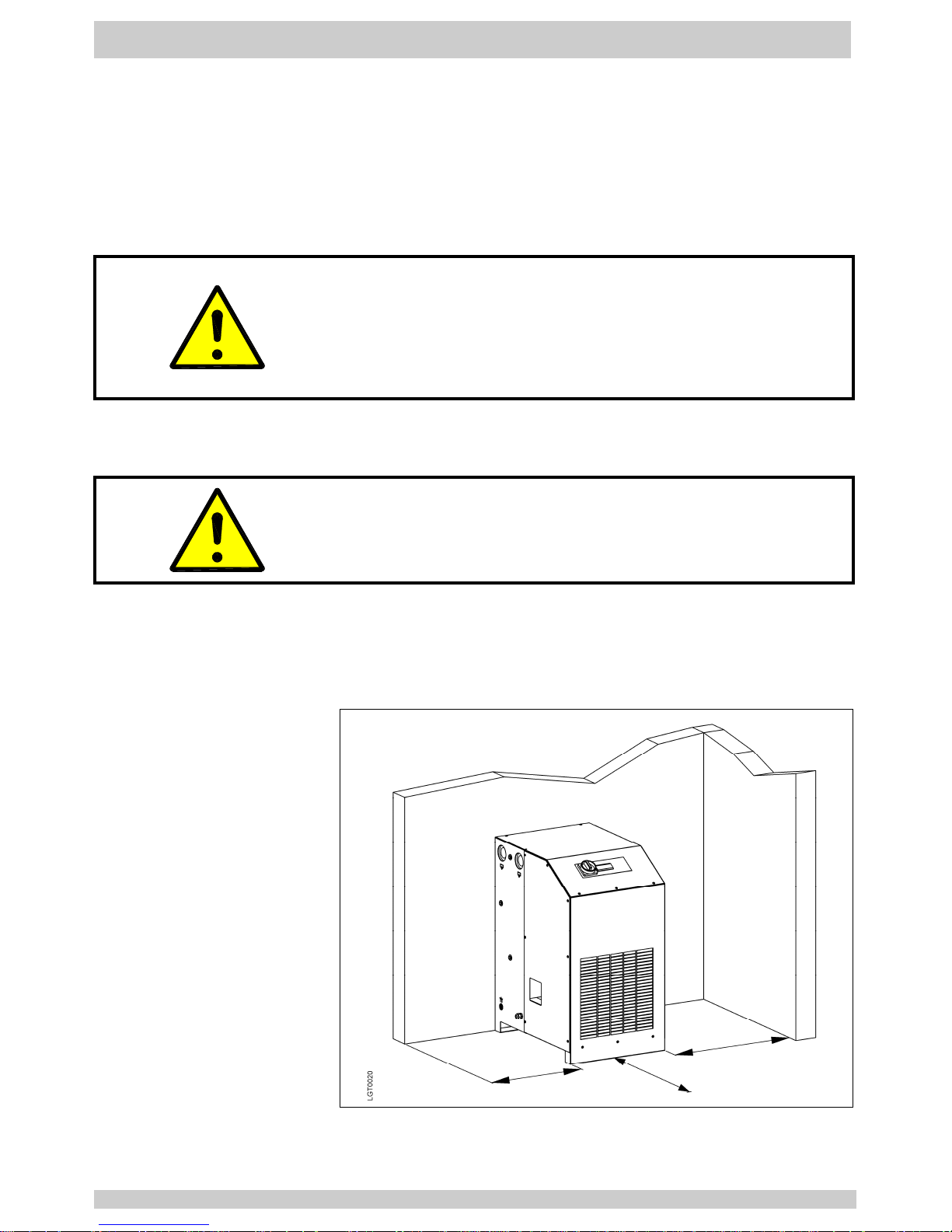
The CA-dryer must be installed that accessibility to the front
panel is ensured. Furthermore leave space for service purposes
on both sides of the CA-dryer (fig.2.3a).
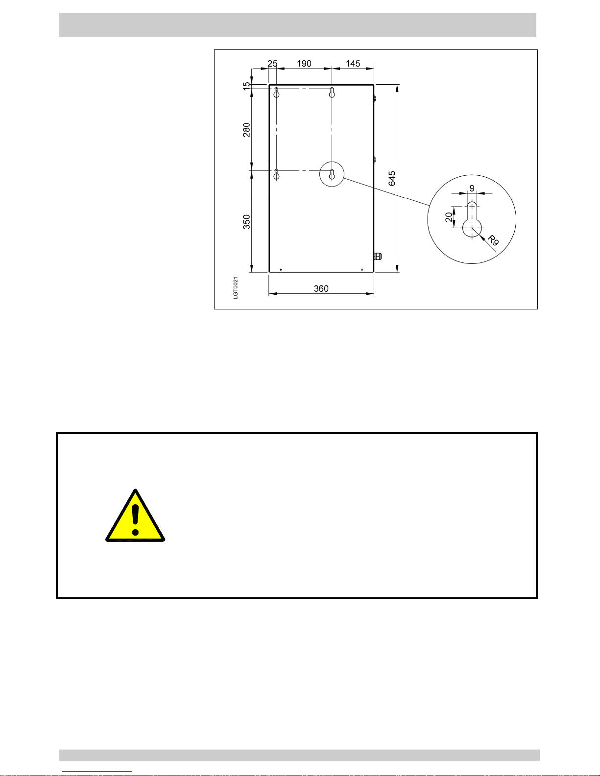
Wall mounting is possible with types 1130A-1137A (fig.2.3b).
Fig.
2.3a
Installation of CA-dryer
Page 10
Part 2 Installation
07.2010 EN_10
Fig.
2.3b
Preparation wall
mounting
2.3.1 Version air cooled The cooling air is sucked in by the refrigerant condenser (Apx
1/3) and discharged at the right side (Apx 1/4). Both areas must
be kept free and must non be obstructed.
2.4 Compressed air
connection
The connection must be executed acc. to marking at the CAdryer (Apx 1/1 + 1/2).
For service purposes the installation of a bypass line in
recommended (additional equipment).
Attention!
Before mounting the CA-dryer, welding residual, rust or other
pollution must be removed from the pipelines to be connected.
If pollution cannot be excluded, proper filter system must be
installed.
The compressed air pipes must be installed stress-free.
Expansion joints are recommended in case of vibrations and
pulsations.
CA-dryer must only be operated within the temperature and
pressure limits stated on the nameplate.
Prior to use, the user must fit safety / pressure relief devices on
the CA-system.
2.5 Electric connection The CA-dryers are completely equipped and wired. They
merely have to be connected to a power supply. The CA-dryer
are to be protected by slow-blow fuses as defined in the wiring
diagram.
Operating voltage: according to name plate data.
Page 11
Installation
Part 2
EN_11 07.2010
2.6 Connection
condensate drain
A hose already pre-mounted at the condensate drain leads the
condensate out of the CA-dryer (Apx 1/5). A connection by the
costumer has to be carried out corresponding to the local
conditions.
The CA-dryers separates water as well as oil from the
compressed air. The water/oil mixture must not be led into the
sewage. Water and oil must be separated by suitable
separators (additional equipment).
A minimum operating pressure of 2 bar is required for safe
operation.
Attention!
Route outflow so that persons or objects will not be struck by
condensate (condensate outlet at operating pressure)!
2.6.1 Connection
condensate
draining
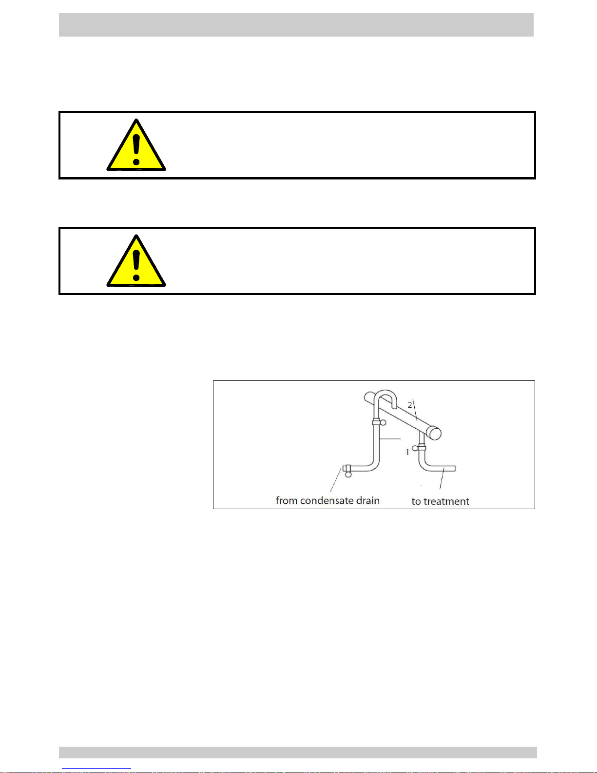
The condensate drain pipe (fig.2.6/1) may be fixed to the wall
with a rising slope of maximum 5m. thereby the minimum
operating pressure increases for 0,1 bar per meter. The
collecting pipe (fig.2.6/2) has to have at least the cross-section
of the condensate outlet.
Fig.
2.6
Connection
condensate draining
Page 12
Part 3 Description
07.2010 EN_12
3.1 Designation
Refrigerating compressed air-dryer (CA-dryer).
Version see type code (page 2).
3.2 Intended use Only compressed air will be dehumidified by the CA-dryer.
3.3 Unit Layout
See Appendix Apx 1 for CA-dryer components which are
accessible from outside.
Compressed air inlet
Compressed air outlet
Before maintenance works are to be executed at the CAdryer, the unit must be disconnected from the power
supply.
Risk of injury if the CA-dryer is not disconnected from the
power supply because of a freely rotating fan blade.
The refrigerant compressor of the refrigeration system
heats up during operation, so a risk of burn injuries is given
at maintenance works
3.3.1 Symbols
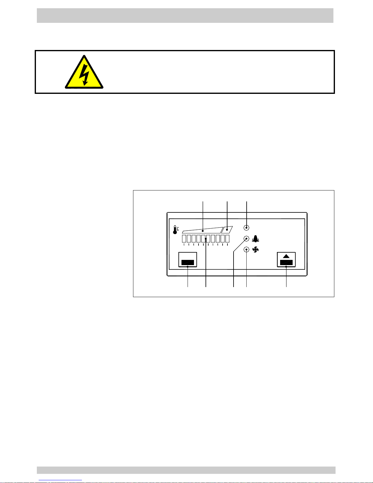
Condensate drain
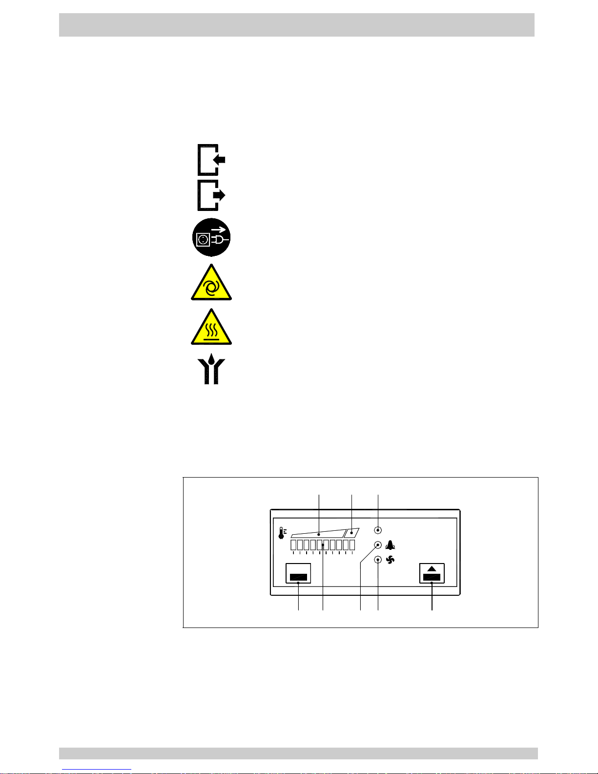
3.4 Electronic
regulator
The electronic regulator DDS5 is a controller specially designed for
CA-dryers. It operates on the basis of the micro processors and
performs three functions:
- Pressure dew point display
- Pressure dew point alarm
- Refrigerant condenser fan control (1130A-1138A)
P
Q
S
0
0
3
4
_
1
set
ON
7 1 8
5
6
4
3
2
1 10x Led green : Pressure dew point indication
2 Green area : Pressure dew point normal
3 Red area : Pressure dew point high
4 Led green : CA-dryer on
5 Led red : Alarm active (flashing)
6 Led yellow : refrigerant condenser fan on (1130A-1138A)
7 Set key
Fig.
3.4
Symbols
electronic
regulator
8 Up key
Page 13

Description
Part 3
EN_13 07.2010
3.5 Nominal power of
CA-dryer
The nominal power of the CA-dryer mentioned in the technical
data is related to a working pressure of 7 bar, a compressed air
inlet temperature of 35 °C as well as an ambient te mperature of
25 °C acc. to ISO 7183.
Lower working pressure, higher compressed air inlet
temperature and/or higher ambient temperatures overload the
compressor which causes to an increased pressure dewpoint
and the compressor can be stopped by internal safety devices.
At essentially deviating operating conditions, contact the
deliverer of the CA-dryer for support.
3.6 Principle of
operation
The CA-dryer includes a refrigerant system cooling the
compressed air flow. The steam saturation limit is lowered
causing condensate to fall out, which is removed by the
condensate drain.
The higher the cooling temperature difference of the
compressed air, the higher the amount of condensate.
The lower the cooling temperature of compressed air, the lower
the moisture content.
The lower limit of the compressed air cooling results from the
working principle of the CA-dryer, which is based on the
moisture separation in liquid form.
3.7 Mode of operation
3.7.1 Compressed air
side
The compressed air precooled in the Aftercooler and saturated
with moisture enters into the CA-dryer and is precooled in the
first cooling stage, the air-to-air heat exchanger without
additional energy. Cooling is carried out in counter flow to the
already cooled air heated during this process.
The cooling to the pressure dew point is performed in the
second cooling stage, the refrigerant-to-air heat exchanger
cooled by the refrigerant system installed. Subsequently, the
cooled compressed air is reheated in the air-to-air heat
exchanger as already described.
3.7.2 Refrigerant side The refrigerant is injected into the refrigerant-to-air heat
exchanger where it evaporates, thereby the compressed air is
cooled. The hot gas by-pass valve regulates the cooling
temperature and keeps the pressure dew point constant in
nearly all capacity stages. The refrigerant compressed by the
motor compressor is condensed within the condenser and is
available for the evaporation again.
3.7.3 Pressure dew point
control
Any compressed air dryer can be operated under partial load
due to lower compressed air flow or lower compressed air inlet
temperature in the range of 0 to 100% load in permanent
operation.
Page 14
Part 3 Description
07.2010 EN_14
3.8 Condensate
draining
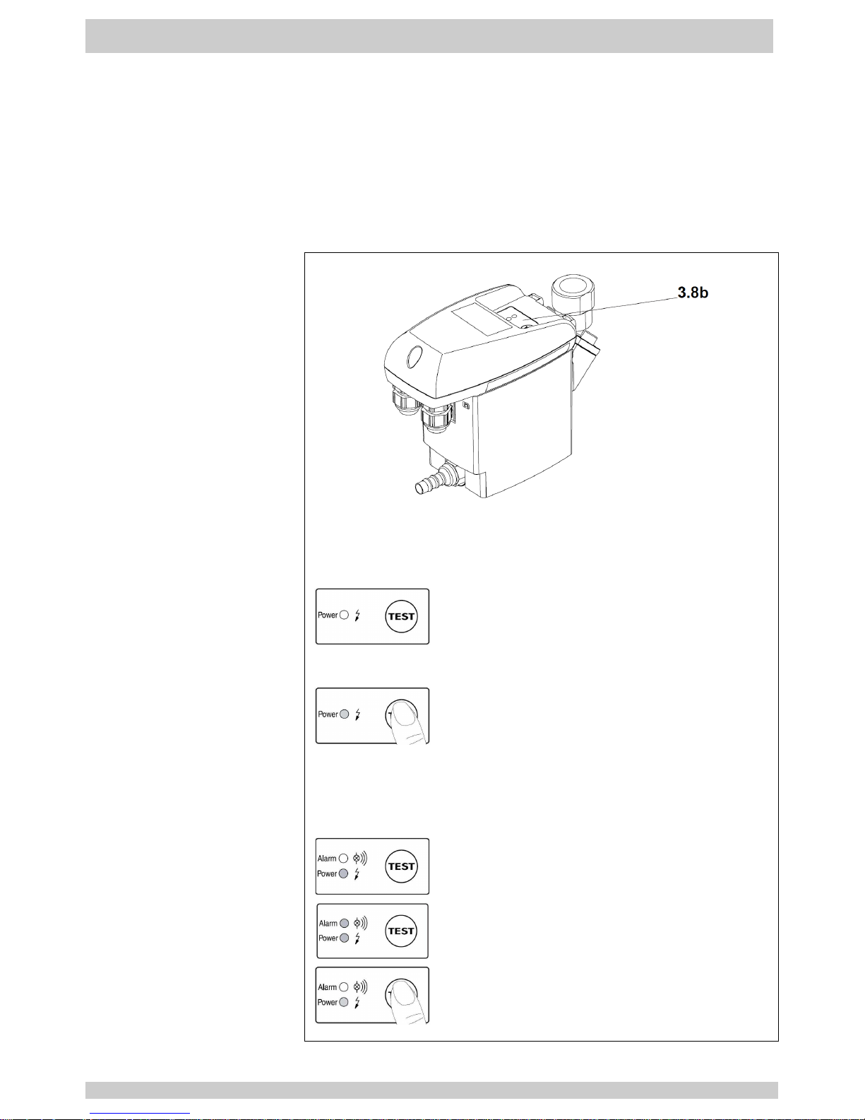
The condensate drain (fig.3.8a) automatically drains the
condensate. A minimum pressure of 2 bar is required for safe
operation.
3.8.1 Condensate drain
sensor-controlled
Once the container has filled with condensate, so that the
capacitive level sensor emits a signal, the internal solenoid valve
opens and the condensate is forced by the working pressure into
the discharge pipe.
The condensate drain electronic system ensures the closing of
the outlet opening before any compressed air can escape.
Fig.
3.8a
Condensate drain
General
Fig.
3.8b
Condensate drain
Operation panel
Type 1130A-1144A
The power LED is lit up green when operating voltage is being
applied.
- Ready for operation. Power On
If the condensate discharge is not functioning
properly, the valve will keep opening (about
every 2 seconds) so as to clear the fault
automatically, if possible.
- Test valve function (manual drainage).
Press button for approx. 2 seconds. In
response to longer pressing, the valve will
keep opening. Do not use this function for
continuous draining!
Type 1145A-1146A
The operating states are indicated by two LED’s.
- Ready for operation. Power on.
- Malfunction / Alarm.
- Test of valve function and manual drainage:
briefly press button.
- Press button for >1 minute to test the alarm
function.
Page 15
Operation
Part 4
EN_15 07.2010
4.1 Commissioning
After installation the CA-dryer is supplied with power via the
power cable or by operating the main switch (Apx 1/6).
Attention!
Before operating the operation switch (Apx 1/6), a waiting
period of at least 6 hours is absolutely necessary.
4.2 Starting
The CA-dryer is switched on via operation switch (Apx 1/6).
After approx. 5 minutes the compressed air admission is
possible by connecting the compressed air compressor.
The CA-dryer is designed for continuous operation and may
remain switched on during periods of no load, as it adapts to
the required performance automatically.
4.3 Operation Operation is indicated by the led “ON” of the electronic regulator
(fig.4.3/4)
The pressure dew point indication (fig.4.3/1) is showing the
pressure dew point reached by the CA-dryer.
P
Q
S
0
0
3
4
_
1
set
ON
7
1
8
5
6
432
4.3.1
Electronic regulator
- Changing factory
setting
Fig.4.3
1. Press SET key (7) for 2 seconds to change from display into
setup mode.
2. First data is ALARMON, shortly press SET key (7
) to go to
data FANON, shortly press SET key (7) to return to data
ALARMON.
3. In order to adjust actual data, keep pressed SET key (7) and
press UP key (8).
4. During the setup, led flashing will identify which data is
displayed :
- led ON (4) and ALARM (5) flashing = ALARMON data
- led ON (4) and FAN (6) flashing = FANON data
5. Setup exit is automatic after 2 minutes or by pressing UP key (8).
Page 16

Part 4 Operation
07.2010 EN_16
4.3.2
Electronic regulator
- Data range
ALARMON
RT1 temperature too high setpoint (ALARMON) is
adjustable in the range +2 … 20 °C (factory setting 18°C),
resolution 2°K, hysteresis -2°K.
(ie : ALARMON = 18°C; Alarm is active with RT1 temperature
≥18°C for at least 5 minutes; Alarm condition resets
immediately with RT1 temperature <16°C).
FANON
RT2 temperature fan setpoint (FANON) is adjustable in the
range +31 … 40 °C (factory setting 35°C), resolution 1 °K,
hysteresis -5°K.
(ie : FANON = 35°C; Fan start running with RT2 temperature
≥35°C; Fan stop running with RT2 temperature <30°C).
4.4 Stopping At standstill periods, the CA-dryer is switched off with the
operation switch (Apx 1/6).
For longer standstill periods or service works, the CA-dryer
is switched off by pulling the power plug (Apx 1/8).
Page 17
Maintenance
Part 5
EN_17 07.2010
5.1 Maintenance
Attention!
Prior to any maintenance works all safety regulations for
electrical systems and units must be observed (see also
part 1).
Maintenance intervals highly depend on the model of
operation and the ambient conditions on site, the intervals
below are only to be understood as general
recommendations.
5.1.1 Daily maintenance a) Check function of condensate drain.
Check, if water is drained.
Test valve function (manual drainage):
Press button for approx. 2 seconds.
In response to longer pressing, the valve will keep
opening.
Do not use this function for continuous draining!
b) Monitor pressure dew point (fig.3.4/1). In case of
differences to normal operation (see 5.2.2, 5.2.3).
c) Verify the refrigerant condenser for cleanliness.
5.1.2 Weekly
maintenance
Inspection and cleaning of condensate draining system if
necessary.
5.1.3 Yearly maintenance Condensate drain: replace service unit.
For further information see separate drain instruction.
Leak tightness check : CA-Dryers mentioned in this manual
have refrigerant charge ≤30 kg (refrigerant quantity as
stated in the nameplate) : the maximum allowed leak rate of
2 % must not be exceeded.
5.1.4 Periodic checks at
pressure vessels
CA-Dryer type 1146A is included into the pressure vessel
guideline category II, fluid group 2 and has a maximum
pressure of 14 bar.
Periodic checks must be done according to National
legislations and the determinations of the user.
Attention!
Maintenance work must be performed at the depressurized
condensate drain only. For this purpose, the installation of a
bypass line is recommended.
Page 18

Part 5 Maintenance
07.2010 EN_18
5.2 Trouble shooting
Symptom
Cause ⇒⇒⇒⇒ Remedy
5.2.1 No Function 1. Check and ensure power supply if necessary.
2. If the power supply is ok, contact service or send CA-dryer
to the manufacturer.
5.2.2 Pressure dew point
too high
1. Temporary overload of the CA-dryer due to non-uniform
compressed air consumption ⇒⇒⇒⇒ check CA-dryer’s capacity
(see 3.4).
2. Ambient temperature too high or the room aeration is
insufficient ⇒⇒⇒⇒ reduce temperature and/or provide proper
ventilation.
3. CA-dryer volume flow too high ⇒⇒⇒⇒ reduce volume flow; ⇒⇒⇒⇒
check whether CA-dryer’s capacity is properly selected,
increase CA-dryer’s capacity.
4. RT1 dew point sensor doesn’t detect the temperature
properly ⇒⇒⇒⇒ ensure the sensor is pushed into the bottom of
probe well or RT1 dew point sensor need to be replaced.
5. Refrigerant condenser fan is never running ⇒⇒⇒⇒ see 5.2.6.
6. Refrigerant condenser is polluted ⇒⇒⇒⇒ clean condenser.
7. Hot gas by-pass valve is out of setting ⇒⇒⇒⇒ contact service.
8. Leak in the refrigerating fluid circuit ⇒⇒⇒⇒ contact service.
5.2.3 Pressure dew point
too low
1. Ambient temperature is too low ⇒⇒⇒⇒ restore normal condition.
2. (type 1130A-1138A) Refrigerant condenser fan is always on
and electronic regulator’s FAN led is flashing ⇒⇒⇒⇒ see
5.2.11.2.
3. (type 1139A-1146A) Refrigerant condenser fan is always on
⇒
⇒⇒
⇒ Fan control pressure switch SPV is defective ⇒⇒⇒⇒ contact
service.
4. Switch off CA-dryer and maintain compressed air flow. After
approx. half an hour, the pressure dew point will return to
normal value. Restart the unit. If the pressure dew point
decrease again contact service.
5.2.4 Water in
compressed air
system
1. Condensate drain is not drained sufficiently ⇒⇒⇒⇒ see 5.2.12.
2. CA-operating pressure too low ⇒⇒⇒⇒ increase operating
pressure; ⇒⇒⇒⇒ check whether CA-dryer’s capacity is properly
selected, increase CA-dryer’s capacity.
3. Temporary overload of the CA-dryer due to non-uniform
compressed air consumption ⇒⇒⇒⇒ check CA-dryer’s capacity
(see 3.4).
4. CA-dryer volume flow too high ⇒⇒⇒⇒ reduce volume flow; ⇒⇒⇒⇒
check whether CA-dryer’s capacity is properly selected,
increase CA-dryer’s capacity.
5. CA-inlet temperature too high ⇒⇒⇒⇒ restore normal conditions.
6. (Only with installed bypass line) Bypass valve is open ⇒⇒⇒⇒
close bypass valve.
7. (Only with installed bypass line) Bypass valve is leaking
⇒
⇒⇒
⇒ seal or replace bypass valve.
Page 19

Maintenance
Part 5
EN_19 07.2010
5.2.5 Stopping CA-dryer
during operation
1. Compressor’s internal overload protection (klixon) is tripped
⇒
⇒⇒
⇒ eliminate cause of trouble (see 3.4) or contact service.
CA-dryer will restart automatically after compressor has
cooled down.
Note: the immediate restarting of the unit is not possible
because the compressor’s overload protection requires a
minimum time to cool down to an acceptable operating
temperature.
2. Compressor or starting device is defective ⇒⇒⇒⇒ contact
service.
3. CA-dryer volume flow too high ⇒⇒⇒⇒ reduce volume flow; ⇒⇒⇒⇒
check whether CA-dryer’s capacity is properly selected,
increase CA-dryer’s capacity.
4. CA-inlet temperature too high ⇒⇒⇒⇒ restore normal conditions.
5. Ambient temperature too high or the room aeration is
insufficient ⇒⇒⇒⇒ Reduce temperature or provide proper
ventilation.
6. Refrigerant condenser fan is never running ⇒⇒⇒⇒ see 5.2.6.
7. Refrigerant condenser is polluted ⇒⇒⇒⇒ clean condenser.
8. CA-operating pressure too low ⇒⇒⇒⇒ increase operating
pressure; ⇒⇒⇒⇒ check whether CA-dryer’s capacity is properly
selected, increase CA-dryer’s capacity.
9. (type 1142A-1146A) Safety thermo-switch FTS is tripped ⇒⇒⇒⇒
see 5.2.8.
10. (type 1143A-1146A) Safety high pressure-switch FPA is
tripped ⇒⇒⇒⇒ see 5.2.9.
5.2.6 Refrigerant
condenser fan is
never running
1. Check and ensure electric wiring.
2. Fan’s internal overload protection is tripped ⇒⇒⇒⇒ eliminate
cause of trouble (see 3.4) or contact service. Fan will restart
automatically after it has cooled down.
3. (type 1130A-1138A) Electronic regulator is defective ⇒⇒⇒⇒
contact service.
4. (type 1139A-1146A) Fan control pressure switch SPV is
defective ⇒⇒⇒⇒ contact service.
5. Leak in the refrigerating fluid circuit ⇒⇒⇒⇒ contact service.
5.2.7 High differential
pressure at CA-side
1. CA-dryer volume flow too high ⇒⇒⇒⇒ reduce volume flow; ⇒⇒⇒⇒
check whether CA-dryer’s capacity is properly selected,
increase CA-dryer’s capacity.
2. CA-operating pressure too low ⇒⇒⇒⇒ increase operating
pressure; ⇒⇒⇒⇒ check whether CA-dryer’s capacity is properly
selected, increase CA-dryer’s capacity.
3. Pressure dew point too low ⇒⇒⇒⇒ see 5.2.3.
4. Condensate drain is not drained sufficiently ⇒⇒⇒⇒ see 5.2.12.
5. Heat exchanger polluted ⇒⇒⇒⇒ contact service.
Page 20
Part 5 Maintenance
07.2010 EN_20
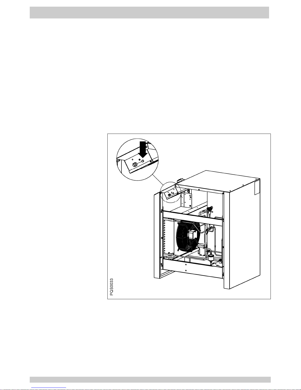
5.2.8
Safety thermo-switch
FTS is tripped
(type 1142A-1146A)
1. CA-dryer volume flow too high ⇒⇒⇒⇒ reduce volume flow; ⇒⇒⇒⇒
check whether CA-dryer’s capacity is properly selected,
increase CA-dryer’s capacity.
2. CA-inlet temperature too high ⇒⇒⇒⇒ restore normal conditions.
3. Ambient temperature too high or the room aeration is
insufficient ⇒⇒⇒⇒ reduce temperature and/or provide proper
ventilation.
4. Refrigerant condenser fan is never running ⇒⇒⇒⇒ see 5.2.6.
5. Refrigerant condenser is polluted ⇒⇒⇒⇒ clean condenser.
6. CA-operating pressure too low ⇒⇒⇒⇒ increase operating
pressure; ⇒⇒⇒⇒ check whether CA-dryer’s capacity is properly
selected, increase CA-dryer’s capacity.
7. Leak in the refrigerating fluid circuit ⇒⇒⇒⇒ contact service.
8. Safety thermo-switch FTS is defective ⇒⇒⇒⇒ contact service.
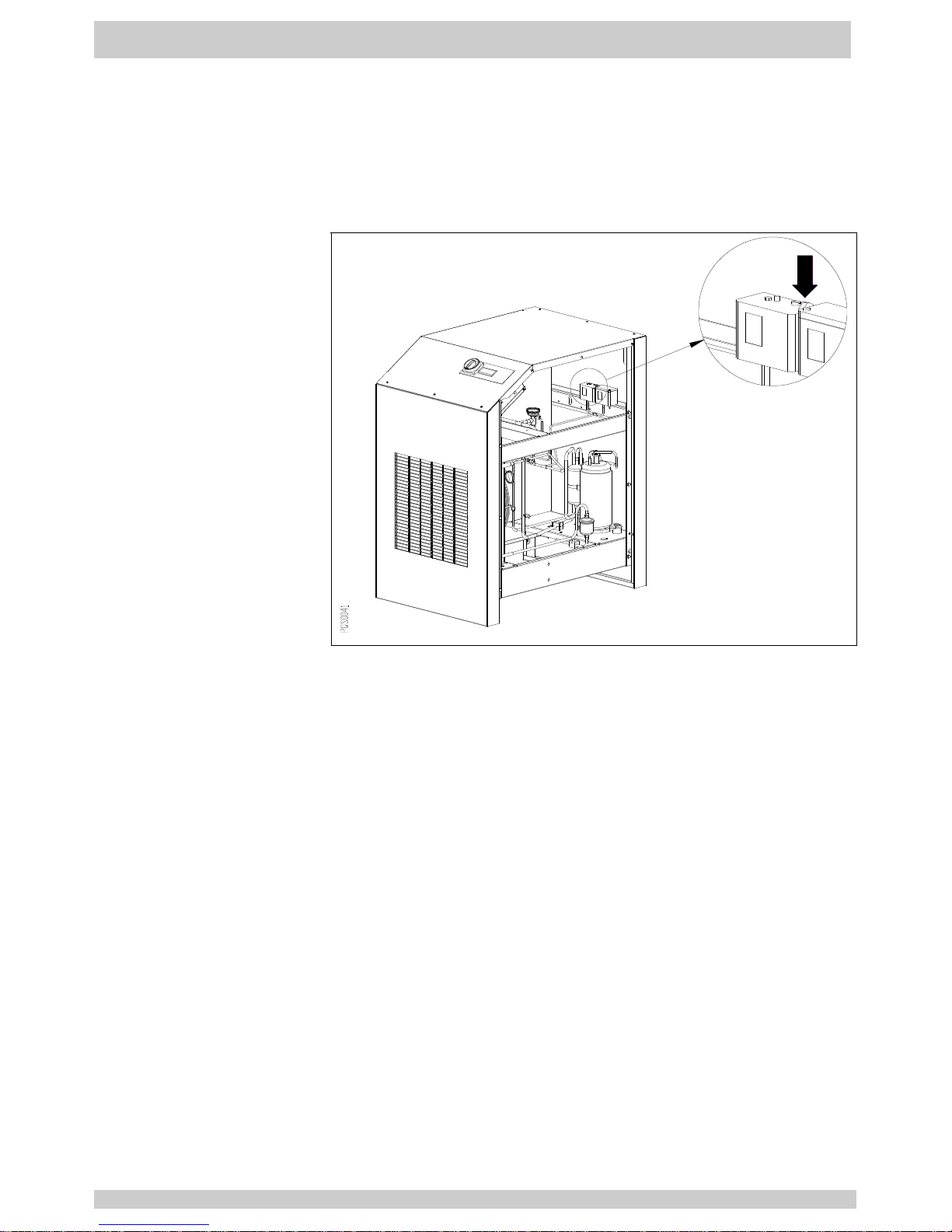
Note: Safety thermo-switch FTS require a reset : press
reset button (fig.5.2.8).
Fig.
5.2.8
Safety thermo-switch
FTS reset button
Page 21
Maintenance
Part 5
EN_21 07.2010
5.2.9 Safety high
pressure-switch
FPA is tripped
(type 1143A1146A)
1. Ambient temperature too high or the room aeration is
insufficient ⇒⇒⇒⇒ reduce temperature and/or provide proper
ventilation.
2. Refrigerant condenser fan is never running ⇒⇒⇒⇒ see 5.2.6.
3. Refrigerant condenser is polluted ⇒⇒⇒⇒ clean condenser.
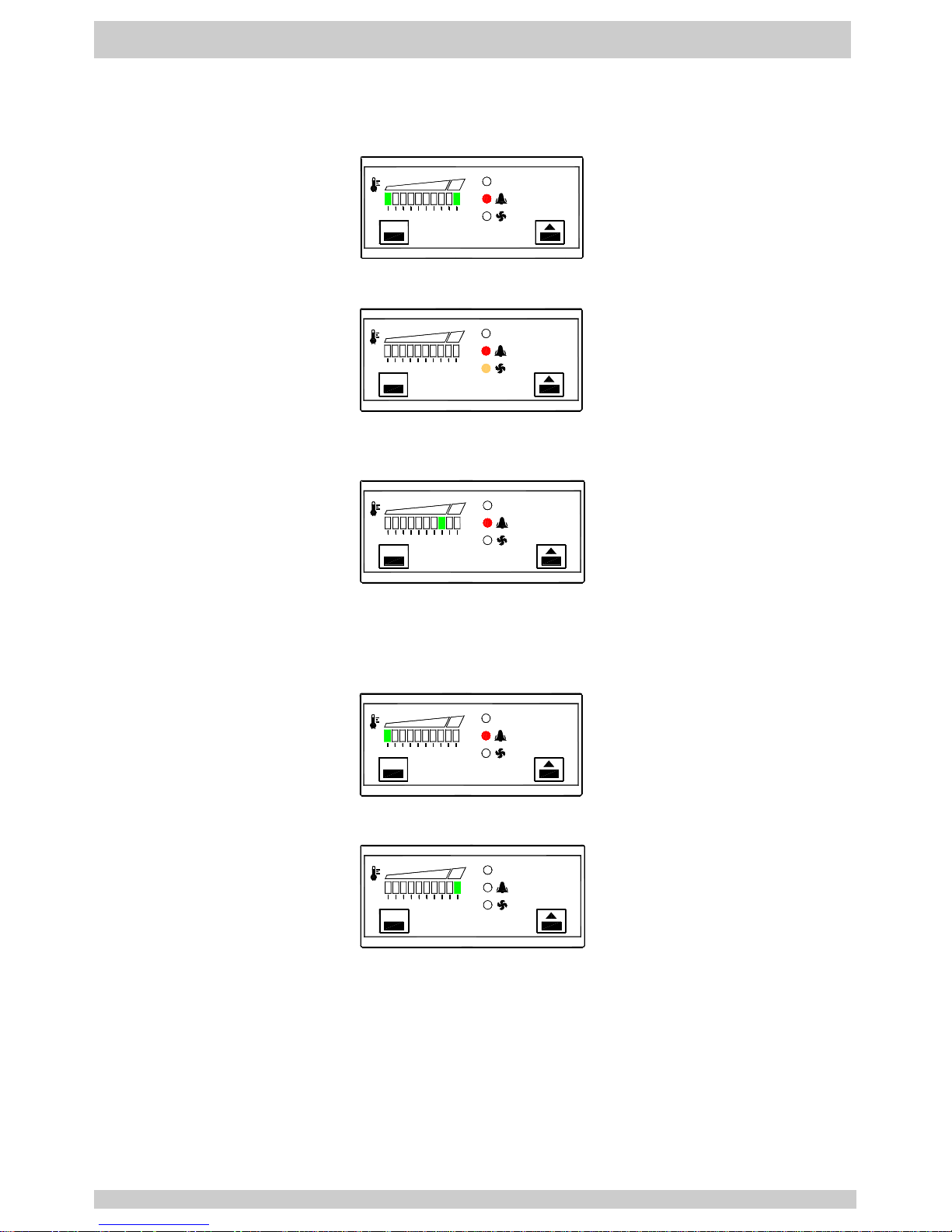
Note: Safety high pressure-switch FPA require a reset :
press reset button (fig.5.2.9).
Fig.
5.2.9
Safety high
pressure-switch FPA
reset button
Page 22
Part 5 Maintenance
07.2010 EN_22
5.2.11
Electronic regulator DDS5
Symptom
Cause ⇒⇒⇒⇒ Remedy
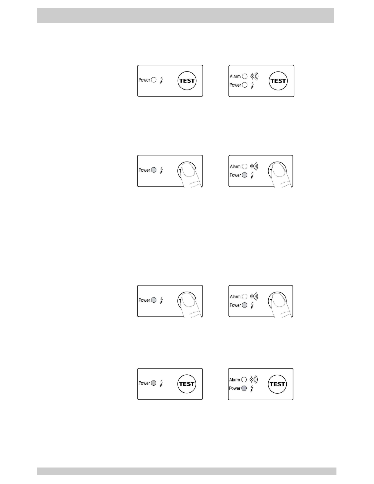
5.2.11.1
Alarm led and
display 1st (left)
and 10th (right) led
are flashing
P
Q
S
0
0
3
4
_
2
set
ON
RT1 dew point sensor is defective ⇒⇒⇒⇒ replace it.
5.2.11.2
Alarm led and Fan
led are flashing
(type 1130A-1138A)
P
Q
S
0
0
3
4
_
3
set
ON
RT2 fan control sensor is defective ⇒⇒⇒⇒ replace it.
Note: refrigerant condenser fan is always running.
5.2.11.3
Alarm led is
flashing and
display led is
lighted
P
Q
S
0
0
3
4
_
4
set
ON
Pressure dew point alarm (higher than ALARMON setpoint ⇒⇒⇒⇒
see 5.2.2 and 4.3.
Note: alarm become active 5 minutes later with dewpoint
temperature continuously higher than ALARMON setpoint
5.2.11.4
Alarm led and
display 1st (left)
led are flashing
set
P
Q
S
0
0
3
4
_
5
ON
Pressure dew point too low (lower than -1°C) ⇒⇒⇒⇒ see 5.2.3.
5.2.11.5
Display 10th (right)
led is flashing
set
P
Q
S
0
0
3
4
_
6
ON
Pressure dew point too high (higher than 24°C) ⇒⇒⇒⇒ see 5.2.2.
Note: Alarm led could be lighted or not (alarm become active
5 minutes later with dewpoint temperature continuously
higher than ALARMON setpoint)
Page 23
Maintenance
Part 5
EN_23 07.2010
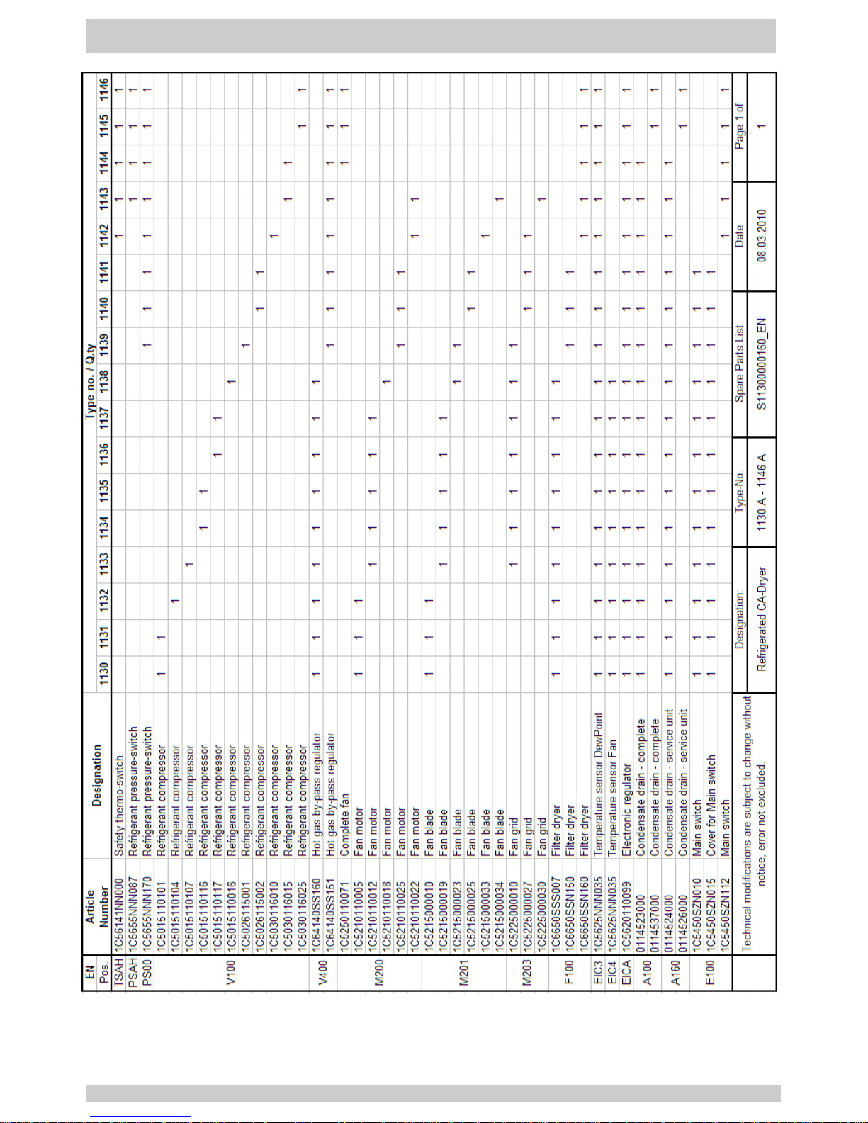
5.2.12 Condensate drain
Symptom
Cause ⇒⇒⇒⇒ Remedy
5.2.12.1
LED not lighting
up
Power supply faulty.
Power supply board defective.
- Check voltage on type plate.
- Check connections.
- Check of the circuit boards for possible damage to be carried
out by qualified personnel only.
5.2.12.2
Pressing of test
button, but no
condensate
discharge
Feed and / or outlet line shut off or blocked.
Worn parts (seals, valve core, diaphragm).
Power supply board defective.
Service unit defective.
Dropping below necessary minimum pressure.
Maximum pressure exceeded.
- Check feed line and outlet line
- Check if valve opens audibly (press test button several times).
- Check of the circuit board for possible damage to be carried
out by qualified personnel only.
- Check operating pressure.
5.2.12.3
Condensate
discharge only
when test button
is being pressed
Feed line with insufficient slope; cross-section too small.
Excessive condensate quantities.
Service unit extremely dirty.
- Lay feed line with adequate slope
- Replace service unit.
5.2.12.4
Device keeps
blowing off air
Service unit defective or dirty.
- Replace service unit.
Page 24
Part 5 Maintenance
07.2010 EN_24
Page 25
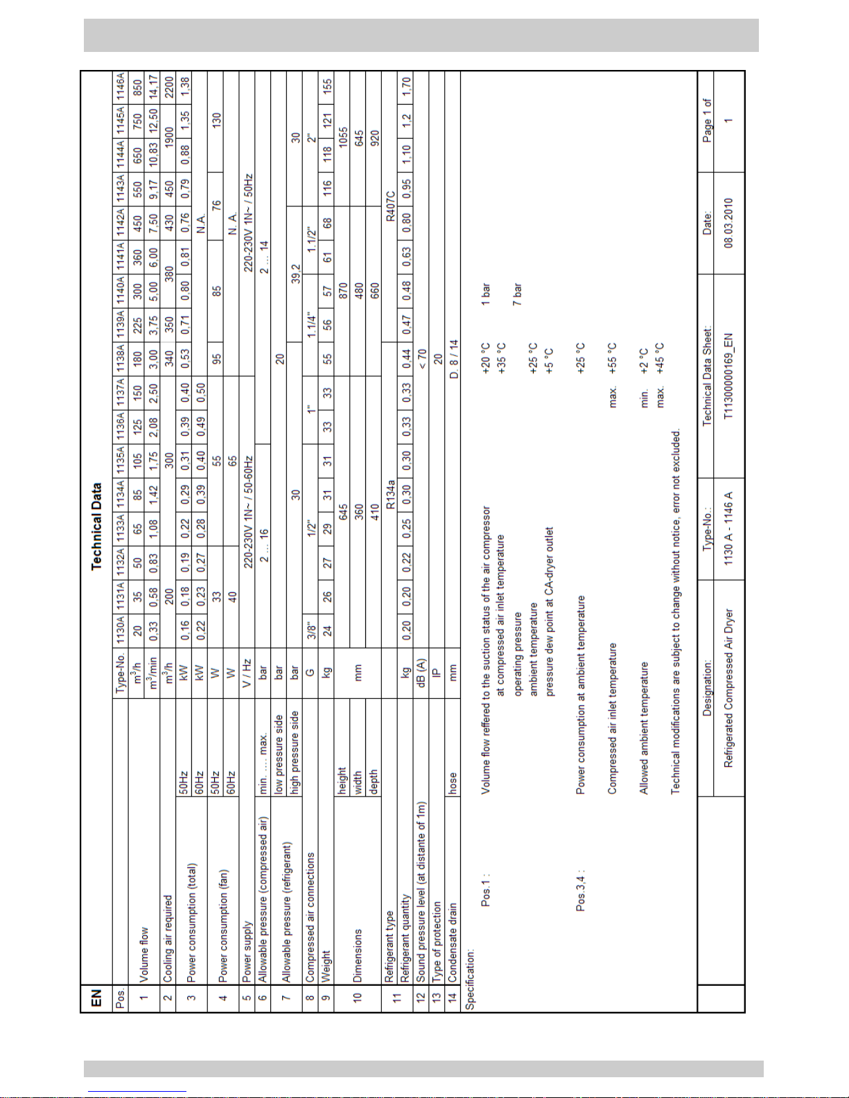
Technical Data
Part 6
EN_25 07.2010
Page 26

Part 7 Legend Appendix
07.2010 EN_26
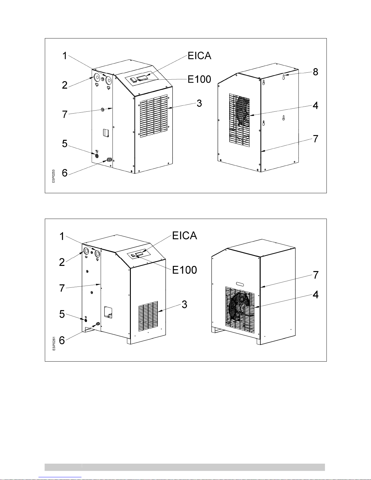
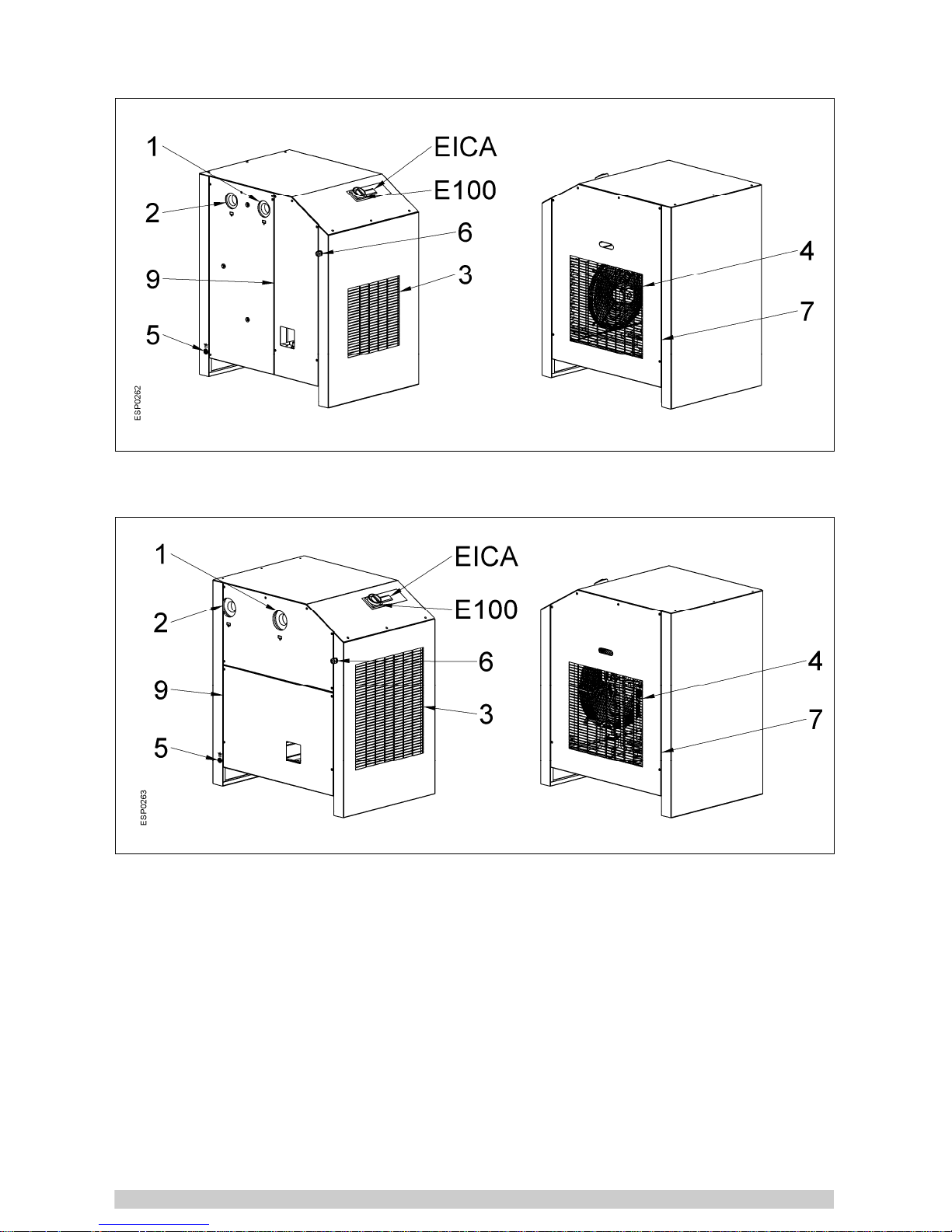
APX 1
1
2
3
4
5
Compressed air inlet
Compressed air outlet
Cooling air inlet
Cooling air outlet
Condensate drain
6
7
8
E100
EICA
Electric connection
Service access
Fixing holes
Operation switch
Electronic regulator
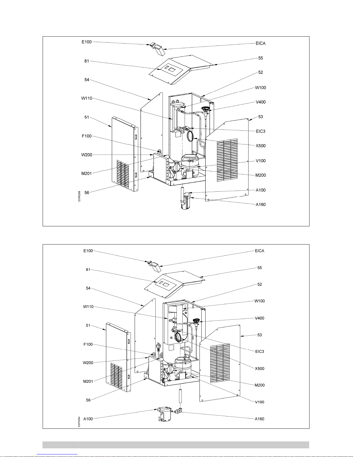
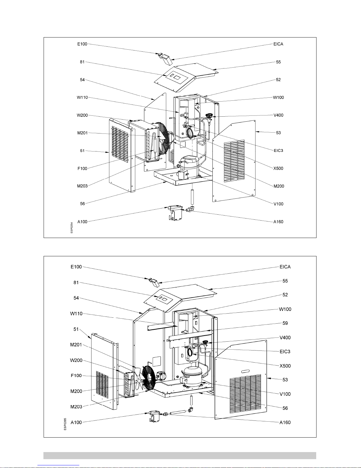
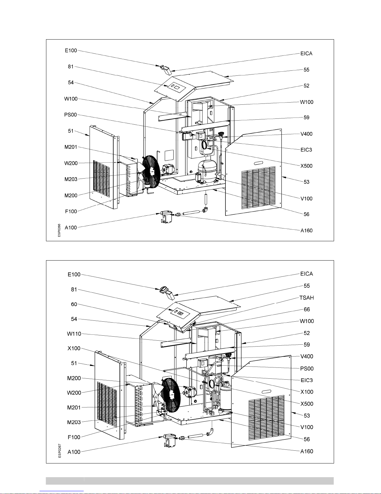
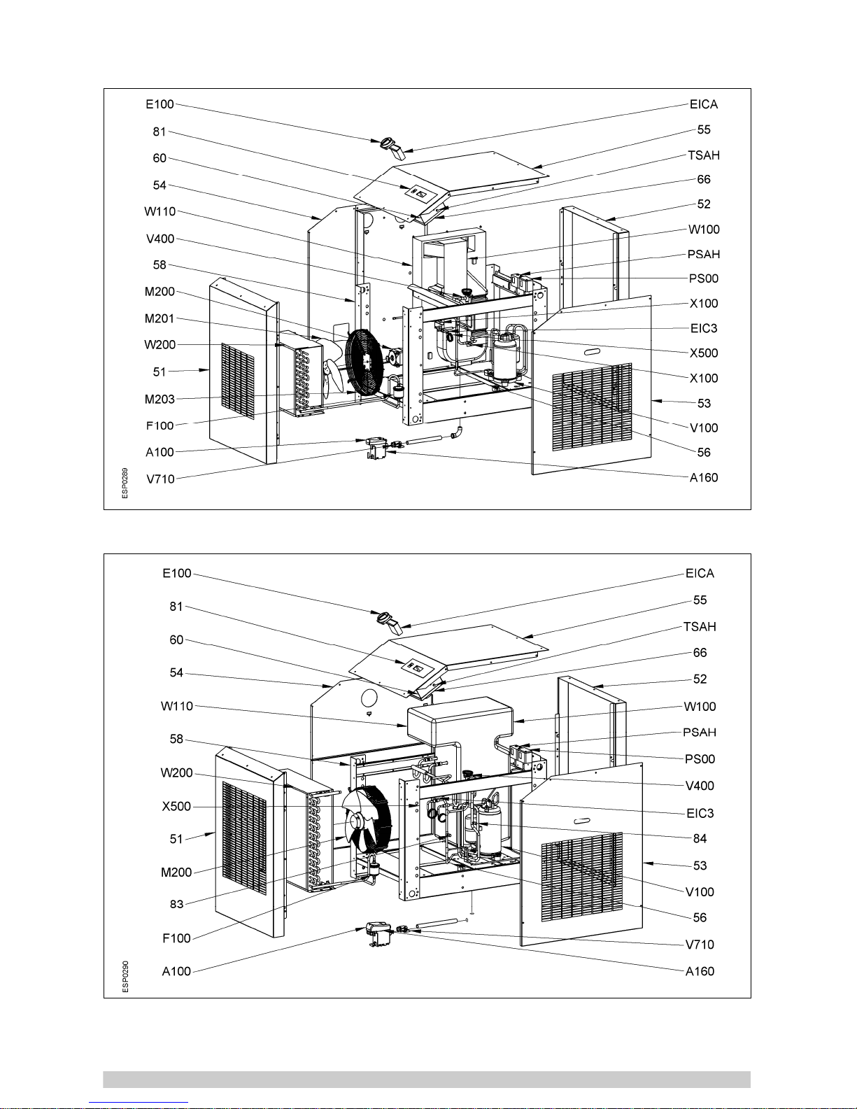
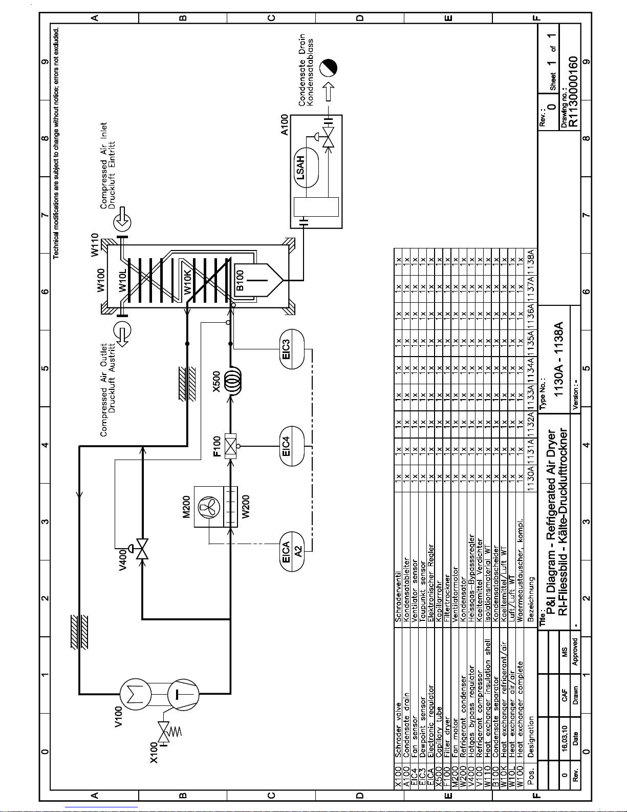
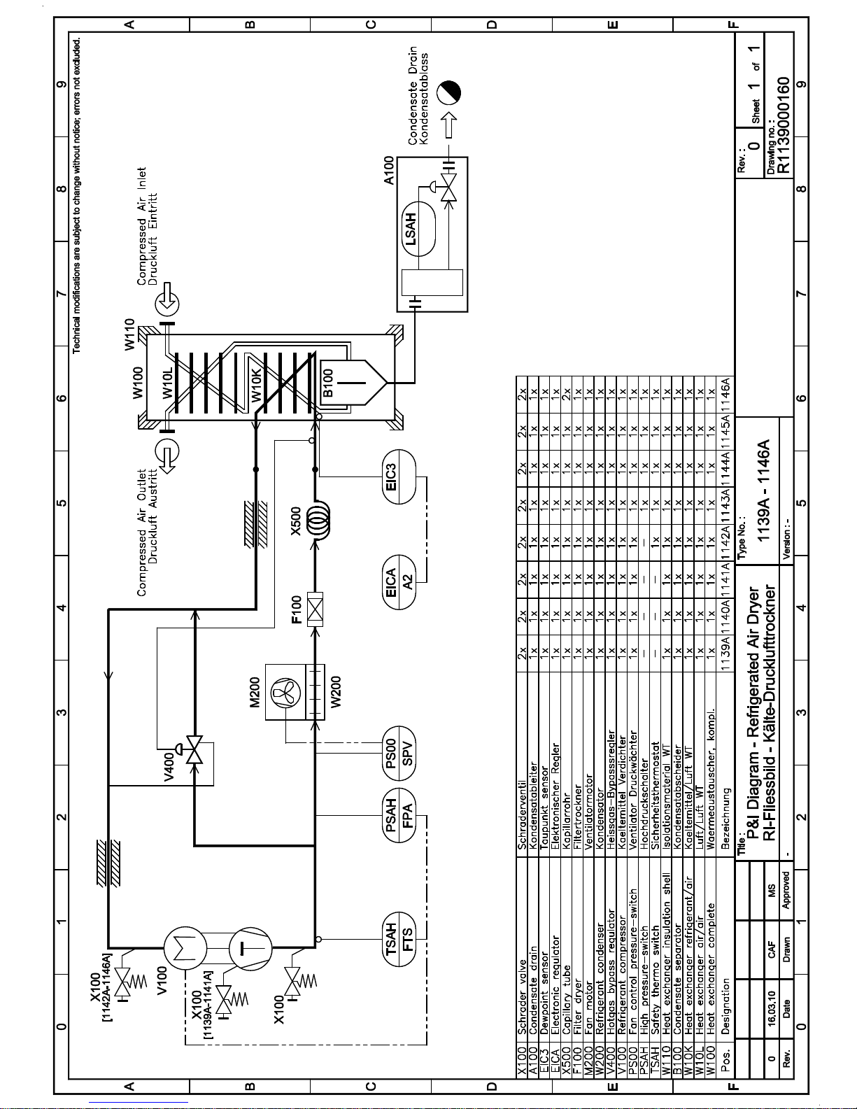
APX 2 &
APX 4
W100
W10L
W10K
B100
W110
TSAH
PSAH
PS00
V100
V400
W200
M200
M201
M203
F100
X500
EIC3
Heat exchanger complete
Heat exchanger air/air
Heat exchanger refrigerant/air
Condensate separator
Heat exchanger insulation shell
Safety thermo-switch
Refrigerant high pres.-switch
Refrigerant pres.-switch Fan
Refrigerant compressor
Hot gas by-pass regulator
Refrigerant condenser
Fan (motor)
Fan blade
Fan grid
Filter drier
Capillary tube
DewPoint sensor
EIC4
V710
EICA
A100
E100
51
52
53
54
55
56
58
60
66
81
A160
X100
Fan sensor
Condensate drain service valve
Electronic regulator
Condensate drain – complete
Main switch
Front panel
Rear panel
Right lateral panel
Left lateral panel
Cover panel
Base plate
Support beam
Control panel
Cover control panel
Flow diagram sticker
Condensate drain – service unit
Schrader valve
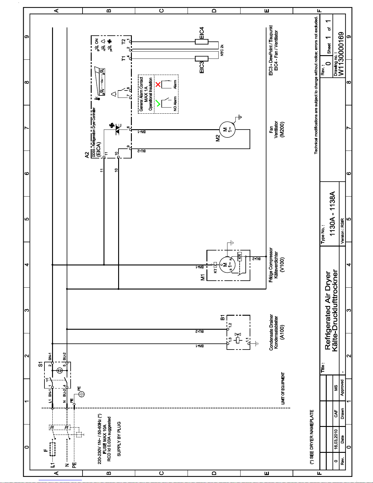
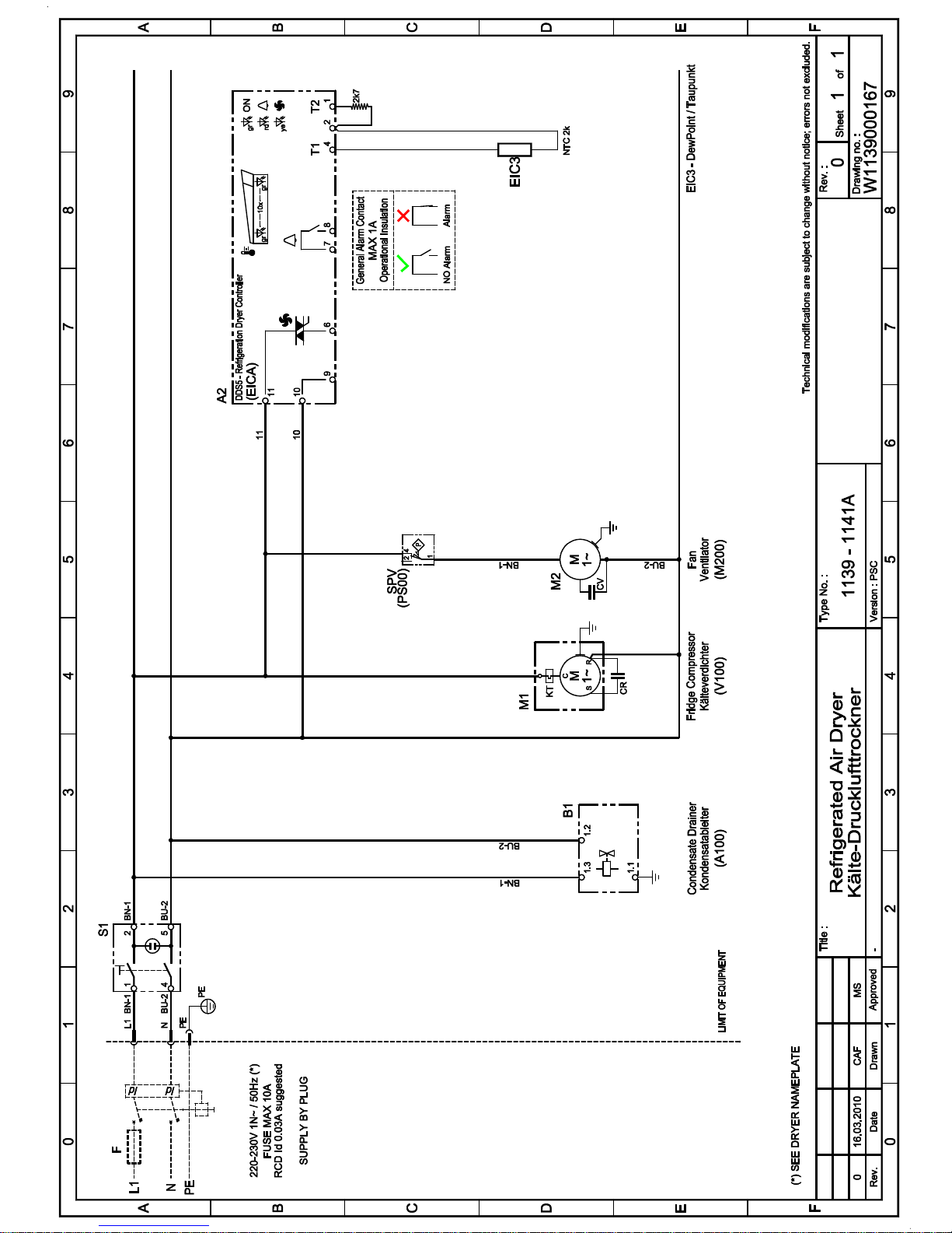
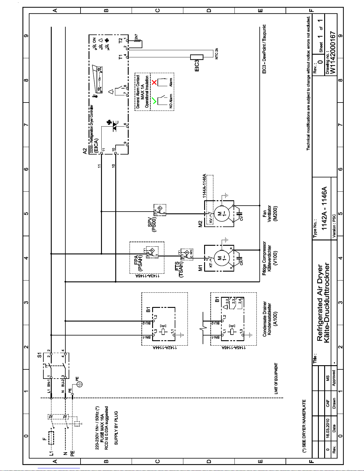
APX 3
S1
K
KT
KR
CS
CR
V
KV
CV
Main switch
Refrigerant compressor
Compressor thermal protection
Compressor starting relay
Compressor starting capacitor
Compressor run capacitor
Condenser fan
Fan thermal protection
Fan starting capacitor
TSAH
PSAH
PS00
A2
EIC3
EIC4
B1
Safety thermo-switch
Refrigerant high pres.-switch
Refrigerant pres.-switch Fan
DDS Electronic regulator
DewPoint sensor
Fan sensor
Condensate drainer
Page 27

APPENDIX
Page 28
07.2010
Apx 1.1 1130 A – 1137 A
Apx 1.2 1138 A – 1142 A
Page 29
07.2010
Apx 1.3 1143 A – 1145 A
Apx 1.4 1146 A
Page 30
07.2010
Apx 2.1 1130 A
Apx 2.2 1131 A – 1132 A
Page 31
07.2010
Apx 2.3 1133 A – 1137 A
Apx 2.4 1138 A
Page 32
07.2010
Apx 2.5 1139 A – 1141 A
Apx 2.6 1142 A
Page 33
07.2010
Apx 2.7 1143 A – 1145 A
Apx 2.8 1146 A
Page 34
Page 35
Page 36
Page 37
Page 38
Page 39
EG-Konformitätserklärung
EC declaration of conformity
Déclaration “CE” de conformité
EG-verklaring van overeenstemming
EU-konformitetsforklaring
FSN002003 Rev.03
DE - EN - FR
NL - DA
Hiermit enklären wir, dass die: Kälte-Drucklufttrockner
Herewith we declare that: Compressed air refrigeration dryer
Par la présente, nous déclarons, que la type de: Sécheur par réfrigération
Hiermde verklaren wij, dat de handel gebrachte machine: Perslucht koeldrogers
Hermed erklæres at produkttypen: Trykluft-køletørrer
Baureihe / Series / Série / Serie Typ / Type Artikel-Nr.:/Serial-No.:/ 97/23/EG – Kat. / Cat.
No Série/Serienummer:
DFX2 B10-230-xxx-01 1130A 1C Y 1130 B 0x 00 9 Art. 3 (3)
DFX4 B15-230-xxx-01 1131A 1C Y 1131 B 0x 00 9 Art. 3 (3)
DFX5 B15-230-xxx-01 1132A 1C Y 1132 B 0x 00 9 Art. 3 (3)
DFX7 B15-230-xxx-01 1133A 1C Y 1133 B 0x 00 9 Art. 3 (3)
DFX9 B15-230-xxx-01 1134A 1C Y 1134 B 0x 00 9 Art. 3 (3)
DFX11 B15-230-xxx-01 1135A 1C Y 1135 B 0x 00 9 Art. 3 (3)
DFX13 B25-230-xxx-01 1136A 1C Y 1136 B 0x 00 9 Art. 3 (3)
DFX15 B25-230-xxx-01 1137A 1C Y 1137 B 0x 00 9 Art. 3 (3)
DFX18 B32-230-xxx-01 1138A 1C Y 1138 B 0x 00 7 Art. 3 (3)
DFX23 B32-230-xxx-01 1139A 1C Y 1139 B 0x 00 7 Art. 3 (3)
DFX30 B32-230-xxx-01 1140A 1C Y 1140 B 0x 00 7 Art. 3 (3)
DFX36 B40-230-xxx-01 1141A 1C Y 1141 B 0x 00 7 I
DFX45 B40-230-xxx-01 1142A 1C Y 1142 B 0x 00 7 I
DFX55 B50-230-xxx-01 1143A 1C Y 1143 B 0x 00 7 I
DFX65 B50-230-xxx-01 1144A 1C Y 1144 B 0x 00 7 I
DFX75 B50-230-xxx-01 1145A 1C Y 1145 B 0x 00 7 I
DFX85 B50-230-xxx-01 1146A 1C Y 1146 B 0x 00 7 II
folgenden weiteren Richtlinien entspricht: 97/23/EG
conform with the following directives: 2004/108/EG
correspond aux disposition suivantes: 2006/95/EG
komt overeen met de volgende verdere richtlijnen: 2006/42/EG
videre retningslinier som anvendtes:
Angewendete harmonisierte Normen, insbesondere: ASME VIII Div.1 ; EN378-2 ; EN953 ;
Applied harmonized standards in particular: EN954-1 ; EN1050 EN1088 ;
Normes harmonisée utilisées, notamment: EN10028-3 ; EN12100-1 ;
Gebruike geharmoniseerde normen, in het bijzonder: EN12100-2 ; EN12451 ; EN50081-2 ;
Harmoniserade normen som anvendtes, i særdeleshed: EN50082-2 ; EN60204-1
Referenz Qualität Dokument: Fd – FSN002002 Rev.01
Reference quality document:
Référence Document de qualité:
Referentie kwaliteit document:
Reference kvalitet dokument:
Essen, 15.07.2010
Datum / Date / Datum / Dato Underschrift / Signature / Handtekening / Underskrift
(Bevollmächtigter / Authorized person / Fondé de pouvoir / Gevolmagtiegde / Fuldmægtig)
FST GmbH
Im Teelbruch 106, D-45219 Essen
Page 40

 Loading...