

Page 1

CONTENTS
1. GENERAL INFORMATION 2
1.1 Functional description 2
1.2 Use of the machine in safe conditions 2
2. SAFETY INFORMATION 3
2.1 General safety instruction 3
2.2 Equipment nameplate values 3
2.3 Information about remaining risks of the equipment 3
3. INSTALLATION 4
3.1 Acceptance, unpacking and handling 4
3.2 Storage and installation location 4
3.3 Unpacking 4
3.4 Installation 4
4. START-UP 5
5. MAINTENANCE 5
5.1 Weekly 5
5.2 Monthly 5
5.3 After 6 months 5
6. CONTROL PANEL 5
6.1 Icons description 6
6.2 Signalling Led description 6
6.3 Buttons function 6
6.4 Functions menu 7
6.5 Alarms 7
6.6 Programming 9
6.7 Set point display 13
6.8 Suggested maintenance function 13
6.9 Black out 13
6.10 Remote controls 13
7. TROUBLESHOOTING 14
8. CONDENSATE DRAIN 15
8.1 Maintenance 15
8.2 Integrated No Loss drain 15
8.3 No loss condensate drain 16
8.4 Maintenance and malfunctioning treatment 16
9. DECOMMISSIONING 17
10. SAFETY REQUIREMENTS 17
11. DAILY REGISTER 17
ATTACHMENTS TO THIS MANUAL 18
A) Refrigerant circuit 19
B) Electric circuit diagram 22
C) Technical data sheet 38
D) Correction factors 41
E) Dryer dimensions 41
F) Basic spare parts 44
DMN FST Kaeltetrockner DFLO150-1360 (Rev-06) –EN-20121100
OPERATORS MANUAL
Direct expansion compressed air dryers
Models
DFLO 150
DFLO 180
DFLO 225
DFLO 270
DFLO 360
DFLO 420
DFLO 530
DFLO 600
DFLO 680
DFLO 880
DFLO 1000
DFLO 1200
DFLO 1360
Page 2
Introduction
This manual is an integral part of the dryer you bought, and must remain with the machine even if this will be resold.
It is highly recommended that the qualified*personnel for installation maintenance and/or control will fully comply with the contents of
this manual and the prevention and safety rules in force in the country where the system will be used. In this way, not only the usage of
the machine will be rational, but also the service will result cost effective.
In case your dryer will present any kind of problem, please contact your local authorized FST distributor.
Please note that, when necessary, the use of original spare parts will ensure efficiency and long duration to your dryer.
Due to the continuous technological evolution, FST reserves the right to modify the specifications contained in this manual without
giving previous notice.
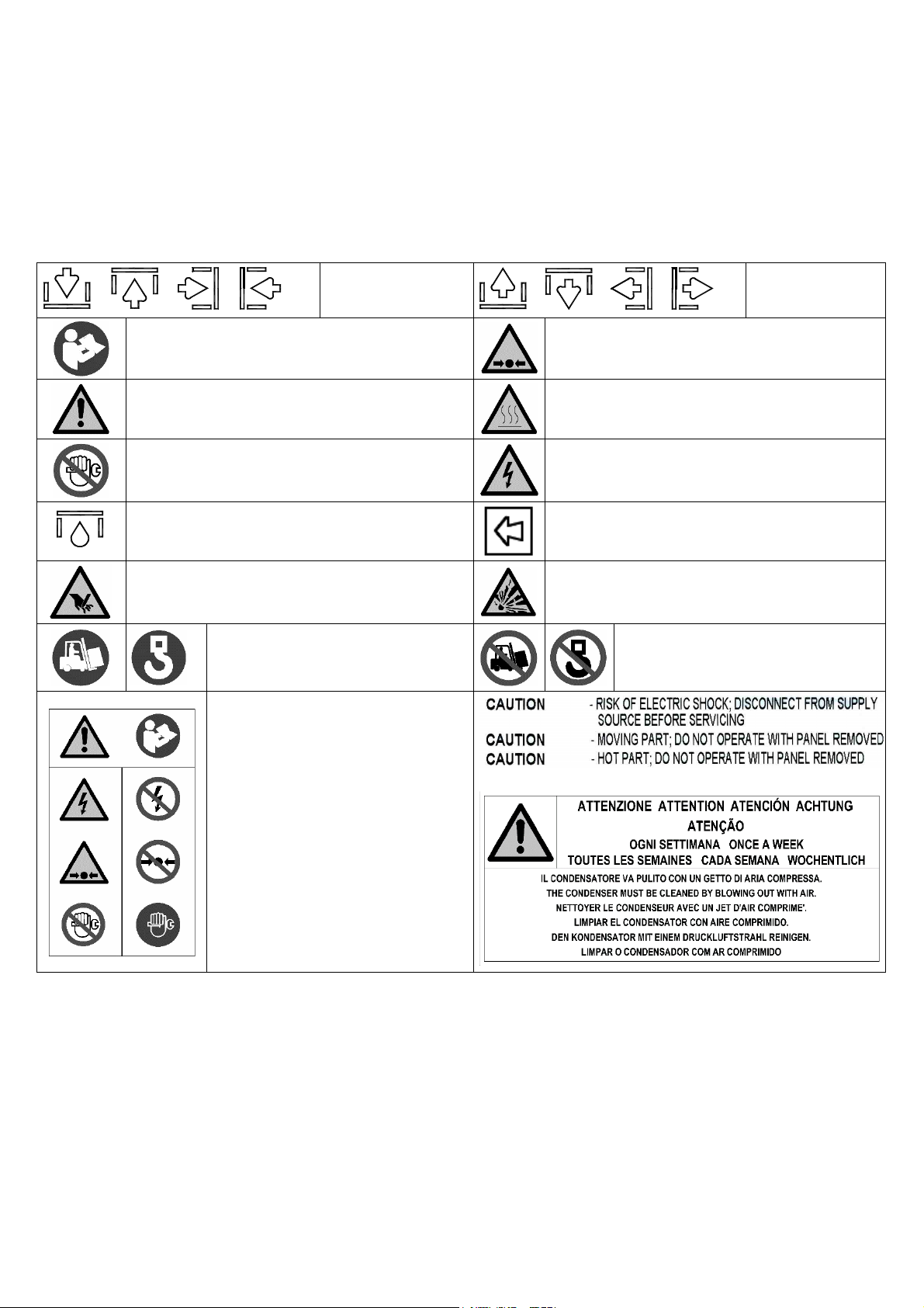
Symbols and labels used in the manual and on the dryer
o o o
Air inlet
Read the Operators manual before attempt to start up
the machine and to perform any service operation on
the dryer.
Pay particular attention to the indications preceded by
these symbols.
Installation, maintenance, and/or control operations
preceded by these symbols must be performed
exclusively by qualified personnel*.
Condensate drain point.
Pay particular attention to the risk of moving parts
Lifting point.
Attention: Before performing any
maintenance operation on this
machine, do not forget to disconnect
the electric supply, to completely
discharge air pressure, and to refer to
the Operators manual
o o o
Air outlet
Pay particular attention to components or systems
under pressure.
Pay particular attention to hot surfaces.
Pay particular attention to the risk of electric
shock.
Rotation direction of the fan.
Explosion risk.
Don’t lift from this point.
* Qualified personnel must be trained and certified in accordance with local laws and regulations.
Warranty
The Company warrants that the equipment manufactured by it and delivered hereunder will be free of defects in material and
workmanship for a period of twelve months from the date of placing the Equipment in operation or eighteen months from the date of
shipment from the factory, whichever shall first occur. The Purchaser shall be obligated to promptly report any failure to conform to this
warranty, in writing to the Company in said period, whereupon the Company shall, at its option, correct such nonconformity, by suitable
repair to such equipment or, furnish a replacement part F.O.B. point of shipment, provided the Purchaser has stored, installed,
maintained and operated such Equipment in accordance with good industry practices and has complied with specific recommendations
of the Company. Accessories or equipment furnished by the Company, but manufactured by others, shall carry whatever warranty the
manufacturers have conveyed to the Company and which can be passed on to the Purchaser. The Company shall not be liable for any
repairs, replacements, or adjustments to the Equipment or any costs of labor performed by the Purchaser or others without Company's
prior written approval.
The effects of corrosion, erosion and normal wear and tear are specifically excluded. Performance warranties are limited to those
specifically stated within the Company's proposal. Unless responsibility for meeting such performance warranties are limited to
specified tests, the Company's obligation shall be to correct in the manner and for the period of time provided above.
DMN FST Kaeltetrockner DFLO150-1360 (Rev-06) –EN-20121100
1
Page 3
THE COMPANY MAKES NO OTHER WARRANTY OR REPRESENTATION OF ANY KIND WHATSOEVER, EXPRESSED OR
IMPLIED, EXCEPT THAT OF TITLE, AND ALL IMPLIED WARRANTIES OF MERCHANTABILITY AND FITNESS FOR A
PARTICULAR PURPOSE, ARE HERBY DISCLAIMED.
Correction by the Company of nonconformities whether patent or latent, in the manner and for the period of time provided above,
shall constitute fulfillment of all liabilities of the Company for such nonconformities whether based on contract, warranty negligence,
indemnity, strict liability or otherwise with respect to or arising out of such Equipment.
The Purchaser shall not operate Equipment which is considered to be defective, without first notifying the Company in writing of its
intention to do so. Any such use of Equipment will be at Purchaser's sole risk and liability.
Note that this is FST standard warranty. Any warranty in force at the time of purchase of the equipment or negotiated as part of the
purchase order may take precedence over this warranty.
1. GENERAL INFORMATION
1.1 Functional description
FST refrigerated air dryers remove moisture from compressed air. Moisture is detrimental to pneumatically operated appliances,
controls, instruments, machinery and tools.
Compressed air enters the patented aluminum heat exchanger where it is cooled down to the dew point temperature in two different
stages: In the first air/air sector compressed inlet air is cooled thanks to the colder compressed air coming out counterflow from the
condensate separator. In the second refrigerant / air sector, compressed air temperature is further lowered to the dew point
temperature. During this two stages almost all the oil and water vapours contained in compressed air are condensed to liquid and
successively be separated from the compressed air in the condensate separator and drained out by the automatic drain. At this point
the obtained cold air re-enters counterflow the initial air / air exchanger and it is reheated by the inlet hot air with the consequence of
energy recovering and also reduction of the relative humidity contained in the outflowing air.
This dryer can be easily installed into various pneumatic systems in which dry air is required or desired. Please refer to Principles of
Operation for complete operating details.
The dryer comes provided with all the control, safety and adjustment devices, therefore no auxiliary devices are needed.
A system overload not exceeding the maximum operative limits can worsen the operational performance of the dryer (high
dew point), but it will not affect its safety.
The electric diagram (attachment B) shows the minimum protection degree IP 42.
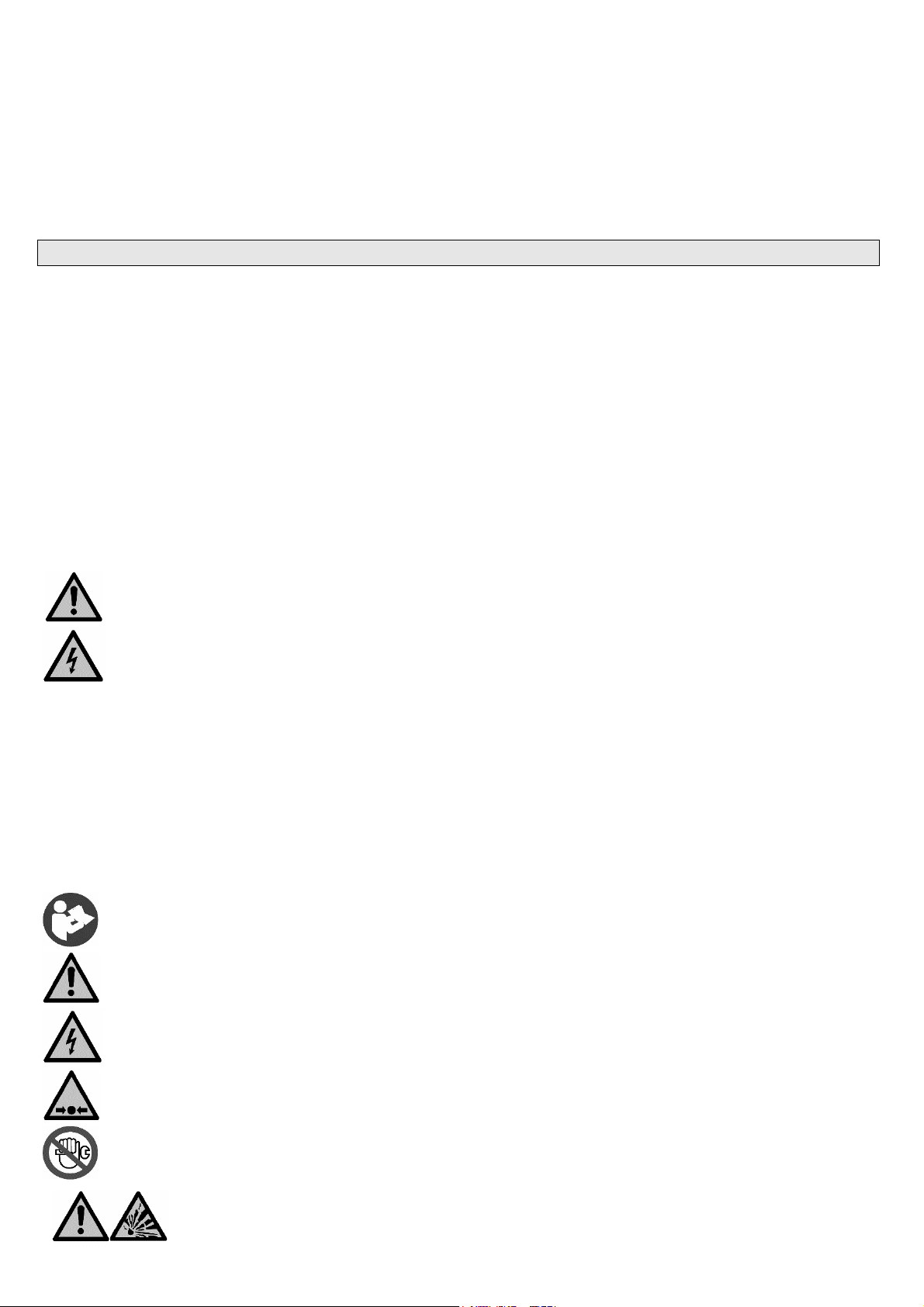
Improper grounding can result in electrical shock and can cause severe injury or death.
This product must be connected to a grounded, metallic, permanent wiring system or an equipment-grounding terminal or
lead on the product.
All grounding must be performed by a qualified electrician and comply with national and local electrical codes.
In the event of an electrical short circuit, grounding reduces the risk of electric shock by providing an escape wire for the
electric current.
Ground must be established with a bare grounding wire sized according to the voltage and minimum branch circuit
requirements.
Ensure good bare metal contact at all grounding connection points, and ensure all connections are clean and tight.
Check grounding connections after initial installation and periodically thereafter to ensure good contact and continuity has
been maintained.
Check with a qualified electrician or service technician if the grounding instructions are not completely understood, or if in
doubt as to whether the product is properly grounded.
1.2 Use of the machine in safe conditions
This system has been designed and manufactured in compliance with the European safety directive in force and UL/ULC, therefore
any installation, use and maintenance operations must be performed respecting the instructions contained in this manual.
Because an air dryer is pressurized and contains rotating parts, the same precautions should be observed as with any piece of
machinery of this type where carelessness in operation or maintenance could be hazardous to personnel. In addition to obvious safety
rules that should be followed with this type of machinery, safety precautions as listed below must be observed.
1. Only qualified personnel shall be permitted to adjust, perform maintenance or repair this air dryer.
2. Read all instructions completely before operating unit.
3. Pull main electrical disconnect switch and disconnect any separate control lines, if used, before attempting to
work or perform maintenance on the unit.
4. Do not attempt to service any part while machine is in an operational mode.
5. Do not attempt to remove any parts without first relieving the entire air system of pressure.
6. Do not attempt to remove any part of the refrigeration system without removing and containing refrigerant in
accordance with the EPA and local regulations.
7. Do not operate the dryer at pressures in excess of its rating.
8. Do not operate the dryer without guards, shields and screen in place.
9. Inspect unit daily to observe and correct any unsafe operating conditions.
This dryer is designed to work only with compressed air. For a different use, please contact your
distributor FST.
DMN FST Kaeltetrockner DFLO150-1360 (Rev-06) –EN-20121100
2
Page 4
2.0 SAFETY INFORMATION
MAWP
Freon HFC
2.1 General safety instruction
SAFETY INFORMATION
This dryer has been designed and manufactured in accordance with the European safety directive
2006/42/CE Machine Directive
2014/30/EU Electromagnetical compatibility Directive
2014/68/EU PED Directive
According to PED Directive, this plant is supplied with safety devices on the frigorific circuit, calibrated according to the
under mentioned specifications.
The working life of such equipments is expected between 10 and 20 years.
Any installation, use and maintenance operations must be done according to the instructions contained in this manual and in
accordance to the national rules.
Any cleaning/maintenance operation which needs access to the dryer must be carried out by qualified and export personnel
who must be aware of all necessary precautions.
The machine has been designed and manufactured to be used in conformity to the following specifications.
In case of different use of the machine or not in conformity to this manual, the Manufacturer can’t be accused of any
responsibility.
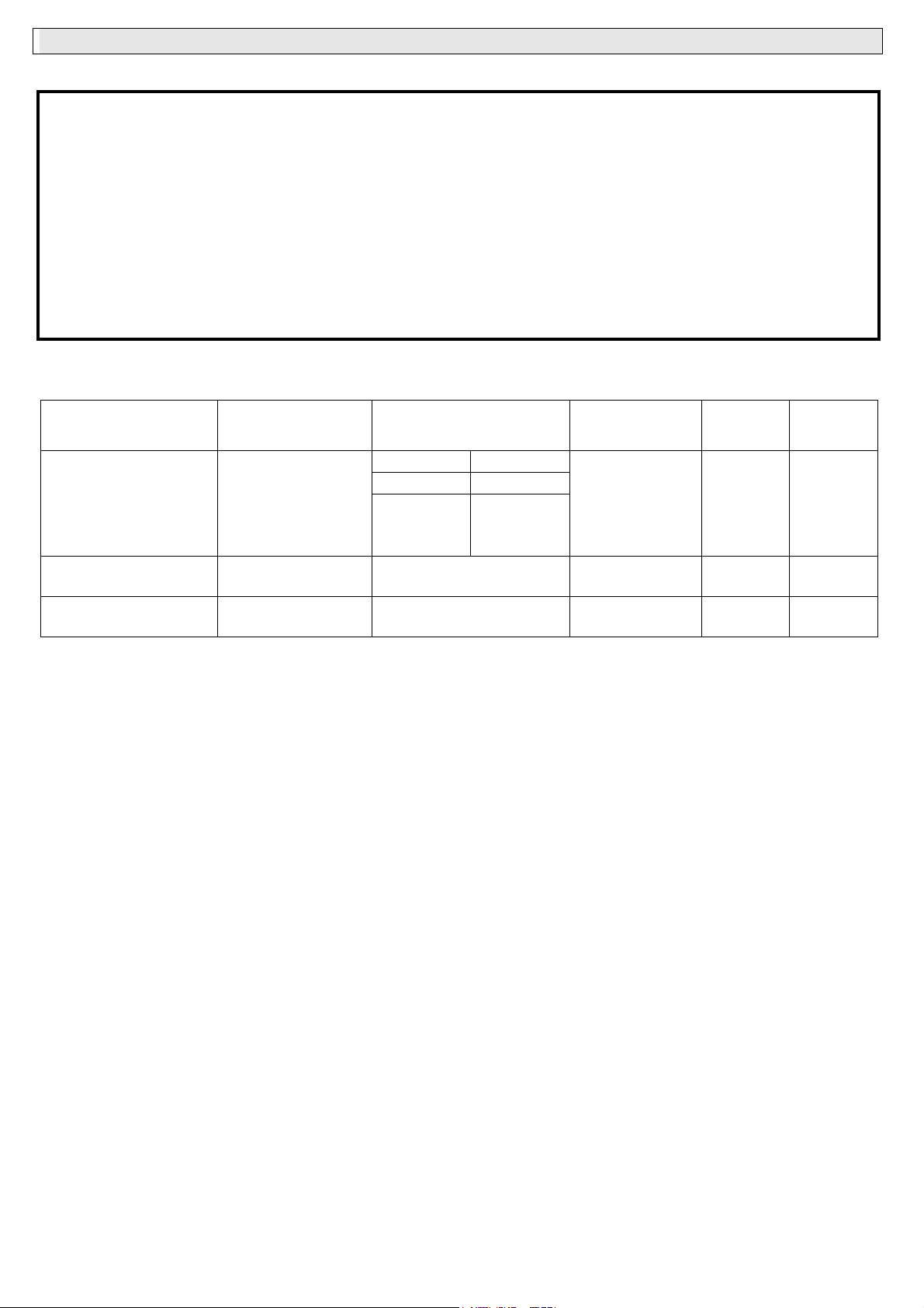
2.2 Equipment nameplate values
(Nameplate values extracted from Calculation data sheet)
Fluid Circuit Side Press. Max. Amm. Safety devices set Work. Temp Design Temp
"PS" (bar rel) (bar rel) (°C) (°C)
Ambient 55°C Ambient 43°C
(R507, R407c, R134a, R404a)
Compressed air Compress. Air Side min 0
Ambient air Ventilation side Atm. ( Not Appl.) min 5° min -15°
max +55° max. +55°
* - Safety Pressure switch Cat IV PED, Manual reset
Welding Joints Coefficient
Tickness allowance c 0 mm ( For copper )
(Not required for surfaces in contact with freon - EN 14276-1) c 1 mm ( For carbon steel )
Manufacturer design code 717.0012.01.00 Rev.09
Essential Safety Requirements ON10.0010.02 Rev.01
Manufacturer Working Procedure PO 08.2 Rev.01
Assembly classification according 2014/68/EU Cat. II
Evaluation Module according 2014/68/EU Mod. A1
PED Notified Body number 0474
2.3 Information about remaining risks of the equipment
Fire:
This equipment, in accordance to EN-378-2, isn’t supplied with freon drain safety valve.
In case of fire it is preferable to use fire extinguishers or extinction systems basically composed of powder or foam or carbon dioxide: it is possible to
cool the equipment thanks to nebulized water.
Avoid the massive use of water because, in case of freon gas leak, the chemical reaction can cause caustic effects, even if small.
In any case it is necessary to cool down the ambient and/or the equipment’s temperature and before any intervention wait until the temperature has
been reduced.
Therefore it is preferable to insert this equipment into the Fire Prevention and Factory Safety Plan.
Arrange adequate actions capable to prevent and fight the possible risk.
Dispersion of freon gas in the ambient:
the refrigerant means is toxic only if inhaled at high concentration: it is necessary to provide an adequate ventilation in the room where the equipment
is installed.
In any case check the scheme showing the values and the risk sentences.
Excessive pressure on the compressed air side:
this equipment isn’t supplied with safety devices on the compressed air side.
The safety devices on the compressed air side must be carried out by the installer.
Such devices will have to be carried out according to the applicable National Norms and to the limits mentioned in this Manual.
Ozone layer deterioration:
The adoption of HFC freon reduce to the minimum ozone layer deterioration and greenhouse effect.
Low press. -LP
High Press. -HP
High Press. WATER -HP
20 20
31 31
30 30
max. 14
z 0,7
See ATTACHMENTS
TO THIS MANUAL
C) Technical data
(Customer care)
sheet
(Table 5.6-1)
R134a R407c R404a, R507
min -10° min -15°
max +120° max +120°
max +120° max +120°
min 0° min 0°
max +60° max +60°
DMN FST Kaeltetrockner DFLO150-1360 (Rev-06) –EN-20121100
3
Page 5
3.0 INSTALLATION
3.1 Acceptance and handling
Upon receiving your FST air dryer, please inspect the unit closely. If rough handling is detected, please note it on your delivery receipt,
especially if the dryer will not be uncrated immediately. Then obtain the freight carrier's signed agreement to any noted damages: this
is a precondition for any insurance claims by the customer.
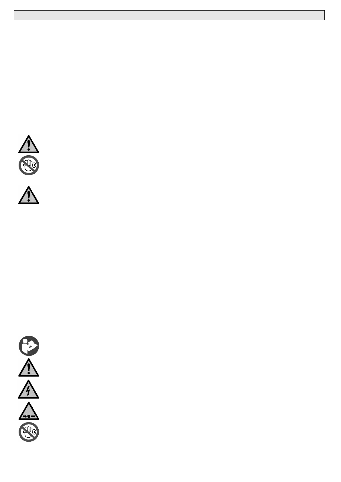
It is mandatory to keep the dryer always in vertical position, as indicated by the symbols present on the packaging. For handling, use
devices having sufficient capacity for the weight of the machine.
Remove the packaging after having positioned the dryer in the installation site. For unpacking, refer to section 3.3.
Under no circumstances should any person attempt to lift heavy objects without proper lifting equipment (i.e., crane, hoist, slings or fork
truck). Lifting any unit without proper lifting equipment, may cause serious injury. Use fork lift channels where provided.
3.2 Storage and installation location
If not in use, the dryer can be stored in its packaging in a dust free and protected site between 32°F (0°C) and 120 °F (50 °C), and a
specific humidity not exceeding 90 %. Should the stocking time exceed 12 months, please contact your local FST authorized distributor.
If the dryer is not used, it will be placed in a site with the following conditions:
The machine must be protected from atmospheric agents and not directly exposed to sun light.
A seating base flat and capable to hold the weight of the machine.
Ambient temperature complying with the nominal data of the dryer.
The dryer should be located in a clean area, without forced air draft that can affect the fan control system.
Make sure to leave sufficient clearance (40 inches, 1 m) around the dryer in order to allow an adequate cooling
of the machine and for maintenance and/or control operations.
The incoming air must be free from smoke or flammable vapours which could lead to explosion or fire risks.
3.3 Unpacking
The packaging is made of carton or of cellophane. We recommend that you keep the original packaging for the device in case it has to
be transported to another location or sent to a service center. Dispose the various packaging materials in compliance with the relevant
rules locally in force.
• unpack the device, removing the strapping from the carton. Always wear safety gloves when using scissors or other tools to cut the
straps or the cellophane;
• remove the carton or the cellophane;
• in case it’s necessary another handling of the device, refer to section 3.1;
• remove the pallet (if present);
• remove the operating manual, accessories and key from the device.
3.4 Installation
Before attempting any installation operation, make sure that
No parts of the air system are under pressure.
No parts of the system are electrically powered.
Tubing to be connected to the dryer are free of impurities.
The pipes to be connected to the dryer does not weigh on the device.
All interconnecting piping has been tightened.
After having verified the points listed above, you can proceed to the installation of the machine.
1. Connect the dryer to the compressed air lines. If not already existing, we suggest to install a by-pass allowing to
isolate the machine from the plant, thus to facilitate eventual maintenance operations.
2. Perform the electrical connection in accordance with any local laws and regulations after reviewing the dryer
electrical specifications and wiring diagram.
3. Check the condensate drainage assembly, and connect the drain flexible hose to the draining line, keeping in
mind that the condensate separated by the dryer may contain oil, therefore, in order to dispose of it in
compliance with the local rules in force, we suggest installing a water-oil separator having adequate
capacity.
4. Power the dryer after having checked that the nominal voltage and line frequency are constant and matching the
nominal values of the machine. The user must provide the installation with an adequate line protection
and a ground terminal complying with the electrical rules locally in force.
DMN FST Kaeltetrockner DFLO150-1360 (Rev-06) –EN-20121100
4
Page 6
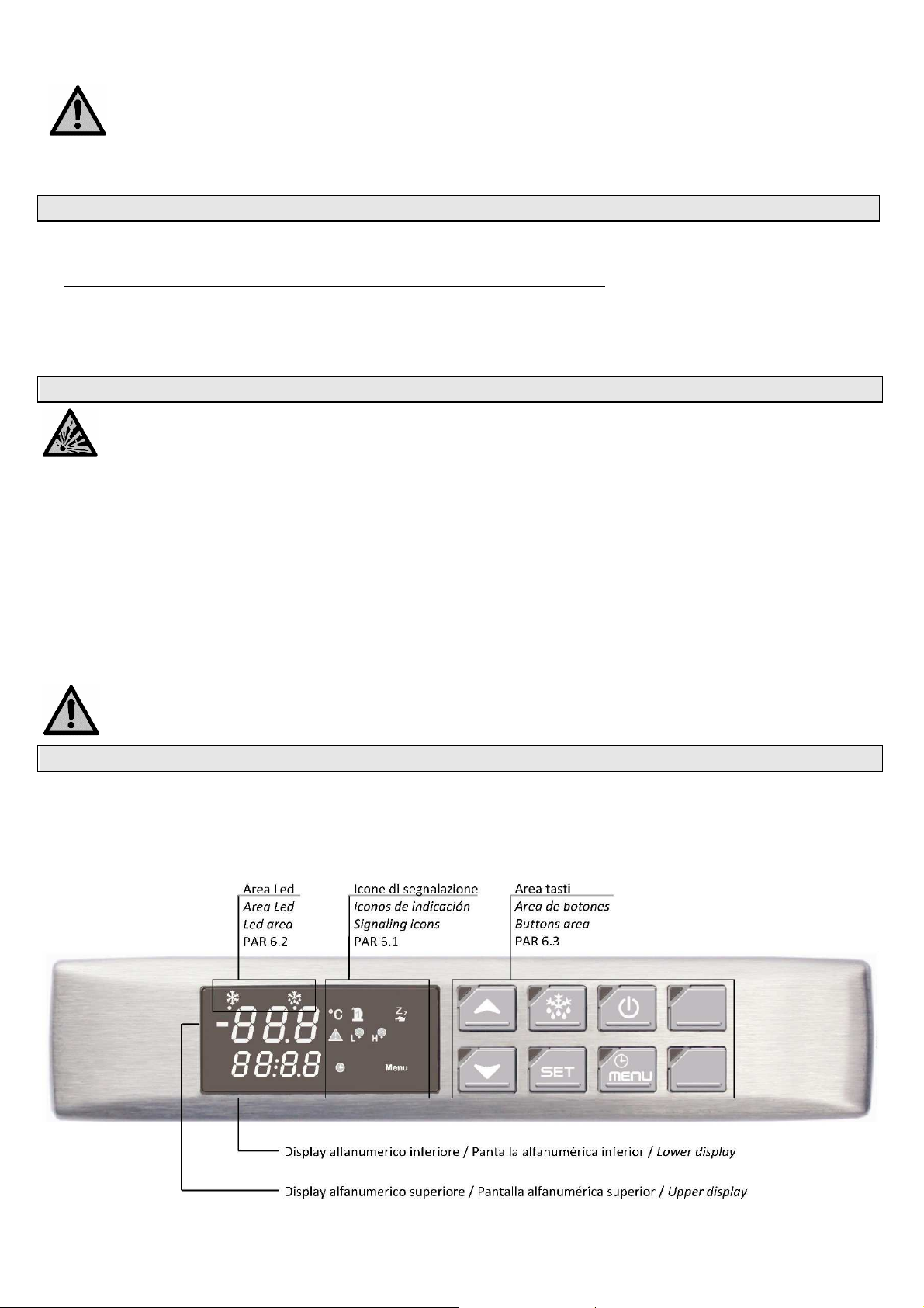
In order to optimise the use of the dryer, we suggest to place it in such a way that all the control instruments of the
machine will result easily visible.
A suitably sized prefilter must be installed before the dryer. Failure to install and maintain a proper prefilter will
void the dryer warranty. The rating for this filter must be at least 10 micron.
It is necessary for the user to install a protective device (a safety accessory) to protect the equipment under
pressure from the risk of exceeding the maximum allowable pressure (PS); it is necessary to install a protective
device to protect the equipment at high temperature from the risk of exceeding the maximum allowable
temperature.
4.0 START-UP
• Make sure that intake and outtake valves are closed, switch on the devices (1S1).
• TO START THE DRYER IT IS NECESSARY TO PRESS AND HOLD THE ON/OFF BUTTON FOR AT LEAST FOR 3 SECONDS
• THERE IS A DELAY BEFORE THE DRYER WILL START AFTER THE DRYER IS TURNED ON, IN ORDER TO WARM UP COMPRESSOR OIL.
• IF THE UNIT FAILS TO START MAKE SURE THAT PHASES ARE CONNECTED CORRECTLY.
• Allow some minutes for the dryer to run at full speed, i.e. until the displayed value on the temperature display is within the field of good operation
(about 3°C).
• Now open the outlet air valve and then open gradually the intake air valve. In this way, the plant is gradually pressurized.
• If the plant is overloaded over the max. use limits (see technical data), the dryer's performance will be remarkably lower but safety will not be in
danger.
5.0 MAINTENANCE
Attention! Perform pressure test with inert gases only (helium, nitrogen).
5.1 Weekly
Check visually if the condensate is properly drained.
5.2 Monthly
Clean prefilter to remove any possible dirt on the inner filtering element.
Perform the following after stopping the compressed air flow by closing the intake and outtake valves.
5.3 After 6 months
Isolate the machine before performing the following.
According to the room temperature quality and when summertime begins, clean the condenser to remove possible scales or deposits the might
decrease its performance.
Check that the compressor power consumption values fall within the range detailed on the machine plate (see compressor product label).
In case of replacement of one or more components of the device, disposed it along the eventual packaging of the
replacement part, as reported in section 9.0.
6.0 CONTROL PANEL
The machines in this series are equipped with an electronic controller for the adjustment of the operating parameters. Adjustments can
be made using the digital panel, located on the dryer’s front panel. Please note that the SET POINT & other control parameters
have been optimized and factory set. Although the set point value can be displayed, the ability to alter these factory settings
via the digital interface on the front panel has been removed to eliminate the possibility of unit damage caused by improper
settings.
fig.1 - Control panel
DMN FST Kaeltetrockner DFLO150-1360 (Rev-06) –EN-20121100
5
Page 7
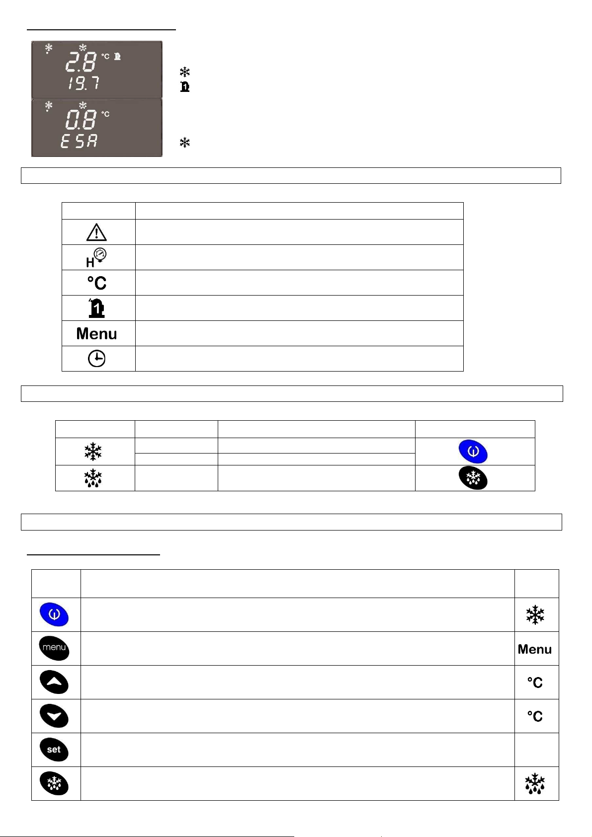
Normal conditions read - out
6.1 Icons description
ICON DESCRIPTION
At normal operating conditions, if no alarms are present, the upper display shows the DEW
POINT temperature, the lower display shows the AMBIENT TEMPERATURE.
Led (dryer ON) is lighting.
icon (refrig. compressor ON) is lighting.
In anti-freezing condition, if no alarms are present, the upper display shows the DEW POINT
temperature, the lower display shows cyclingly ESA for 10sec and the AMBIENT
TEMPERATURE for 1sec.
Led (dryer ON) is lighting.
Generic Alarm
High / Low refrigerant discharge pressure Alarm (HP/LP)
Icon ON shows “Celsius degrees”
Icon OFF shows “Fahrenheit degrees”
Refrigerant compressor energized
(Blinking when start refrigerant compressor delay activated)
“Functions menu” activated
Icon connected to time parameters
(ON when in Functions or Programmation area)
6.2 Signalling Led description
SIMBOL STATUS DESCRIPTION BUTTON
ON Dryer energized
BLINKING Compressor oil warm up
ON
Condensate drain energie
(Not used with no loss discharger)
6.3 Buttons function
Single buttons function
SYMBOL DESCRIPTION
Activates or deactivates unit operation when pressed for 3 seconds (ON/OFF).
When deactivated, the OFF message is displayed.
When the dryer is switched off using this button all digital outputs are disconnected.
LED /
ICON
Allows entry the “Functions Menu”
Pressed during normal operation displays the compressor oil temperature.
When pressed during programming mode, it scrolls the parameters list or increases the displayed value.
Pressed during normal operating displays the refrigerant circuit suction pressure.
When pressed during programming mode, it scrolls the parameters list or decreases the displayed value.
Pushed and released shows on display the SET POINT value.
In programming mode selects a parameter or confirms a value.
When pressed for more than 3 seconds during the normal operating, it performs a test of the condensate
discharge valve. (Not used with no loss discharger)
DMN FST Kaeltetrockner DFLO150-1360 (Rev-06) –EN-20121100
6
Page 8
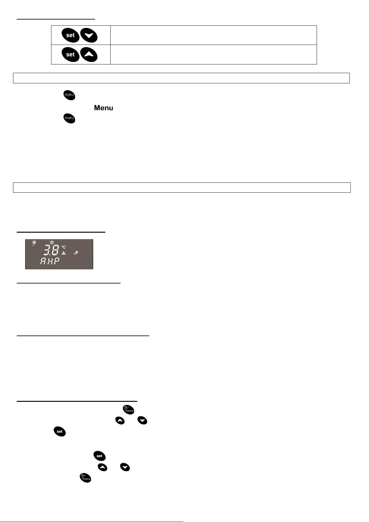
Buttons combinations
Enters the PARAMETER PROGRAMMING MENU
Exits the PARAMETER PROGRAMMING MENU
6.4 Functions menu
Press and release button to enter the Functions menu.
When in “Functions Menu” the icon is illuminated.
Press and release to close the Functions menu or wait 15 sec. (Automatic close).
Functions Menu allows to:
1. Show and reset the active alarms (“ALrM” function).
2. Show or reset the ALARM LOG (“ALOG” function).
3. Show and reset the energy saving counter (“ESA” function, not available).
4. Upload the parameters from the controller to the Hot Key (“UPL” function).
5. Show and reset the time running hour counters of refrigerant compressor (“C1Hr” function).
6.5 Alarms
The controller is able to recognize particular types of faults in the drying circuit. When this occurs, the display shows the required
information necessary to find out the cause.
The controller is programmed to recognize and display prealarms and alarms.
Alarm conditions read - out
When a fault is detected the Lower display shows a blinking alarm label and the correspondent
icon alternating with the temperature. The Upper display always shows the Dew Point
temperature.
Buzzer active.
Silencing the Buzzer (if present)
When an alarm is activated, the electronic board will emit an acoustic signal (buzzer).
The buzzer can be stopped in two ways:
- Automatically: when the alarm condition is recovered.
- Manually: push and release one of the keys of the controller; the buzzer is stopped even if the alarm is still active.
6.5.1 Prealarms and Alarms description
Prealarms show conditions of critical operation of the dryer, they will not stop the refrigerant compressor.
When this situation occurs it’s suggested to make the required maintenance to eliminate the prealarm condition.
Alarms means conditions of critical operation of the dryer for a determinate preset delay, normally they are preceded by a prealarm
signalling. Alarms stop the refrigerant compressor, except Pb2, Pb3 and Pb4.
When this situation occurs it’s necessary to make maintenance for recover the fault condition.
6.5.2 For display and reset an alarm
1. Enter the “FUNCTIONS MENU” ( button).
2. Find “ALrM” using the buttons and .
3. Push button to display the alarms:
- Lower display will show the code of the active alarm.
- Upper display will show “rSt” label if the alarm can be resetted or “NO” label if it is not resettable.
- To reset an alarm push
button when “rSt” label is lighted (at reset done the controller automatically skips to next alarm).
- Scroll all alarms by using and buttons.
4. Quit by pushing button or wait for automatic quit.
DMN FST Kaeltetrockner DFLO150-1360 (Rev-06) –EN-20121100
7
Page 9
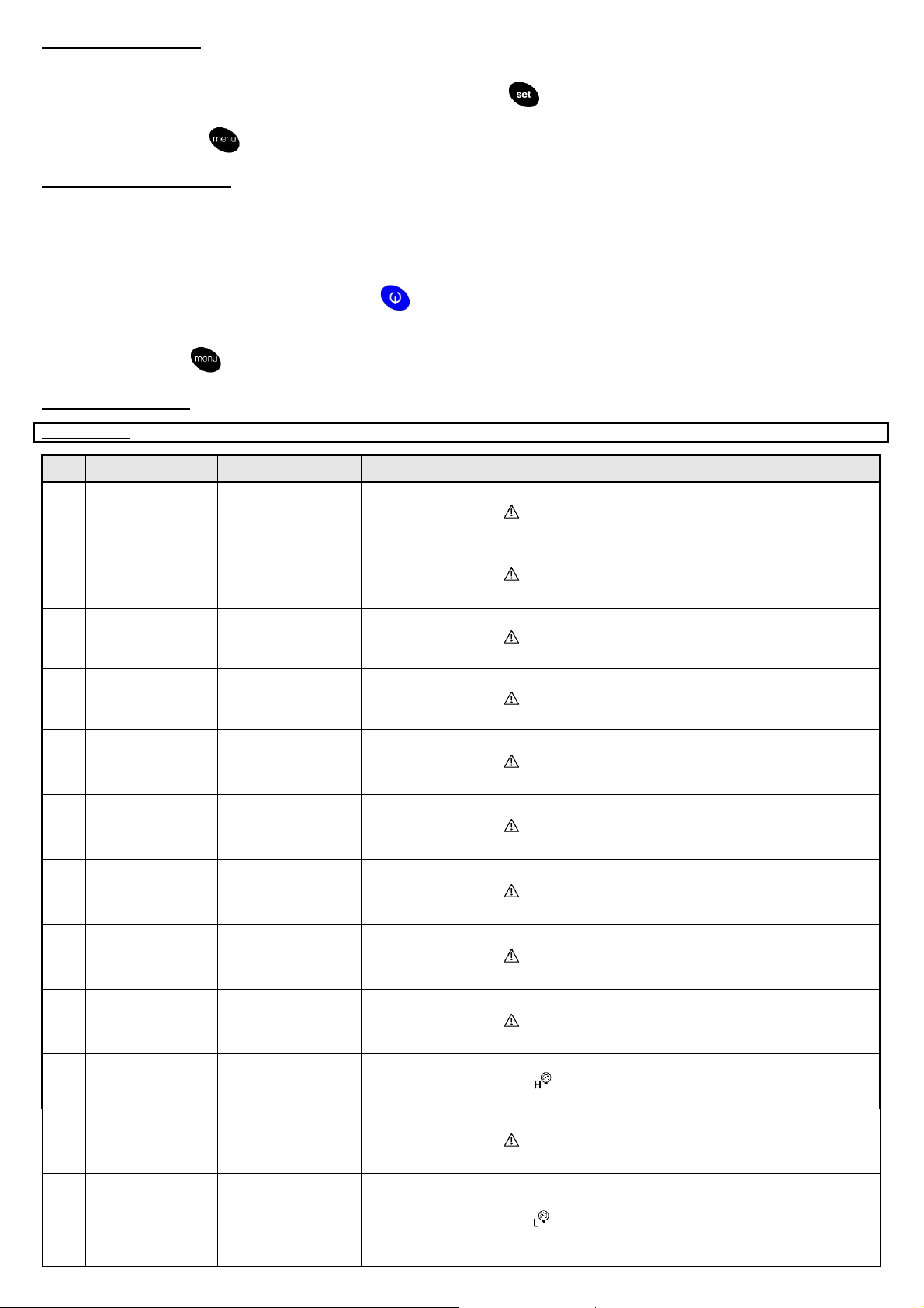
Resettable alarms
IMPORTANT:
ESA mode is NOT an alarm
, please refer to Par. 6.0
(Pb2) Air inlet
Dew Point temperature
Dew Point temperature
High inlet air
Inlet air temperature
Ambient temperature
Refrigerant circuit suction
Alarm relay activated
Manual
An alarm is defined resettable (rSt) when the generating cause disappears. These alarms can be directly resetted by the controller
proceeding as follows:
- Display the alarms following the above instructions, then push button when “rSt” label is lighted (at reset done the
controller automatically skips to next alarm, if present).
- Quit by pushing button or wait for automatic quit.
Not resettable alarms
An alarm is defined NOT resettable (NO) when the cause that produces it persists, these types of alarms can’t be directly reset by the
controller until the causes that produce them are eliminated.
When one of these alarms appear proceed as follows:
- Identify the alarm code shown on controller display.
- Follow indications on alarm table PAR. 6.5.3. to eliminate the alarm original cause.
- Reset the alarm using the procedure described on previous point.
- if the alarm persists, try to reset pushing button for 3 sec. stopping the operation process (label OFF shown on
controller display), then restart pushing the same button.
- If the alarm persists call your local FST distributor.
- Quit pushing button or wait for automatic quit.
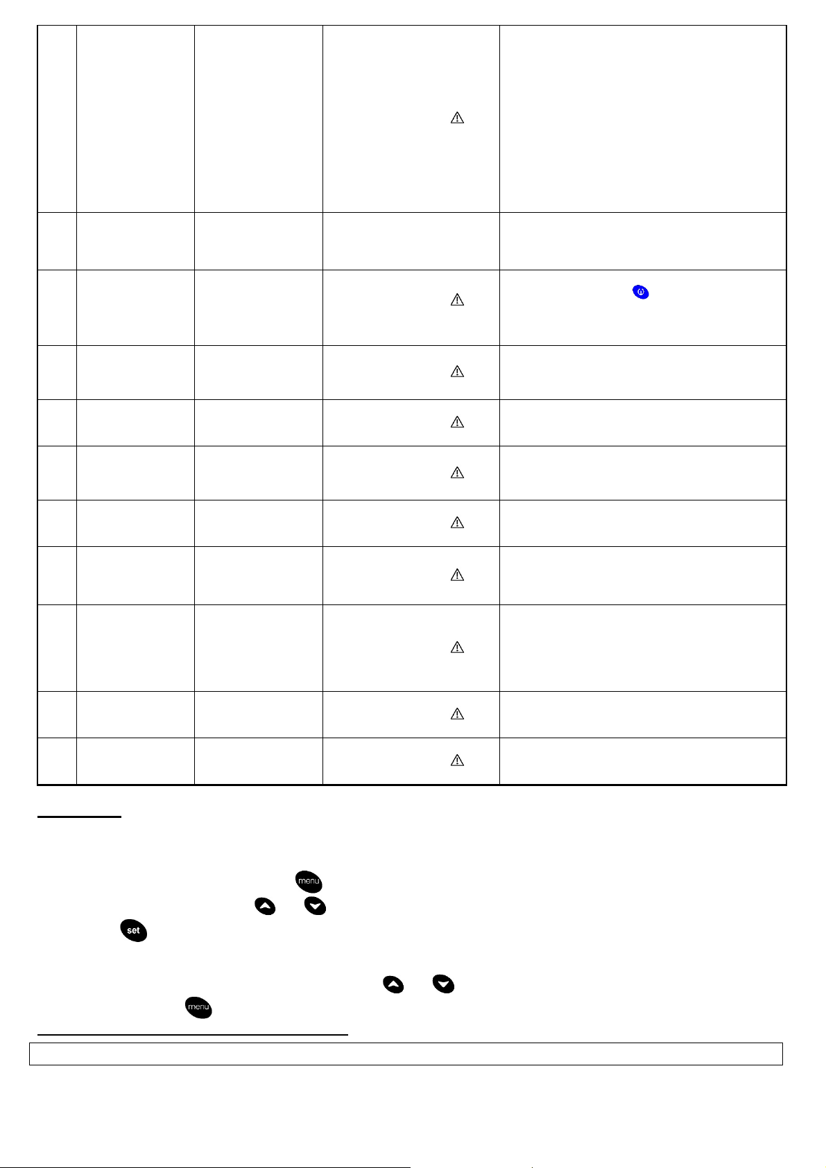
6.5.3 Alarm table
Label Meaning Cause / Origin Controller status Reset
(Pb1) Dew point probe
P1
alarm
temperature probe
P2
alarm Valid only if
CF05 =1
(Pb3) Ambient
P3
temperature probe
alarm
(Pb4) Refrigerant circuit
P4
suction temperature
probe alarm
Dew Point high
A1
temperature prealarm
(Pb1 probe)
Dew Point low
A2
temperature prealarm
(Pb1 probe)
temperature prealarm
A3
(Pb2 probe) Valid only
if CF05 =1
High ambient
A4
temperature pre-alarm
(Pb3 probe)
High refrigerant circuit
A5
suction temperature
prealarm (Pb4)
High/Low pressure
AHP
safety switch (HP/LP)
alarm (1P1 switch)
(1Q2) Fan thermal
AtFA
protection alarm
Missing, faulty probe or
resistance exceeding
value
Missing, faulty probe or
resistance exceeding
value
Missing, faulty probe or
resistance exceeding
value
Missing, faulty probe or
resistance exceeding
value
higher than the presetted
value
( PB1 > AL23 )
lower than the presetted
value
( PB1 < AL20 )
higher than the presetted
value
( PB2 > AL26 )
higher than the presetted
value
( PB3 > AL11 )
temperature higher than
the presetted value
( PB4 > AL29 )
High pressure switch
digital input activation
Digital input
activation
Alarm relay activated
General alarm icon lighted
Alarm code on display
Alarm relay activated
General alarm icon lighted
Alarm code on display
Alarm relay activated
General alarm icon lighted
Alarm code on display
Alarm relay activated
General alarm icon lighted
Alarm code on display
Alarm relay activated
General alarm icon lighted
Alarm code on display
Alarm relay activated
General alarm icon lighted
Alarm code on display
Alarm relay activated
General alarm icon lighted
Alarm code on display
Alarm relay activated
General alarm icon lighted
Alarm code on display
Alarm relay activated
General alarm icon lighted
Alarm code on display
High pressure alarm icon lighted
Alarm code on display
Alarm relay activated
General alarm icon lighted
Alarm code on display
Automatic
if the probe value recovers
If the alarm persists call your local FST distributor
Automatic
if the probe value recovers
If the alarm persists call your local FST distributor
Automatic
if the probe value recovers
If the alarm persists call your local FST distributor
Automatic
if the probe value recovers
If the alarm persists call your local FST distributor
Not necessary
Not necessary
Not necessary
Not necessary
Not necessary
Manual
Digital input deactivation then manual reset from Functions
menu.
Restart the (1Q2) thermal protection, then proceed with
manual reset from Functions menu.
If the alarm persists call your local FST distributor
Low pressure switch
ALP
(LP) alarm
(1P3 switch)
DMN FST Kaeltetrockner DFLO150-1360 (Rev-06) –EN-20121100
Low pressure switch
digital input activation
Alarm relay activated
Low pressure alarm icon lighted
Alarm code on display
Automatic
It becomes manual after AL02 activations / hour
Manual
Digital input deactivation then manual reset from Functions
menu.
8
Page 10
(1S2) High
Refrigerant
discharge temperature
Refrigerant
Automatic
if Pb1 < AL23
- AL24
button for 3 sec. stopping the
Alarm relay activated
Alarm relay activated
Manual
CF01= 0
-1-2-
3 e
Alarm relay activated
Alarm relay activated
alarm.
(KRC1) Refrigerant
compressor phase
AtCO
detection alarm
(available for
Digital input
activation
DFLO880 and above)
(1Q1) Refrigerant
compressor thermal
protection alarm
AMnC
compressor
suggested
Running hours >
CO14
maintenance alarm
High Dew Point
A10
temperature alarm
Low Dew Point
A20
temperature alarm
High inlet air
A30
temperature alarm.
Valid only if CF05 =1
High ambient
A40
temperature alarm
Valid only if CF05 =1
High refrigerant circuit
A50
suction temperature
prealarm
A1 with AL22 delay
A2 with AL19
delay
A3 with AL25
delay
A4 with AL13
delay
A5 with AL28
delay
EE EEPROM error alarm Memory data lost
Alarm relay activated
General alarm icon lighted
Alarm code on display
Alarm relay activated
Alarm code on display
Alarm relay activated
General alarm icon lighted
Alarm code on display
Regulation OFF
Alarm relay activated
General alarm icon lighted
Alarm code on display
General alarm icon lighted
Alarm code on display
Alarm relay activated
General alarm icon lighted
Alarm code on display
General alarm icon lighted
Alarm code on display
Alarm relay activated
General alarm icon lighted
Alarm code on display
(1S2) - Manual if the temperature returns into range of good
working, then proceed with manual reset from Functions
menu.
(1Q1) - Manual
Restart the (1Q1) thermal protection, then proceed with
manual reset from Functions menu.
After AL09 events in 1 hour and digital input not active, set
parameter AL10=0 to resume with reset procedure from
Functions menu.
If the alarm persists call our Aftersale service
Manual
Reset running hours from Functions menu.
(See PAR. 6.8)
Manual try to reset pushing
operation process (label OFF shown on controller display),
then restart pushing the same button.
If the alarm persists call your local FST distributor
Automatic
if Pb1 > AL20 + AL21
If the alarm persist call your local FST distributor
Automatic
if Pb2 < AL26 - AL27
If the alarm persists call your local FST distributor
Automatic
if Pb3 < AL11 – AL12
If the alarm persists call your local FST distributor
Automatic
if Pb4 < AL29 – AL30
If the alarm persists call your local FST distributor
Reset from Functions menu. If after Reset procedure alarm is
occurring again, the controller remains blocked : call your
local FST distributor
ACF2 Configuration alarm
FA02 =1-2,
without
condensing
probe control
Alarm relay activated
General alarm icon lighted
Alarm code on display
Automatic
After parameter proper debug.
If the alarm persists call your local FST distributor
configuration
ACF3 Configuration alarm
AFr Frequency alarm
Two digital inputs
having the same
function
The frequency of
power supply is
out of range
General alarm icon lighted
Alarm code on display
General alarm icon lighted
Alarm code on display
Automatic
After parameter proper debug.
Automatic
After the frequency becomes normal
If the alarm persists call your local FST distributor
Alarms Log
Alarms Log contains the last 50 alarms events detected by the controller. Each new alarm higher than this number will take
automatically the place of the oldest memorized. The read-out is ordered from oldest (01) to newest (50).
To read Alarms Log list proceed as follow:
1. Enter the “FUNCTION MENU” (Push button)
2. Select “ALOG” function using and .
3. Push button to display the Alarms Log:
- Lower display will show the code of an alarm.
- Upper display will show the progressive number of the same alarm.
- Scroll all alarms contained using and .
4. Quit by using the button or wait automatically quit.
N.B.: Alarms Log can be erased only with password.
6.6 Programming
The controller’s parameters are collected into aggregates, each identified by a label. This allows the user an easy access to the
interested parameters. the label is shown on the display.
On table 6.6.2 are indicated and described all labels and the correspondent programming parameters.
DMN FST Kaeltetrockner DFLO150-1360 (Rev-06) –EN-20121100
9
Page 11
STANDARD
DFLO
DFLO
ALL
-
5,0 -
1,5
ST
10,0
6,0
+1,0
+1,0
4 4
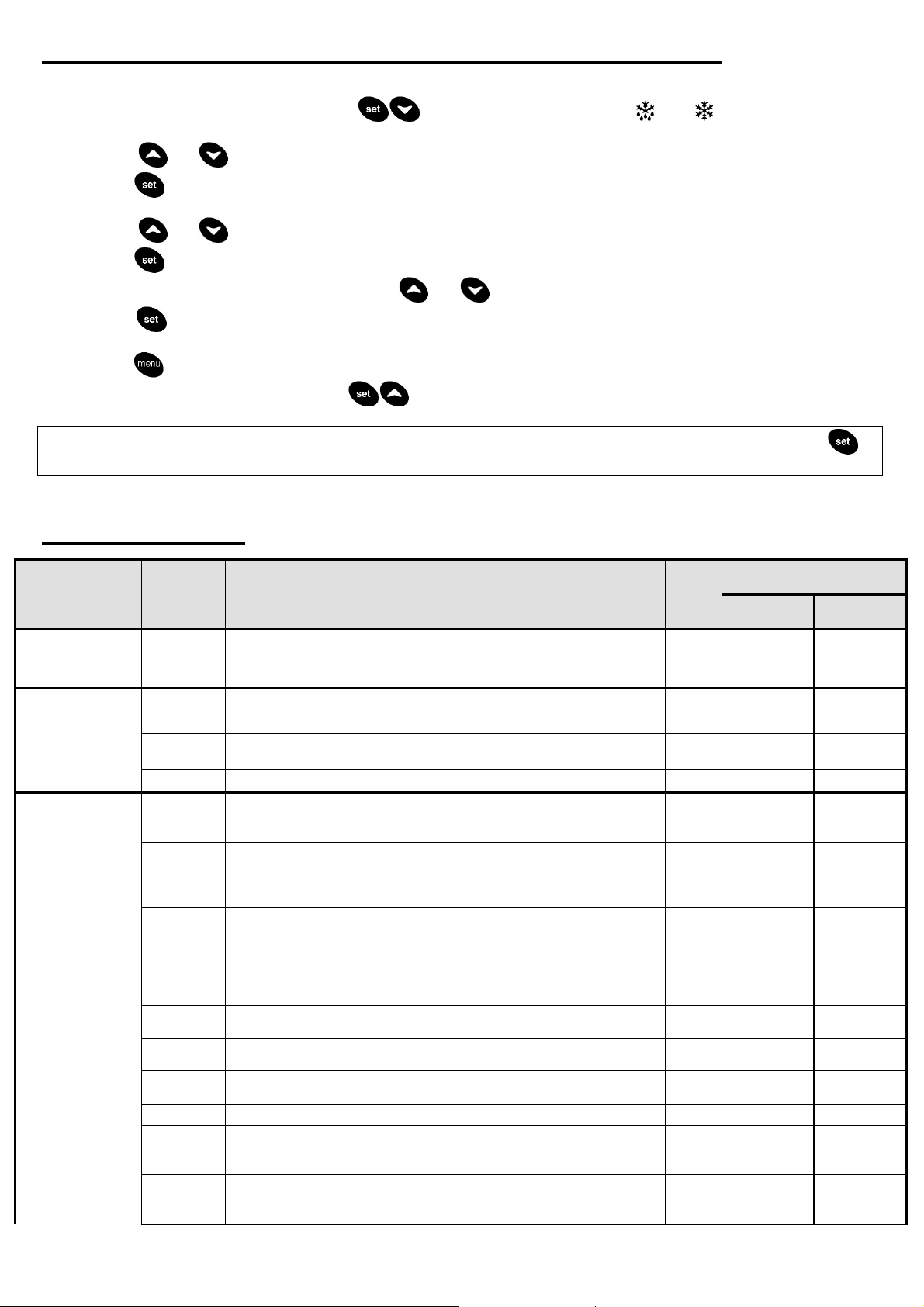
6.6.1 Enter the PARAMETERS MENU and modification of the operation parameters
To ENTER the “parameters menu” proceed as follows:
1. Push simultaneously for a few seconds buttons. The Leds marked with and start to blink, the upper
display will show the label of the first parameters family that can be entered.
2. Using and buttons it’s possible to scroll the available parameters family list.
3. Push button to show the parameters list contained in the selected family: lower display will show alternately the selected
family label and the code of the first parameter contained, while upper display shows the value of the same parameter.
4. Using and buttons it’s possible to scroll through the parameters contained into the selected family.
5. Push to activate the MODIFICATION of the displayed parameter value.
6. Increase or decrease the parameter value using and buttons.
7. Push button to save the new value. In the end of the memorize procedure the controller automatically skips on the
parameters list showing the code of the next parameter.
8. Push button to return at previous menu.
9. To QUIT the menu push simultaneously buttons or wait 4 minutes without pushing any button (Automatic quit).
NOTE: a new set value is memorized also when the outlet is automatic and happens without pushing the confirmation
button.
The CF parameter family can be modified only with the unit in stand-by mode (display shows OFF)
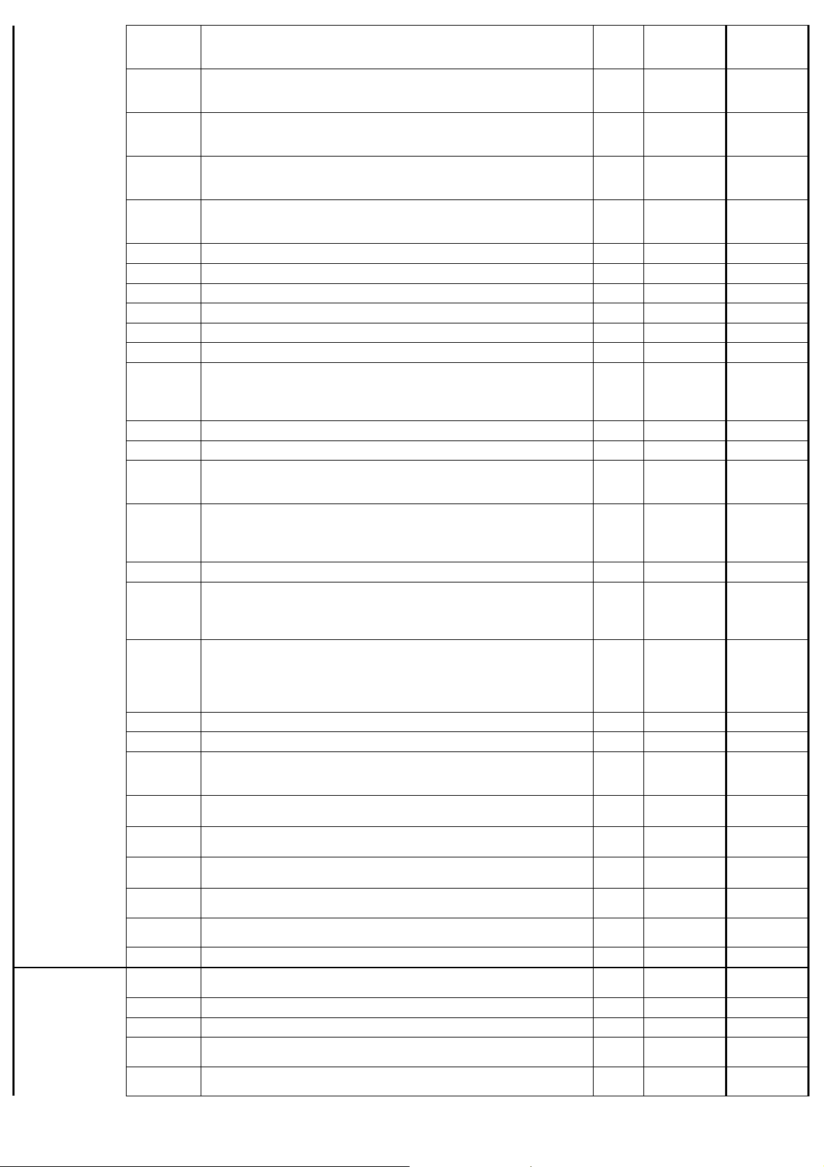
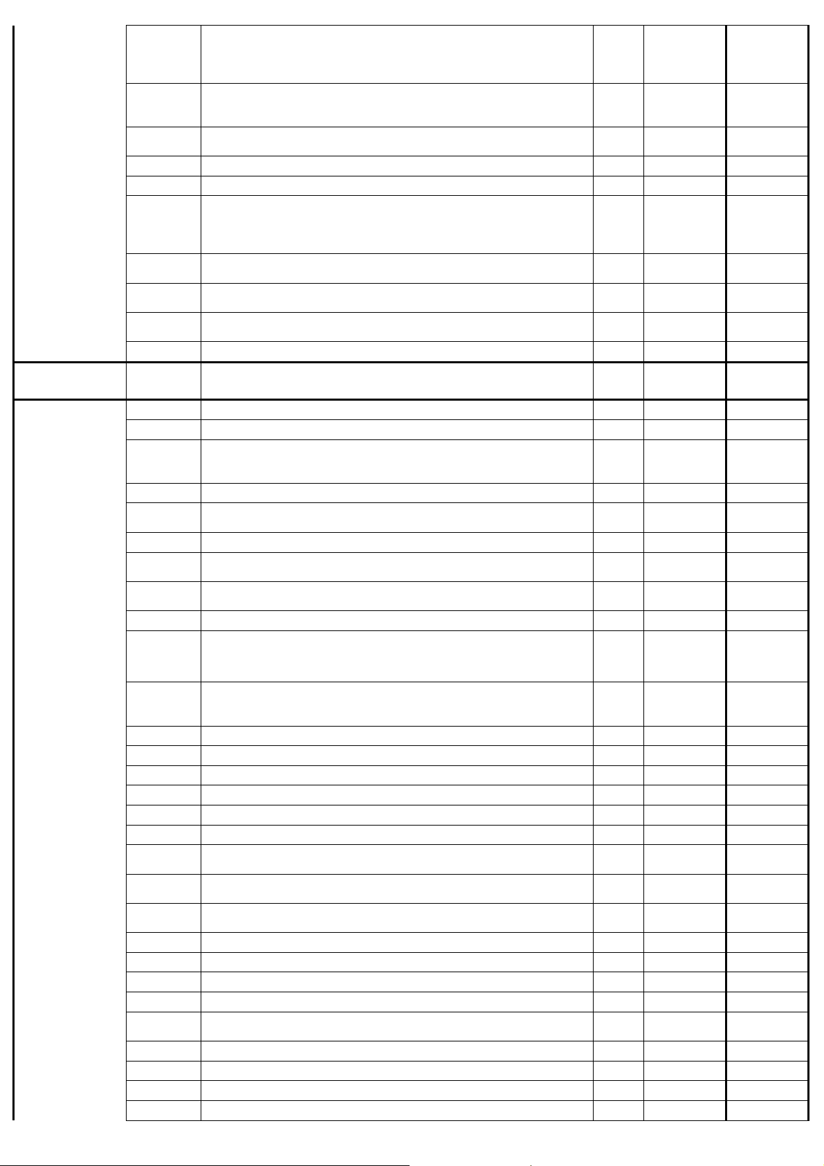
6.6.2 Family Label table
LABEL
Shows all
parameters
Thermoregulatio
n parameters
CF
Contained
Parameter
s
ALL
ST01
ST02
ST05
ST06
CF04
CF05
CF06
CF07
CF08
CF09
CF10
CF11
CF12
CF13
Parameters Description udm
Summer Set Point °C/°F
Summer differential °C/°F
Minimum summer set point °C/°F
Maximum summer set point °C/°F
PB1 probe configuration (DEW POINT)
0 = Probe absent
1 = NTC temperature
PB2 probe configuration (AIR INLET / COMPRESSOR OIL PROBE)
0 = Probe absent
1 = NTC air inlet temperature
2 = NTC temperature for compressor oil
PB3 probe configuration (AMBIENT)
0 = Probe absent
5 = NTC temperature
PB4 probe configuration (REFRIGERANT CIRCUIT SUCTION)
0 = Probe absent
1 = NTC temperature
ID1 digital input configuration (1S2)
0 = refrigerant circuit thermal protection
ID2 digital input configuration (REMOTE ON/OFF)
3 = remote on/off
ID5 digital input CONFIGURATION (1Q2 – FAN THERMAL PROT.)
1 = Fan thermal protection
N.U:
ID1-MF digital input polarity (1S2)
0 = active with close contact
1 = active with open contact
ID2-MF digital input polarity (REMOTE ON/OFF)
0 = active with close contact
1 = active with open contact
Value
150÷225
270÷1360
-5,0 -1,5
1 1
2 2
5 5
1 1
0 0
3 3
1 1
1 1
1 1
DMN FST Kaeltetrockner DFLO150-1360 (Rev-06) –EN-20121100
10
Page 12
Configuration
0,0 0,0
30,0
30,0
-
1,0 -
1,0
0,0 0,0
0,0 0,0
0,0 0,0
3 3
60 60
CF
1 1
4.2 4.2
1 1
18 18
2 2
Parameters
Configuration
Parameters
CO
CF14
CF15
CF16
CF19
CF20
CF22
CF23
CF24
CF25
CF26
CF27
CF28
CF29
CF30
CF32
CF33
CF34
CF35
CF36
CF37
CF38
CF39
CF40
CF41
CF42
CF43
CF44
Pr2
CO01
CO02
CO05
CO06
CO07
ID3 digital input polarity (1P1)
0 = active with close contact
1 = active with open contact
ID4 digital input polarity (1P3)
0 = active with close contact
1 = active with open contact
ID5 digital input polarity (1Q2 – FAN THERMAL PROTECTION)
0 = active with close contact
1 = active with open contact
PB4 polarity (REFRIGERANT CIRCUIT SUCTION)
0 = active with close contact
1 = active with open contact
Condensate drain valve/s relais polarity(RL4)
0 = active with close contact
1 = active with open contact
Refrigerant pressure value = 4ma bar
Refrigerant pressure value = 20ma bar
PB1 probe calibration offset (DEW POINT) °C/°F
PB2 probe calibration offset (AIR INLET / COMPRESSOR OIL) °C/°F
PB3 probe calibration offset (AMBIENT) °C/°F
PB4 probe calibration offset (REFRIGERANT CIRCUIT SUCTION) °C/°F
Condensate drain unit operation
0 = Always ON
1 = Timed
2=Controlled
Condensate drain ON - time Sec
Condensate drain OFF - time Sec
Selection: °C or °F
0 = °C / BAR
1 = °F / psi
Selection of mains frequency
0 = 50 Hz
1 = 60 Hz
2 = Direct current
Serial address
Remote controller
0 = 4 buttons
1 = 6 buttons
2 = 6 buttons with NTC probe on board
Default controller display
0 = IN / PROBE
1 = OUT / PROBE
2 = IN / rtC
3 = OUT / rtc
Firmware release
EEprom parameters map
ID4 digital input CONFIGURATION (LP)
0= low pressure switch (not used)
1= drain discharge control
Delay condensate drain ON from drain control ON
Valid only on CF39=1
Dalay condensate drain OFF from drain control OFF
Valid only on CF39=1
Max time of drain control ON
Valid only on CF39=1
Pump configuration (Pump)
1= pump down valve
Pump configuration (Pump)
1= circulator pump
Password
Minimum delay at compressor re-start
Minimum delay for compressor stop sec10x
Delay at Refrigerant Compressor start form Power ON min10x
Delay compressor start from pump start
Valid only on CO11=2
Delay compressor stop from pump stop
Valid only on CO11=2
min
s
min
sec
10x
s
s
1 1
0 0
1 (0
if water
cooled)
1 1
0 0
2 1
0 0
2 2
1 1
0 0
1 0
1 0
0 0
7 0
1 1
1 1
18 18
1 1
5 5
1 (0
cooled)
if water
DMN FST Kaeltetrockner DFLO150-1360 (Rev-06) –EN-20121100
11
Page 13
Refrigerant
0 0
5,0 5,0
FA
5 5
5 5
1 1
0 0
15 15
AL
5 5
-
1,0 -
1,0
3,0 3,0
10 10
15,0
15,0
2,0 2,0
20 20
60,0
45,0
5,0 5,0
5 5
5 5
5 5
5 5
2 2
compressor
parameters
Pump control
CO11
CO12
CO14
CO16
CO17
CO18
CO19
CO20
CO21
Pr2
0= No pump
1= Pump always ON
2= Starting pump depends on request
Refrigerant Compressor 1
0 = ON
1 = OFF
Refrigerant Compressor hour counter SET (SUGGESTED
MAINTENANCE)
Pump hour counter SET (SUGGESTED MAITENANCE) h 10x
Difference between oil compressor and ambient temperature °C/°F
Pump Down control
0= No pump down control
1= pump down using low pressure switch
2= timed pump down
Max. pump down time in starting and stopping the compressor
Valid only on CO18=1
Pump down time in starting compressor
Valid only on CO18=2
Pump down time in stopping compressor
Valid only on CO18=2
Password
h 10x
s
s
s
0 0
0 0
0 0
0 (2
for
DFLO880
and above)
10 10
20 20
5 5
0 (2
for
DFLO880
and above)
N.U.
Alarm
parameters
---
AL01
AL02
AL03
AL08
AL09
AL10
AL11
AL12
AL13
AL17
AL18
AL19
AL20
AL21
AL22
AL23
AL24
AL25
AL26
AL27
AL28
AL29
AL30
AL31
AL32
AL33
AL34
AL35
AL36
---
Digital input low pressure alarm delay Sec
Low pressure digital input Max. number of activations / hour
Low pressure alarm with dryer in remote OFF status or stand-by
0 = alarm detection OFF
1 = alarm detection ON
Refrigerant compressor thermal protection alarm delay at start Sec
Refrig. compressor thermal protection Max. number of activations /
hour
Refrigerant compressor thermal protection alarm rest after AL09
High temperature alarm Set point PB3 (AMBIENT)
High temperature Differential PB3 (AMBIENT)
High temperature alarm delay PB3 (AMBIENT) Min
Active output contact for remote output relay
0= alarm output ON
1= alarm output OFF
Alarm relay polarity
0= active output close contact
1= active output open contact
Low temperature alarm delay PB1 (DEW POINT) Min
Low temperature alarm Set PB1 (DEW POINT) °C/°F
Low temperature alarm differential PB1 (DEW POINT) °C/°F
High temperature alarm delay PB1 (DEW POINT) Min
High temperature alarm Set point PB1 (DEW POINT) °C/°F
High temperature alarm differential PB1 (DEW POINT) °C/°F
High temperature alarm delay PB2 (AIR INLET)
Valid only if CF05 =1
High temperature alarm Set point PB2 (AIR INLET)
Valid only if CF05 =1
High temperature alarm differential PB2 (AIR INLET)
Valid only if CF05 =1
High temperature alarm delay PB4 (REFRIGERANT SUCTION) Min
High temperature alarm Set point PB4 (REFRIGERANT SUCTION) °C/°F
High temperature alarm differential PB4 (REFRIGERANT SUCTION) °C/°F
Alarm Probe PB1 - Max. number of activations / hour
Alarm Probe PB2 - Max. number of activations / hour (AIR INLET).
Valid only if CF05 =1
Alarm Probe PB3 - Max. number of activations / hour
Alarm Probe PB4 - Max. number of activations / hour
Generic user alarm - Max. number of activations / hour
Delay temperature alarm signalling from compressor start Min
°C/°F
bar/psi
°C/°F
bar/psi
Min
°C/°F
°C/°F
1 1
16 16
46,0 46,0
5,0 5,0
0 0
0 0
20 20
60,0 60,0
10,0 10,0
5 5
DMN FST Kaeltetrockner DFLO150-1360 (Rev-06) –EN-20121100
12
Page 14
-
40,0
-40,0
8,0 8,0
1 1
AL37
AL38
AL39
AL40
AL41
Pr2
Low temperature PB4 PCD alarm (REFRIGERANT SUCTION) °C/°F
Low temperature alarm differential PB4 (REFRIGERANT SUCTION) °C/°F
Low temperature PB4 (REFRIGERANT SUCTION) delay s
Delay low pressure alarm with pump down enable
0= no alarm
Forcing drain to control mode
0= Forcing to drain control
Password
Min
0 0
0 0
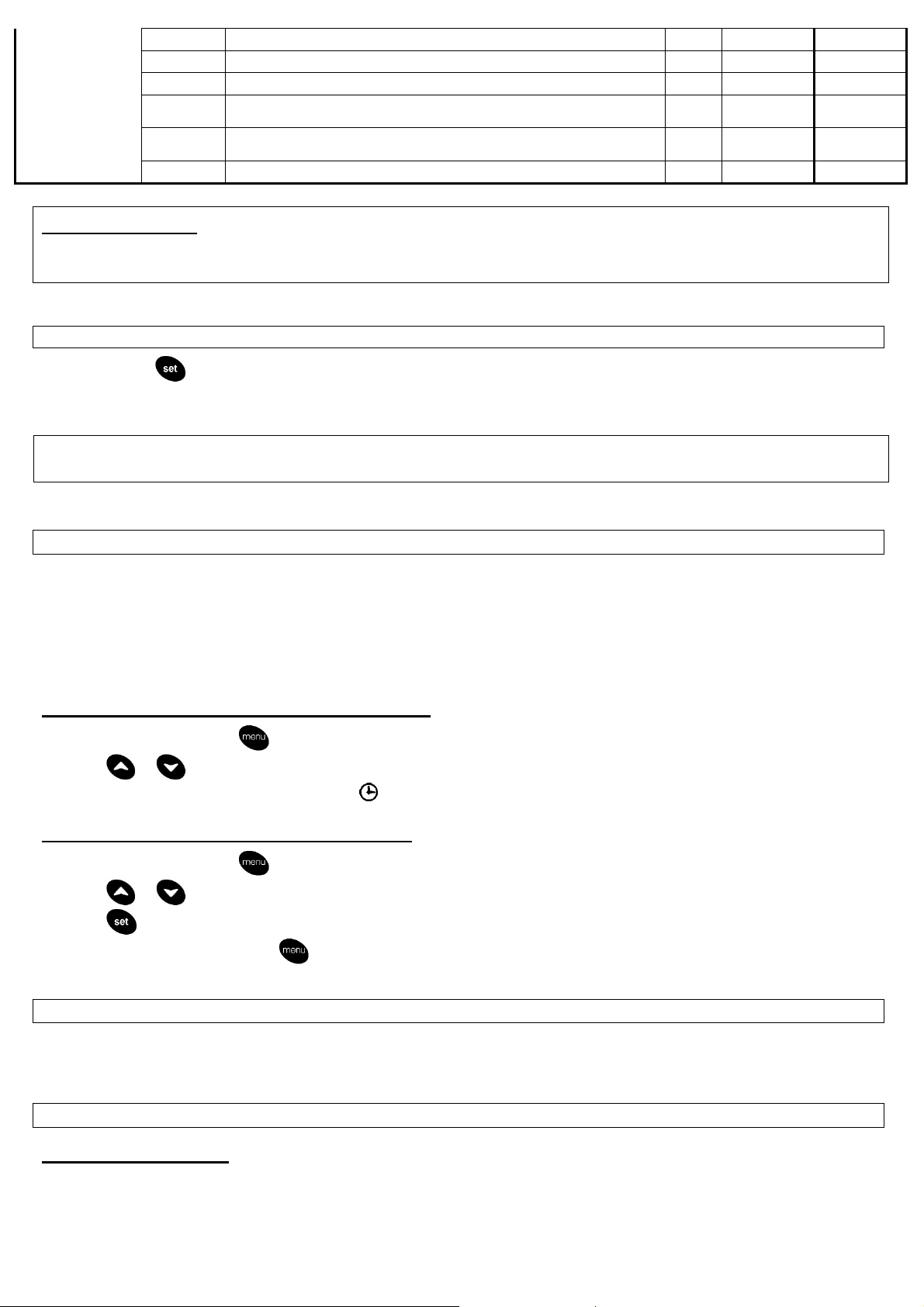
Warning for user:
It’s forbidden to modify setting parameters of the electronic controller without the
authorization of the manufacturer.
6.7 SET POINT DISPLAY
Push and release button:
• Lower display shows the message “SET”.
• Upper display shows current set point value.
NOTE: Any change to the machine’s configuration parameters could be harmful to its
efficiency and therefore it must be done only in collaboration with the Manufacturer.
6.8 SUGGESTED MAINTENANCE FUNCTION
The electronic controller can be set through the parameters:
• CO14 (Refrigerant Compressor hour counter SET) to advise the operator that preventive maintenance of the dryer is required
(according to CAP. 5.0, alarm code AMnC).
This alarm WILL NOT STOP THE AIR DRYER WORKING. The alarm disappears after resetting the hour counter from the Functions
Menu.
Display Refrigerant Compressor working hours
1) Enter the Functions Menu ( button).
2) Push or buttons until the lower display will show the label “C1Hr” (refrigerant compressor working hours). Upper display
shows the number of working hours. The icon will be on.
Reset Refrigerant Compressor working hours
1) Enter the Functions Menu ( button).
2) Push or buttons until the lower display will show the label “C1Hr”. Upper display shows the number of working hours.
3) Push button for more than 3 sec. so the upper display will show “0” confirming the reset.
4) Quit the Functions menu pushing button or wait 15 sec. (automatic quit).
6.9 BLACK OUT
After a power black-out:
1. The controller restarts from the previous status.
2. All the working time delay will be reloaded.
6.10 REMOTE CONTROLS
6.10.1 Remote ON/OFF
The dryer can be remotely started and stopped (REMOTE ON/OFF). Proceed as follow to activate this function:
1. Disconnect the dryer from electrical supply and open the electrical box.
2. Remove the bridge between the two terminal blocks marked with “ON/OFF” (See electric wiring diagram).
3. Connect the “ON/OFF” terminal blocks to remote a unipolar switch.
DMN FST Kaeltetrockner DFLO150-1360 (Rev-06) –EN-20121100
13
Page 15
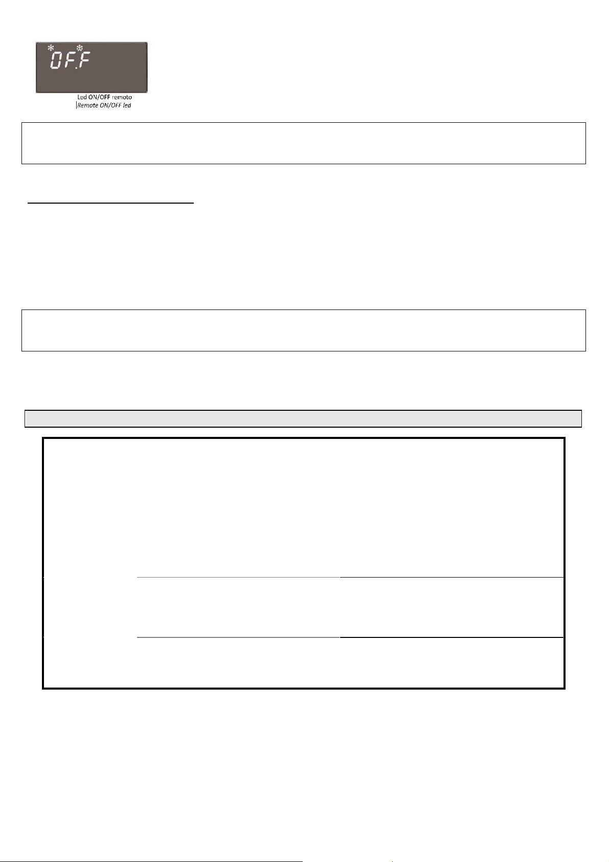
Remote ON/OFF digital input is configured as follow: close contact = dryer ON.
•
•
•
•
•
•
When the dryer is switched off using remote OFF command, the controller shows on upper display line
the message “OFF” and the remote ON/OFF led blinks.
The remote OFF function disables the ON function from the dryer’s control board (until the ON function
is activated from remote ON/OFF switch). To restart the dryer it’s necessary to operate on the remote
control.
The activation of the above function is at the user’s discretion. The user will purchase all necessary
installation materials himself. Any operation which needs access to the dryer must be carried out by
qualified personnel.
6.10.2 Remote signalling alarm
The dryer control board is supplied complete with a digital output configured as remote signalling alarm. This digital output is controlled
by a relays configured as normally open: when an alarm is detected, these relays close a circuit. The status of the relays can be
inverted, if necessary, using AL18 programming parameter (See 6.6.2 Parameters table).
Proceed as follows to activate a remote alarm output:
1. The User must provide a signaller in compliance to output relays electrical features (solenoid coil, light bulb, acoustic signaller,
...).
2. Disconnect the dryer from the electrical supply and open the electrical box.
3. Connect the signaller on “REMOTE ALARM” terminal blocks (See electric wiring diagram).
The activation of the above function is at the user’s discretion. The user will purchase all necessary
installation materials himself. Any operation which needs access to the dryer must be carried out by
qualified personnel.
Alarm Output relays electric features:
Voltage on User’s discretion
max. current 3A
7.0 TROUBLESHOOTING
SYMPTOM
A) Temperature
shown in display
higher than the preset
value.
B) Excessive air
pressure drop across
dryer.
C) Water present in air
downstream of dryer.
POSSIBLE ORIGIN
High compressed air inlet temperature.
• High compressed air flow.
• High ambient temperature.
• Dirty refrigerant condenser.
• Low refrigerant charge.
• Phases connected incorrectly.
• Faulty refrigerant compressor.
• Faulty freon solenoid valve.
• Faulty fan.
• Faulty fan pressure switch or thermostat.
• Faulty electronic controller
Inlet / outlet piping reversed.
• Temperature probe out of well.
• Faulty freon solenoid valve.
• Ambient temperature below freezing.
• Obstruction in air circuit.
• Air by – pass valve close.
Condensate drain strainer fouled.
• Faulty condensate drainer.
• Faulty electronic controller.
• High dew – point temperature.
• Air by – pass valve open.
SOLUTION
Reduce air temperature to within design limits.
• Reduce air flow to within design limits.
• Increase ventilation rate of installation area.
• Clean condenser.
• Locate and repair leak and re-charge.
• Connect the phases correctly.
• Replace item.
• Replace item.
• Replace item.
• Replace item.
• Replace item.
Connect properly.
• Re-install.
• Replace item.
• Install dryer in heated space.
• Locate and remove blockage.
• Open valve.
Clean strainer.
• Replace item.
• Replace item.
• See Symptom #A above.
• Close valve.
DMN FST Kaeltetrockner DFLO150-1360 (Rev-06) –EN-20121100
14
Page 16
Pic.2
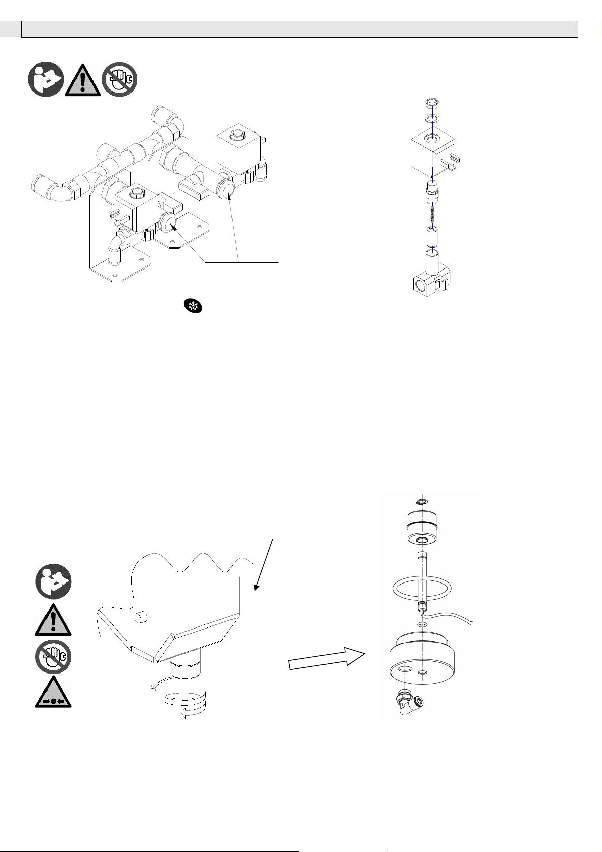
8.0 CONDENSATE DRAIN
8.1 Drain valve maintenance
(F)
• Close the ball valve located on the filter/stop installed at the drain trap inlet.
• Depressurize the trap by pushing the button on the control panel.
• Unscrew the plug in the end of the filter/stop to access the filter screen (F) and
clean it with a compressed air jet.
• Reassemble and open filter/stop valve.
Cleaning of the drain solenoid valve
8.2 INTEGRATED NO LOSS DRAIN
Level sensor (Reed) for integrated No loss drain
The level sensor allows the electronic controller to activate the solenoid valve only if need, without compressed air loss,
measuring the condensate level into the separator tank.
If the float remains blocked in its open position, causing loss of compressed air, the electronic controller switches to timed
mode until the level sensor restores the normal operation.
Cleaning of the level sensor.
Heat exchanger
DMN FST Kaeltetrockner DFLO150-1360 (Rev-06) –EN-20121100
15
Page 17
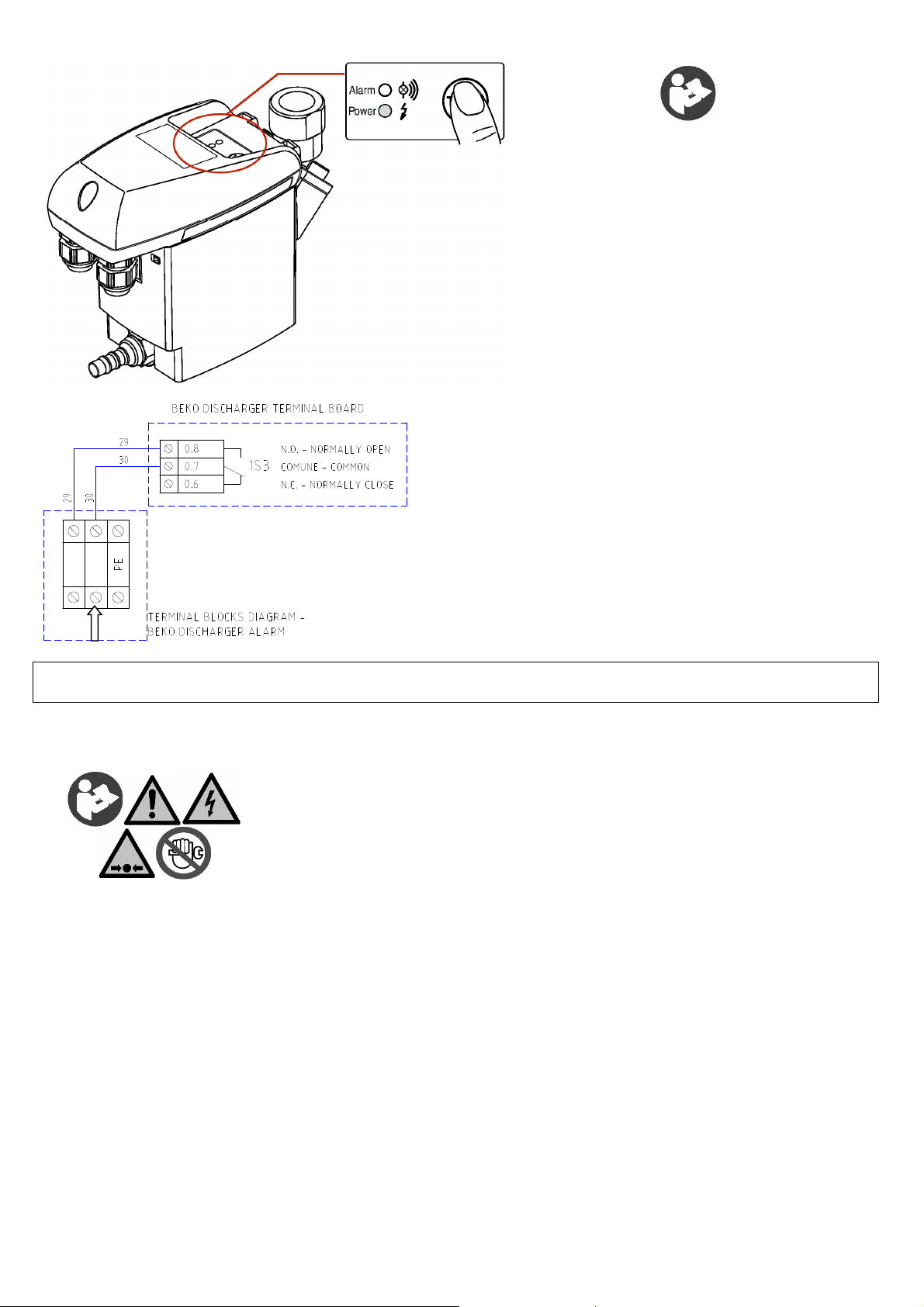
8.3 NO LOSS CONDENSATE DRAIN
The electronic drain discharge is supplied completely with an output
Electronic drain discharge is the new discharger applicable to any
compressed air systems. It eliminates the condensate without
wasting compressed air.
Electronic drain discharge starts automatically, without the need
of any adjustment. The condensate discharge occurs to the use of
an electronic sensor, which detects the amount of condensate in
the integrated water collecting tank. The level sensor drives start
and duration of the drainage, so preventing any wasting of
compressed air.
At the end of installation, put the system under pressure and push
the TEST key repeatedly to eliminate the air bubbles contained in
the discharger inlet fittings.
Please refer to the attached CD of the discharger for complete
instructions.
To this discharger will be applied the Beko warranty conditions.
configured as remote signalling alarm.
Proceed as follows to activate a remote alarm output:
1.The User must provide a signaller in compliance to output relay
electrical features (solenoid coil, light bulb, acoustic signaller, ...).
2. Disconnect the dryer from electrical feeding and open the electrical
box.
3. Connect the signaller on “BEKO DISCHARGER ALARM” terminal
blocks (See electric wiring diagram).
Alarm Output relays electric features:
Voltage <250Vac
max. current <1,0A
Activation of the above function is on User’s discretion. The User will purchase all necessary installation
material by himself. Any operation which needs access to the dryer must be carried out by qualified personnel.
8.4 Maintenance and malfunctioning treatment
Should the discharger not operate correctly, try to act on the TEST key to clean the mesh
filter.
Never remove the discharger body. Should the malfunctioning persist, contact our Customer
Service.
Before carrying out any work on the electrical parts, make sure that the main switch interrupts
the electricity supply to the dryer and then affix appropriate warning signs to avoid the
machine being reconnected to the electricity mains!
DMN FST Kaeltetrockner DFLO150-1360 (Rev-06) –EN-20121100
16
Page 18
9.0 DECOMMISSIONING
All work on the dryer may only be carried out by specialist personnel!
Follow this procedure if you need to shut down the dryer:
• Stop the device and permanently isolate it from the electricity mains;
• Disconnect the power cable;
• Take pressure off the air circuit;
• Empty the tank and the internal cooling medium circuits;
• If the device has to be dispatched, use the original or similar packaging and keep the device in an up-right position.
Before carrying out any work on the electrical parts, make sure that the main switch interrupts the electricity supply to the
dryer and then affix appropriate warning signs to avoid the machine being reconnected to the electricity mains!
Please consult the contents and the safety instructions in the relevant sections of these instructions for details of the correct
handling and storage of the chiller. Remove any residual cooling medium from the dryer in a manner appropriate to its
properties and in accordance with the legislation in force.
If the device has to be demolished: Never open the sealed cooling assembly (compressor, evaporator and condenser) if
there may be any refrigerant or lubricating oil present!
Send the chiller to an approved waste disposal company in accordance with current environmental protection legislation. The
other materials/waste constituents must be treated in line with the provisions of the valid legislation.
10.0 SAFETY REQUIREMENTS
In case of Freon gas leak, it’s important to keep in mind the following risks / damages to goods and people.
FREON DANGERS FIRST AID
R134a
R404a
R407C
R507
High concentration can cause asphyxia , lose of consciousness and lose of
mobility.
Low concentration can cause narcotic effects
Contact with skin and eyes.
Swallowing is an improbable cause of risk.
Move the victim to an uncontaminated zone,
keep him/her warm and call the doctor.
Rinse immediately the eyes with water for 15
minutes.
In case of low temperature Freon gas spray
burn sprinkle water for 15 minutes.
11.0 DAILY REGISTER
According to EN 378-1 specification, it’s necessary to keep an updated daily register of the refrigerant system.
The register, freely chosen and filled in by the dryer’s user, must contain the following information:
• All repairing and maintenance interventions;
• Freon consumption (new, re-utilized, recycled) and Freon quantities loaded for each maintenance intervention;
• Test results on Freon gas;
• Freon origin;
• Modifications and replacements of system components.
• Periodical tests results;
• Significant working periods.
Keep the register in the engine room and/or in other rooms, just to have it put in an accessible place to the person in charge of its maintenance.
DMN FST Kaeltetrockner DFLO150-1360 (Rev-06) –EN-20121100
17
Page 19
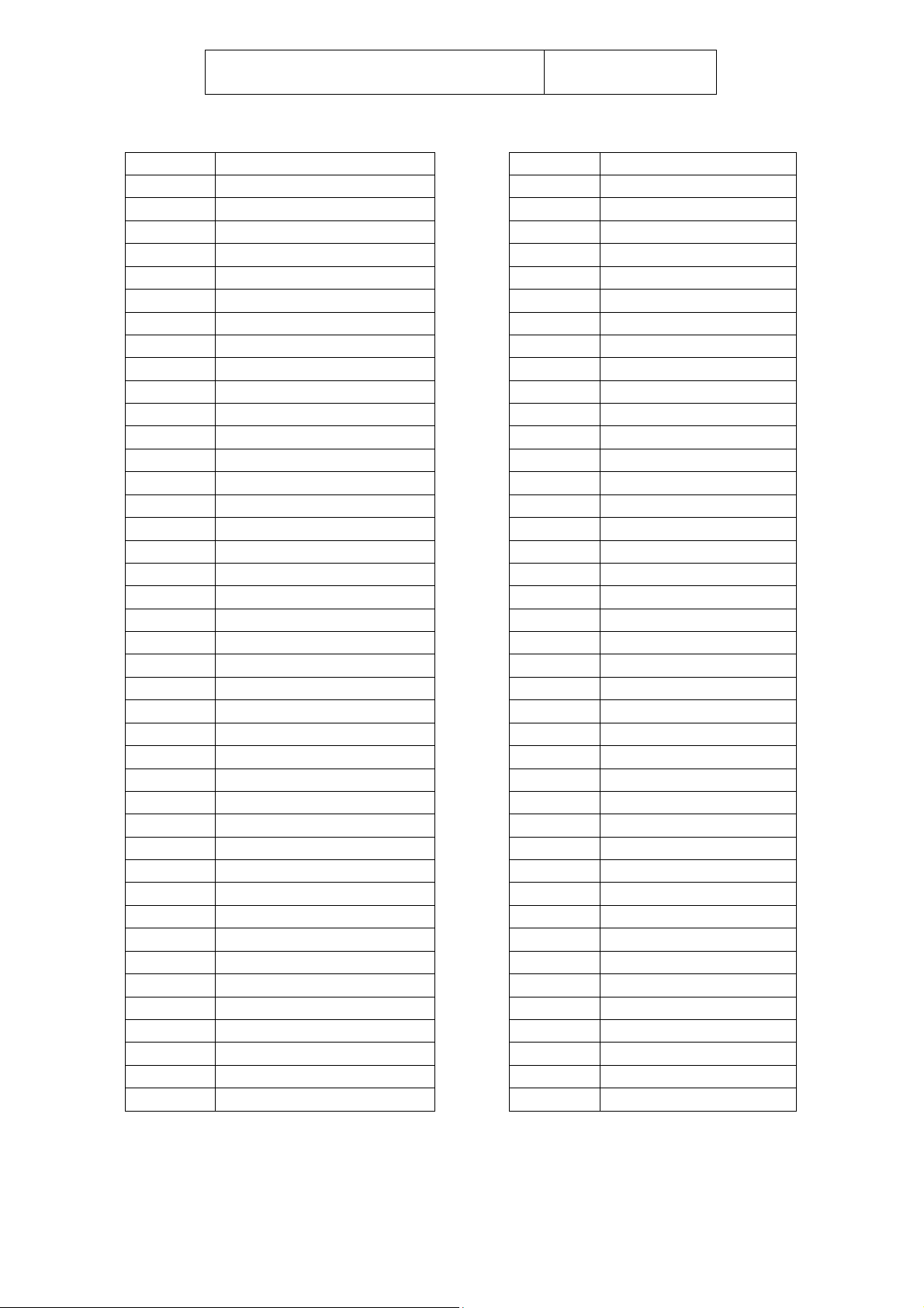
ATTACHMENTS TO THE MANUAL
1A1
1B1
1B2
1B3
1M1
1M2
1M3
1P1
1P2
1Q1
1Q2
1Q3
1R1
1R2
1R3
1S1
1S2
1T1-1T2-1T3
1V1
1V2
1V3
ACC
CB
CBL
CNA
CND
CNV
CPL
EB
ED
EH
EP
EQ
EVA
F1-F2
FD
FF
FH
FP
FQ
FR
FT
Electronic Controller
Drain solenoid valve coil
Liquid solenoid valve coil
By-pass solenoid valve coil
Refrigerant compressor
Fan Motor
Glycol circulator
High pressure Switch
Fan pressure Switch
Compressor circuit breaker
Fan circuit breaker
Transformer circuit breaker
Compressor crankcase heater
Electrical panel heater
Condensate drain heater
Main power switch
Plug
Transformer
Solenoid drain Valve
Liquid solenoid valve
By-pass solenoid valve
Tank
Compressor box
Cables
Sacrificial anode
Condenser
Fan capacitor
Capillary tube
Electrical box
10 micron filter element
0.01 micron filter element
1 micron filter element
5 micron filter element
Evaporator
Fuses
Air filter 10 micron
Filter dryer
Air filter 0.01 micron
Air filter 1 micron
Air filter 5 micron
Drain screen
Noise filter
FV
G
GFCI
IM
K1
K2
KRC1
MHP
MLP
PCP
PR
R
RB1
RBF
RBS
RD1
REF
RF
RL
RR
RS
PB / RT
SC
SCO
SH
SLI
SSC
STC
TEMP
TH
THR
TLT
VA
VB
VBA
VE
VNR
VP
VS
VSR
VT
X1-X2-X3-X4
Legend
Fan motor fuse
Grid
Ground fault circuit breaker
Moisture indicator
Contactor switch
Fan contactor switch
Protection module
High pressure manometer
Low pressure manometer
Thermal protection
Air-air heat exchanger
Compressor relay
Freon Tap
Tap with strainer
Changeover tap
Reed sensor
Fan speed regulator
Phase control relais
Liquid receiver
Rotalock tap
RS485 Interface
Temperature probes
Heat exchanger base
Condensate separator
Sensor hose
Liquid separator
Condensate drain
Control panel cover
Time setter
Thermostat
Electrical box thermostat
Remote cont. Thermostat
Glycol valve
By-pass hot gas valve
Air by-pass valve
Expansion valve
One way valves with strainer
Pressostatic valve
Tap
Freon safety valve
Fan blade
Terminal blocks
DMN FST Kaeltetrockner DFLO150-1360 (Rev-06) –EN-20121100
18
Page 20
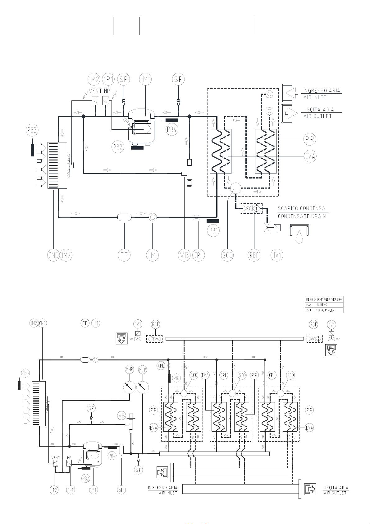
(A)
REFRIGERANT CIRCUIT
DFLO150 – DFLO180 – DFLO225
DFLO270
DMN FST Kaeltetrockner DFLO150-1360 (Rev-06) –EN-20121100
19
Page 21
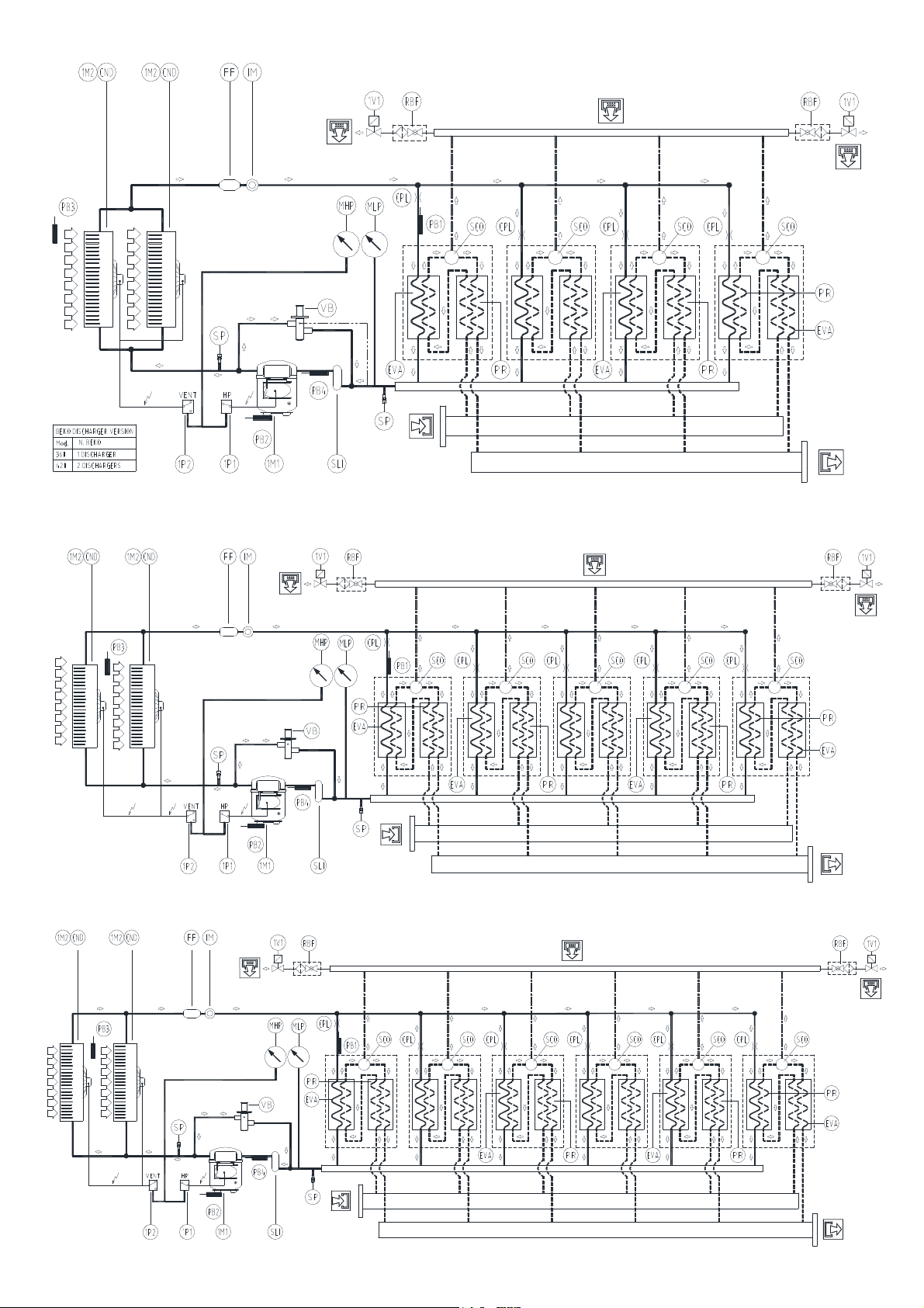
DFLO360 – DFLO420
DFLO530
DFLO600 – DFLO680
DMN FST Kaeltetrockner DFLO150-1360 (Rev-06) –EN-20121100
20
Page 22
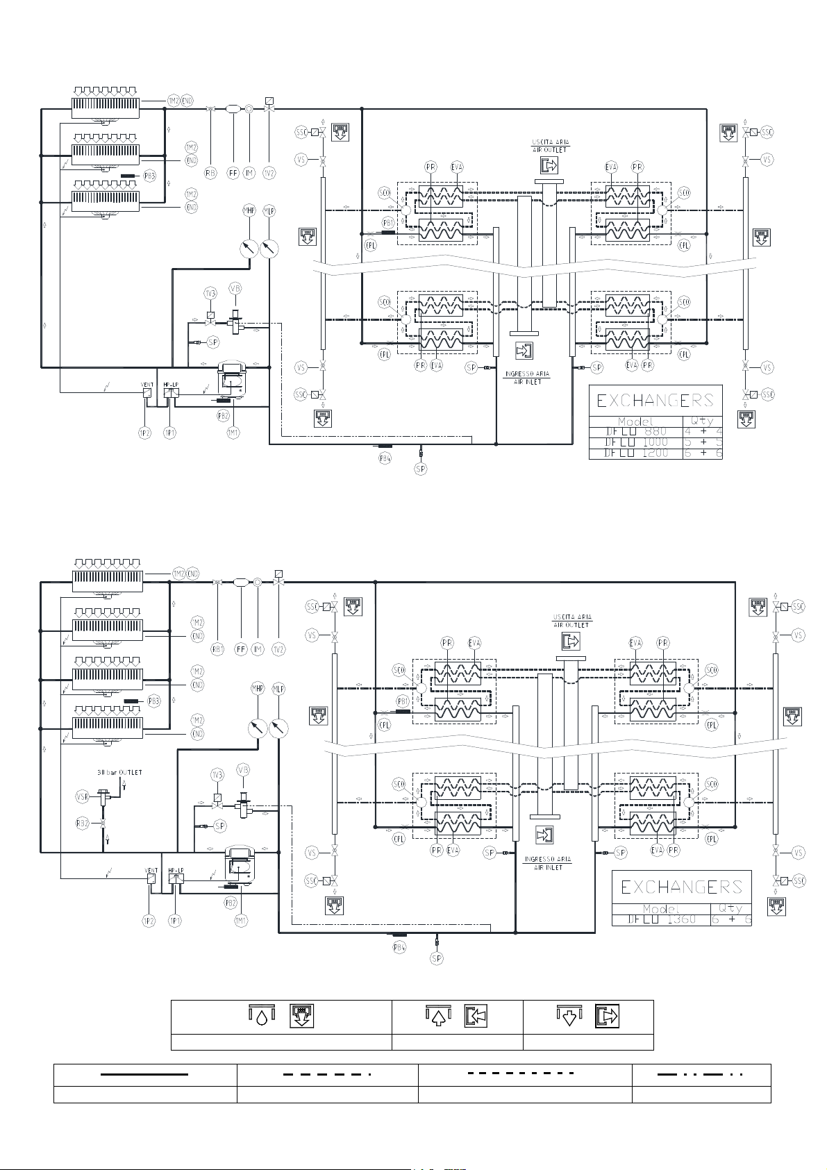
DFLO880 – DFLO1000 – DFLO1200
DFLO1360
/ / /
Refrigerant line Compressed air line Condensate drain line Equalization line
DMN FST Kaeltetrockner DFLO150-1360 (Rev-06) –EN-20121100
Condensate drain Air inlet Air outlet
21
Page 23
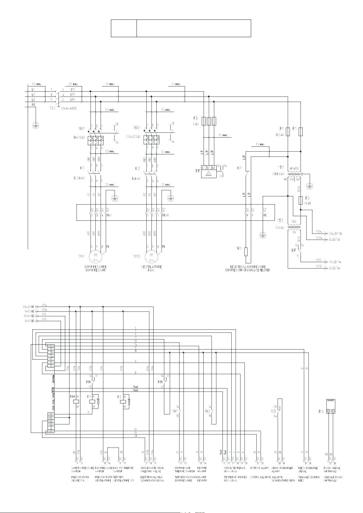
(B)
WIRING DIAGRAM
DFLO150 – DFLO180 – DFLO225
Power Circuit
Control Circuit diagram
DMN FST Kaeltetrockner DFLO150-1360 (Rev-06) –EN-20121100
22
Page 24
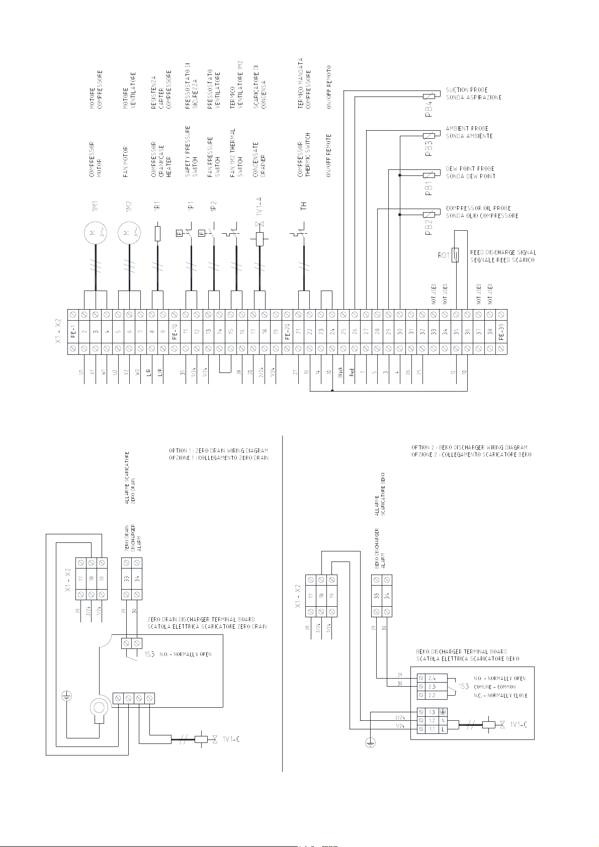
Terminal blocks (Timed drain)
Terminal blocks (Intelli & Beko drain)
DMN FST Kaeltetrockner DFLO150-1360 (Rev-06) –EN-20121100
23
Page 25
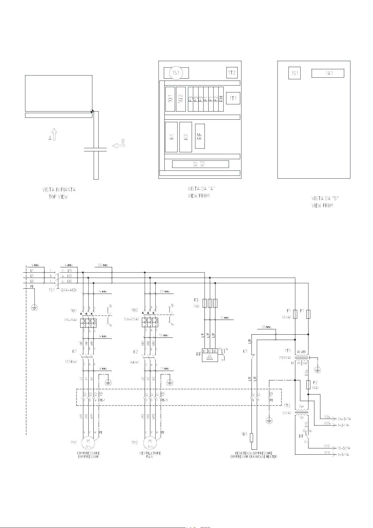
Components layout
DFLO270
Power Circuit
DMN FST Kaeltetrockner DFLO150-1360 (Rev-06) –EN-20121100
24
Page 26
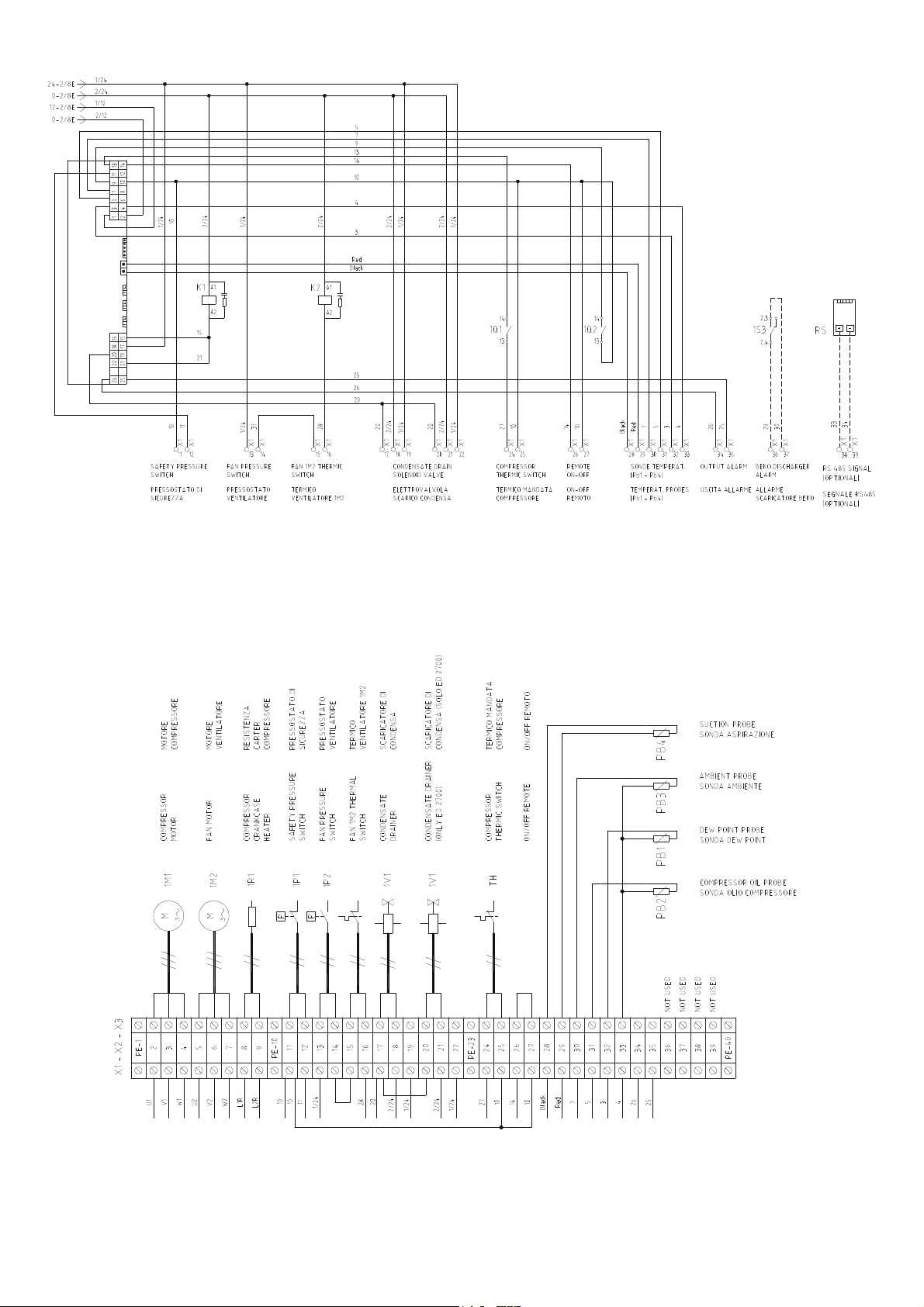
Control Circuit diagram
Terminal blocks (Timed drain)
DMN FST Kaeltetrockner DFLO150-1360 (Rev-06) –EN-20121100
25
Page 27
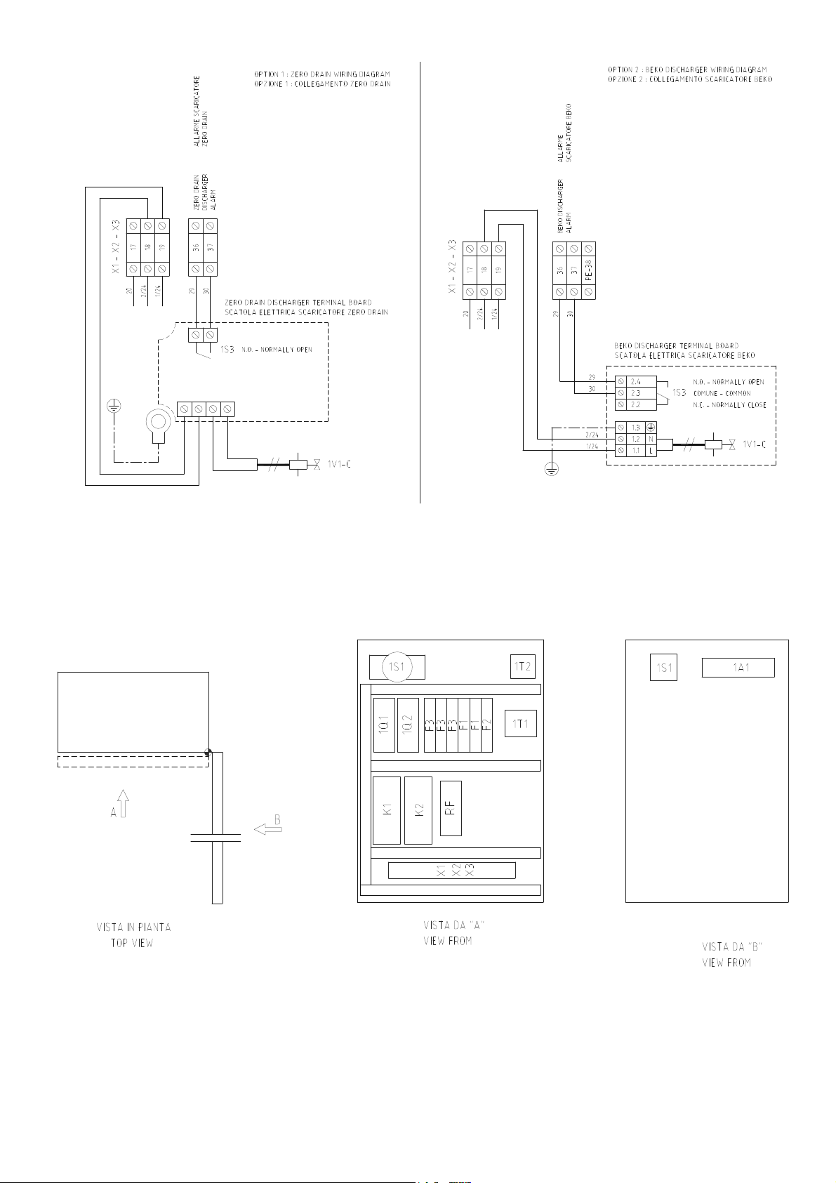
Terminal blocks (Intelli & Beko drain)
Components layout
DMN FST Kaeltetrockner DFLO150-1360 (Rev-06) –EN-20121100
26
Page 28
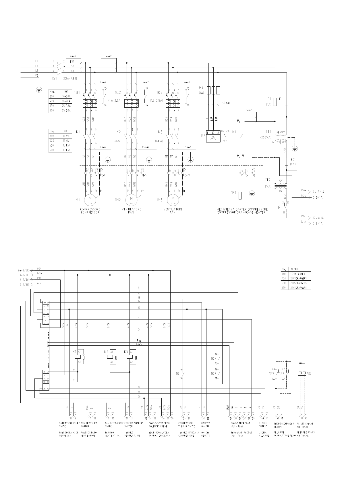
DFLO360 – DFLO420 – DFLO530 – DFLO600
Power Circuit
Control Circuit diagram
DMN FST Kaeltetrockner DFLO150-1360 (Rev-06) –EN-20121100
27
Page 29
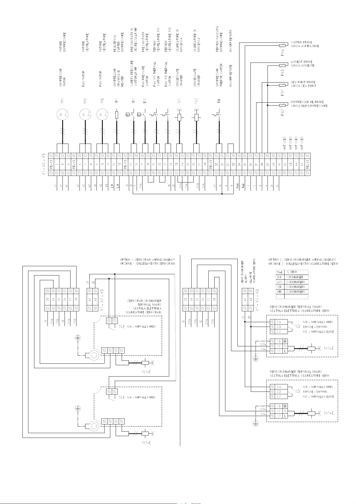
Terminal blocks (Timed version)
Terminal blocks (Intelli & Beko drain)
DMN FST Kaeltetrockner DFLO150-1360 (Rev-06) –EN-20121100
28
Page 30
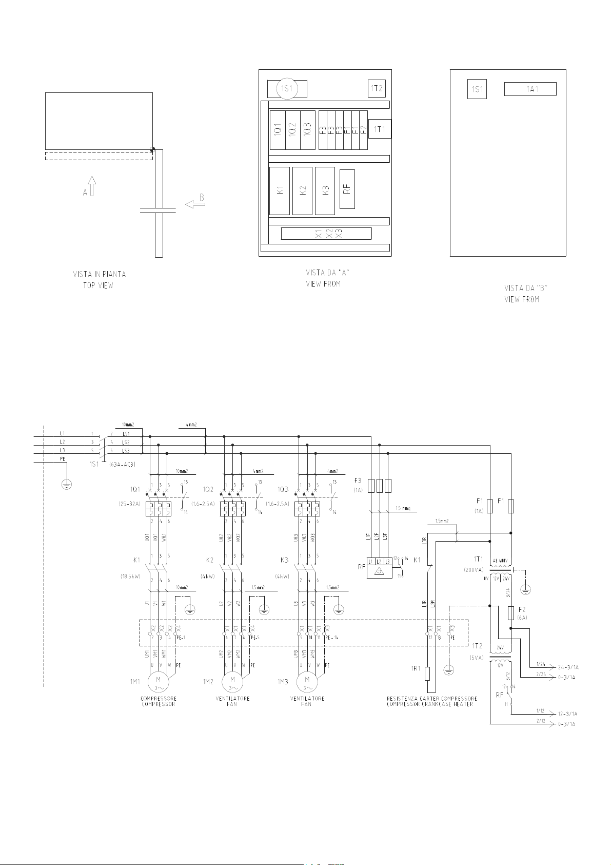
Components layout
DFLO680
Power Circuit
DMN FST Kaeltetrockner DFLO150-1360 (Rev-06) –EN-20121100
29
Page 31
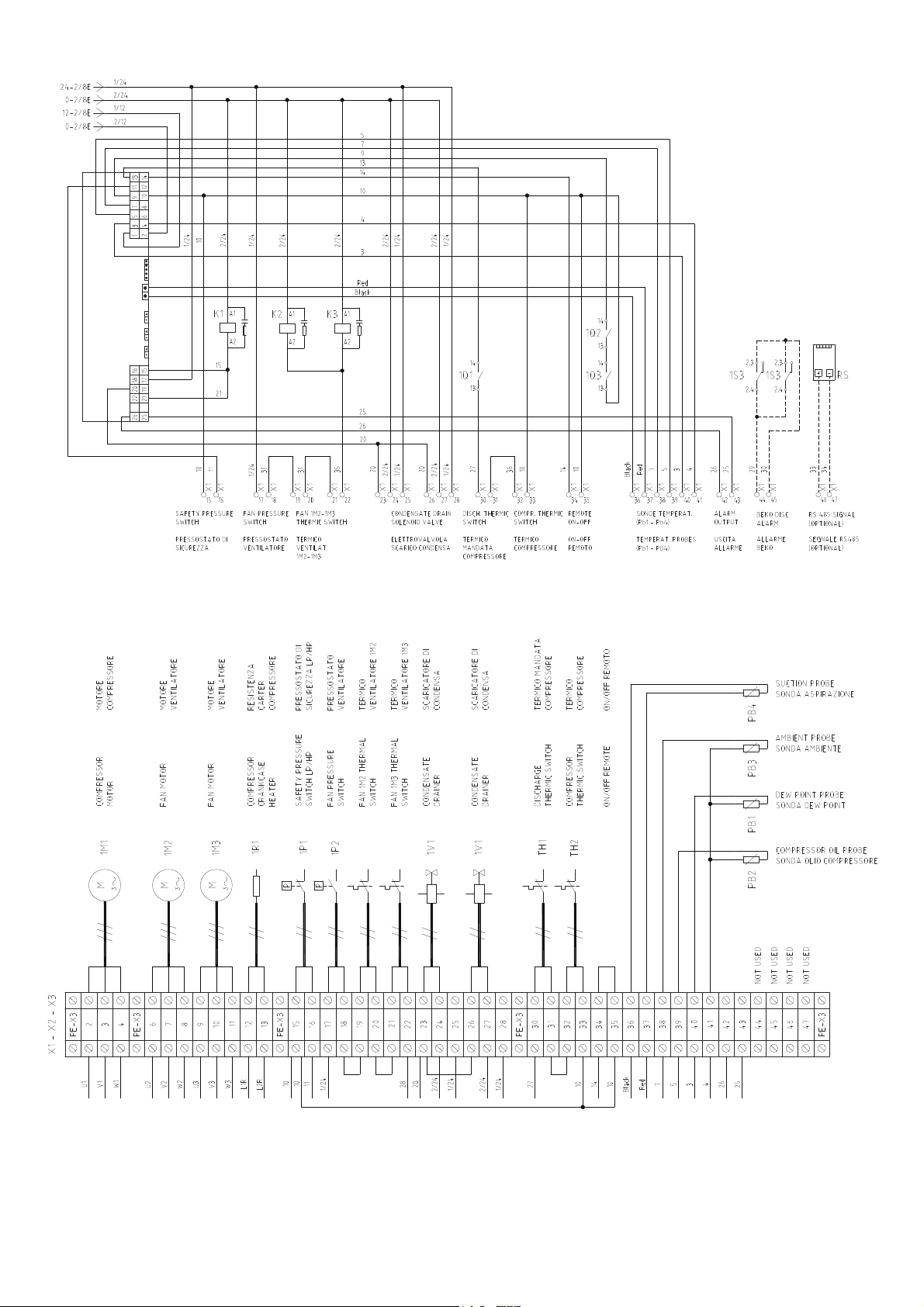
Control Circuit diagram
Terminal blocks (Timed version)
DMN FST Kaeltetrockner DFLO150-1360 (Rev-06) –EN-20121100
30
Page 32
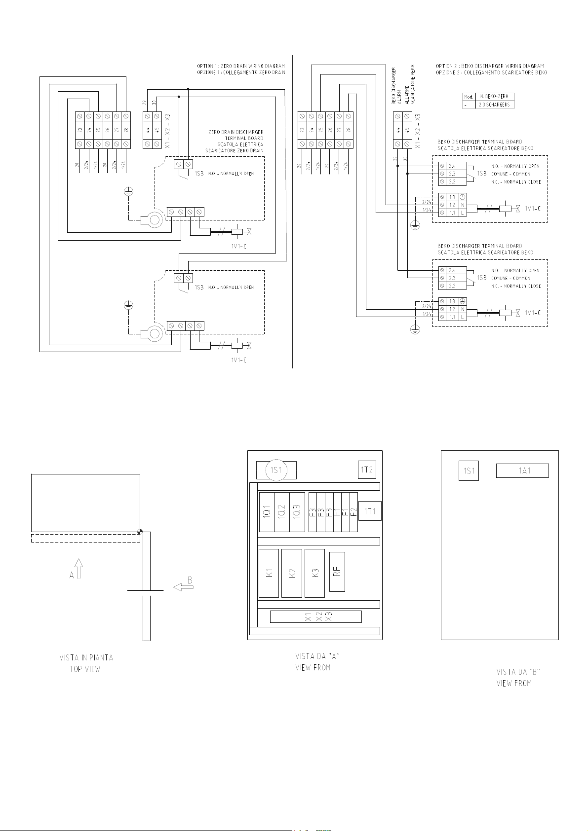
Terminal blocks (Zero Drain & Beko drain)
Components layout
DMN FST Kaeltetrockner DFLO150-1360 (Rev-06) –EN-20121100
31
Page 33
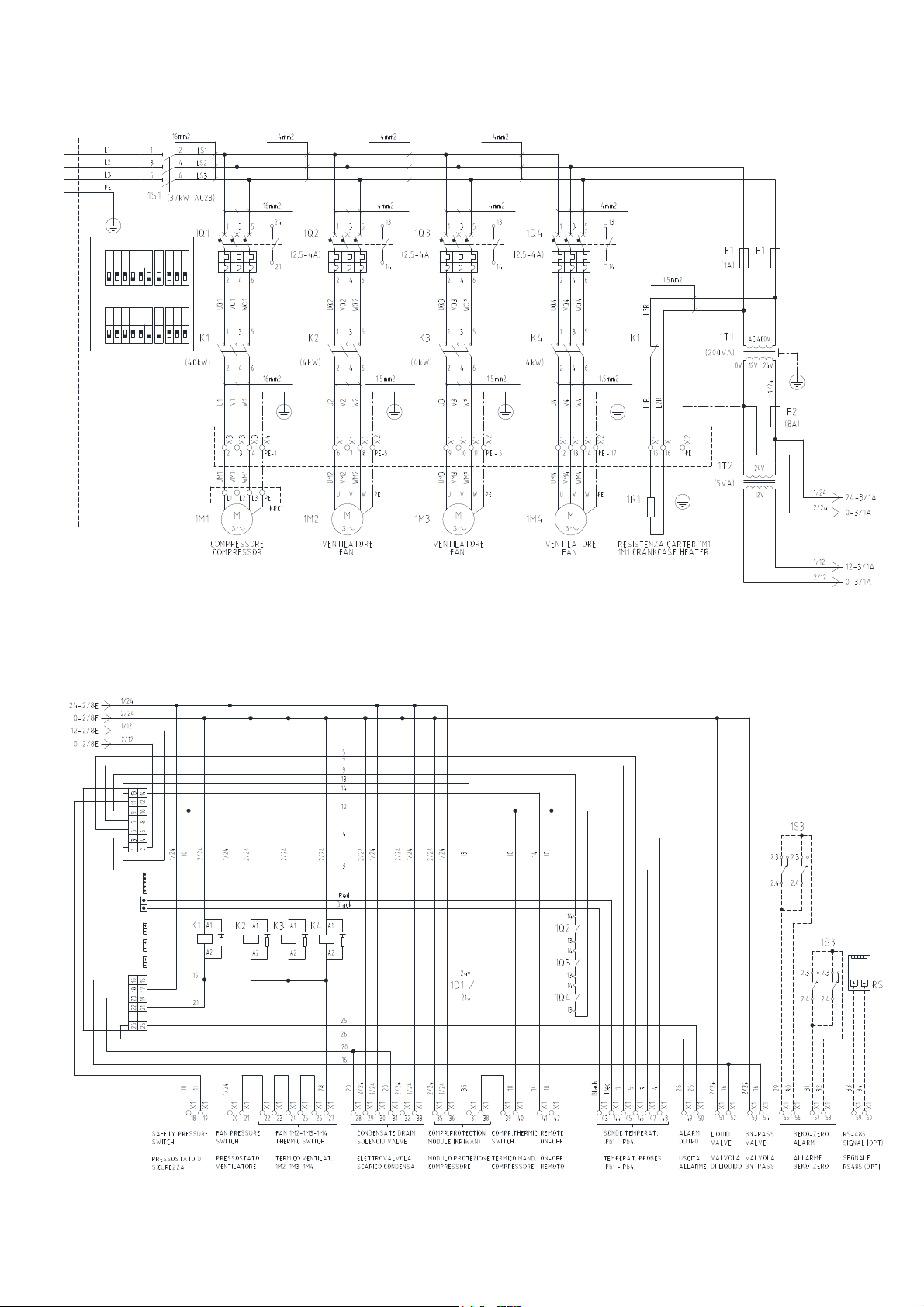
DFLO880 – DFLO1000 – DFLO1200
Power Circuit
OFF
OFF
1Q1 SETTING (38.4)
L
Class
0.32
0.16ON0.08
0.04
1Q1 SETTING (48.0)
L
0.32
0.16ON0.08
0.04
I
4
2
1
U
I
4
2
1
UClass
Control Circuit diagram
DMN FST Kaeltetrockner DFLO150-1360 (Rev-06) –EN-20121100
32
Page 34
Terminal blocks (Timed version)
DMN FST Kaeltetrockner DFLO150-1360 (Rev-06) –EN-20121100
33
Page 35
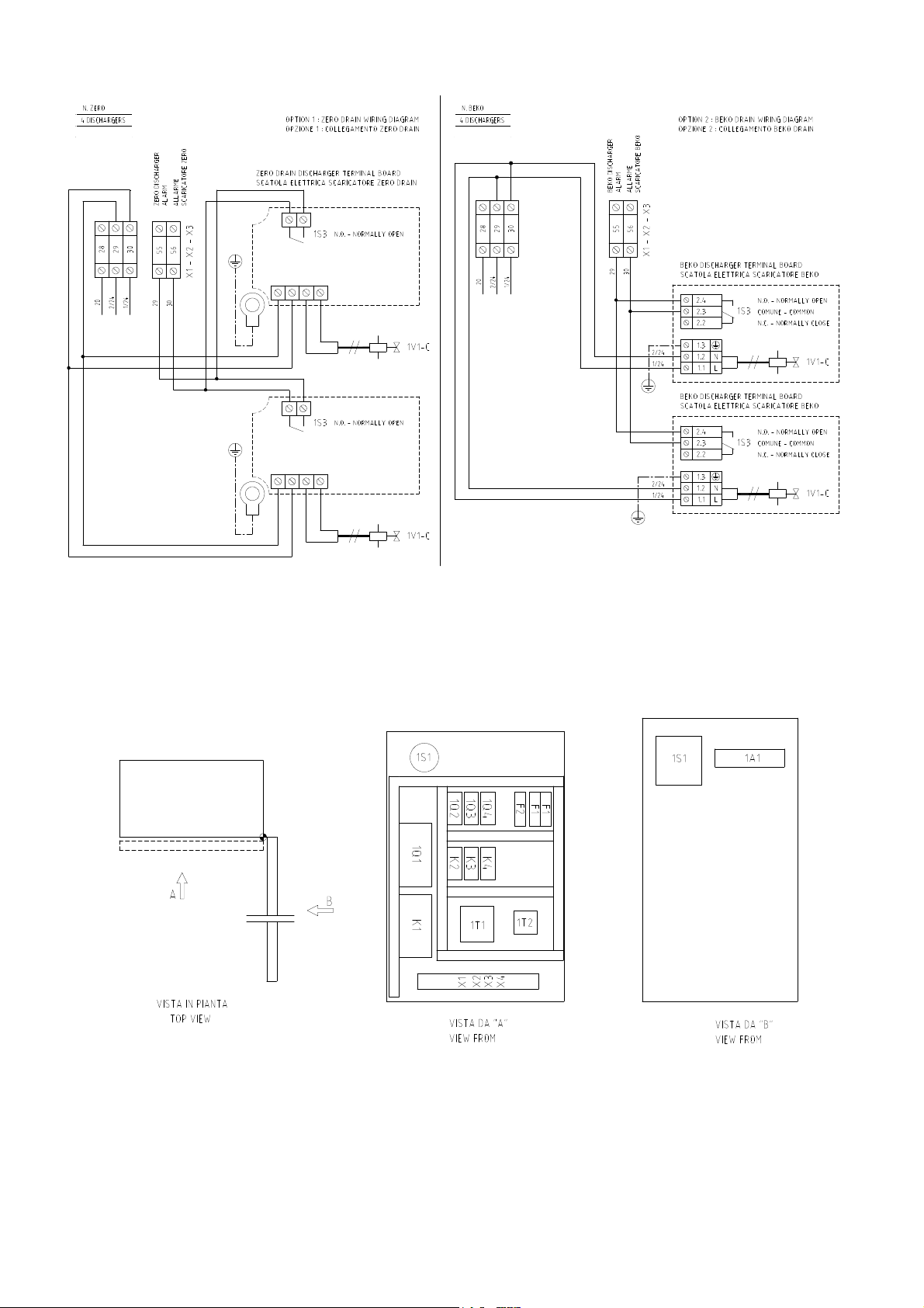
Terminal blocks (Zero Drain & Beko drain)
Components layout
DMN FST Kaeltetrockner DFLO150-1360 (Rev-06) –EN-20121100
34
Page 36
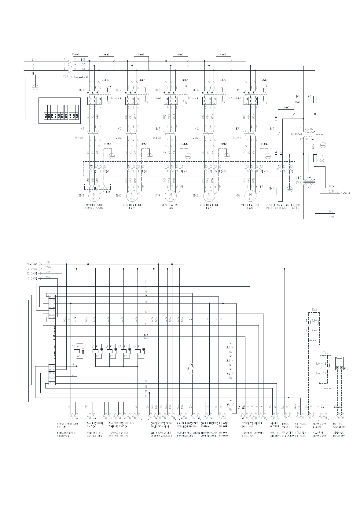
DFLO1360
Power Circuit
OFF
1Q1 SETTING (56.0)
L
0.32
0.16ON0.08
0.04
Class
I
4
2
1
U
Control Circuit diagram
DMN FST Kaeltetrockner DFLO150-1360 (Rev-06) –EN-20121100
35
Page 37
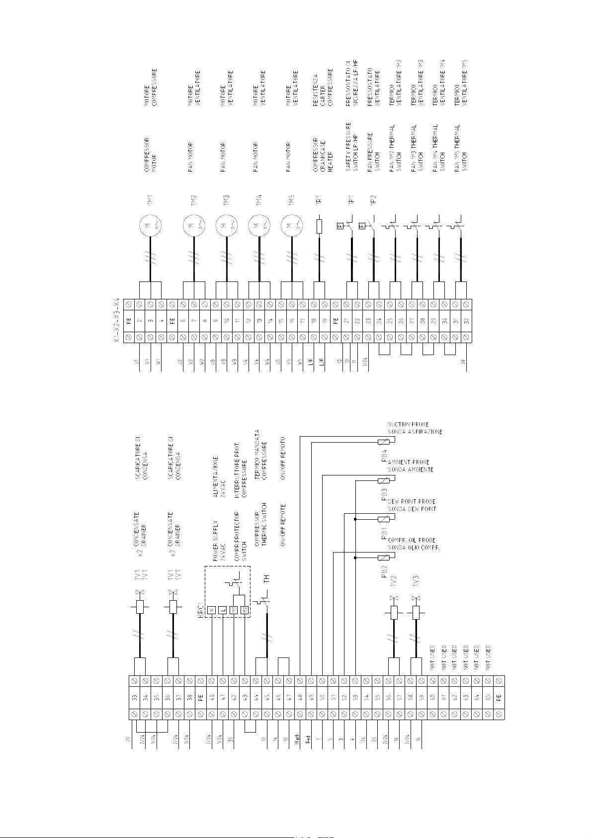
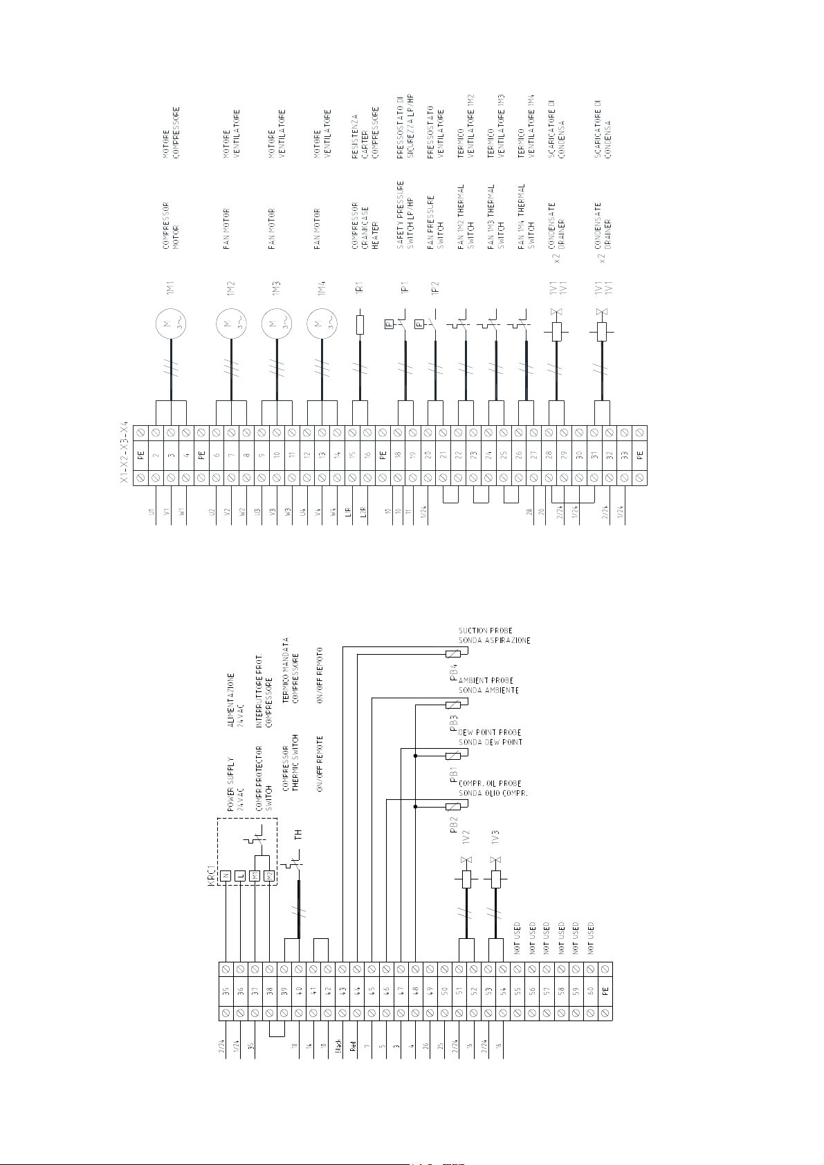
Terminal blocks (Timed version)
DMN FST Kaeltetrockner DFLO150-1360 (Rev-06) –EN-20121100
36
Page 38
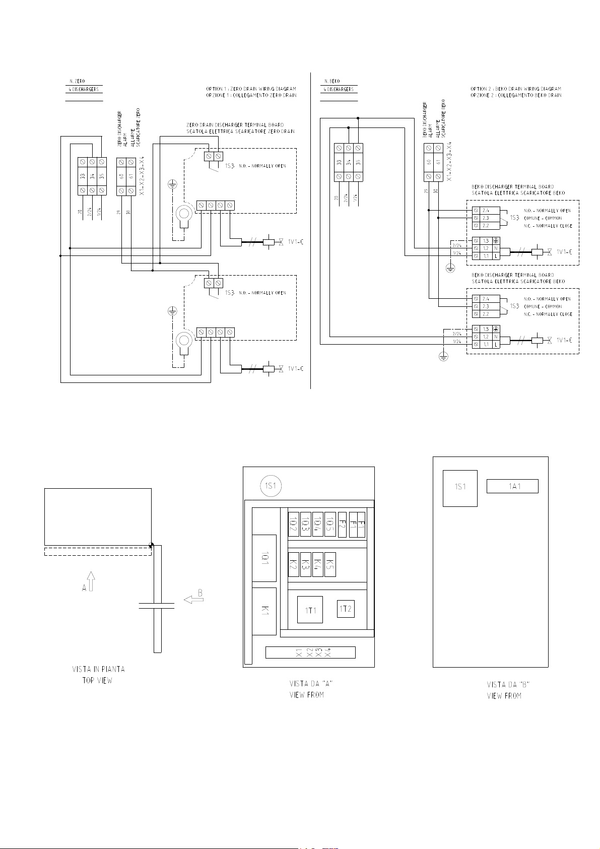
Terminal blocks (Zero Drain & Beko drain)
Components layout
DMN FST Kaeltetrockner DFLO150-1360 (Rev-06) –EN-20121100
37
Page 39
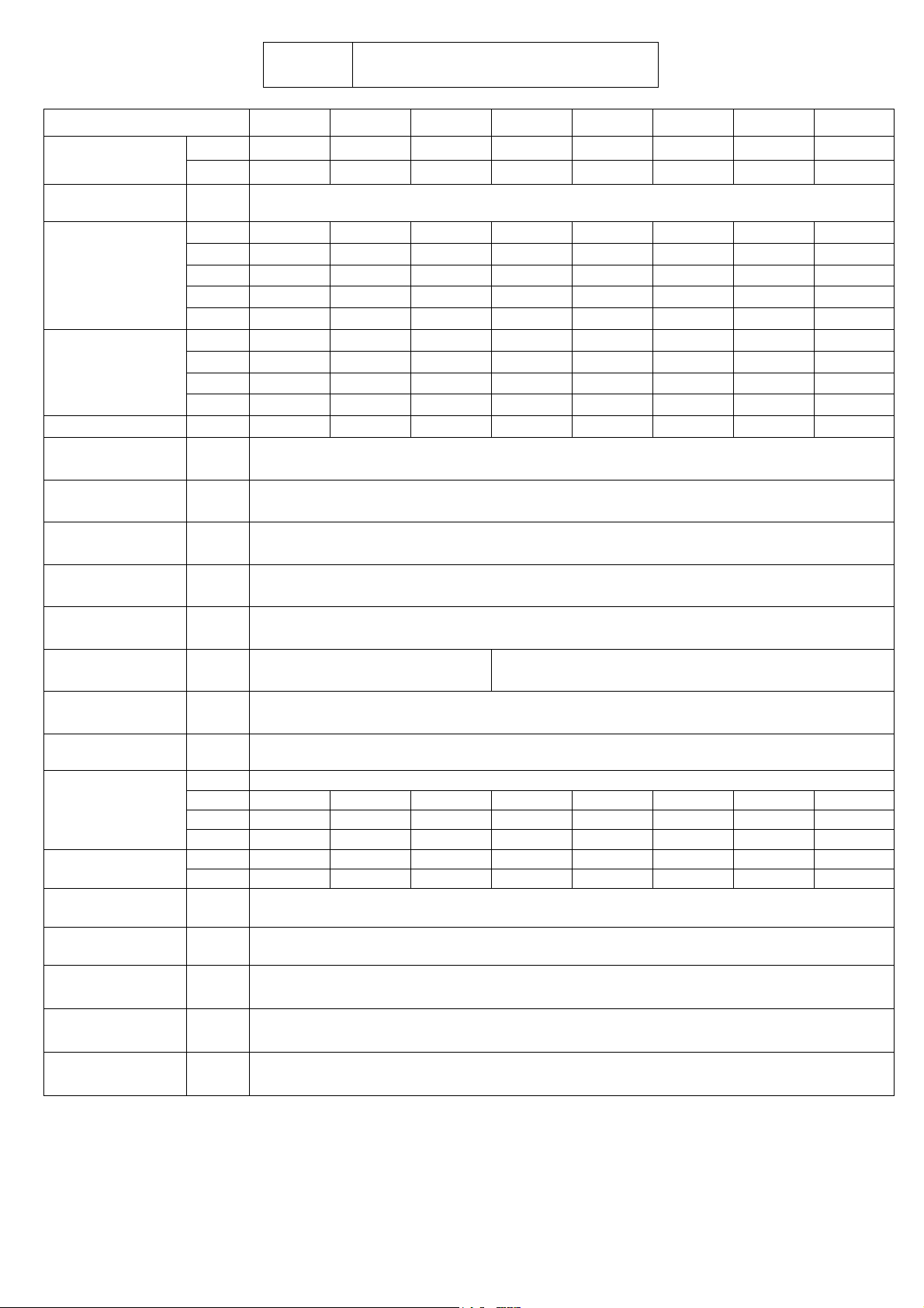
(C)
MODEL
AIR FLOW RATE*
POW SUPPLY
1M1
COMPRESSOR
1M2
FAN MOTOR
CONNECTION G
AIR T
AIR T MAX
AMB T
AMB T MAX
PRESS W
AIR PRESS MAX
DEW POINT*
SOUND
PRESSURE LEVEL
REFRIGERANT
W
WEIGHT
EVAP. TEMP.*
SUCTION TEMP.*
DISCH. PRESS.*
FAN PRESSURE
SWITCH SETTING
HP SWITCH
SETTING
m3/h
cfm
VOLT/
PH/HZ
kW
Max kW
RLA
FLA
LRA
QTY
HP
RLA
LRA
°C
°F
°C
°F
°C
°F
°C
°F
bar
psi
bar
psi
°C
°F
dB
TYPE
KG
LB
OZ
KG
LB
°C
°F
°C
°F
barg
psig
barg
psig
barg
psig
DATA SHEET
DFLO150 DFLO180 DFLO225 DFLO270 DFLO360 DFLO420 DFLO530 DFLO600
1500 1800 2250 2700 3600 4200 5300 6000
883 1059 1324 1589 2119 2472 3119 3531
400/3/50
2,78 2,78 3,54 4,99 6,29 7,29 9,52 9,52
4,81 4,81 5,30 7,44 9,81 11,42 15,14 15,14
6,72 6,72 5,94 9,33 12,5 14,5 17,6 17,6
8,94 8,94 8,73 12,97 16,9 19,6 24,9 24,9
50 50 70 87 130 130 145 145
1 1 1 1 2 2 2 2
1 1 1 1 1 1 1 1
1,35 1,35 1,35 1,35 1,35 1,35 1,35 1,35
1,70 1,70 1,70 1,70 1,70 1,70 1,70 1,70
3" BSP 3" BSP " 3" BSP DN 100 DN 125 DN 125 DN 150 DN 150
35
95
55
131
25
77
45
113
7
102
14
203
3 (ISO CLASS 4)
37 (ISO CLASS 4)
78
R407C
4,9 4,9 5,6 6,0 8,7 9,0 9,5 11
10,80 10,80 12,34 13,23 19,18 19,84 20,94 24,25
172,8 172,8 197,5 212 307 318 335 388
234 234 260 330 420 520 620 720
516 516 573 728 926 1146 1367 1587
1 – 2
34 – 35,5
4 – 6
39 – 43
13 – 18
188 – 261
15 – 19
218 – 276
28
406
13
188
DMN FST Kaeltetrockner DFLO150-1360 (Rev-06) –EN-20121100
38
Page 40
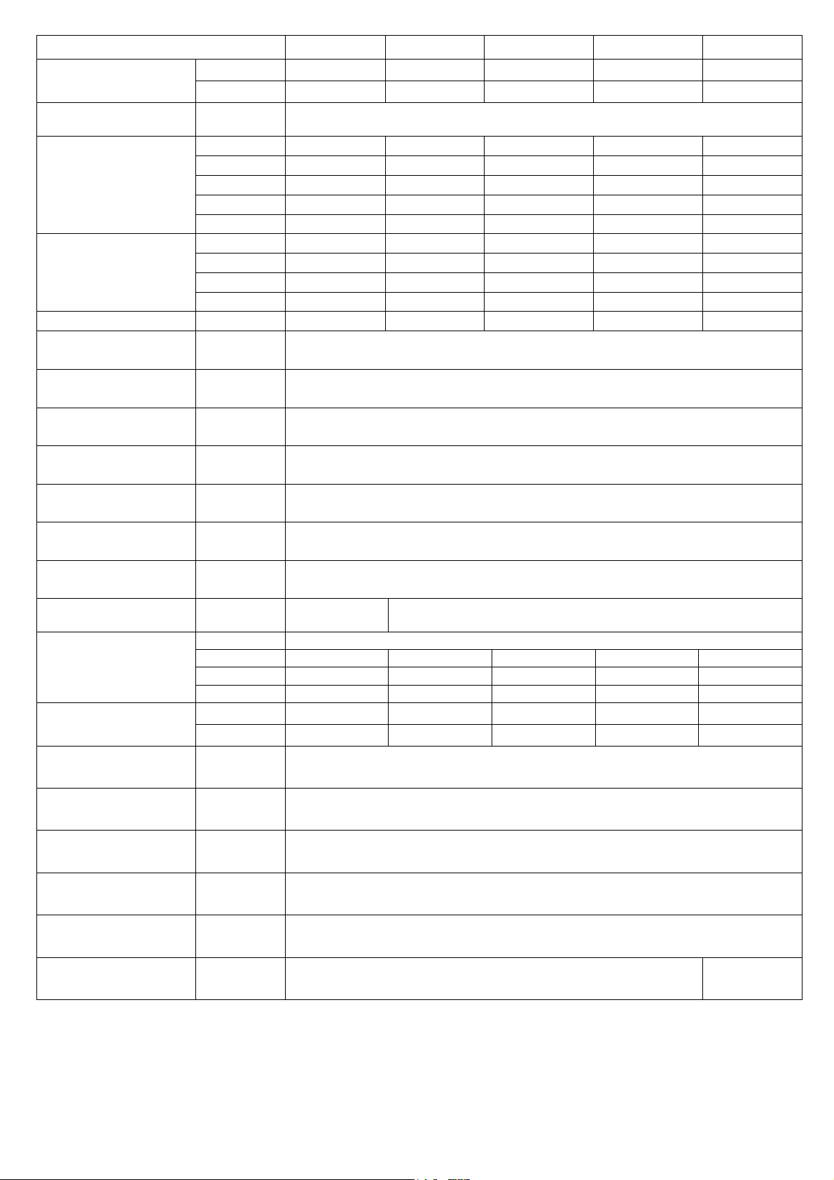
MODEL
AIR FLOW RATE*
POW SUPPLY
1M1
COMPRESSOR
1M2
FAN MOTOR
CONNECTION G
AIR T
AIR T MAX
AMB T
AMB T MAX
PRESS W
AIR PRESS MAX
DEW POINT*
SOUND PRESSURE
LEVEL
m3/h
cfm
VOLT/
PH/HZ
kW
Max kW
RLA
FLA
LRA
QTY
HP
RLA
LRA
°C
°F
°C
°F
°C
°F
°C
°F
bar
psi
bar
psi
°C
°F
dB
DFLO680 DFLO880 DFLO1000 DFLO1200 DFLO1360
6800 8800 10000 12000 13600
4002 5180 5886 7063 8005
10,98 14,96 14,96 18,16 22,32
17,34 23,86 23,86 29,03 34,96
20,69 26,57 26,57 32,69 38
29,25 38,55 38,55 47,19 54,99
175 215 215 270 320
2 3 3 3 4
1 1 1 1 1
1,54 1,35 1,35 1,54 1,54
1,9 1,70 1,70 1,9 1,9
DN 150 DN 200 DN 200 DN 200 DN 200
78 79
TYPE
REFRIGERANT
KG
LB
OZ
W
WEIGHT
EVAP. TEMP.*
SUCTION TEMP.*
DISCH. PRESS.*
FAN PRESSURE
SWITCH SETTING
HP SWITCH SETTING
SAFETY VALVE
SETTING
*Rating conditions of: 35°C (95°F) and 100 psig air Inlet, 25°C (77°F) ambient temperature
Performance and specifications + / - 5%
KG
LB
°C
°F
°C
°F
barg
psig
barg
psig
barg
psig
barg
psig
14 21,25 25 26 27
30,86 46,85 55,12 57,32 59,52
494 750 882 836 952
735 1080 1150 1230 1350
1620 2381 2535 2712 2976
400/3/50
35
95
55
131
25
77
45
113
7
102
13
188
3 (ISO CLASS 4)
37 (ISO CLASS 4)
R407C
1 – 2
34 – 35,5
4 – 6
39 – 43
13 – 18
188 – 261
15 – 19
218 – 276
28
406
- 31
- 450
DMN FST Kaeltetrockner DFLO150-1360 (Rev-06) –EN-20121100
39
Page 41
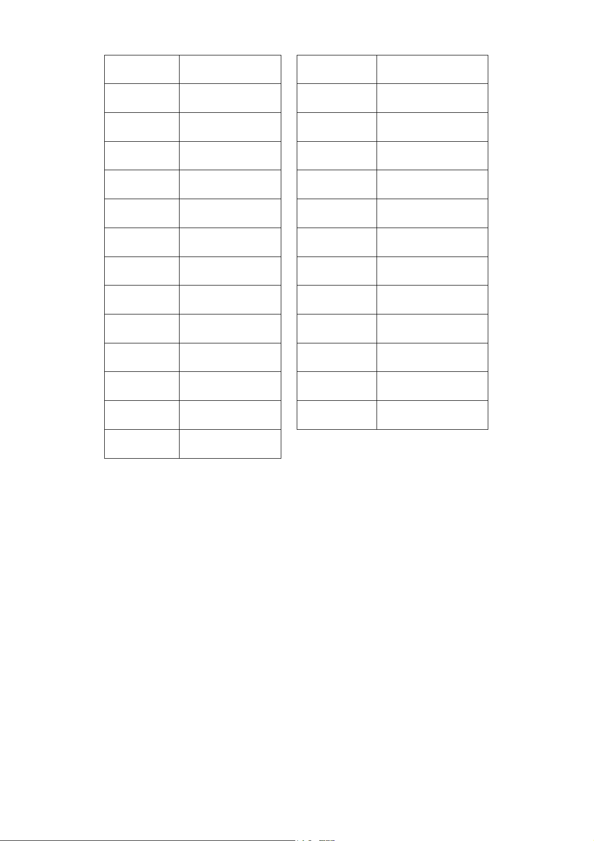
AIR FLOW RATE
POW SUPPLY
HP
kW
Max kW
RLA
FLA
LRA
CONN
AIR T
AIR T MAX
Air flow rate
Power supply
Nominal power
Nominal consumption
Full load consumption
Nominal Current
Full load current
Locked rotor current
Air connections
Air inlet temperature
Max. air inlet temperature
PRESS MAX
DEWP
REF
W
TOTAL A
EVAP. TEMP
SUCTION TEMP
FAN PRESSURE
SWITCH SETTING
SAFETY VALVE
SETTING
DISCH. PRESS.
HP SWITCH
SETTING
Max, pressure
Pressure dew point
Refrigerant
Weight
Total current
Evaporation temperature
Suction temperature
Fan pressure Switch setting
Safety valve setting
Discharge pressure
High pressure switch setting
AMB T
AMB T MAX
PRESS W
Ambient temperature
Max. ambient temperature
Working pressure
MIN CIRCUIT
AMPACITY
DB(A)
Minimum circuit ampacity
Sound pressure level
DMN FST Kaeltetrockner DFLO150-1360 (Rev-06) –EN-20121100
40
Page 42
(D)
psi
°C 25 30 35 40 42 45
°F
FC2
°C 30 35 40 45 50 55
°F
FC3
(E)
CORRECTION FACTORS
Correction factor for working pressure
bar 5 6 7 8 9 10 11 12 13
73 87 102 116 131 145 160 174 188
FC1
Correction factor for ambient temperature
Correction factor for inlet air temperature
Calculation of the dryer REAL FLOW RATE = nominal dryer flow rate x FC1 x FC2 x FC3
Calculation of the GIVEN FLOW RATE to select a suitable dryer = given flow rate ÷ FC1 ÷ FC2 ÷ FC3
0,85 0,93 1 1,06 1,11 1,15 1,18 1,20 1,22
77 86 95 104 107,6 113
1,00 0,96 0,92 0,88 0,85 0,8
86 95 104 113 122 131
1,20 1,00 0,85 0,71 0,58 0,49
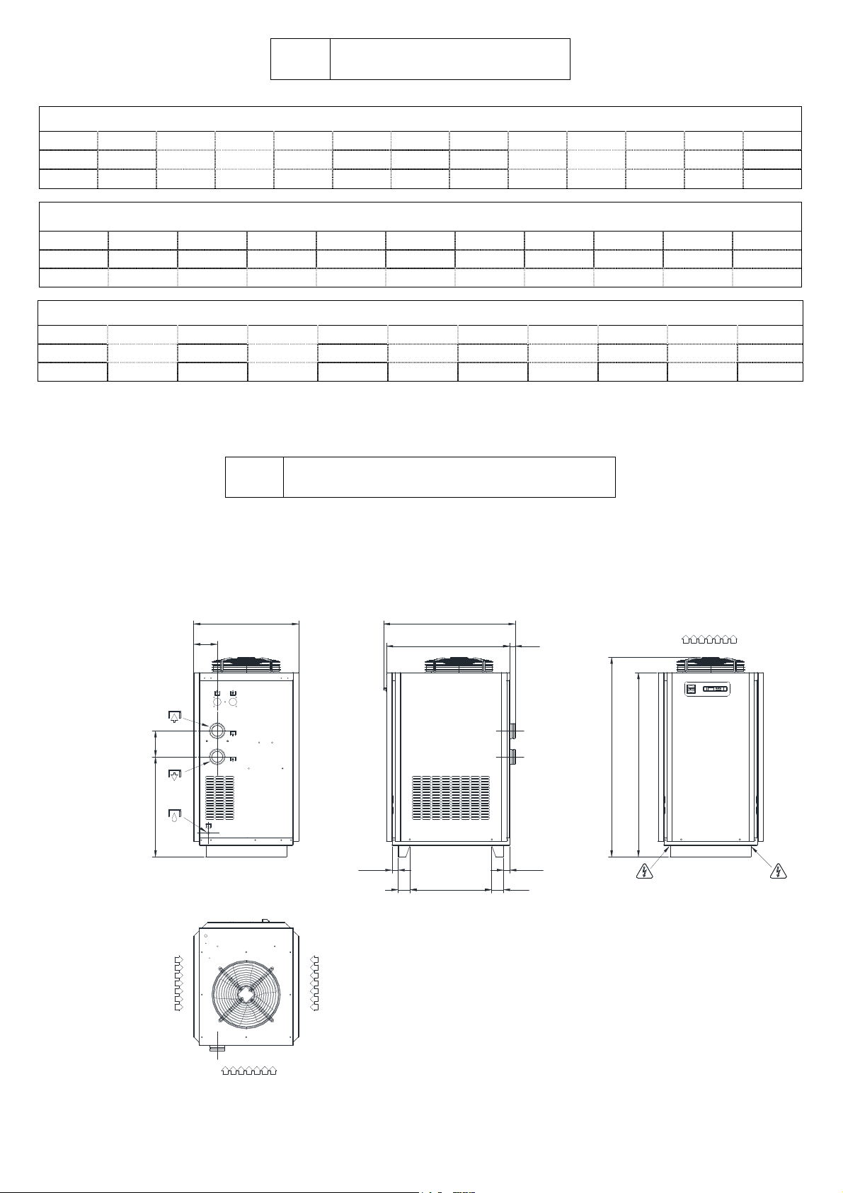
DRYER DIMENSIONS
DFLO150 – DFLO180 – DFLO225
806
181
200
772
47,5
1012
948
(624)
93
93
41
47,5
1539
1422
AIR FLOW
AIR FLOW
AIR FLOW
DMN FST Kaeltetrockner DFLO150-1360 (Rev-06) –EN-20121100
AIR FLOW
41
Page 43
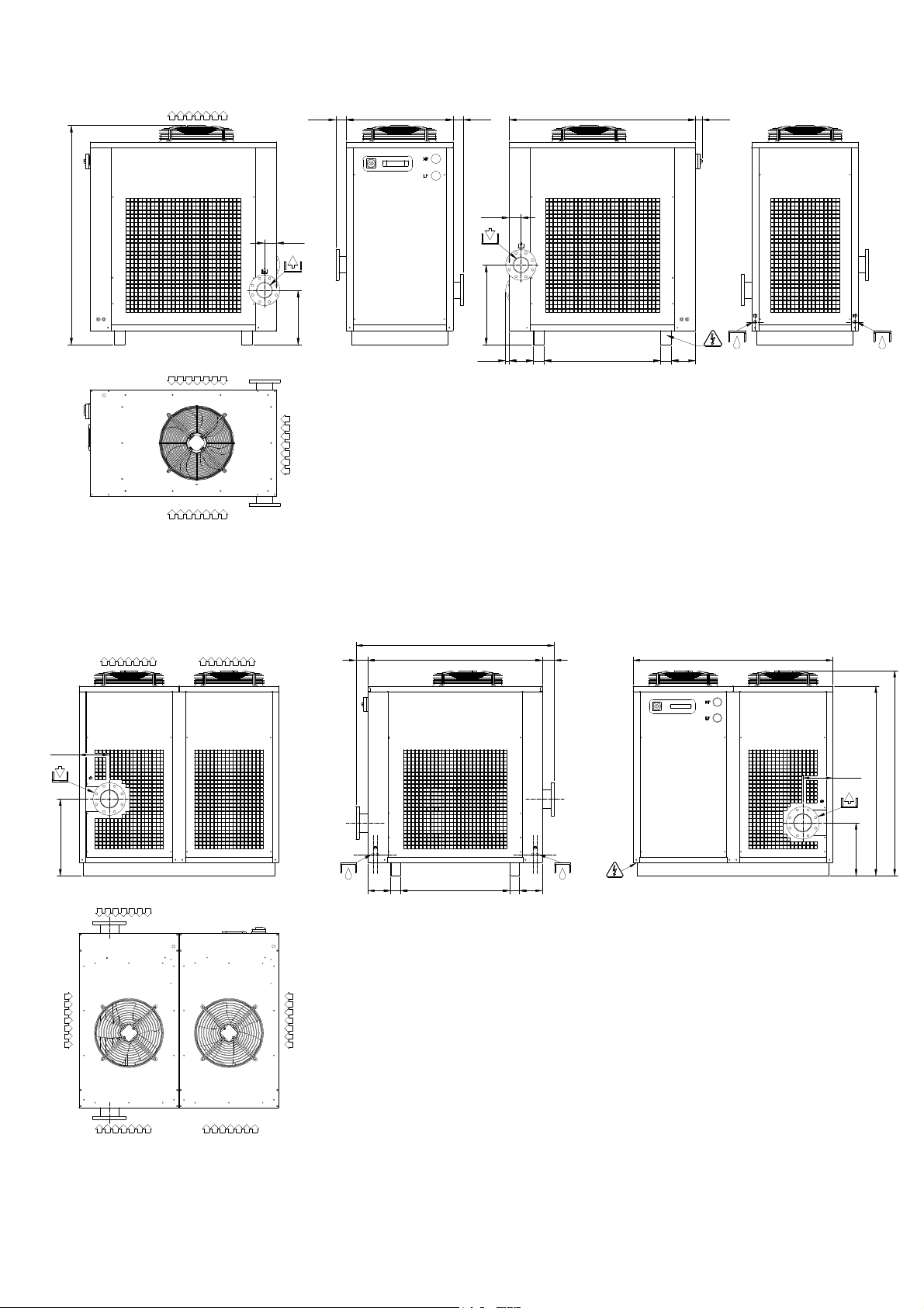
DFLO270
AIR FLOW
1554
85
755
7373
85
1319
46
387
AIR FLOW
AIR FLOW
AIR FLOW
566
172 76 823 76 172
25
DFLO360 – DFLO420 – DFLO530 – DFLO600 –DFLO680
COOLING AIR FLOW COOLING AIR FLOW
228
(1500)
1319 9191
1510
228
(1555)
1437
582
76 823 76
172
COOLING AIR FLOW
COOLING AIR FLOW
COOLING AIR FLOW COOLING AIR FLOW
COOLING AIR FLOW
DMN FST Kaeltetrockner DFLO150-1360 (Rev-06) –EN-20121100
402
172
42
Page 44
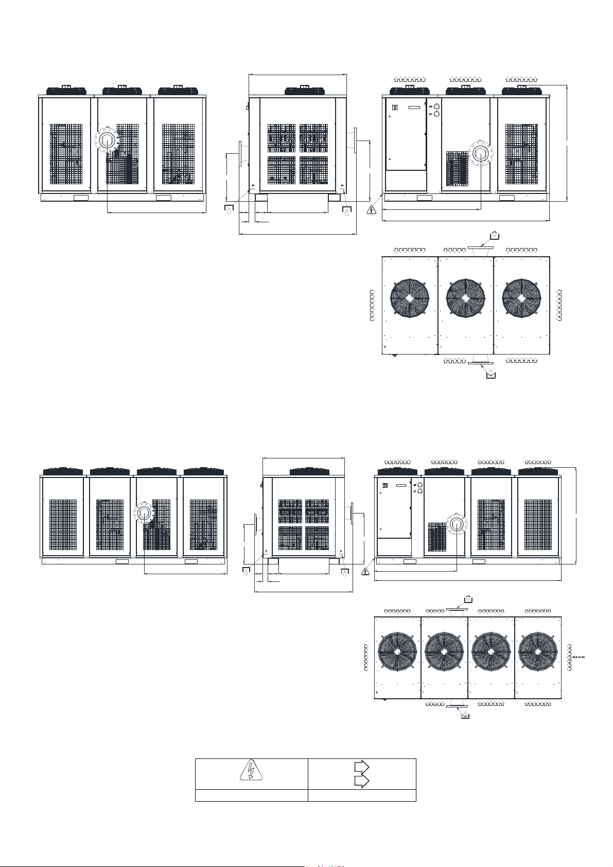
DFLO880 – DFLO1000 – DFLO1200
1320
AIR FLOW AIR FLOW AIR FLOW
1570
1335
645
13582170 815
1590
DFLO1360
1320
AIR FLOW
825
1335
2270
AIR FLOW AI R FLOW AIR FLOW
AIR FLOW
AIR FLOW AIR FLOW AIR FLOW AIR FLOW
AIR INLET DN 200 PN16
AIR FLOW
AIR FLOW
AIR OUTLET DN 200 PN16
1565
AIR FLOW
825
1335
AIR FLOW AIR FLOW AIR FLOW
AIR FLOW
3025
AIR INLET DN 200 PN16
AIR FLOW
AIR OUTLET DN 200 PN16
AIR FLOW
AIR FLOW
1335
645
13582170 815
1590
Power supply Air flow
DMN FST Kaeltetrockner DFLO150-1360 (Rev-06) –EN-20121100
43
Page 45
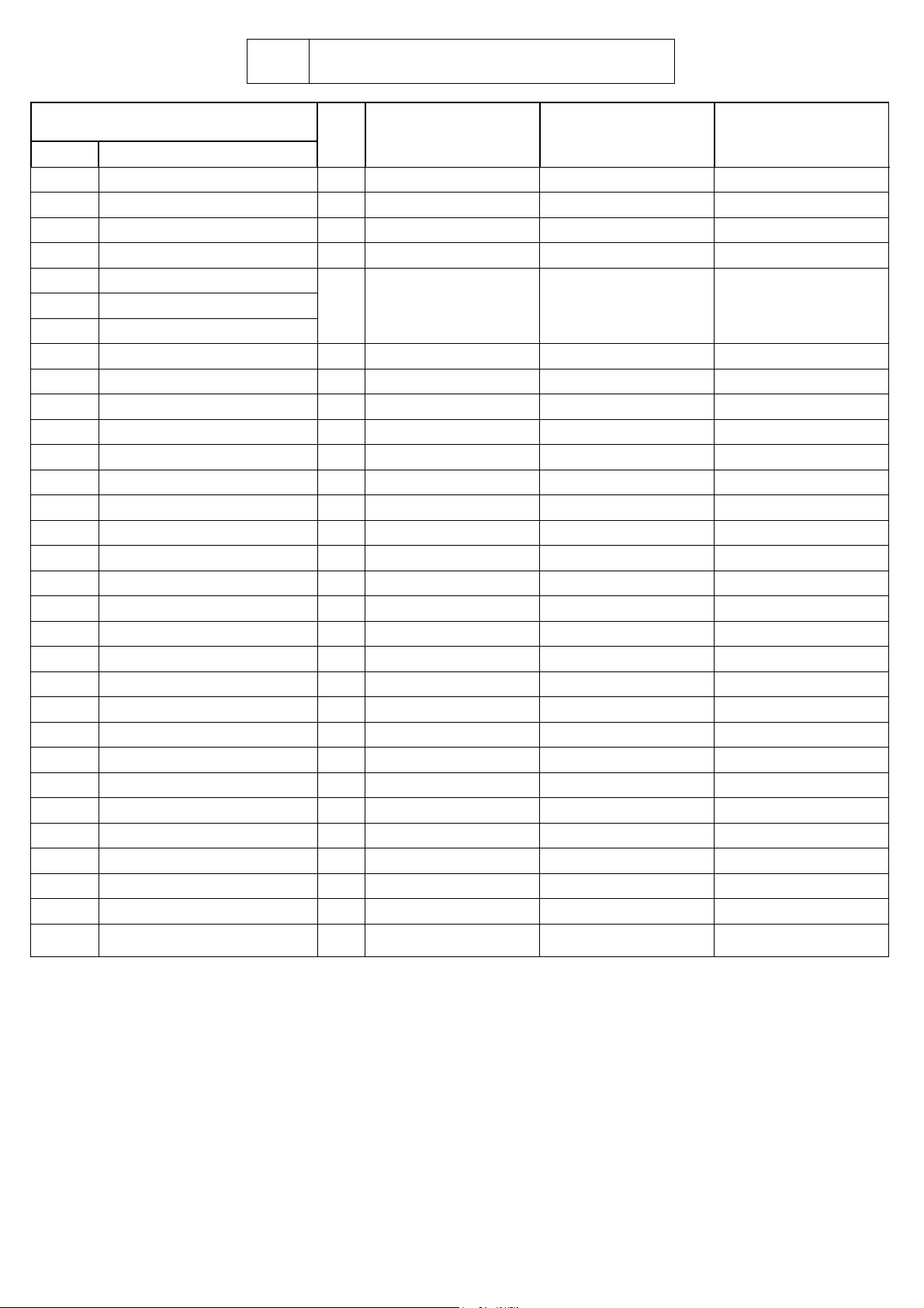
(F)
SSC*
Model
Pos Element
1A1
PB1-3
PB4
1M1
1M2
VT
G
1P1
1P2
1V1
1B1
CND
FF
SC
STC
VB
IM
VG
TH
1T1
1T2
F1
F2
F3
PFU
RF
K1
K2
1R1
RD
Electronic Controller A 305.0058.01.00 305.0058.01.00 305.0058.01.00
Temperature probe A 243.1966.00.00 243.1966.00.00 243.1966.00.00
Temperature probe A 243.0030.00.00 243.0030.00.00 243.0030.00.00
Refrigerant compressor C 203.0005.00.00 203.0005.00.00 203.0009.00.00
Fan Motor
Fan blade
Grid
High pressure Switch A 245.1950.00.00 245.1950.00.00 245.1950.00.00
Fan pressure Switch A 245.0077.00.00 245.0077.00.00 245.0077.00.00
Complete solenoid drain valve B 240.0110.00.00 240.0110.00.00 240.0110.00.00
Drain solenoid valve coil A 240.0111.00.00 240.0111.00.00 240.0111.00.00
Condenser C 921.1917.00.00 921.1917.00.00 921.1917.00.00
Dehydrator filter C 630.0118.00.00 630.0118.00.00 630.0118.00.00
Heat exchanger base C 920.0090.01.01 920.0090.01.01 920.0103.01.01
Control panel cover 711.1936.00.00 711.1936.00.00 711.1936.00.00
By-pass hot gas valve B 142.0134.00.00 142.0134.00.00 142.0134.00.00
Moisture indicator C 143.0075.00.00 143.0075.00.00 143.0075.00.00
Freon filling valve 910.0050.00.00 910.0050.00.00 910.0050.00.00
Thermostat A 242.0072.00.00 242.0072.00.00 242.0072.00.00
Transformer C 241.0048.00.00 241.0048.00.00 241.0048.00.00
Board transformer A 241.0054.00.00 241.0054.00.00 241.0054.00.00
Primary fuse A 331.0041.00.00 331.0041.00.00 331.0041.00.00
24V secondary circuit fuse A 331.0033.00.00 331.0033.00.00 331.0033.00.00
Phase control relais fuse A 331.1969.00.00 331.1969.00.00 331.1969.00.00
Fuse holder 322.0058.00.00 322.0058.00.00 322.0058.00.00
Phase control relais A 251.1018.00.00 251.1018.00.00 251.1018.00.00
Compressor contactor switch A 252.0090.00.00 252.0090.00.00 252.0090.00.00
Fan contactor switch A 252.0089.00.00 252.0089.00.00 252.0089.00.00
Compressor crankcase heater C 230.0016.00.00 230.0016.00.00 230.0017.00.00
Level sensor (Reed) B 904.0180.01.01 904.0180.01.01 904.0180.01.01
BASIC SPARE PARTS
SSP DFLO150 DFLO180 DFLO225
B 210.1920.00.00 210.1920.00.00 210.1916.00.00
(BEKO)
Condensate drain C 345.0008.00.00 345.0008.00.00 345.0008.00.00
*=OPTIONAL
DMN FST Kaeltetrockner DFLO150-1360 (Rev-06) –EN-20121100
44
Page 46
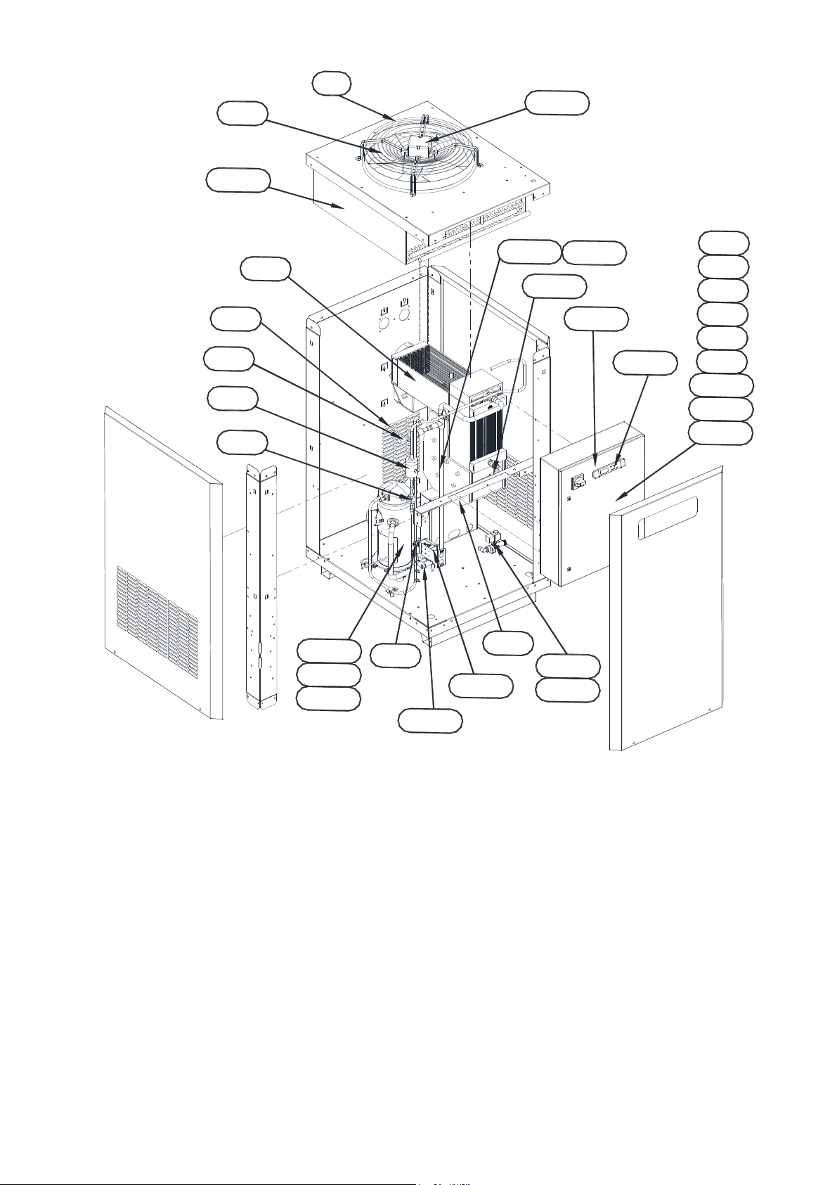
G
1
M
B
P
2
K
P
1
1
F
F
F
K
R
T
T
2
1
F
3
2
1
F
U
2
1
3
P
B
4
B
1
S
T
C
1
A
1
V
C
F
V
V
B
I
N
F
G
M
T
D
S
P
C
1
M
1
1
R
1
P
B
2
DMN FST Kaeltetrockner DFLO150-1360 (Rev-06) –EN-20121100
T
H
R
D
1
V
1
1
P
2
1
P
1
1
B
1
45
Page 47
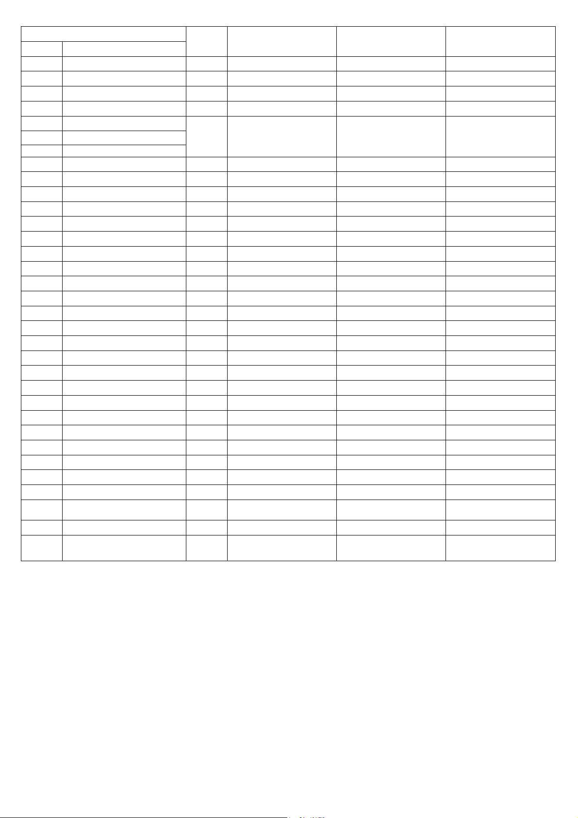
Model
Pos Element
1A1
PB1-3
PB4
1M1
1M2
VT
G
1P1
1P2
CND
FF
SC
STC
VB
SLI
IM
VG
TH
MHP
MLP
1T1
1T2
F1
F2
F3
PFU
RF
K1
K2
1R1
1V1
1B1
SSC*
(BEKO)
*=OPTIONAL
DMN FST Kaeltetrockner DFLO150-1360 (Rev-06) –EN-20121100
Electronic Controller A 305.0058.01.00 305.0058.01.00 305.0058.01.00
Temperature probe A 243.1966.00.00 243.1966.00.00 243.1966.00.00
Temperature probe A 243.0030.00.00 243.0030.00.00 243.0030.00.00
Refrigerant compressor C 203.0007.00.00 203.1044.00.00 203.1045.00.00
Fan Motor
Fan blade
Grid
High pressure Switch A 245.1950.00.00 245.1950.00.00 245.1950.00.00
Fan pressure Switch A 245.0077.00.00 245.0077.00.00 245.0077.00.00
Condenser C 921.1935.00.00 921.1934.00.00 921.1934.00.00
Dehydrator filter C 630.0118.00.00 630.0114.00.00 630.0114.00.00
Heat exchanger base C 920.0066.01.01 920.0066.01.01 920.0062.01.01
Control panel cover 711.1936.00.00 711.1936.00.00 711.1936.00.00
By-pass hot gas valve B 142.0134.00.00 142.0089.00.00 142.0089.00.00
Liquid separator 910.2323.00.00 910.2325.00.00 910.2325.00.00
Moisture indicator C 143.0075.00.00 143.0076.00.00 143.0076.00.00
Freon filling valve 910.0050.00.00 910.0050.00.00 910.0050.00.00
Thermostat A 242.0072.00.00 242.0072.00.00 242.0072.00.00
High pressure freon manometer
Low pressure freon manometer C 143.0063.00.00 143.0063.00.00 143.0063.00.00
Transformer C 241.0048.00.00 241.0050.00.00 241.0050.00.00
Board transformer A 241.0054.00.00 241.0054.00.00 241.0054.00.00
Primary fuse A 331.0041.00.00 331.0040.00.00 331.0040.00.00
24V secondary circuit fuse A 331.0033.00.00 331.0033.00.00 331.0033.00.00
Phase control relais fuse A 331.1969.00.00 331.1969.00.00 331.1969.00.00
Fuse holder 322.0058.00.00 322.0058.00.00 322.0058.00.00
Phase control relais A 251.1018.00.00 251.1018.00.00 251.1018.00.00
Compressor contactor switch A 252.0091.00.00 252.0092.00.00 252.0092.00.00
Fan contactor switch A 252.0089.00.00 252.0089.00.00 252.0089.00.00
Compressor crankcase heater C 230.0018.00.00 230.1968.00.00 230.1968.00.00
Complete solenoid drain
valve
Drain solenoid valve coil A 240.0111.00.00 240.0111.00.00 240.0111.00.00
Condensate drain C 345.0008.00.00 345.0008.00.00 345.0008.00.00
SSP DFLO270 DFLO360 DFLO420
B 210.1920.00.00 210.1920.00.00 210.1920.00.00
C 143.0062.00.00 143.0062.00.00 143.0062.00.00
B 240.0110.00.00 240.0110.00.00 240.0110.00.00
46
Page 48
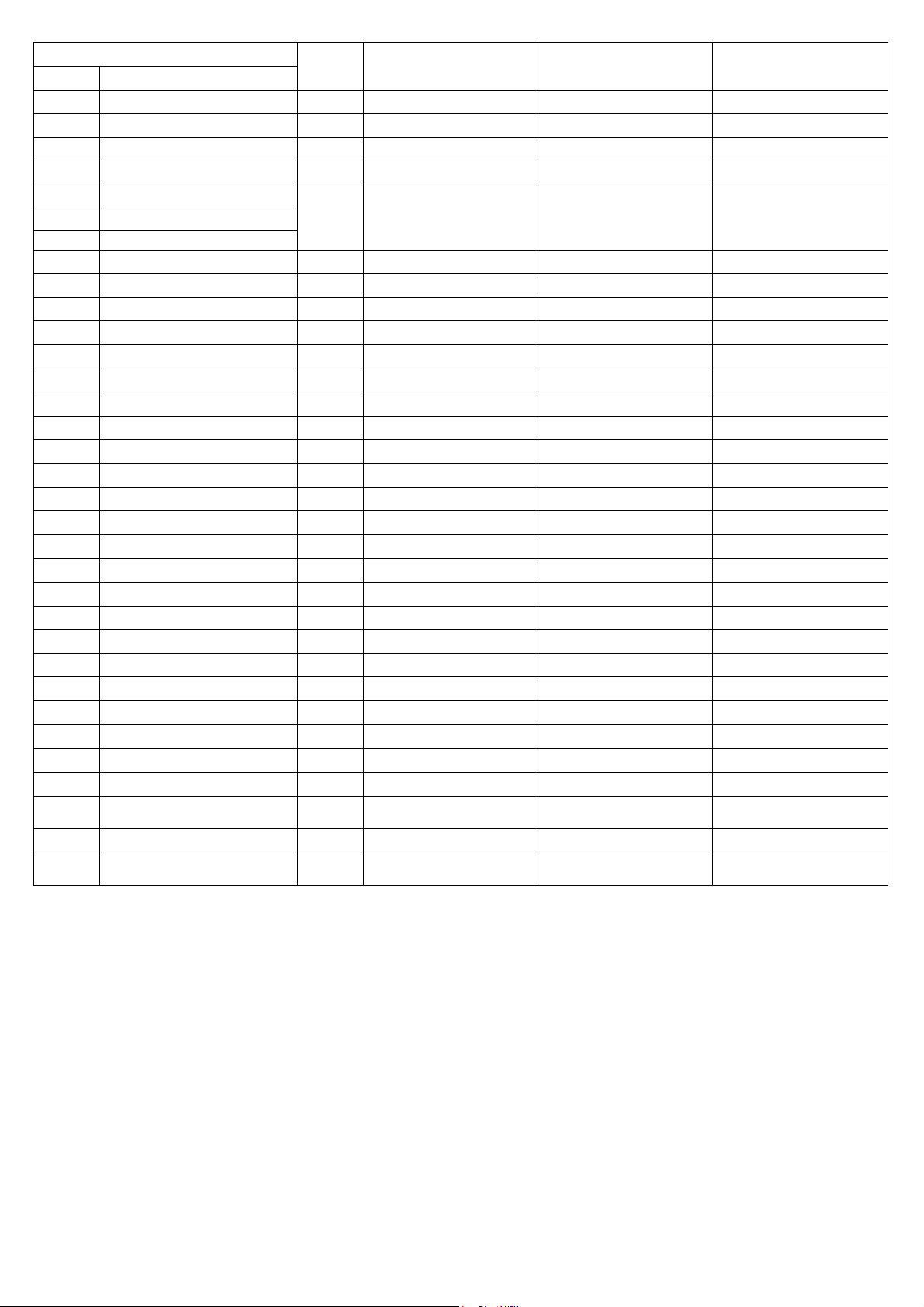
SSC*
Model
Pos Element
1A1
PB1-3
PB4
1M1
1M2
VT
G
1P1
1P2
CND
FF
SC
STC
VB
SLI
IM
VG
TH
MHP
MLP
1T1
1T2
F1
F2
F3
PFU
RF
K1
K2
1R1
1V1
1B1
Electronic Controller A 305.0058.01.00 305.0058.01.00 305.0058.01.00
Temperature probe A 243.1966.00.00 243.1966.00.00 243.1966.00.00
Temperature probe A 243.0030.00.00 243.0030.00.00 243.0030.00.00
Refrigerant compressor C 203.1048.00.00 203.1048.00.00 203.1014.00.01
Fan Motor
Fan blade
Grid
High pressure Switch A 245.1950.00.00 245.1950.00.00 245.1950.00.00
Fan pressure Switch A 245.0077.00.00 245.0077.00.00 245.0077.00.00
Condenser C 921.1935.00.00 921.1935.00.00 921.1935.00.00
Dehydrator filter C 630.0115.00.00 630.0115.00.00 630.0115.00.00
Heat exchanger base C 920.0062.01.01 920.0062.01.01 920.0062.01.01
Control panel cover 711.1936.00.00 711.1936.00.00 711.1936.00.00
By-pass hot gas valve B 142.0089.00.00 142.0089.00.00 142.0089.00.00
Liquid separator 910.2325.00.00 910.2325.00.00 910.2325.00.00
Moisture indicator C 143.0077.00.00 143.0077.00.00 143.0077.00.00
Freon filling valve 910.0050.00.00 910.0050.00.00 910.0050.00.00
Thermostat A 242.0072.00.00 242.0072.00.00 242.0072.00.00
High pressure freon manometer
Low pressure freon manometer C 143.0063.00.00 143.0063.00.00 143.0063.00.00
Transformer C 241.0050.00.00 241.0050.00.00 241.0050.00.00
Board transformer A 241.0054.00.00 241.0054.00.00 241.0054.00.00
Primary fuse A 331.0040.00.00 331.0040.00.00 331.0040.00.00
24V secondary circuit fuse A 331.0033.00.00 331.0033.00.00 331.0033.00.00
Phase control relais fuse A 331.1969.00.00 331.1969.00.00 331.1969.00.00
Fuse holder 322.0058.00.00 322.0058.00.00 322.0058.00.00
Phase control relais A 251.1018.00.00 251.1018.00.00 251.1018.00.00
Compressor contactor switch A 252.0093.00.00 252.0093.00.00 252.0094.00.00
Fan contactor switch A 252.0089.00.00 252.0089.00.00 252.0089.00.00
Compressor crankcase heater C 230.1968.00.00 230.1968.00.00 230.1985.00.00
Complete solenoid drain
valve
Drain solenoid valve coil A 240.0111.00.00 240.0111.00.00 240.0111.00.00
SSP DFLO530 DFLO600 DFLO680
B 210.1920.00.00 210.1920.00.00 210.1916.00.00
C 143.0062.00.00 143.0062.00.00 143.0062.00.00
B 240.0110.00.00 240.0110.00.00 240.0110.00.00
(BEKO)
*=OPTIONAL
DMN FST Kaeltetrockner DFLO150-1360 (Rev-06) –EN-20121100
Condensate drain C 345.0008.00.00 345.0008.00.00 345.0008.00.00
47
Page 49
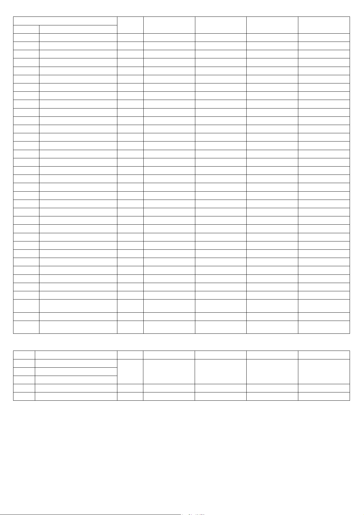
SSC*
Model
Pos Element
1A1
PB1-3
PB4
1M1
KRC1
RF
1P1
FF
FCR
SC
STC
VB
PVB
1V3
1B3
SLI
IM
VG
1V2
1B2
TH
VSR
MHP
MLP
1T1
1T2
F1
F2
F3
PFU
K1
1R1
1V1
1B1
Electronic Controller A 305.0058.01.00 305.0058.01.00 305.0058.01.00 305.0058.01.00
Temperature probe A 243.1966.00.00 243.1966.00.00 243.1966.00.00 243.1966.00.00
Temperature probe A 243.0030.00.00 243.0030.00.00 243.0030.00.00 243.0030.00.00
Refrigerant compressor C 203.1049.00.00 203.1049.00.00 203.1043.00.00 203.1047.00.00
Protection module A 244.0146.00.00 244.0146.00.00 244.0146.00.00 244.0146.00.00
Phase control relais A - - - -
High pressure Switch A 245.0088.00.00 245.0088.00.00 245.0088.00.00 245.0088.00.00
Dehydrator filter 630.1989.00.00 630.1989.00.00 630.1989.00.00 630.0113.00.00
Filter cartridge C 2 x 630.1993.00 2 x 630.1993.00 2 x 630.1993.00 2 x 630.1993.00
Heat exchanger base C 920.0062.01.01 920.0062.01.01 920.0062.01.01 920.0062.01.01
Control panel cover - - - -
By-pass hot gas valve module B 142.0139.00.00 142.0139.00.00 142.0140.00.00 142.0140.00.00
By-pass hot gas pilot valve B 142.0138.00.00 142.0138.00.00 142.0138.00.00 142.0138.00.00
By-pass solenoid valve body B 140.0142.01.00 140.0142.01.00 140.0150.01.00 140.0150.01.00
By-pass solenoid valve coil A 240.1976.00.00 240.1976.00.00 240.1976.00.00 240.1976.00.00
Liquid separator - - - Moisture indicator C 143.0042.00.00 143.0042.00.00 143.0042.00.00 143.0069.00.00
Freon filling valve 910.0050.00.00 910.0050.00.00 910.0050.00.00 910.0050.00.00
Liquid valve B 140.1840.01.00 140.1840.01.00 140.1840.01.00 140.0142.01.00
Liquid valve coil A 240.1976.00.00 240.1976.00.00 240.1976.00.00 240.1976.00.00
Thermostat A 242.0072.00.00 242.0072.00.00 242.0072.00.00 242.0072.00.00
Safety valve A - - - 140.0158.00.00
High pressure freon manometer
Low pressure freon manometer C 143.0063.00.00 143.0063.00.00 143.0063.00.00 143.0063.00.00.00
Transformer C 241.0050.00.00 241.0050.00.00 241.0050.00.00 241.0081.00.00
Board transformer A 241.0054.00.00 241.0054.00.00 241.0054.00.00 241.0054.00.00
Primary fuse A 331.0040.00.00 331.0040.00.00 331.0040.00.00 331.0040.00.00
24V secondary circuit fuse A 331.0048.00.00 331.0048.00.00 331.0048.00.00 331.0034.00.00
Phase control relais fuse A 331.1969.00.00 331.1969.00.00 331.1969.00.00 331.1969.00.00
Fuse holder 322.0058.00.00 322.0058.00.00 322.0058.00.00 322.0058.00.00
Compressor contactor switch A 252.0083.00.00 252.0083.00.00 252.0083.00.00 252.0084.00.00
Compressor crankcase heater C 230.1970.00.00 230.1970.00.00 230.1970.00.00 230.1970.00.00
Complete solenoid drain
valve
Drain solenoid valve coil A 240.0111.00.00 240.0111.00.00 240.0111.00.00 240.0111.00.00
SSP DFLO880 DFLO1000 DFLO1200 DFLO1360
C 143.0062.00.00 143.0062.00.00 143.0062.00.00 143.0062.00.00.00
B 240.0110.00.00 240.0110.00.00 240.0110.00.00 240.0110.00.00
(BEKO)
*=OPTIONAL
CND
1M2
VT
G
1P2
K2
DMN FST Kaeltetrockner DFLO150-1360 (Rev-06) –EN-20121100
Condensate drain C 345.0008.00.00 345.0008.00.00 345.0008.00.00 345.0008.00.00
Condenser C 921.1935.00.00 921.1935.00.00 921.1935.00.00 921.1935.00.00
Fan Motor
Fan blade
Grid
Fan pressure Switch A 245.0077.00.00 245.0077.00.00 245.0077.00.00 245.0077.00.00
Fan contactor switch A 252.0054.00.00 252.0054.00.00 252.0054.00.00 252.0054.00.00
B 210.1920.00.00 210.1920.00.00 210.1916.00.00 210.1916.00.00
48
Page 50
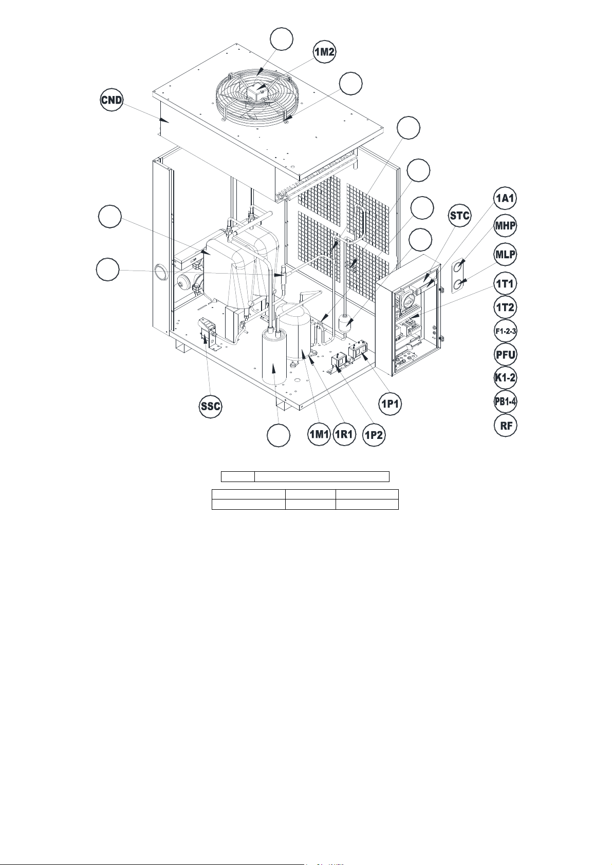
VT
SSP
G
TH
VG
SC
IM
FF
VB
SLI
Very important Important Suggested
Suggested spare parts
A B C
DMN FST Kaeltetrockner DFLO150-1360 (Rev-06) –EN-20121100
49
Page 51

 Loading...