

Page 1
REGULATORY COMPLIANCE
FSR'S ELECTRONIC PRODUCTS have been tested for compliance with: FCC Class A
and CE The Power Adapter has been tested for compliance with: UL, CSA and CE.
WARRANTY POLICY
This product is warranted against failures due to defective parts or faulty workmanship for
a period of one year after delivery to the original owner. During this period, FSR will make
any necessary repairs or replace the unit without charge for parts or labor. Shipping charges
to the factory or repair station must be prepaid by the owner, return-shipping charges, via
UPS / FedEx ground, will be paid by FSR.
FSR
This warranty applies only to the original owner and is not transferable. In addition, it does
not apply to repairs done by other than the FSR factory or Authorized Repair Stations.
This warranty shall be cancelable by FSR at its sole discretion if the unit has been
subjected to physical abuse or has been modified in any way without written authorization
from FSR. FSR’s liability under this warranty is limited to repair or replacement of the
defective unit.
FSR will not be responsible for incidental or consequential damages resulting from the use
or misuse of its products. Some states do not allow the exclusion of incidental or consequential damages, so the above limitations may not apply to you. This warranty gives you
specific legal rights, and you may also have other rights which vary from state to state.
Warranty claims should be accompanied by a copy of the original purchase invoice
showing the purchase date (if a Warranty Registration Card was mailed in at the time of
purchase, this is not necessary). Before returning any equipment for repair, please read the
important information on service below.
SERVICE
Before returning any equipment for repair, please be sure that it is adequately packed and
cushioned against damage in shipment, and that it is insured. We suggest that you save
the original packaging and use it to ship the product for servicing. Also, please enclose a
note giving your name, address, phone number and a description of the problem.
NOTE: all equipment being returned for repair must have a Return Authorization
(RMA) Number. To get a RMA Number, please call the
FSR Service Department (973-785-4347).
Please display your RMA Number prominently on the front of all packages.
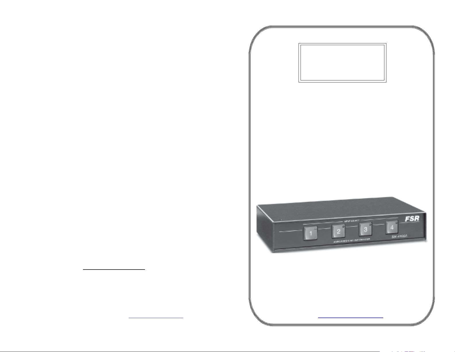
SN - 4100A
VGA
SWITCHER
FOUR BY ONE AUDIO/VIDEO SWITCHER
OPERATIONS MANUAL
Contact Information:
244 Bergen Boulevard,
West Paterson, NJ 07424
Tel: (973) 785-4347 · Fax: (973) 785-4207
E-Mail: sales@fsrinc.com · Web: http://www.fsrinc.com
issue date: 1-03
244 Bergen Boulevard, West Paterson, NJ 07424
Tel: (973) 785-4347 · Fax: (973) 785-4207
E-Mail: sales@fsrinc.com
Web: http://www.fsrinc.com
LIT1010
Page 2

PROPRIETARY INFORMATION
All information in this manual is proprietary to and the
property of FSR inc. This publication is protected by the Federal
Copyright Law, with all rights reserved. No part
of this document may be reproduced, transcribed, or transmitted,
in any form or by any means, without prior
explicit written permission from FSR inc.
Operators Safety Summary
IONS
SYNC INPUTS
Impedance: 470 ohms
Type: TTL high noise immunity
Level: 1.9 volt minimum
SYNC OUTPUT
Impedance 75 Ohm
Level: 5 volts into Hi-Z, 2.4 Volts into 75 ohm load
Rise / Fall Time: 0.8 nS
Propagation Delay: 17nS
The general safety information in this summary is for operating
personnel.
Do Not Remove Covers or Panels There are no user-serviceable
parts within the unit. Removal of the top cover will expose
dangerous voltages. To avoid personal injury, do not remove the
top cover. Do not operate the unit without the cover installed.
Power Source This product is intended to operate from a power
source that will not apply more than 230 volts rms between the
supply conductors or between both supply conductor and ground.
A protective ground connection by way of grounding conductor in
the power cord is essential for safe operation.
Grounding the Product This product is grounded through the
grounding conductor of the power cord. To avoid electrical shock,
plug the power cord into a properly wired receptacle before
connecting to the product input or output terminals. A protectiveground connection by way of the grounding conductor in the power
cord is essential for safe operation.
Use the Proper Power Cord Use only the power cord and
connector specified for your product. Use only a power cord that is
in good condition. Refer cord and connector changes to qualified
service personnel.
Use the Proper Fuse To avoid fire hazard, use only the fuse having
identical type, voltage rating, and current rating characteristics.
Refer fuse replacement to qualified service personnel.
Do Not Operate in Explosive Atmospheres To avoid explosion,
do not operate this product in an explosive atmosphere.
POWER REQUIREMENTS
9 volts @ 400 mA (AC or DC).
A 9 VAC @ 1 AMP power adapter is included with two
pin Molex disconnect.
TECHNICAL SPECIFICAT
MOUNTING
Standard 19" Rack Mount Kit included
DB-9 Control I/O Pinout
PIN FUNCTION
1 SWITCH 1 INPUT
2 SWITCH 3 INPUT
3 LAMP 1 OUTPUT
4 LAMP 3 OUTPUT
5 GROUND
6 SWITCH 2 INPUT
7 SWITCH 4 INPUT
8 LAMP 2 OUTPUT
9 LAMP 4 OUTPUT
VGA Connector15 pin High Density “D” connector
Connector may be reversed depending on which side is viewed.
Pin No. Function Pin No. Function Pin No. Function
1 Red Video 6 Red Ground 11 ID0 (Ground)
2 Green Video 7 Green Ground 12 ID1 (No Connect)
3 Blue Video 8 Blue Ground 13 Horizontal Sync
4 Reserved 9 No Connect 14 Vertical Sync
5 Ground 10 Ground 15 No Connect
Page 3

TECHNICAL SPECIFICATIONS
AUDIO
Bandwidth: 20 Hz to 20 kHz (+/- 0.1dB)
THD + Noise: 0.03% @ 20 kHz at rated Max Output S/N > 98 dB
Noise floor: < 90 dBm
Stereo separation: -85 dB @ 1kHz
Gain 6dB
AUDIO INPUTS
Number / type: 4 stereo balanced (may be used with unbalanced
sources)
Connectors: 5 Position pluggable screw terminal
Impedance: 20Kohms balanced
Max level: +6 dBm
AUDIO OUTPUT
Number / type: 1 Balanced Stereo
Connector: 5 Position pluggable screw terminal
Impedance: 50 ohms
Maximum Level: 600 ohms: +12 dBm Balanced / +6 dBm Unbalanced
Hi – Z : +14 dBm Balanced / +8 dBm Unbalanced
VIDEO INPUTS
Type: HD-15 Female (x4) standard VGA style
Impedance: 75 ohms
Level: 1 volt p-p nominal, +/-1.5 volt max
VSWR: <1.2 @ 200 MHz typical
Isolation: -40 dB @ 350 MHz typical off channel isolation
VIDEO OUTPUT
Type: HD-15 Female (x1) standard VGA style
Impedance: 75 ohms
Gain: unity into 75 ohm load
Offset: 15 mV max
Bandwidth: 350 MHz
Flatness: 0.25 dB to 250MHz
VSWR: <1.2 @ 190 MHz
CONTROL I/0
Type: “Hardwire” via contact closure and lamp feedback
Connector: DB-9 Female (no RS-232 serial port)
Switch input: Normally open momentary inputs
Lamp Tally Output 5 VDC @ 15 MA. Current limited LED outputs
(latched)
FEATURES
• Affordable
• Ultra High Bandwidth
• Easy to Use
• With and Without Stereo Audio
INTRODUCTION
The SN-4100 series switcher is a 4 input to 1 output high
resolution VGA switcher. The ‘A’ models include bal-anced
stereo audio switching with audio following video.
The SN-4100 is ideally suited for stand alone use or as
an upstream switcher for a stand alone scaler such as
the FSR MAS-3100 or a scaling switcher such as the
FSR Compass, Compass S2 or Omni Navigator. The SN-4100
could also be used to route 4 high resolution sig-nals
to a down converter such as the FSR MDC-MK1.
At 1 RU in height, and 1/2 rack wide, the SN-4100 is
easy to install and does not require an excessive
amount of space. All connections are on the back of
the unit using HD-15’ s for VGA and 5 position plug-gable
Phoenix connectors for stereo balanced audio.
Control of the SN-4100 is available on the front panel
through 4, large, easy to see push buttons with an LED
that illuminates for the selected input. The SN-4100
also provides a contact closure interface, with lamp
feedback, for remote control or to interface to an AMX
or Crestron system.
As with all FSR products, the SN-4100 includes all of
the necessary accessories for use and installation. The
SN-4100 ships with a power supply , manual and a full
width rack mount kit with removable blank.
APPLICATIONS
• Classrooms
• Boardrooms
• Houses of W orship
• Rental and Staging
Page 4

INSTALLATION
Connect each of the video sources to video inputs 1through 4.
Connect each of the audio sources to audio inputs 1 through 4. (See diagrams)
Use the diagrams on the following page for “mono” or unbalanced audio
sources.
Connect the input from a control source to the remote input. (If used) Use the
chart on the following page for the remote control pinout.
Connect the supplied AC adapter and plug it into a 117 VAC wall outlet. The
input #1 LED should be lit on power up.
Connect the display device to SN-4100A video output connector.
Connect the SN-4100A audio output to the audio amplifier input and turn on
the amplifier. (see pinout)
The input #1 image should now be appear on the display and #1 audio input
heard through the speakers. Adjust the amplifier for desired audio level
Depressing any of the other input select pushbuttons will display the
respective audio and video input. Adjust each audio source gain controls for
desired audio levels.
Shorting any of the four switch inputs on the DB-9 to pin 5 (ground) will also
switch to that audio and video input. (See pinout)
There is a latching lamp tally output available on the DB-9 connector that
follows the input status leds on the front panel pushbuttons and can be used to
activate external indicators. (See pinout for details)
Input Connec tor W iring
Stereo Input Connector Wiring
Balance d W iring Unbala nc ed Wiring
+
L
-
SH
+
R
-
Mono Input Connector Wiring
Balanced W iring Unbalanc ed W iring
+
L
-
SH
+
R
-
Jumpers
Mic Input Connector Wiring
+
-
SH
Jumper
SH
R
Jumpers
Output Connector Wiring
Strereo Output Connector Wiring
Balanced W iring Unbalance d Wiring
+
L
-
SH
+
R
-
+
L
-
+
-
+
L
-
SH
+
R
-
Mono Output Connector Wiring
Balanced Wiring Unbala nced Wiring
+
L
-
SH
+
R
-
Jumper
Jumper
Jumper
+
L
-
SH
+
R
-
+
L
-
SH
+
R
-
 Loading...