

Page 1
Video Products Group
INSTALLATION AND OPERATING MANUAL
RN-410 SERIES
AUDIO VIDEO SWITCHER
43810 LIT1157
Page 2

COMPLIANCE AND SAFETY
PROPRIETARY INFORMATION
All information in this manual is proprietary to and the property of FSR Inc. This publication is protected by the
Federal Copyright Law, with all rights reserved. No part of this document may be reproduced, transcribed, or
transmitted, in any form or by any means, without prior explicit written permission from FSR Inc.
OPERATOR’S SAFETY SUMMARY
The general safety information in this summary is for operating personnel.
Read Instructions. Read and understand all safety and operating instructions before using this equipment. Keep
the instructions handy.
Removal of the top cover may expose dangerous voltages. To avoid personal injury, disconnect all power
sources before removing the top cover. Do not operate the unit with the cover removed.
Power Source:
This product is intended to operate from the power source detailed in the specifi cation section of this manual.
Do not use any other power source or exceed voltage limits.
Grounding the Product:
This product is grounded through the grounding conductor of the power cord. To avoid electrical shock, plug
the power cord into a properly wired receptacle before connecting to the product input or output terminals.
Use the Proper Power Cord Use only the power cord and connector specifi ed for your product. Use only a
power cord that is in good condition. Refer cord and connector changes to qualifi ed service personnel.
2
Page 3

TABLE OF CONTENTS
COMPLIANCE AND SAFETY ..........................................................................................................2
PROPRIETARY INFORMATION ...........................................................................................................................2
OPERATOR’S SAFETY SUMMARY .....................................................................................................................2
INTRODUCTION................................................................................................................................4
RN-410 FRONT PANEL OPERATION............................................................................................. 4
SOURCE SELECTION ............................................................................................................................................4
AUDIO LEVEL ADJUSTMENT .............................................................................................................................4
AUDIO TRIM ADJUSTMENTS .............................................................................................................................4
AUDIO CARD ABSENT .........................................................................................................................................4
POWER UP / FAILURE OPERATION ...................................................................................................................5
DEFAULT FACTORY SETTINGS .........................................................................................................................5
TYPICAL APPLICATIONS ..............................................................................................................5
PINOUTS AND CABLING .................................................................................................................6
SPECIFICATIONS .............................................................................................................................. 8
WARRANTY AND RETURN INFO ..................................................................................................9
WARRANTY POLICY ............................................................................................................................................9
SER VICE AND RETURN AUTHORIZA TION ......................................................................................................9
CONTACT INFORMATION ...................................................................................................................................9
3
Page 4

INTRODUCTION
This manual covers installation and operation the RN-410 family of audio video switchers. Most of the operating principals are identical on all models. The unique characteristics such as connectors and pinouts are detailed on the application drawings.
RN-410 FRONT PANEL OPERATION
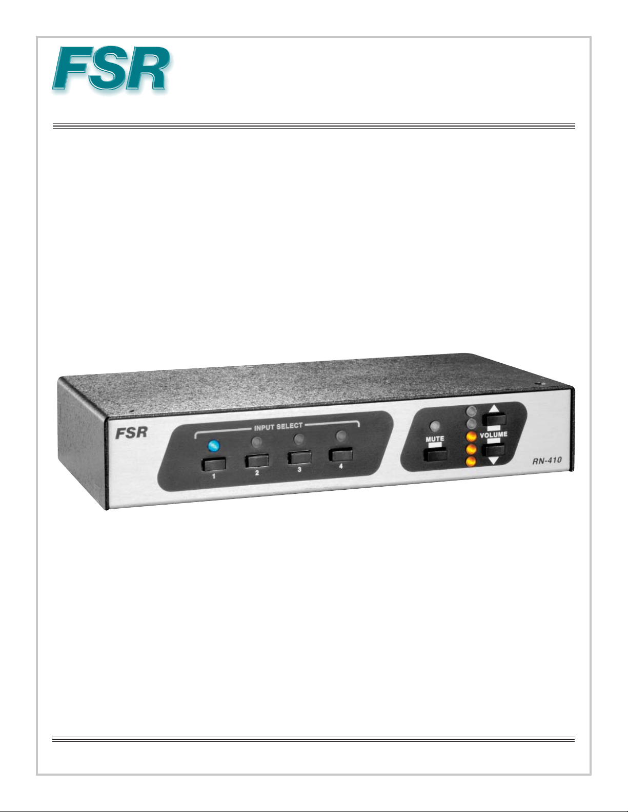
SOURCE SELECTION
The source video and audio input are selected by pressing one of the 4 source buttons located on the left side
of the front panel. A single lamp will be illuminated to indicate the selection. Note that the audio source input
may be separately confi gured to a source different from that of the video input via the RS-232 interface.
This is referred to as audio breakaway.
The audio breakaway feature, when confi gured, will result in the lamp of the current video source input selected
being lit continuously and the audio breakaway source will blink intermittently at a rate of once per second.
Pressing a source select button will return both audio and video to the selected source and terminate the audio
breakaway feature.
AUDIO LEVEL ADJUSTMENT
The audio output level may be adjusted via the up and down buttons located on the right side of the front panel.
The audio range may be adjusted in 1 dB increments from a fl oor of –45 dB to +5 dB by either pressing and
holding the Vol Up or Down button or by discrete button presses. Each discrete press adjusts audio in 1dB
steps. When continuously pressing a volume up or down button, the audio output level will be ramped in 1
dB increments, traversing the entire range from –45 to +5 dB in approximately 6 seconds. The 5 audio output
lamps are illuminated accordingly to refl ect 6 ranges (including all OFF).
Audio mute may be toggled on and off by pressing the Audio Mute button to the immediate left of the audio
output level lamps. The user may adjust the audio output volume down while remaining in mute state.
However, if the user presses the volume up button while muted then the audio will be unmuted and the audio
output level will be adjusted accordingly.
AUDIO TRIM ADJUSTMENTS
The audio trim may also be adjusted for each of the 4 audio sources via the front panel. This is done by fi rst
pressing and holding the desired audio source input button (thus switching both video and audio to that source)
and then simultaneously pressing the volume up or down buttons to adjust the trim for the selected source. Note
that the lamps will not be illuminated to refl ect the adjusted trim and will remain illuminated to refl ect the audio
output level as may have been adjusted as above. The audio trim may be ramped up or down by holding both
the audio source button and the respective trim direction button and will traverse the –5 dB to +15 dB range in
approximately 2-3 seconds. Or the user can adjust in discrete 1 dB increments by discrete volume up or down
presses. When the audio source button is released, the audio trim adjustment is terminated.
AUDIO CARD ABSENT
The RN-410 is also available in confi gurations without an audio card. These RN-410 models have video
capabilities only. However, the RN-410 chassis still contains the Volume lamps and buttons as well as the
4
Page 5

Audio Mute lamp and button but they are effectively disabled and the lamps will not be lit. This provides a
visual cue to user that the audio feature is absent on this model. The serial interface also provides indication of
whether audio capability is present or not (see RN-410 Serial Protocol Manual).
POWER UP / FAILURE OPERATION
The RN-410 is capable of detecting imminent power failures and stores any confi guration parameters to FLASH
memory before complete power failure in order to restore the most recent operating confi guration on start-up.
A 5 second delay period upon power up allows for the power to stabilize. The user should wait 5 seconds after
power up before operating or trying to send any serial commands to the unit.
DEFAULT FACTORY SETTINGS
The RN-410 can be returned to its default factory settings by fi rst pressing and holding the Audio Mute button
and then simultaneously pressing the Volume Up button. The default settings confi gure the default video and
audio output to port one, the audio output level to –30 dB and the audio trim levels for each audio input to 0 dB.
TYPICAL APPLICATIONS
5
Page 6

PINOUTS AND CABLING
Cable Type: Standard 4 pin S-Video to two
BNC male cable.
Maximum Recommended Length: 35 ft
Pinout
Please see the RN-410 serial protocol manual included with the product for serial
commands and other details on RS-232 control.
RS-232 HARDWARE CONFIGURATION
BAUD RATE 38400
DATA BITS 8
STOP BITS 1
PARITY NONE
FLOW CONTROL NONE
2
3
5
CABLE
Tx
Rx
G
RN-410
SERIAL
INPUT
TX
RX
GND
DB9M
2
3
5
CABLE
RN-410
SERIAL
INPUT
Rx
Tx
G
A/V
DEVICE
DB9F
(DCE)
RX
GND
2TX
3
5
Serial Control Port for Control of DCE
Devices
RX
TX
GND
PC or
A/V
DEVICE
DB9M
(DTE)
TX
GND
DB9F
2RX
3
5
Serial Control Port for Control of DTE
Devices
6
Page 7

RN-410 AUDIO INPUT CONNECTOR WIRING
FROM A STEREO UNBALANCED SOURCE
SHIELD
INSTALL JUMPER
(2) SHIELD
I
N
SIGNAL FLOW
P
U
T
L+ L- SH R+ R-
OPTIONAL JUMPER
FROM A STEREO BALANCED SOURCE
I
N
SIGNAL FLOW
P
U
T
L+ L- SH R+ R-
SHIELD
INSTALL JUMPERS
SHIELD
FROM A MONO UNBALANCED SOURCE
I
N
SIGNAL FLOW
P
U
T
L+ L- SH R+ R-
FROM A MONO BALANCED SOURCE
I
N
SIGNAL FLOW
P
U
T
L+ L- SH R+ R-
OPTIONAL JUMPER
COMMON
INSTALL JUMPER
RN-410 AUDIO OUTPUT CONNECTOR WIRING
TO A STEREO UNBALANCED
PREAMP INPUT
O
U
SIGNAL FLOW
T
P
U
T
L+ L- SH R+ R-
TO A STEREO BALANCED
PREAMP INPUT
O
U
SIGNAL FLOW
T
P
U
T
OPTIONAL JUMPER
INSTALL JUMPERS
COMMON
INSTALL JUMPER
TO A MONO UNBALANCED PREAMP INPUT
O
U
SIGNAL FLOW
T
P
U
T
L+ L- SH R+ R-
OPTIONAL JUMPER
TO A MONO BALANCED PREAMP INPUT
O
U
SIGNAL FLOW
T
P
U
SHIELD
T
(2) SHIELD
L+ L- SH R+ R-
L+ L- SH R+ R-
INSTALL JUMPER
7
Page 8

SPECIFICATIONS
VIDEO INPUT
MODEL RN-410YA RN-410CA RN-410P /PA RN-410SA
SIGNAL TYPE COMPONENT COMPOSITE RGB S-VIDEO
CONNECTOR
NUMBER/TYPE
IMPEDANCE 75 OHM
LEVEL 1 VOL T P/P
VSWR <1.1@250MHz <1.3@100MHz <1.1@250MHz <1.3@100MHz
ISOLATION >80dB@10MHz
DIFFERENTIAL
PHASE
DIFFERENTIAL
GAIN
VIDEO OUTPUT
MODEL RN-410Y A RN-410CA RN-410P /PA RN-410SA
SIGNAL TYPE COMPONENT COMPOSITE RGB S-VIDEO
CONNECTOR
NUMBER/TYPE
IMPEDANCE 75 OHM
GAIN UNITY INTO 75 OHMS
OFFSET 15mV MAX +/-4mV TYPICAL
BANDWIDTH 450 MHz 500 MHz 450MHz 500 MHz
FLATNESS +/-0.25dB 0 to
4X3 RCA FEMALE 4 BNC FEMALE 4 HD-15 FEMALE 4-4 PIN FEMALE
>65dB@100MHz
NA 0.05 degrees NA 0.05 degrees
NA 0.02% NA 0.02%
1X3 RCA FEMALE 1 BNC FEMALE 1 HD-15 FEMALE 1-4 PIN FEMALE
150MHz
+/-1dB 150 to 400
MHz
>80dB@10MHz
>63dB@100MHz
+/-15mV MAX
+/-.25dB to
100MHz
>80dB@10MHz
>65dB@100MHz
15mV MAX +/-4mV TYPICAL
+/-0.25dB 0 TO
150MHz
+/-1dB 150 TO 400
MHz
DIN
>80dB@10MHz
>63dB@100MHz
DIN
+/-15mV MAX
+/-.25dB to
100MHz
AUDIO
BANDWIDTH 20 Hz to 20 kHz (+/- 0.1dB)
THD+NOISE 0.1% @20 kHz at rated max output
NOISE FLOOR <-90dBu
CHANNEL SEPARATION <-85dB @ 1kHz
AUDIO INPUTS
SIGNAL TYPE 4 stereo balanced (may be used with unbalanced sources)
CONNECTOR NUMBER/
TYPE
IMPEDANCE 20k ohms balanced
TRIM RANGE -15dB to +5dB in 1dB steps
GAIN RANGE -45dB to +5dB in 1dB steps
5 pin pluggable screw terminal
AUDIO OUTPUT
NUMBER/TYPE 1 stereo balanced or unbalanced
CONNECTOR NUMBER/
TYPE
IMPEDANCE 50 ohms
MAXIMUM LEVEL 600 ohms: +12dBm balanced / +6dBm unbalanced
SYNC ( RN-410P /PA only)
INPUT IMPEDANCE 511 ohms
OUTPUT IMPEDANCE 75 ohms
INPUT LEVEL TTL 2.0 V minimum
OUTPUT LEVEL 5 V into HI-Z / 2.4 V into 75 ohms
OUTPUT RISE AND FALL TIME 1nS
PROPAGATION DELAY 16nS
One 5 pin pluggable screw terminal
HI-Z: +14dBm balanced / +8dBm unbalanced
RS-232 HARDWARE CONFIGURATION
BAUD RATE 38400
DATA BITS 8
STOP BITS 1
PARITY NONE
FLOW CONTROL NONE
POWER AND PHYSICAL
POWER 9 VAC @500mA power supply
included or 12VDC @ 300mA
CONNECTOR TYPE 2 pin pluggable screw terminals
MOUNTING Standard 19” rack mount included
SHIPPING WEIGHT 3 lbs.
8
Page 9

WARRANTY AND RETURN INFO
WARRANTY POLICY
This product is warranted against failures due to defective parts or faulty workmanship for a period of one year
after delivery to the original owner. During this period, FSR will make any necessary repairs or replace the unit
without charge for parts or labor. Shipping charges to the factory or repair station must be prepaid by the owner,
return-shipping charges, via UPS / FedEx ground, will be paid by FSR.
This warranty applies only to the original owner and is not transferable. In addition, it does not apply to repairs
done by other than the FSR factory or Authorized Repair Stations.
This warranty shall be cancelable by FSR at its sole discretion if the unit has been
subjected to physical abuse or has been modifi ed in any way without written authorization from FSR. FSR’s
liability under this warranty is limited to repair or replacement of the defective unit.
FSR will not be responsible for incidental or consequential damages resulting from the use or misuse of
its products. Some states do not allow the exclusion of incidental or consequential damages, so the above
limitations may not apply to you. This warranty gives you specifi c legal rights, and you may also have other
rights which vary from state to state.
Warranty claims should be accompanied by a copy of the original purchase invoice
showing the purchase date (if a Warranty Registration Card was mailed in at the time of purchase, this is not
necessary). Before returning any equipment for repair, please read the important information on service below.
SERVICE AND RETURN AUTHORIZA TION
Before returning any equipment for repair, please be sure that it is adequately packed and cushioned against
damage in shipment, and that it is insured. We suggest that you save the original packaging and use it to ship the
product for servicing. Also, please enclose a note giving your name, address, phone number and a description of
the problem.
NOTE: All equipment being returned for repair must have a Return Authorization (RMA) Number. To
get a RMA Number, please call FSR Service Department (973-785-4347).
Please display your RMA Number prominently on the front of all packages.
CONTACT INFORMATION
FSR Inc.
244 Bergen Boulevard,
West Paterson, NJ 07424
Tel: (973) 785-4347 · Fax: (973) 785-4207
E-Mail: sales@fsrinc.com · Web: http://www.fsrinc.com
9
Page 10

10
 Loading...