

Page 1

P T B - 2 / 3 / 4
PTB Series
Pop – Up Table Boxes
INSTALLATION MANUAL
PROPRIETARY INFORMATION
All information in this manual is proprietary to and the property of FSR inc.
This publication is protected by the Federal Copyright Law, with all rights reserved.
No part of this document may be reproduced, transcribed, or transmitted,
in any form or by any means, without prior explicit written permission from FSR inc.
244 Bergen Boulevard, West Paterson, NJ 07424 Tel 973.785.4347 Fax 973.785.4207
E-Mail sales@fsrinc.com • Web www.fsrinc.com
FSR PTB Installation Manual [Page 1 of 6]
Page 2
FSR PTB SERIES POP-UP TABLE BOXES
Installation and Operating Instructions
The PTB series “Pop Up” Table Boxes provide a roomy interior space as well as
the ability to retract, flush to the tabletop, when not in use. Access by the user is effortless
via a simple “push-push” activation. The flush mounting provides a flat working surface
when the unit is closed and not in use. Solid construction and ease of installation make this
durable table box a compliment to any conference room or office environment.
Initial Setup and Preparation
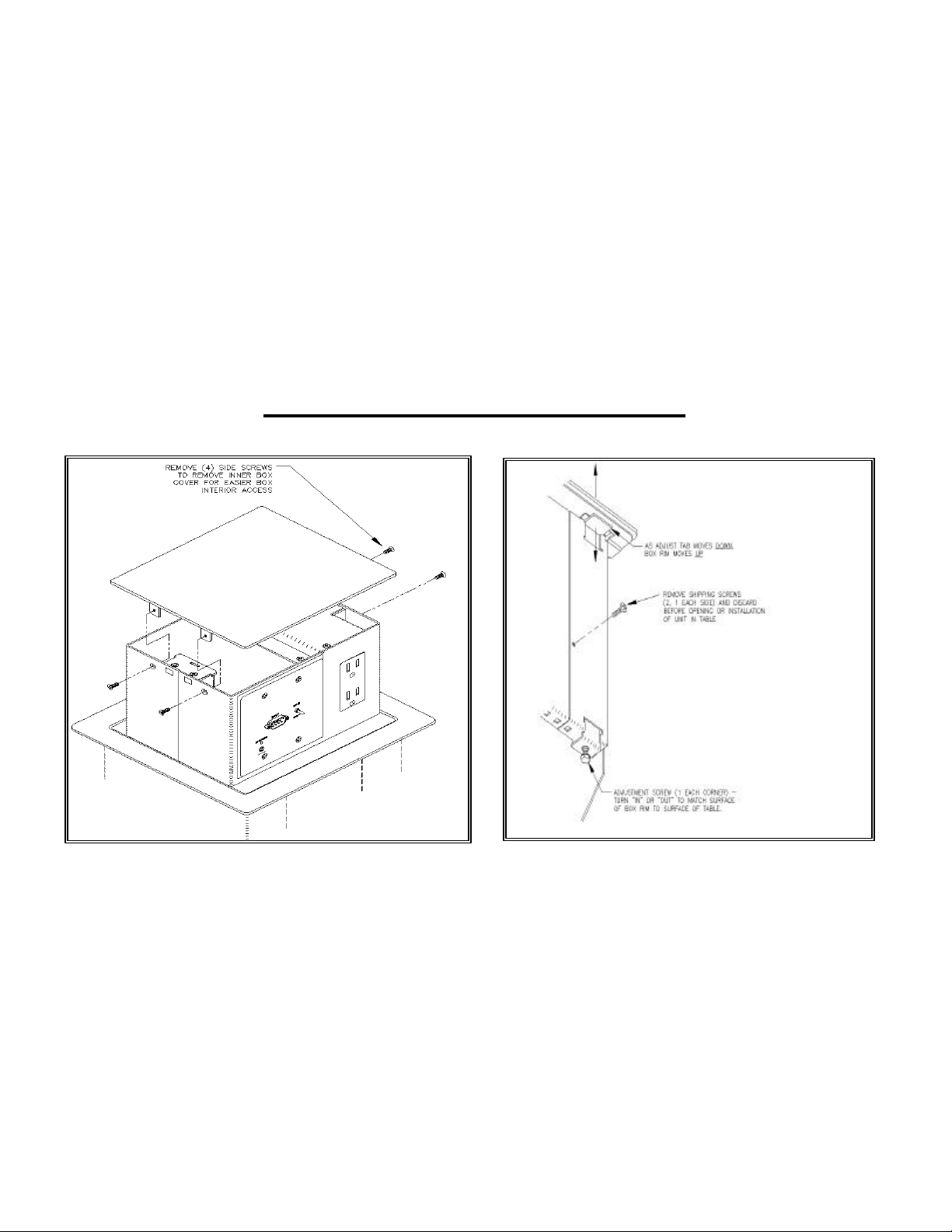
The PTB is mounted from the top of the table as shown in Fig. 1
A drawing (Fig. 6) is provided for cutting the opening and routing the “rabbet” on the table.
Consideration should be given to placement and position to ensure the most functional
orientation and user convenience.
The open PTB should be placed on a protective pad as close as possible to the table
opening for ease of wiring.
FSR PTB Installation Manual [Page 2 of 6]
Page 3

Remove the shipping screws (2) completely and store in a safe place (Fig. 2).
Push down on tabletop box to release and access the connector panel. (Fig 1). The
connector panel chassis will automatically ascend from the outer assembly and expose the
connector plate openings for wiring and mounting the connector plates (not supplied). This
customer-supplied plate must not contain high voltage. This space is designed for CLASS
2 devices only.
Remove the inner box cover side screws (4) (Fig. 1) to allow access to the PTB interior for
wiring.
Cabling is inserted through the cut opening from the bottom of the table and into interior of
the table box. There is a separate compartment with a duplex outlet for 117 VAC service
entry ONLY. Be certain to isolate high and low voltage cabling per local electrical codes.
Allow enough slack in the cable runs to ensure free and full travel of the box while opening
and closing. Use tie-wraps as shown in Fig. 4 to limit strain and pinching. Open and close
the box to confirm adequate clearance.
PTB Mounting Procedure
The PTB series table thickness range is from ¾” to 4”. Adjustments are provided to
accommodate a wide range of table thickness.
Insert the PTB into the table opening and push the housing into the rabbet until the top and
surrounding rim are inside the rabbet. Adjust the four rim height adjustment screws (Fig. 2)
to 1/64” above the table surface. (Final tightening of the locking clamps will pull the table in
later steps)
FSR PTB Installation Manual [Page 3 of 6]
Page 4

The inner box cover, to outer rim height adjustment screws are factory set and should not
require any adjustment. If adjustment does become necessary, loosen the two lock screws
(Fig 3) and turn the adjusting screw to raise and lower the surface of the inner box cover
with respect to the surface of the rim. Retighten the two lock screws (Fig. 3) to secure the
adjustment position.
After height adjustments are completed install and tighten the locking clamps (2) as shown
in Fig. 5 to lock the PTB into place.
There is a factory installed duplex outlet provided for local 117 VAC power at the PTB
faceplate. The 8’ AC cord can be plugged into a 117 VAC outlet close to the PTB housing.
The PTB’s power cord is the main-disconnect device. The power socket / outlet should be
installed near the table box and should be easily accessible. The PTB’s are designed to
operate in a maximum recommended ambient temperature (TMRA)
of 45° C (113° F).
FSR PTB Installation Manual [Page 4 of 6]
Page 5

FSR PTB Installation Manual [Page 5 of 6]
Page 6

WARRANTY POLICY
This product is warranted against failures due to defective parts or faulty workmanship for a
period of one year after delivery to the original owner. During this period, FSR will make
any necessary repairs or replace the unit without charge for parts or labor. Shipping
charges to the factory or repair station must be prepaid by the owner, return-shipping
charges, via UPS / FedEx ground, will be paid by FSR.
This warranty applies only to the original owner and is not transferable. In addition, it does
not apply to repairs done by other than the FSR factory or Authorized Repair Stations.
This warranty shall be cancelable by FSR at its sole discretion if the unit has been
subjected to physical abuse or has been modified in any way without written authorization
from FSR. FSR’s liability under this warranty is limited to repair or replacement of the
defective unit.
FSR will not be responsible for incidental or consequential damages resulting from the use
or misuse of its products. Some states do not allow the exclusion of incidental or
consequential damages, so the above limitations may not apply to you. This warranty gives
you specific legal rights, and you may also have other rights which vary from state to state.
Warranty claims should be accompanied by a copy of the original purchase invoice
showing the purchase date (if a Warranty Registration Card was mailed in at the time of
purchase, this is not necessary). Before returning any equipment for repair, please read the
important information on service below.
SERVICE
Before returning any equipment for repair, please be sure that it is adequately packed and
cushioned against damage in shipment, and that it is insured. We suggest that you save
the original packaging and use it to ship the product for servicing. Also, please enclose a
note giving your name, address, phone number and a description of the problem.
NOTE: all equipment being returned for repair must have a Return authorization (RMA) Number. To
get a RMA Number, please call the FSR Service Department (973-785-4347). Please display your RMA
Number prominently on the front of all packages.
CONTACT INFORMATION
244 Bergen Blvd.
West Paterson, NJ 07424
Phone: (973) 785-4347 *Order Desk Fax: (973) 785-4207
E-mail: sales@fsrinc.com Web Site: http://www.fsrinc.com
FSR PTB Installation Manual [Page 6 of 6]
 Loading...