

Page 1
INSTALLATION AND OPERATOR’S MANUAL
SYSTEM MAP
MIX
C
MIX
A
MIX
SALON II SALON IV
D
MIX
B
MIX
SALON III
E
MIX
G
MIX
MIX
SALON V SALON VII
F
H
MIX
I
SALON VISALON I
MIX
J
MIX
K
SALON VIII
. 5 4
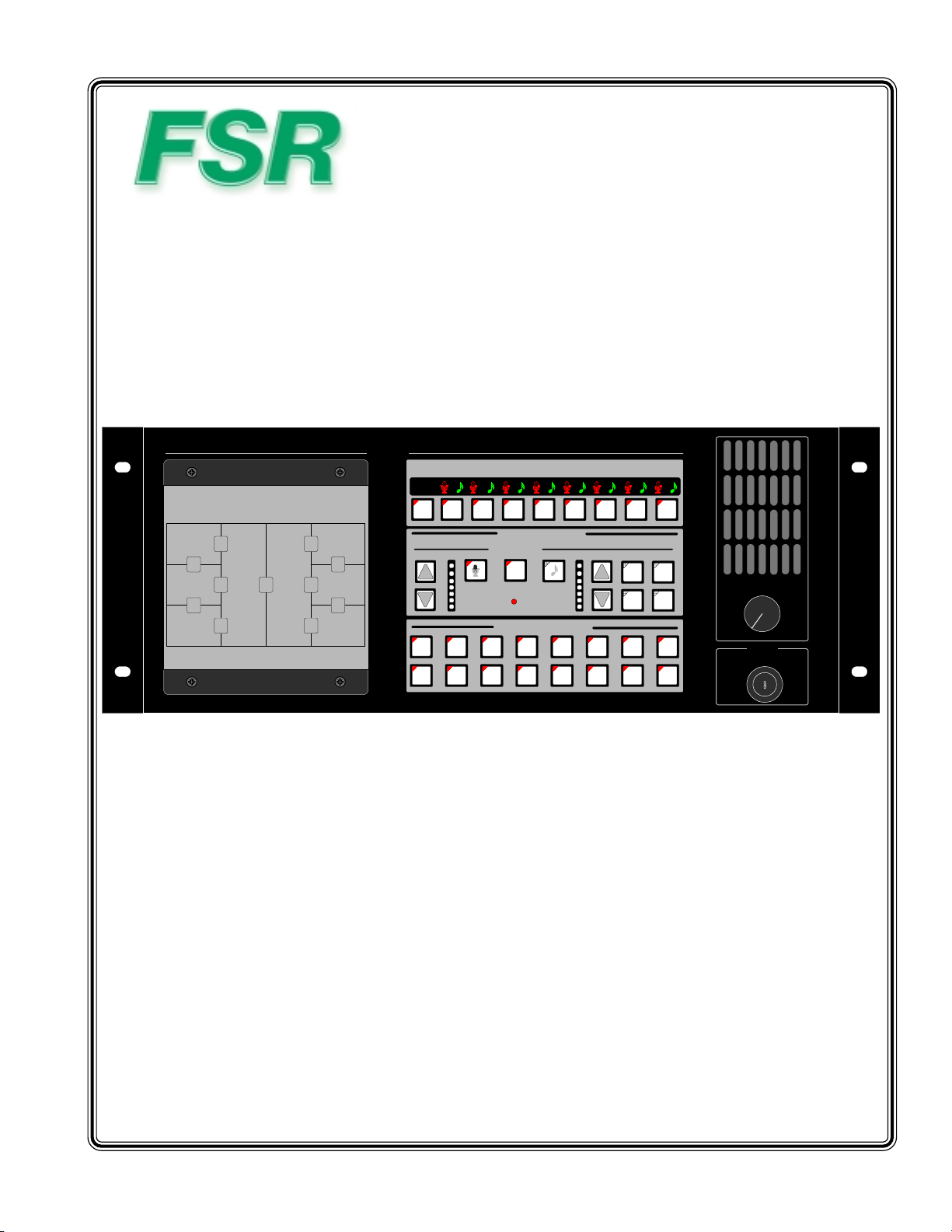
ML-800
ROOM CONTROL SELECT AND STATUS INDICATORS
LMLMLMLMLMLMLML
OFF
O 1 2 3 4 5 6 7 8
SPEECH AUDIO
ON/OFF ON/OFF
VOLUME
2
2
ROOM CONTROL
LOCAL
MIXER
L
M
ROOM COMBINED
BACKGROUND MUSIC
VOLUME
2
1
2
3
SOURCE
MIX SWITCH SELECT
A B C D E F G H
I J K L M N O P
M
2
4
MONITOR VOLUME
MIN MAX
PANEL
INTE R LOC K
Model ML - 800
8 ROOM AUDIO CONTROL SYSTEM
244 Bergen Boulevard, West Paterson, NJ 07424 • Tel 9737854347 • Fax 9737853318 • Web www.fsrinc.com
12/02 LIT1011
Page 2

PROPRIETARY INFORMATION
All information in this manual is proprietary to and the property of FSR inc.
This publication is protected by the Federal Copyright Law, with all
rights reserved. No part of this document may be reproduced, transcribed, or
transmitted, in any form or by any means, without prior explicit
written permission from FSR inc.
2 ML-800
Page 3

Operators Safety Summary
The general safety information in this summary is for operating personnel.
Do Not Remove Covers or P anelsThere are no user-serviceable parts within the unit. Remov al of the top cover will expose dangerous voltages. To
avoid personal injury , do not remo v e the top cover. Do not operate the unit without the cover installed
Power SourceThis product is intended to oper ate from a po wer source that will not apply more than 230 volts rms between the supply conductors or
between both supply conductor and ground. A protective ground connection b y w ay of grounding conductor in the power cord is essential for safe
operation.
Grounding the Product This product is grounded through the grounding conductor of the po w er cord. To avoid electrical shock, plug the power cord
into a properly wired receptacle before connecting to the product input or output terminals.
conductor in the power cord is essential for safe operation.
A protective-ground connection b y w a y of the g rounding
Use the Proper Power Cord Use only the power cord and connector specified for your product. Use only a power cord that is in good condition. Refer
cord and connector changes to qualified service personnel.
Use the Proper FuseTo avoid fire hazard, use only the fuse having identical type, voltage rating, and current rating characteristics. Refer fuse
replacement to qualified service personnel.
Do Not Operate in Explosive AtmospheresT o a v oid e xplosion, do not operate this product in an e xplosiv e atmosphere.
Terms In This Manual
.
WARNING
personnel. NOTE Highlights an essential operating procedure, condition or statement.
CAUTION
and maintenance (servicing) instructions in the literatureaccompanying the appliance.
AVERTISSEMENT!Le point d´exclamation dans un triangle equilatéral signale à alerter l´utilisateur qu´il y a des instructions d´operation et d´entretien
tres importantes dans la litérature qui accompagne l´appareil.
VORSICHTein Ausrufungszeichen innerhalb eines gleichwink eligen Dreiecks dient dazu,den Benutz er auf wichtige Bedienungs-und
Wartungsanweisungen in der Dem Great beiliegenden Literatur aufmerksam zu machen.
WARNING
be connected to an accessible outlet near the unit. Building Branch Circuit Protection: For 115 V use 20 A, for 230 V use 8 A.
WARNING
227 and IEC-245 standards. This cord will be fitted with a tandem prong-type plug.
Highlights an operating procedure, practice, condition, statement, etc., which, if not strictly observed, could result in injury to or death of
The exclamation point,or lighting bolt, within an equilateral triangle is intended to alert the user to the presence of important operating
The rear panel ON/OFF switch does not disconnect the unit from input AC power. To facilitate disconnection of AC pow er, the power cord must
When the COMPASS is used in the 230-volt mode, a UL listed line cord rated for 250 volts at 15 amps must be used and must conform to IEC-
Terms As Marked on Equipment
CAUTION
of personnel.
CAUTION
and maintenance (servicing) instructions in the literatureaccompanying the appliance.
AVERTISSEMENT!
d´entretien tres importantes dans la litérature qui accompagne l´appareil
Highlights an operating procedure, practice, condition, statement, etc., which, if not strictly observed, could result in injury to or death
The exclamation point, or lighting bolt, within an equilateral triangle is intended to alert the user to the presence of important operating
Le point d´exclamation dans un triangle equilatéral signale à alerter l´utilisateur qu´il y a des instructions d´operation et
VORSICHT
Wartungsanweisungen in der Dem Great beiliegenden Literatur aufmerksam zu machen.
NOTE
are designed to provide reasonable protection against harmful interference when the equipment is operated in a commercial environment. This equipment
generates, uses, and can radiate radio frequency energy and, if not installed and used in accordance with the instruction manual, may cause harmful
interference to radio communications. Operation of this equipment in a residential area is likely to cause harmful interference, in which case the user will
be required to correct the interference at the users own expense.
Ein Ausrufungszeichen innerhalb eines gleichwinkeligen Dreiecks dient dazu, den Benutzer auf wichtige Bedienungs-und
This equipment has been tested and found to comply with the limits for a Class A digital device , pursuant to Part 15 of the FCC Rules. These limits
ML-800 3
Page 4

Contents
CHAPTER ONE ........................................................................................................... 5
INTRODUCTION ................................................................................................................................. 6
UNPACKING ....................................................................................................................................... 7
ML-800 COMPONENTS ................................................................................................................... 10
EQUIPMENT PLACEMENT ............................................................................................................ 11
GROUNDING .................................................................................................................................... 12
CHAPTER TWO......................................................................................................... 11
ML-800 SYSTEM CONFIGURATION ............................................................................................ 12
ML-800 SYSTEM BLOCK DIAGRAM ............................................................................................ 13
ML-800 SYSTEM COMPONENTS .................................................................................................. 14
CHAPTER THREE.................................................................................................21
SYSTEM SPECIFICATIONS ............................................................................................................ 22
AUDIO CONNECTOR WIRING ...................................................................................................... 25
CABLING........................................................................................................................................... 26
DIP SWITCH / JUMPER SETTINGS ............................................................................................... 28
ADJUSTMENTS ................................................................................................................................ 33
CHAPTER FOUR ...................................................................................................... 35
PAGING SYSTEM OPERATION ..................................................................................................... 36
FACILITY MANAGER OPERATION............................................................................................37
CHAPTER FIVE ....................................................................................................... 39
MULTIPLE ACUs .............................................................................................................................. 40
REMOTE MAP AND MONITOR PANELS ..................................................................................... 42
SOUND SYSTEM/LIGHTING CONTROL SYSTEM INTEGRATION ......................................... 43
MAP PANEL STATUS INTERFACE ML-116-INT ....................................................................... 44
4 ML-800
Page 5

CHAPTER ONE
What you will find in this chapter…
• Introduction
• Unpacking Data
1
• System Components
• Equipment Placement
• Grounding Considerations
ML-800 5
Page 6

INTRODUCTION
The design of the ML-800 system takes advantage of current technology to provide a blend of reliability,
ease of use, flexibility, and reasonable cost. Designed for Hotels and Conference Centers with divisible,
multi-use meeting rooms, the ML-800 unifies the audio system of each room being joined together with
the touch of a button. Each control panel, speaker, amp, etc. will automatically operate as one sound
system. Any number of rooms (up to 16 per system) can be combined in any number of groups. The
custom software, which is provided, allows the system to be tailored to specific system requirements.
The ML-800 eliminates the need for skilled operators and can be used by staff members with minimum
instruction. The combining can be controlled from multiple locations depending on the system options,
and specific functions can be controlled from each room. The quality of the sound system is not compromised by this system. Built-in safeguards prevent system failure due to misuse or failure of one
component.
A typical ML-800 system may include:
o ML-800 RACK Audio Control Unit
o PSA Power Supply
o Wallplates User selectable; 2 gang/3gang membrane or touch control (optional)
o FMP Facility Manager Panel Interface (optional)
o AUD Remote Audio Monitoring (optional)
o RMAP Remote Map Panel (optional)
o RMON Remote Monitor Panel (optional)
o CNTL Control System Interface (optonal)
o INT Map Panel Status Interface (optonal)
o LU Lutron® Lighting Interface (optonal)
o IM Installation Manual
In each room a wallplate controls music and local input functions (local input on/off, room mixer enable,
music select, and volume up/down switches for local input and music.) A bar graph display is provided
for local input and music.
The security key switch or access code on the touch panel prevents unauthorized control of the system.
Dip switches inside the Audio Control Unit determine whether the key switch or code interlocks all the
wallplate functions, microphone functions only, or no wallplate functions.
The system is shipped in a default setting which will permit instant operation of the system in its usual
configuration. Please refer to the Dip switch/Jumper settings for pertinent details on the switch functions.
6 ML-800
Page 7

UNPACKING
Your ML-800 system should contain the following components;
• ML-800RACK (audio control unit) This is the rack unit with the Map/Monitor Panel
• ML-PSA ( large power supply)
• If Wall Plates were ordered Room control panels, one for each room in the system. Depending on the
order either 2 or 3 gang membrane wallplates or touch wallplates will be shipped.
On some installations two wallplates may be required per room.
• If the Facility Manager Panel was ordered you should have an FM-INT Interface Unit, the
RS-232 interconnect cable, a 3.5" diskette, and a power supply. (*)
• If the Remote Audio feed was ordered you should have an enclosed audio speaker along
with special relay cards (116-MNRL and 116-MNP) mounted on a 19 inch
TRAC-BRAC. (*)
• If the Remote Map Panel was ordered you should have the R-MAP Panel with its power
supply.
• If the Remote Monitor Panel was ordered you should have the R-MON Panel which will
mount on top of the R-MAP Panel.
• If the Lutron lighting interface was ordered then you should have the ML-116-INT & power
supply unit.
• This installation Manual.
(*) With multiple ML-800 systems with the FMP or AUX option(s) some duplicate
components are not provided. Please consult factory.
ML-800 7
Page 8
ML-800 SYSTEM COMPONENTS
ML-800RACK
FRONT VIEW
map of the facility
installs in this space
REAR VIEW
page control input
P=priority
N=normal
G=ground
remove this card to set
jumper switches
future use
to FM INT for computer
control via FM-Panel software
8 ML-800
Page 9
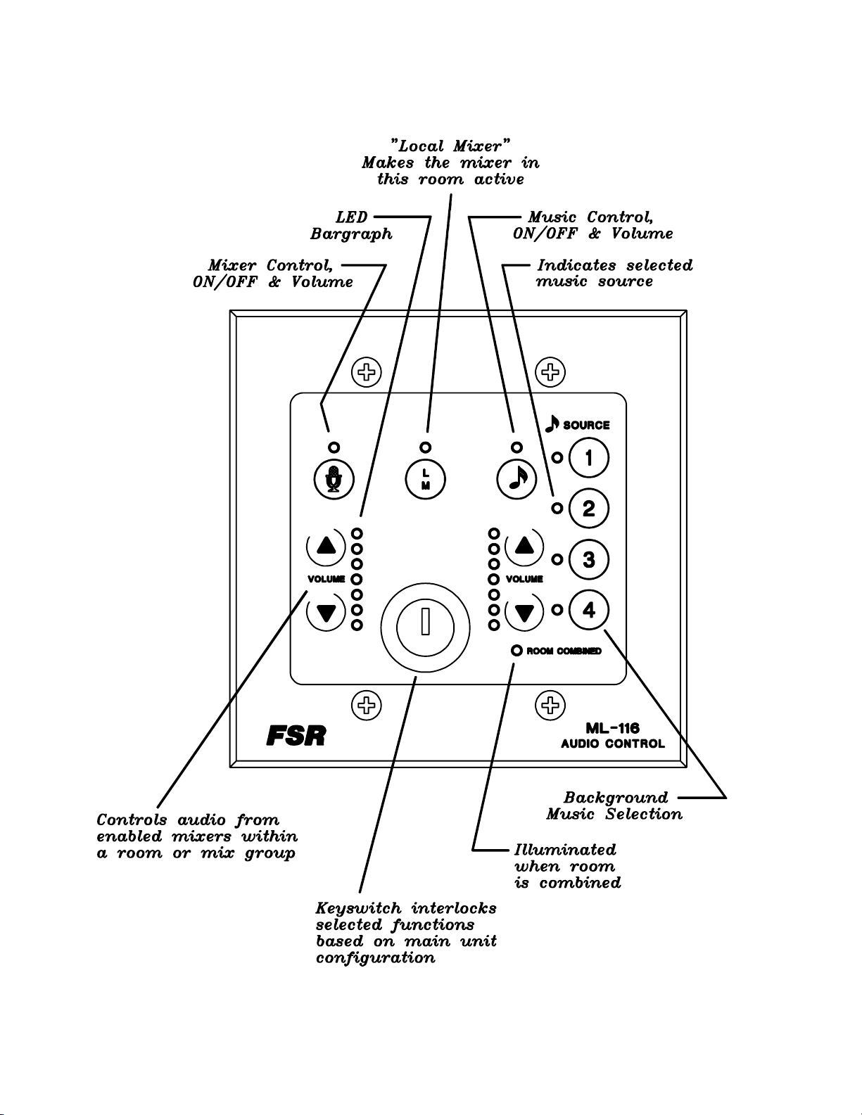
ML-800 WALLPLATE (optional) 2 Gang shown (also available in 3 gang)
MEMBRANE TYPE
ML-800 9
Page 10
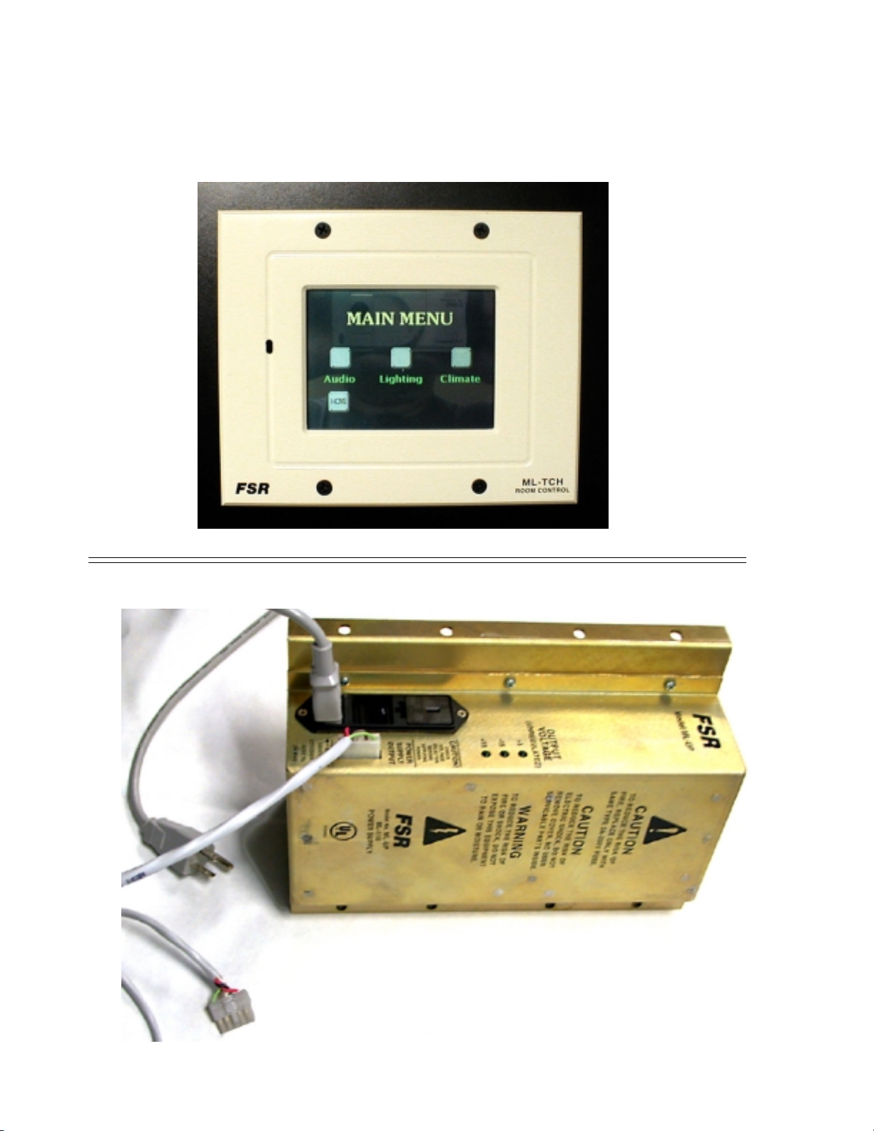
ML - 800 TOUCH WALLPLATE (optional)
ML - 800 POWER SUPPLY PSA
10 ML-800
Page 11

EQUIPMENT PLACEMENT
The ML-800RACK is mounted first. It should go in the audio rack at eye level usually 55 inches from
the finished floor.
The ML-PSA is mounted in the same rack as the ACU. It mounts in the rear of the rack usually at
waist level.
When the Facility Managers software, with audio monitoring (ML-116-AUD), is ordered then another TRAC-BRAC with a ML-116-MNRL & MNP is also installed at the rear of the rack. This
completes the rack mounting of the ML-116 components.
The wallplates are mounted next. At least one wallplate is mounted in each room. In larger rooms
two wallplates may be required. The membrane wallplates mount in a standard 2 gang/3 gang electrical box (min. depth 3 inches) and are connected to the cable already pulled. The touch wallplate
mounts directly in its own enclosure. Refer to the section on wallplates to determine proper hook-up.
If the Facility Managers software with audio monitoring (ML-116-AUD) was ordered then the
enclosed audio speaker, as well as the FM-INT small desk top mounted box, are located in the
Managers Office.
If the Remote Map and/or Monitor Panel was ordered then this unit will be mounted, most likely, in a
service corridor and will wired back to the ML-800RACK.
If the Lutron lighting interface was ordered then the ML-116-INT unit would be mounted in the
lighting dimmer rack location
ML-800 11
Page 12

GROUNDING
It is strongly recommended that in any rack setup to ensure appropriate power application as
well as superior power surge protection that the FSR Power Conditioning and Sequencing (SPC)
System be utilized.
The ML-800 System, along with the associated mixers, equalizers, and power amplifiers, is a high gain
audio system of some complexity and requires a proper grounding procedure be followed.
The ML-800 equipment has separate audio, digital, and chassis grounds. The digital and audio grounds
come together in the unit. Inside the ML-800RACK on the regulator card there is a ground (chassis)
terminal that is tied to analog ground through a removable jumper. In most installations there is no need
to touch this jumper.
WALLPLATE GROUNDING CONSIDERATIONS
In order to prevent damage to the ML-800 system from ESD (Electro-Static Discharge), it is incumbent upon the installer to carefully consider the grounding of the system. Since the ML-800 is a
digital/audio hybrid, proper ground is essential to maintaining audio quality while preventing damage
the electronic circuitry.
The metal faceplate of the ML membrane wallplates (not the touch wallplates) must be grounded to
prevent damage due to ESD events. The best way to guard against ESD damage in any system is to
return the charge to ground by the shortest path possible. A direct connection between the faceplate
and conduit ground is the most desirable method. At the same time, the DC ground of the system
must be kept isolated from conduit ground, or ground loop noise will result.
The ML membrane wallplates are provided with either a ground wire or a ground jumper to allow for
grounding of the metal faceplate. If the electrical mounting boxes are already grounded, the ground
wire must be insulated or the jumper disconnected to prevent a ground loop. If the electrical box is
not grounded, connect the ground wire to the SHIELD terminal of wallplates so equipped. On
wallplates that have a ground jumper, ensure that the jumper is installed. In systems that do not have
grounded electrical boxes, the ESD ground path is through the shield conductor of the recommended
cable, through the ML-800’s connectors, and to the chassis of ML-800 rack unit.
The touch wallplate has a plastic enclosure and mounts in non-grounded back boxes so the ESD
ground path is through the shield conductor of the recommended cable, through the ML-800’s connectors, and to the chassis of ML-800 rack unit.
12 ML-800
Page 13

CHAPTER TWO
What you will find in this chapter…
• System Configuraton
2
• System Block Diagram
• System Components
ML - 800 11
Page 14

ML-800 SYSTEM CONFIGURATION
The ML-800 system allows the user greater flexibility than any other room combining system made
today! No other system allows the user the choice of 4 music input selections, or provides the local
mixer enable that greatly reduces distortion when combining rooms.
The basic system configuration consists of the ML-800 RACK which contains the Map / Monitor Panel,
Wallplates, either membrane or touch, and an optional Facility Manager’s Panel. Each unit of the ML800 has its own unique responsibility and processing is distributed throughout the entire system. The
responsibilities of each unit is described below:
ML-800 RACK
The ML-800RACK is the main controller of the system. It contains the CPU module, local audio,
power supply regulation, a MP (music page input) module.
The internal CPU module is responsible for controlling the other modules and receives data on what to
do from the Wallplates, Monitor / Map Panel and/or FM (Facility Manager) Panel. It uses dip switches
(discussed in the Dip switch/Jumper section) to determine settings and operating modes.
WALLPLATES
The wallplates are microprocessor controlled modules that are used for room audio control. They are
responsible for setting Local Input on/off, Music on/off, Music Selection, Local Input Volume, Music
Volume, and Local Mixer Enable on/off. The Section on Dip Switches describes the settings used on
the wallplates and those on the CPU module that set modes on the wallplates.
MAP / MONITOR PANEL & REMOTE MAP PANEL
The Map Panel is responsible for controlling the system setup by mixing rooms together. It is
microcontroller based and communicates to the CPU module in the ML-800RACK.
The monitor section, is also microprocessor controlled which allows the user to ‘monitor’ the settings in
a room. The user can adjust those settings by using the Map panel’s built in ‘wallplate’.
FACILITY MANAGER’S SOFTWARE PANEL, including the FM-INT Unit
This is a software program that runs on a PC and controls the system by replicating ML-800RACK
functions and status indicators and has the ability to combine rooms without mix switches. It is customized and is not configurable. It communicates over two twisted pairs to the ACU using a multidrop
proprietary protocol. The FM-INT Unit interfaces this line to the computer. An enclosed audio speaker
would also be used if the audio feed option was implemented.
12 ML - 800
Page 15

ML - 800 SYSTEM BLOCK DIAGRAM
SYSTEM BLOCK DIAGRAM
ROOM 1's AMPROOM 1's MIXE R
ROOM 2's AMPROOM 2's MIXE R
ROOM 3's AMPROOM 3's MIXE R
D
Interface Box
A
ROOM 5's MIXE R
BMG SOURCE 1
BMG SOURCE 2
BMG SOURCE 3
BMG SOURCE 4
TELEPHO N E
PAGE
CONTACT FROM PHONE SYSTEM
OR USE FSR ETA MODULE
AUDIO
REQUIRED
B
ML-800
BALLROO M
COMBINING
SYSTEM
ROOM 4's AMPROOM 4's MIXE R
ROOM 5's AMP
ROOM 6's AMPROOM 6's MIXE R
ROOM 7's AMPROOM 7's MIXE R
ROOM 8's AMPROOM 8's MIXE R
C
Remote MAP and
Monitor
HOME RUN or
DAISY CHAIN
WALL PLATES
A.........There will be two types of wallplates available for use in the ML-800 system; membrane and LCD. Both control
all wallplate functions. These functions include Music Selection, Room Mixer Enable, Music Enable and Volume, and
Local Input On/Off and Volume. Each room in the system can have two wallplates if desired.
B.........The ML-800RACK (audio control unit) is the main unit of the system. It routes the selected music, adjusts levels,
combines rooms, handles communications (between wallplates, touch map/ monitor panel), and can talk to other ML’s. It
also permits the operation of any wallplate function from this same panel as well as controlling the paging function.
The Monitor function (located in the ML-800RACK) permits an operator to monitor the audio from any selected room.
These two remaining items are described and shown further on in this document.
C....... This is the R-MAP and R-MONITOR unit that repeats the data on the rack map panel
D...... This is the ML-116-INT unit to handle the lighting interface
ML - 800 13
Page 16

OVERALL VIEW OF SYSTEM COMPONENTS
MAP/MONITOR PANEL
SYSTEM MAP
MIX
C
MIX
A
MIX
SALON II SALON IV
D
MIX
B
MIX
SALON III
E
MIX
G
MIX
MIX
SALON V SALON VII
F
H
MIX
I
SALON VISALON I
MIX
J
MIX
K
SALON VIII
. 5 4
ROOM CONTROL SELECT AND STATUS INDICATORS
LMLMLMLMLMLMLML
OFF
O 1 2 3 4 5 6 7 8
SPEECH AUDIO
VOLUME
2
2
A B C D E F G H
I J K L M N O P
ROOM CONTROL
LOCAL
MIXER
ON/OFF ON/OFF
L
M
ROOM COMBINED
MIX SWITCH SELECT
BACKGROUND MUSIC
VOLUME
2
2
ML-800
M
SOURCE
1
2
3
4
MONI T O R V O L U ME
MIN MAX
PANEL
INT E R LO C K
MAP/Monitor Panel Operation
The MAP/Monitor Panel acts as a master control point. It will display the Facility layout
map graphic user interface and provide full room control and adjustment. It will also
display room status and audio levels by emulating individual wallplate functions and status
indicators.
To combine (mix) rooms:
Touch each MIX SWITCH SELECT to configure the grouping you wish to combine. That switch
will illuminate to indicate those two rooms are combined. For example by operating switch A, Salons
one and two will be combined.
To break up a combined group:
Touch the switch corresponding to that mix. The Led will extinguish
To call up a wallplate for control or status:
Operate the desired switch in the ROOM CONTROL SELECT AND STATUS INDICATORS area
and then the ROOM CONTROL section of the panel will contol that room. It will be as if you were
standing at the actual wallplate. Audio will be active at the local speaker at this time and the ‘listen
in” feature is enabled. Simply make the desired adjustments via touch
14 ML - 800
Page 17

ML - 800 TOUCH WALLPLATE (optional)
ML - 800 15
Page 18

ML-800 WALLPLATE (optional) 2 Gang (also available in 3 gang)
MEMBRANE TYPE
16 ML - 800
Page 19

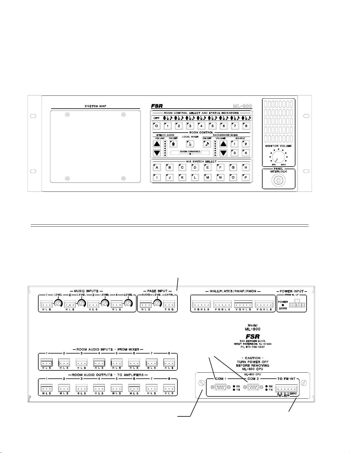
REAR OF ML-800RACK UNIT
CD
E
F
G
A
B
This is the main unit of the system. It routes the selected music, adjusts levels, combines rooms, handles
communication (between wallplates, map, and monitor panels), and can route audio to other ML-800s.
I
H
It also controls the paging function.
Refer to above Figure for the following discussion.
A...These 3 pin connectors receives the audio signal from the room's mixer.
B...These 3 pin connectors provides the audio output to the room's amplfier or EQ.
C...These four 3 pin connectors receive the background music signals from the facility supplied sources.
The source number over each connector corresponds to the identification called out on the MAP panel
as well as the room wallplates.
D...This trim control provides limited volume adjustment for each background music source.
E...This 3 pin connector accepts the page audio signal from the facilities page audio feed. A level adjust
is provided for this input. The three pin connector to the right of the level adjust is the control input for
paging. The choices are Normal or Priority, determined by an external switch.
F...Wallplate/monitor interface connectors. These four points are where all room wallplates are con-
nected. The remote map/monitor and the ML-116-INT interface unit are connected to one of these
points. Four points are provided to ease system installation.
G...The ML-800 regulator module accepts unregulated DC voltages from the ML-800 PSA, power
supply. A plugable connection is provided to connect to the power supply. A LED indicator is provided
to monitor the power within the unit.
H...Facility managers panel interface connector. Refer to section on this topic for additional details.
I....These two COM ports are for future use.
ML - 800 17
Page 20

CHAPTER THREE
What you will find in this chapter…
• System Specifications
• Audio Connector Wiring
3
• Cabling
• Dip Switch / Jumper Settings
• Adjustments
ML - 800 21
Page 21

SYSTEM SPECIFICATIONS
Audio
Frequency Response: 20 Hz – 20 kHz +/- .5 dB
THD: .03% @ 1kHz with MAX Rated Input Level
MAX Input level: +18 dBm
Noise Floor: -90 dBm
Conditions: Mixer Enables ON, Local Inputs ON, Nothing mixed, Inputs Open, Outputs
600 ohm terminated, Volume set to 0 dB
Volume preset: -6 dB
Crosstalk: -95 dB @ 1kHz, -78 dB @10 kHz Any Input to Any Output
Mic + Music Volume
Control Range: +10 dB to – 11 dB (Volume range adjustable from In-room controls)
Room Audio Inputs
Number and Type: 8 mono balanced
Connector used: 3 pin Phoenix
Impedance: 20k ohm
MAX Input Level: +18 dBm
Input Gain: 0 dB and +10 dB gain, dip switch selectable (SW 16 on CPU card)
Background Music Inputs
Number and Type: 4 mono balanced
Connector used: 3 pin Phoenix
Impedance: 20k ohm
MAX Input Level: +18 dBm
Trim level Adjust Range: -6 dB to +20dB
Paging Input
Number: 1 mono balanced
Connector used: 3 pin Phoenix
Impedance: 20k ohm
MAX Input Level: +18 dBm
Trim level Adjust Range: -6 dB to +20dB
Type: All Page with two priority levels; normal (n) and priority (p)
Output
Number and Type: 8 mono balanced
Connector: 3 pin Phoenix
Impedance: 50 ohms
MAX Level: +22 dBm into 600 ohms load
Power Input Ratings
100 /120 / 220 /240 VAC 50 /60 Hz Max 2A.
Expansion Ports
2 nine pin sub-D com ports for future use
Size
4 RU 19L x 7H x 11.5D inches Standard rack mounting with supplied rack ears.
A vailable Accessories
Membrane Wall Plate
Color Touch Wall Plate
AMX / Crestron Interface
Facility Manager Package
22 ML - 800
Page 22

Wall Plates
Membrane
Size: 6 1/4 inches wide by 4 1/2 inches high, approximately 2.5 inches deep
Mounting: fits standard 2 or 3 gang electrical wall box with four or 6 screws
Switches: membrane
Connector: 5 pin connector
Cable: West Penn #3651 or 3751 (see page 27 for details)
Touch
Size: 6 1/4 inches wide by 4 1/2 inches high, approximately 2.5 inches deep
Mounting: back box supplied
Switches: touch panel
Connector: 5 pin connector
Cable: West Penn #3651 or 3751 (see page 27 for details)
Power Supply (PSA)
Size: 3 1/2 inch high, 6 inches deep, 10 inches long (approximately)
Mounting: rear rack rail
Input power: 105 to 132 VAC, 50/60 Hz, 100 watts
Output: +15 volts, +25 volts, -25 volts nominal
Fuse: 2 amp
Switch: power on/off (lighted rocker switch)
Interconnect: 8 foot cable supplied, 5 conductor stranded
Indicators: three LED indicators, one for each of the unregulated voltages
FM Facility Manager Control (optional)
Facility Managers Panel (FM-INT)
Size: an enclosed box 3 1/2 inches wide, 5 inches long, 1 1/2 inches high
Mounting: sits on the managers desk
Power: a wall mounted power supply
AUD Audio Monitor Add-on (optional)
Size: processor card(MNP); 3 1/4 inches wide, 7inches long, 1 1/2 inches high
speaker switching card (MNRL); 3 1/4 inches wide, 9 1/2 inches long, 1 1/2
inches high
Mounting: both the MNP and the MNRL cards come already mounted in a 19 inch FSR
TRAC-BRAC
Speaker: enclosed in an attractive baffle 7 inches high, 6 1/2 inches wide, 5 inches deep
R-MAP Remote Map Panel (optional)
Size: 20" wide, 14" high, 2 1/8" deep
Mounting: standard rack rails
Power: 120 VAC, via knockouts in case
ML - 800 23
Page 23

R-MON Remote Monitor Panel (optional)
Size: 20" wide, 5 1/4" high, 2 1/8" deep
Mounting: standard rack rails
Power: 120 VAC, via knockouts in case
CTRL Control System Interface (optional)
Size: 8 1/2", 1 1/2" high, 4 3/4" deep
Mounting: use supplied rack mounting bracket
Power: wall wart 9 VAC
INT Map Panel Status Interface (optional) & LU Lighting Interface (optional)
Size: 7 1/2" wide, 7 1/2" high, 2 1/2" deep
Mounting: panel mount
Power: wall wart 9 VAC
24 ML - 800
Page 24

Page 25

AUDIO CONNECTOR WIRING
In any professional sound system with many inputs and outputs it is strongly recommended that all
audio wiring be balanced. All the audio inputs and outputs on the ML-800 system are balanced.
alanced configuration the connectors are wired as follows:
In a b
HIGH
LOW
SHIELD
SOURCE
HIGH
LOW
SHIELD
OUTPUT
EVICE
D
If due to some equipment limitations unbalanced wiring must be used then the proper way to wire the
audio connectors follows:
Input Wiring (single wire with overal shield)
HIGH
LOW
SHIELD
HIGH
LOW
SHIELD
INSTALL JUMPER HERE (SEE OPPOSITE PAGE)
Input Wiring ( two conductor overal shield)
Output Wiring (single w
ire with overal shield)
SOURCE
SOURCE
HIGH
LOW
HIGH
LO
SHIELD
Output Wiring (
two conductor with overal shield)
OUTPUT
D
OUTPUT
DEVICE
EVICE
ML - 800 25
Page 26

CABLING
AUDIO
All audio connections to the ACU are 3 pin connectors with pin 1 shield, pin 2 High, and pin 3 Low.
CONTROL WIRING
The following diagram illustrates the control wiring for the ML-800 system. Refer to following
sections for details on facility manager operational hookup.
Audio input p lates
P ro v id ed b y o th e rs
HOME RUN
4 Background
Music Inputs and
System Page
BMG
SOURCE 1
Room 1
MIXER
Room 2
MIXER
Room 8
MIXER
EACH
WALL PLATE
BMG
SOURCE 2
BMG
SOURCE 3
BMG
SOURCE 4
PHONE
PAGE
Room 1
AM P
M L-800
COMBINING SYSTEM
Room 2
AM P
OR
DAISY CHAIN
UP TO 6
WALL PLATES
Room 8
AM P
26 ML - 800
Page 27

WALLPLATES
The wallplates can be wired in either a home run (star) or modified daisy chain configuration.
Use two twisted pair 22 AWG stranded, with an overall shield (West Penn # 3651) if the home run
configuration is employed for each wallplate and total distance to any wallplate does not exceed 1000
feet.
Use two twisted pair 18 AWG stranded, with an overall shield (West Penn #3751) if the wallplates are
daisy chained together (it is recommended to only daisy chain 6 wallplates per home run) with no more
than 1000' total wire length.
Refer to the figure for terminal identification. Five screw terminals are provided on the rear of the
wallplate for cable hook-up. While the Membrane wallplate is depicted all connections are identical on
the Touch wallplate.
REAR OF WALLPLA TE
Note: it is essential that in any case the voltage
on pin 1 on the wallplate connector be in excess of 8
volts DC.
TERMINAL POSITION
1 POWER 8VDC min
2 POWER GND
(THIS IS ONE PAIR)
3 DATA HIGH
4 DATA LOW
(THIS IS ONE PAIR)
5 SHIELD IF USED
One is installed in each room and is wired to the ML-800RACK. The wallplates mount in a standard 2
or 3 gang electrical box. An eight position dip switch on the rear of the wallplate is used to assign the
wallplate's room address. This switch is preset at the factory to the area identified on the back of the
wallplate itself, but should be checked prior to installation.
The system is shipped in a default setting for all dip switches which will permit instant operation of the
system in its usual configuration. Please refer to the DIP SWITCH section for details on all the dip
switch functions.
ML - 800 27
Page 28

DIP SWITCH / JUMPER SETTINGS
ACU Audio Control Unit, CPU Module
The CPU PC board contains sixteen (16) dip switches which will allow users to customize the system to
a large degree. These switches allow the user to select such options as simultaneous microphone and
music operation, key switch or touch panel interlock functions, ramp speed, etc. The definition of the
switches are as follows:
Dip switch Factory Setting Explanation
1 open Memory Volume
2 open Preset Volume
3 open Reserved
4 open Enable Mode
5 open [Wall Plate
6 open Interlock Mode]
7 open Reserved
8 closed Cold Start Select
9 open Select multiple Systems
10 open Select multiple Systems
11 open Select multiple Systems
12 open Select multiple Systems
13 open Enable/disable security code lockout
14 open If Monitor Panel Present
15 open If FMP present
16 open Room audio input level
Dip switch 1 - Initial Volume Memory Option - closed the volume is determined by the dipswitch
2 setting, if open the volume is restored to level that was last set.
Dip switch 2 - Preset Volume - Setting determines the power up default volume level, if closed
the volume initializes to -12 db, if open it initializes to 0 db.
Dip switch 3 - Reserved
Dip switch 4 - This dip switch allows simultaneous operation of voice and music. If the dip
switch is open then the system is in normal mode, the voice and music are exclusive. This is com-
monly referred to as the pre-enable mode. If the dip switch is closed, both voice and music can be
operated at the same time (simultaneous mode). The system is shipped with this dip switch in the
open position.
28 ML - 800
Page 29

Dip switch 5 and 6 - Wallplate Interlock Mode.
If Switch 5 is closed, the wallplate keyswitch has no effect on the operation of the wallplate. The local
input and music sections of the wallplate are always active. In this position Switch 6 is not used.
If Switch 5 is open and Switch 6 is open, the ‘partial interlock’ mode is selected. This is the default
mode for the ML-116. In this mode, the keyswitch interlocks only the microphone section of the
wallplate.
If Switch 5 is open and Switch 6 is closed, the ‘full interlock’ mode is selected. In this mode, the
wallplate cannot be operated without the keyswitch.
Dip switch 7 - Reserved
Dip switch 8 - System Clear When system power is removed the ML-800 has the capability to
save the state of the system including the combining status of all the rooms and the state of each room’s
local input and music selectors and volume. If open, the System saves its states, if closed it initializes to
a “clear” state. System is shipped with this switch closed.
Dip switches 9 to 12 are used to address multiple ML-800’s. The coding is as follows:
12 11 10 9 ML-800 12 11 10 9 ML-800
O O O O - 1 C O O O - 9
O O O C - 2 C O O C - 10
O O C O - 3 C O C O - 11
O O C C - 4 C O C C - 12
O C O O - 5 C C O O - 13
O C O C - 6 C C O C - 14
O C C O - 7 C C C O - 15
O C C C - 8 C C C C - 16
Note: C=dip switch is closed, O= dip switch is open
These switches would only be used with a Facility Managers Panel and multiple ML-800 systems.
Dip Switch 13 - Reserved
Dip Switch 14 - Reserved
Dip Switch 15 - Reserved
Dip Switch 16 - Room audio input level. Unity gain switch open, +10dB gain switch closed
ML - 800 29
Page 30

WALLPLATES (optional)
The wallplates used in the ML-800 system are either membrane or touch. They control all wallplate
functions. These functions include Music Selection, Local Mixer, Music Enable and Volume, and Mi-
crophone Enable and Volume.
When the wallplates sense a key press or touch, it waits for a poll from the ML-800 RACK then it sends
a message to the ACU which will return an update message. The wallplates will then check for another
touch or keypress and repeat. Internal flags will prevent the wallplates from acting on the same keypress
or touch until the update message is returned. This whole process occurs within a fraction of a second.
The wallplates communicate with the ML-800RACK over a RS-422 line and are addressable. This
address is a 5 bit address (0-31) allowing the use of up to two (2) wallplates per room.
30 ML - 800
Page 31

Membrane Wallplate Dip Switch Settings
The ML-800 allows for up to 16 wallplates: 2 per room up to 8 rooms. The wallplates must be
individually addressed. The addresses are set by setting the dip switches on the back of the wallplate.
The address is a binary code representing the room number minus one, given on switches 1 through 4
with a closure representing a 1.
SWITCH 1 2 3 4
ROOM 1 0 0 0 0
.
ROOM 2 1 0 0 0
ROOM 3 0 1 0 0
Note: 0= switch open
ROOM 4 1 1 0 0
1= switch closed
ROOM 5 0 0 1 0
ROOM 6 1 0 1 0
ROOM 7 0 1 1 0
ROOM 8 1 1 1 0
Switch 5 is used for rooms with two wallplates. In a two wallplate room, one and only one of the
wallplates (it does not matter which one) should have switch five closed.
Switches 6 through 8 are used for factory self tests and should be open for normal use.
SWITCH POSITIONS
1-5 ADDRESS
6-8 FACTORY USE ONLY
Picture of rear of wallplate
ML - 800 31
Page 32

Wall Plate Functions
All wallplates will handle these functions in the same way.
Speech/Audio
Alternating action switch that enables/disables audio from any selected mixers within a mixed group.
“Pre-selects” audio from any selected mixers in a mixed group when music is playing.
Local Mixer
Alternating action switch that enables/disables audio from the mixer associated with a given area to be
heard in the entire mixed group. The switch remains independent of the corresponding switch on other
panels within a mixed group. This switch tracks with local input in a single room and will automatically
turn on in the first room in a mixed group to enable local input.
Music
Alternating action switch that activates selected music source within each room or a mixed group of
rooms.
Music Select 1-4
Selects the music source within each room or a mixed group of rooms.
Up/Down Volume (Speech)
Ramps volume up/down within each room or a mixed group of rooms. Associated bar graph indicates
level and is active only when local input is audible. All bar graphs within a mixed group will track
together.
Up/Down Volume (Music)
Ramps volume up/down within each room or a mixed group of rooms. Associated bar graph indicates
level and is active only when Music is enabled. All bar graphs within a mixed group track together.
Keyswitch
Interlocks (disables) certain groups of switches on the wall plate as determined by the selected option
jumpers.
32 ML - 800
Page 33

ADJUSTMENTS
As with any high performance audio system, proper adjustment is key to achieving optimum S/
N (signal to noise) ratio and performance characteristics.
Once the system is fully assembled including the mixers, amplifiers and other audio processing equipment, you may begin.
In order to properly calibrate the system, you will need a signal source capable of providing a mic and
line level signal. You will also need a VTVM or other instrument that can measure voltages, preferably
with a dBm scale.
Begin by injecting a 1 Khz. typical mic level signal into a mic input of the Room One mixer. Monitor the
output of the mixer using the VTVM while adjusting the mixer channel and main out controls to achieve
a 0 dBm level. The mixer controls should not be set to their extreme settings for best performance. Mark
the settings so that users may re-establish them after changes are made. Continue by moving the input
signal to each of the mixers mic input channels, and calibrating them in turn.
CAUTION: At no time in the following procedure should you change levels by adjusting the
volume up down switches at the Wallplates or ML-800 Monitor Panel. Doing so will invalidate
your calibrations resulting in a lot of wasted time.
If you should accidently alter the volume settings, reset the system to a known state by turning
the power off and on, and reselecting the desired settings.
Next , using the ML-800RACK or Room Control Panel, set Room One to Local Mixer on, Mics On.
The Mic volume bar graph should illuminate the third led from the top. If not, consult the dip switch
setting section of this manual to reset the factory settings. Check the output level of Room One to
confirm unity gain through the ML-800 system. Proceed to the output of each successive audio component in Room One’s audio chain, adjusting as necessary to achieve 0 dBm. Stop at the power amplifier
input.
Move the signal source to the first mic input of the next mixer, and repeat the procedure for Room Two.
Continue in this manner until all rooms are complete.
BACKGROUND MUSIC SET-UP
Continue by setting Room One’s wallplate to Music On, Mic and Local Mixer Off. Select music source
one. The Music volume bar graph should illuminate the third led from the top. Inject the anticipated
nominal music level into Music Input Source 1. Adjust the associated gain trim pot ( just below the input
connector) to yield 0 dBm at the ML-800 audio output connector. Select the next music source and
repeat this procedure until all four outputs are calibrated.
If the paging feature of the system is to be used, inject the anticipated level page signal into the page
input connector. Connect the P (priority page) terminal to ground on the page control terminal block
Adjust the page gain trim pot to obtain 0 dBm at the output of the ML-800 audio card.
ML - 800 33
Page 34

At this point, the entire system is calibrated, with the exception of the power amplifier gain setting. To
set the power amplifier gain, you will require some equipment to measure SPL in the room area. Begin
by mixing all room areas together, and opening all divisible meeting areas. If your system consists of
several nonmixable subsections, mix all rooms that are possible.
Set all area wallplates to Music On, Mic Off. Inject the anticipated level signal into the Music Source
One input bus. Using the SPL measuring instrument, monitor each room and adjust each power amplifier as necessary to achieve a uniform level throughout all areas.
Keep in mind that the ML-800 system will allow volume adjustment of +10dB to -11dB with respect to
unity, so you will want to adjust the amps close to the maximum desired level during this procedure.
The adjustment procedure is now complete.
34 ML - 800
Page 35

CHAPTER FOUR
What you will find in this chapter…
4
• Paging Operation
• Facility Manager Operation
ML - 800 35
Page 36

PAGING SYSTEM OPERATION
The Room Combining System supports the integration of a new or existing paging system. A
Page Audio input, and Nor mal/Priority mode page selects are provided for interface to the
system.
The actual paging operation of a particular system will depend upon how paging was implemented by the audio system design engineer/installing contractor.
The system supports two primary paging modes; Normal Paging and Priority P aging. During
a Priority mode page, the room audio will be muted and the page audio will be unconditionally switched into the rooms, regardless of room wallplate settings. The page audio level is
controlled only by the pre-configured amplifier gain settings, and page input level adjust control on the ML-800RACK. Any selected audio ( Mics and/or Music playing in the selected
rooms) will be disabled for the dur ation of the page.
ing Priority mode paging to guard against interrupting any meetings in progress.
Normal mode page, Normal paging will occur during music operation, but will be automati-
cally disabled if Mic audio is enabled in the selected room. During a Normal page, page audio
will be mixed with any selected audio in the room ( Music only, based on factory settings). The
page audio level is controlled only by the pre-configured amplifier gain settings, and page
input lev el adjust control on the ML-800RACK. As with the Priority mode paging, page volume
level does not depend upon wallplate volume settings.
Caution should be used when select-
Users are encouraged to consult with their installing contractor to configure the Room
Combining System paging options so as to optimize the operation of a particular
installation.
To initiate paging, select the desired paging mode (pr iority or normal) and speak into the
microphone. To end paging, release the page mode push button.
Typical Hookup Diagram
MIKE
MIXER
PRIORITY
NORMAL
GROUND
36 ML - 800
Page 37

FACILITY MANAGERS PANEL
The Facility Managers Panel (FMP) is a Windows based program that performs all the same functions as the Map Panel
and adds additional capability. The most important of which is the ability to mix nonadjacent rooms. The display of
the FMP is a bit mapped image of what the Map Panel looks (or would look) like . It can take the place of the Map Panel and
can perform the functions of the wallplates.
When the FMP starts it requests status from the ACU. The ACU responds with group information if any. The ACU will
update the group information if a Map Panel is present and has defined a group. The FMP uses the group information to
update the Windows display to reflect those rooms that have been selected into groups.
FMP Installation
To install the FMP a cable is run from the Room Combining System ACU to the manager's office. This cable is two twisted
pairs with an overall shield and they connect to the CPU module at the ACU. In the managers office the cable terminates in
the FM-INT unit which in turn plugs into com port 1 or 2. If the audio option was ordered then another cable, specifically a
standard audio line (one twisted pair with an overall shield) would also be run. It connects from the left-most terminals on
the Monitor Relay Card and terminates in the speaker enclosure mounted in the manager's office.
Hookup Diagram Overview (refer next page for detailed hookup)
These two items are
located in the
managers office
to any Windows
compatible computer
audio line
connects here
These are interconnected
partial view of the
Relay card (116MNRL)
partial view of the
CPU module (rear
of ML-800 rack)
Partial view
of small
micro board
mounted on
TRACBRAC with
Relay card
self contained speaker
with volume control
(supplied)
ML - 800 37
Page 38

Group Functions
The FMP group functions include defining groups, adding rooms to groups, and removing groups. These functions are
similar to the Map Panel except that instead of using the Interlock switch and push button the user uses a mouse.
Groups are defined as rooms that are combined to become a larger room. The rooms in the group share the same levels,
music selection, and other settings. A significant advantage when using the FMP is the ability to combine nonadjacent
rooms.
Rules applicable to the combining of rooms
The default wallplate settings for all the rooms in a group follow four levels of precedence:
1. If a microphone is active (local input on) that has highest pr iority.
2. If a microphone is selected but not yet active (local input selected) that is the next priority.
3. If music is active that is the next lower priority.
4. If nothing is selected that is the lowest prior ity.
Combining rooms rely on a set of possibilities and priorities. The possible combinations are combining a single room to a
single room, adding a single room to a group, and combining two groups. The priorities in descending order are Local
Input On, Pre-enable On, Music On, and Nothing On. When combining two single rooms the settings in each room is
checked against the priorities and the room with a lower priority setting takes on the settings of the other room. When
combining two groups the group with the lower priority takes on the settings of the group with the higher priority. When
combining rooms or groups of equal priority, the room volume is reset to the default level as determined by dipswitch 2.
Some other rules applicable to the grouping of rooms are:
•Any group that cannot be directly represented on the Map panel cannot be affected (mixed or u n -
mixed) by the Map panel.
•Wallplate volume level changes affect only the rooms in the group on that ACU.
•All Local Mixers switched on the non-originator units will be locked off.
Wallplate Status
The user has the ability to review the settings of a wallplate in any room. The user will double click on the room which
causes the FMP to request the data from the ACU. The user will then be able to view and hear (if remote audio monitor was
ordered) the selections on the wallplate.
38 ML - 800
Page 39

CHAPTER FIVE
What you will find in this chapter…
• Multiple ACU's
5
• Remote Map and Monitor Panels
• Audio / Lighting Systems Intergration
• Map Panel Status Interface
ML - 800 39
Page 40

MULTIPLE ACUs
In order to control more than 16 rooms the Room Combining System has the ability to create groups
that overlap ACUs. The ACU has a TieLine Bus which will, depending on switch settings, allow the
unit to send to, or receive output from a room not present on that unit. This feature is an option and
available only on systems with a FMP (Facility Managers Panel).
The user who wishes to combine multiple Room Combining Systems would have to assign the groups
on each ACU (Audio Control Unit). The user selects the room to be used as the source, then the room
on the other unit to be considered the destination. The output from the source will be sent via the
TieLine to the destination room. The FMP will send update messages to both ACUs and will automati-
cally configure the wallplates effected by the TieLine. Wallplates on the destination room will be set to
mics on, music off to enable the use of the TieLine.
The example illustrated on the next page shows the FMP connected to 2 ACUs. The object is to define
a group containing ACU#1 Rooms 1 and 2 plus ACU#2 Rooms 1 and 2. The FMP would send a Group
message to both ACUs listing ACU#1 Room 1 first making it the source room, then ACU#1 Room 2,
then ACU#2 Room 1 making it the destination room, and finally ACU#2 Room 2.
The source room is the room that feeds the TieLine. The destination room uses the TieLine for input.
There can be only one source which means that if there was an ACU#3 added to this group ACU#2
would use Room 1 as the source for ACU#3 and so on. The first Room listed on ACU#3 would become
the destination as well as the source if an ACU#4 were added.
Jumpers on the ML-800 CPU are set for multiple units. For more information please consult the factory.
40 ML - 800
Page 41

Diagram illustrating multiple ACUs
ML-800 RACK #1
ML-800 RACK #2
HOST COMPUTER
To wallmount transformer
(supplied)
ML - 800 41
Page 42

REMOTE MAP AND MONITOR PANELS
R-MAP and R-MONITOR
This accessory permits full operation of the Room Combining System from a location other than the
rack area. Typically it would be mounted in a service corridor near the rooms of interest. Usually both
the map and monitor panel are used however the unit will operate without the monitor panel if cost is
a major consideration.
42 ML - 800
Page 43

SOUND SYSTEM/LIGHTING CONTROL SYSTEM INTEGRATION
Now it is possible to have the lighting follow the audio output Mix Lamp Status from the ML-800
room combining system. The addition of the ML-116-LU option interfaces LUTRON® lighting to the
ML-800 room combining system permitting lighting to follow audio using one integrated wallplate.
The ML-116-LU option for the ML-800 system consists of a ML-116-INT unit and a special
wallplate designed to fit in a four gang plastic trim kit provided by LUTRON®. This four gang kit
mounts 1 LUTRON® controller and 1 FSR wallplate. The ML-116-INT unit receives RS-485 serial
data from the ML-116 system,
processes it and opto-couples electronic closures to properly operate the LUTRON® lighting
system. The data transmitted consists of mix switch status and head table status.
INSTALLATION
Equipment Areas
The sound system and lighting control system for the meeting rooms/ballroom shall be coordinated at the wallstation and via the sound system’s room combining control.
The integration of the lighting control system to the sound system combining panel, FSR model
number ‘ACU’, shall be via contact closures. The integration shall allow the lighting controls to be
combined/separated based on the status of the partitions on the ML-800RACK panel, which is providing the same function for the audio controls.
The electrical contractor shall be responsible for the mounting of the ML-116-INT interface unit
and wiring to the lighting control system. The sound contractor shall be responsible for the wiring
between the ML-116-INT, and the ML-800RACK panel as well as the system setup to ensure proper
operation. Usually there will be a LUTRON® representative present to review the entire lighting
system and will also check on this phase of the installation.
Room Wallplates
Each room in the ballroom area has a control panel that fits in a standard 4 gang electrical box.
The wallstation model number shall be ML-116/LU4S. The control is comprised of three components:
1. The ‘ML-116-LUWP’ control plate provided by FSR.
2. The ‘-4S’ lighting control provided by Lutron.
3. The ‘ML116/4S-FP’ screwless faceplate provided by Lutron.
Equipment - Room Combining Control Interface
The integration of the lighting control system to the sound system combining panel, FSR model
number ‘ACU’, shall be via contact closures, Lutron model number ‘GRX-AV’ or ‘FSR-CIP’ as the
project requires. The integration shall allow the lighting controls to be combined/separated based on
the status of the partitions on the ‘ACU’ panel, which is providing the same function for the audio
controls.
ML - 800 43
Page 44

The electrical contractor shall be responsible for the mounting of the ‘GRX-AV’ or ‘FSR-CIP’
interface and wiring to the lighting control system. The sound contractor shall be responsible for the
wiring between the Lutron interface, the ML-116-INT, and the ‘ACU’ panel as well as the system
setup to ensure proper operation.
MAP PANEL STATUS INTERFACE ML-116-INT
An ML-116-INT unit can output 32 mix switch or head table switch outputs. If both mix and head
table information is required then then additional units can be added. The serial data from the ML-116
system would just loop thru each unit.
The ML-116-INT unit has an indicator LED for each corresponding wire terminal. These terminals
denote either room combinations or head table positions. The inclusion of a LED for each terminal
provides a rapid and accurate way to determine the operational status of both the ML-116 and the
LUTRON lighting equipment.
A drawing of the ballrooms/meeting rooms is provided with each system. This drawing indicates
the room mix switches and head table locations (via a numbering system) as they correspond to the
appropriate terminal positions on the ML-116-INT. If multiple ML-116-INT units are required for either the mix or head table functions then the map drawing would indicate that and provide for it in the
numbering system.
The actual unit is 7.5" long by 6" wide by 2" high, excluding the mounting ears each of the four of
which are 1.5" wide by 0.5" long. The unit weighs approximately 3 lbs. It is located in the lighting
equipment bay, not in the audio equipment area.
The ML-116-INT is supplied with a UL listed wall mounted transformer to power the unit.
It does not matter if the ML-116-INT is powered before or after the ML-116 Audio Control Unit.
The ACU periodically scans for all line devices.
Ground To ML-116 Remote Indicator
LO Connector
HI
Power Supply Connection no polarity
Control signals outputs
44 ML - 800
 Loading...