

Page 1

ML-500
Room Combining System
Operation & Installation
Manual
FSFS
FS
FSFS
244 Bergen Boulevard, W est Paterson NJ 07424 T e l 973-785-4347 Fax 973-785-3318
E-Mail sales@fsrinc.com W eb www .fsrinc.com
RR
R
RR
43828
Page 2

Page 3
ML-500
FSFS
FS
FSFS
AUDIO PRODUCT GROUP
244 Bergen Boulevard, West Paterson, NJ 07424 Tel 973-785-4347 Fax 973-785-3318 E-Mail fsr!sales@attmail.com
RR
R
RR
inin
in
inin
cc
c
cc
..
.
..
OPERATION and INSTALLATION
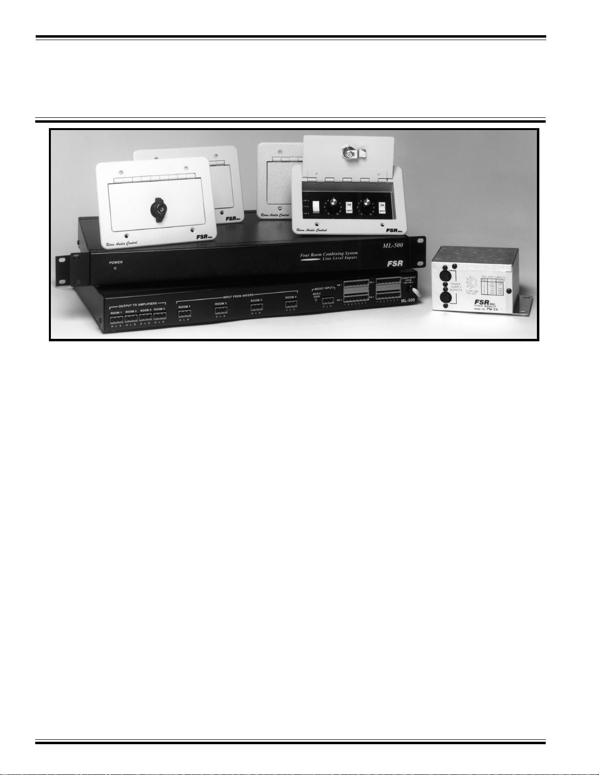
THE ML-500 ROOM AUDIO
COMBINING SYSTEM
Ideal for smaller hotels and conference centers with
more stringent budget restraints, the ML-500 strikes a
good balance in the basic requirements of microphone and
music control and the more elaborate features found in
our larger combining systems.
The system features in-room control plates to operate
microphone (on or off), background music (on or off), a
combine switch that can select one of two tielines or local,
and a volume control for the mic and music audio levels.
Efficient and fool proof installation is assured. The in-room,
3-gang wallplates have a 7-wire cable that connects via a
pluggable screw connector to the main control unit, and
power for the main unit is provided by a PM-2 power
supply .
System operation is easily understood and can be controlled by the staff.
T o combine two rooms, place each room’s combining
switch to Tieline A. The rooms are now mixed. For
background music set the music volume control on each
room's wallplate to the same value, and select "music on"
in both rooms. Music will be heard in both rooms equally
loud. The other two rooms could be combined by placing
each room combining switch to Tieline B.
If microphone operation is desired, the rooms could be
mixed as above, the microphone switch turned on in all
mixed rooms (two in this example), and then set the volume control equally in both rooms, for a the desired listening level.
If none of the rooms are combined, then each room’s
combining switch must be set on local. This allows
full control of each room’s audio from the wallplate.
All mixer inputs as well as the music input are electronically balanced. All audio outputs are balanced,
600 ohm, transformer-coupled outputs insuring
trouble-free installation.
There are two busses: Line A and Line B. Any
wallplate that selects either of these busses will have
its associated audio summed with any other wallplate
that selects the same line. Since this is a four-room
system (or less), only two busses are required to mix
rooms in any conceivable fashion.
INNOVATIVE ENGINEERING AND QUALITY MANUFACTURING OF ELECTRONIC SWITCHING AND CONTROL PRODUCTS
Page 4

FF
SS
RR
inin
cc
F
S
SS
R
RR
FF
Whenever rooms are combined, the volume controls in those rooms should be set at the same level.
Note that the music audio can be summed with the microphone audio anytime the microphone switch and
the music switch are in the on position.
The wallplates fully control the system; however, the wallplates receive no audio signals. This design permits the
main unit to be placed with the rest of the audio equipment, again simplifying installation and servicing.
A “QUICK SETUP GUIDE” has been provided to simplify day-to-day operation. Please instruct the user on
the proper use of the ML-500 with the use of this guide.
in
inin
c
cc
..
.
..
AUDIO PRODUCT GROUP
ML-500 INST ALLA TION DA T A
The ML-500 Room Combining System is shipped with the following equipment:
• Audio Control Unit
• 4 wallplates with one packet of wallplate connectors (Crimp terminals)
• PM-2 Power Supply
Refer to the hookup diagram before installing.
The Audio Control Unit is to be located wherever the audio amplifiers are located. If the amplifiers are rack
mounted, then the ML-500 should be located near the top of the rack. The PM-2 power supply can be located at
the rear of the rack or on a nearby shelf.
The wallplates are mounted in standard 3-gang electrical boxes (2 3/4" deep) in the wall with the four 6/32 screws
(supplied).
Prior to fastening the wallplate, connect the wallplate wires to the cable that homeruns to the main unit. The
packet of wallplate connectors permits direct connection to the cable with no wire stripping.
If you use W est Penn Wire #271 cable (8-conductor #22 AWG stranded) the colors from the wallplate will match
the cable colors. The pinout for the pluggable screw connectors can be found in the control hookup diagram.
NOTE: No audio lines are run to the wallplates.
244 Bergen Boulevard, W est Paterson, NJ 07424 T el 973-785-4347 Fax 973-785-3318 E-Mail sales@fsrinc.com
Page 5

FF
SS
RR
inin
cc
F
S
SS
R
RR
FF
CONTROL HOOKUP DIAGRAM
in
inin
c
cc
..
.
..
AUDIO PRODUCT GROUP
ROOM 3 WALLPLATE ROOM 1 WALLPLATE
NOTE: Use the insulated self piercing connectors to connect the wallplate wires to the already installed cable (West Penn
#271). To use these splicing connectors just insert the wallplate wire and the corresponding cable wire and crimp with a pair of
plier
244 Bergen Boulevard, W est Paterson, NJ 07424 T el 973-785-4347 Fax 973-785-3318 E-Mail sales@fsrinc.com
Page 6

FF
SS
RR
inin
cc
F
S
SS
R
RR
FF
AUDIO HOOKUP DIAGRAM
in
inin
c
cc
..
.
..
AUDIO PRODUCT GROUP
The microphone and music inputs are three pin screw terminals and can be wired one of two ways:
For balanced lines (the usual case with line level audio):
H H (Hi)
L L (Lo)
S S (Shield)
For unbalanced lines (the usual case with music sources) using the RCA type connector
Center conductor H (Hi)
Shield L (Lo)
S (Shield)
244 Bergen Boulevard, W est Paterson, NJ 07424 T el 973-785-4347 Fax 973-785-3318 E-Mail sales@fsrinc.com
Page 7

FF
SS
RR
inin
cc
F
S
SS
ML-104
Outputs
R
RR
FF
The audio outputs are screw terminal connectors and can be wired one of two ways:
in
inin
..
c
.
cc
..
H H (Hi)
L L (Lo)
S S (Shield)
Hi / red Hi / red color
Lo / black Lo / black color ( the shield conductor is tied to the
AUDIO PRODUCT GROUP
For balanced lines (the usual case):
For unbalanced lines (using standard mic cable)
black conductor at receiving end).
SYSTEM SET UP (TURN ON)
OPERATE MUSIC:
Referring to the audio hookup diagram, connect the room microphones, and room amplifiers. Connect the
background music source to the MUSIC INPUT located on the rear of the Audio Control Unit. Set each
wallplate as shown below. Check to make sure the input trim pot (MUSIC GAIN) on the rear of the unit is
set midway. Play some music and then adjust the amplifier volume for equal loudness in each room (this is
very important).
Only readjust the GAIN SET (located on the rear of the Audio Control Unit) to maintain a comfortable level in each
room if the music source has a very low output (not usually the case).
244 Bergen Boulevard, W est Paterson, NJ 07424 T el 973-785-4347 Fax 973-785-3318 E-Mail sales@fsrinc.com
Page 8

FF
SS
RR
inin
cc
F
S
SS
R
RR
FF
OPERA TE MICROPHONES:
Shut music off and turn microphones on in all rooms. Wallplates in all rooms should look as follows:
Have someone talk into each room’s microphone in turn and adjust each room’ s mixer output level for a comfortable listening level (this means the same level as agreed upon when setting up the music) in each room.
in
inin
c
cc
..
.
..
AUDIO PRODUCT GROUP
COMBINING ROOMS
T o check the wallplates combining function, adjust all wallplates as shown:
When speaking into a room’s microphone, one’ s voice should be heard equally loud in all rooms. Proceed next to
demonstratedifferent combinations
244 Bergen Boulevard, W est Paterson, NJ 07424 T el 973-785-4347 Fax 973-785-3318 E-Mail sales@fsrinc.com
Page 9

FF
SS
RR
inin
cc
F
S
SS
R
RR
FF
Combine any two rooms and leave two separate by setting the wallplates as follows:
in
inin
c
cc
..
.
..
AUDIO PRODUCT GROUP
When speaking into the combined room’s microphone, the voice should be heard only in the combined rooms. The
other two rooms will be silent.
Combine rooms 1 and 2 and also rooms 3 and 4 by setting the wallplates as shown:
244 Bergen Boulevard, W est Paterson, NJ 07424 T el 973-785-4347 Fax 973-785-3318 E-Mail sales@fsrinc.com
Page 10

FF
SS
RR
inin
cc
F
S
SS
R
RR
FF
This configuration permits two separate sets of combined rooms to operate independent of each other. Check this
by having someone else speak into the other combined rooms. The audio in each pair of combined rooms should
be separate.
Finally , set each wall plate as shown (music will be heard in each room). This concludes the installation of the ML-
500.
in
inin
c
cc
..
.
..
AUDIO PRODUCT GROUP
The ML-500 system should now be in full operation and ready to be turned over to your client. Remember to take
your client through the simple setup procedures.
A “QUICK SETUP GUIDE” has been provided to simplify day to day operation.
Please instruct the user on the proper use of the ML-500 with the use of this guide.
244 Bergen Boulevard, W est Paterson, NJ 07424 T el 973-785-4347 Fax 973-785-3318 E-Mail sales@fsrinc.com
Page 11

Page 12

FF
F
FF
SS
S
SS
RR
R
RR
inin
in
inin
cc
c
cc
..
.
..
ML-500 QUICK SETUP GUIDE
AUDIO PRODUCT GROUP
244 Bergen Boulevard, W est Paterson, NJ 07424 T el 973-785-4347 Fax 973-785-3318 E-Mail sales@fsrinc.com
 Loading...