

Page 1
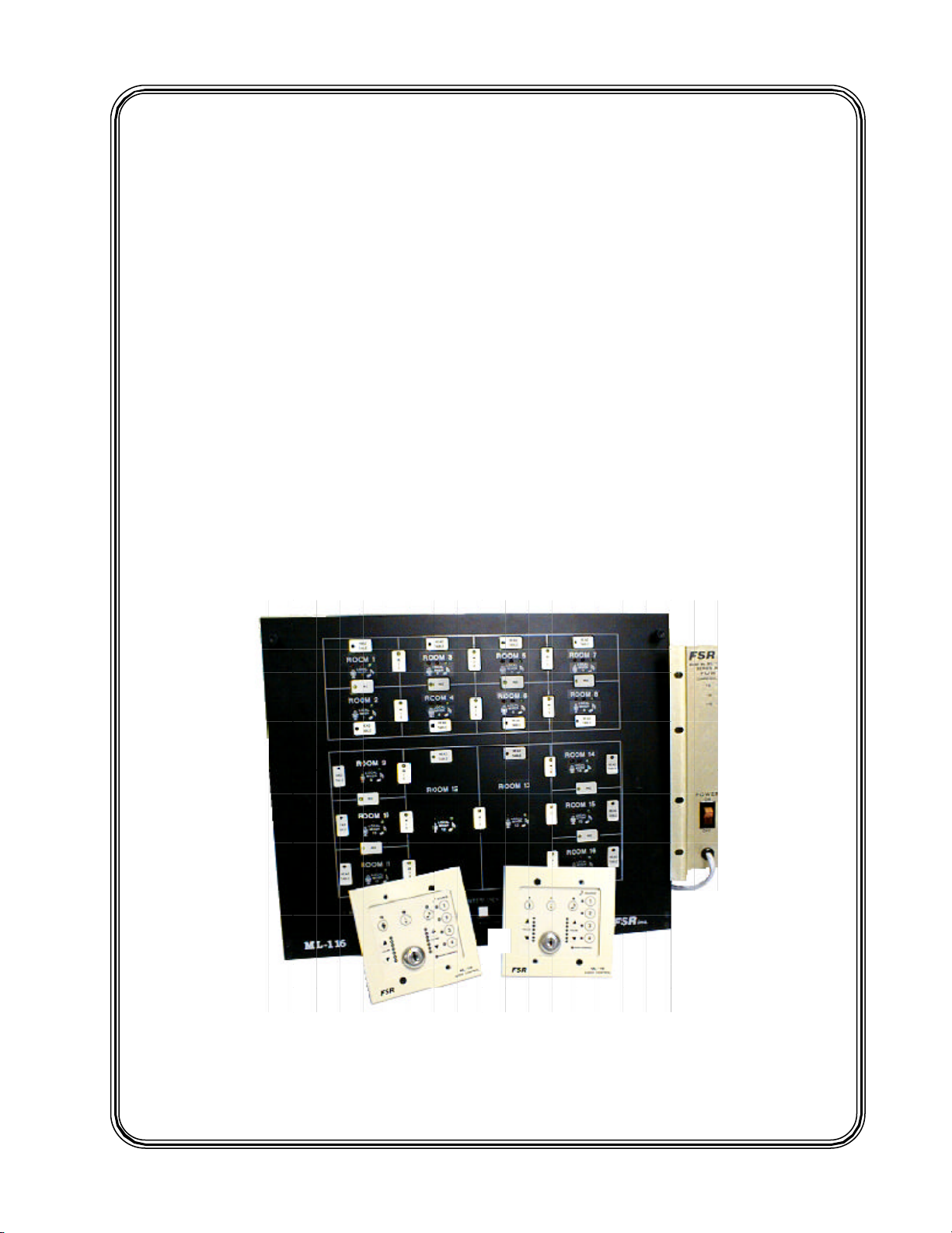
FSR
ML-116
ROOM COMBINING SYSTEM
INSTALLATION
MANUAL
244 Bergen Boulevard, West Paterson, NJ 07424 Tel 973-785-4347 Fax 973-785-3318
E-Mail sales@fsrinc.com Web www.fsrinc.com
47825 LIT1016B
Page 2

Page 3

ML-116 INSTALLERS MANUAL
CONTENTS
Introduction......................................................................................... 5
Unpacking............................................................................................ 6
Photograph of System Components.................................................. 7
Equipment Placement......................................................................... 8
Grounding............................................................................................ 8
System Block Diagram........................................................................ 9
Overall View of the System Components.......................................... 11
• Wallplate
• ACU
• Monitor/VU Panel / Monitor/VU Hookup
System Specifications.......................................................................... 16
Audio Connector Wiring.................................................................... 19
Cabling................................................................................................. 20
• Audio
• Control
• Wallplates
System Configuration......................................................................... 22
Dip Switch / Jumper Settings............................................................. 23
• ACU
CPU Card
RA2 Cards
•Wallplates
• Map Panel
Adjustments......................................................................................... 30
Paging System Operation................................................................... 32
Head Table Operation......................................................................... 33
Facility Manager Panel Operation.................................................... 34
Multiple ACU's.................................................................................... 37
Remote Map and Monitor Panels...................................................... 40
Audio / Lighting Systems Intergration.............................................. 41
Map Panel Status Interface................................................................ 42
Page 4

Page 5

FSR
ML-116 INSTALLATION DATA
INTRODUCTION
The design of the ML-116 system takes advantage of current technology to provide a blend of reliability, ease of use, flexibility, and reasonable cost. Designed for Hotels and Conference Centers with
divisible, multi-use meeting rooms, the ML-116 unifies the audio system of each room being joined
together with the touch of a button. Each control panel, speaker, amp, etc. will automatically operate as
one sound system. Any number of rooms (up to 16 per system) can be combined in any number of
groups. Provided custom software allows the system to be tailored to specific system requirements.
The ML-116 eliminates the need for skilled operators and can be used by staff members with minimum
instruction. The combining can be controlled from multiple locations depending on the system options, and specific functions can be controlled from each room. The quality of the sound system is not
compromised by this system. Built-in safeguards prevent system failure due to misuse or failure of one
component.
The entire ML-116 system includes:
o ACU Audio Control Unit (base ML-116 chassis)
o PSA Power Supply
o Wallplates One per room
o MLH-8/16/24/32 Head Table Speaker Controls (optional)
o MAP Graphic Map Panel (optional)
o MON Monitor/VU Panel (optional)
o FMP Facility Manager Panel Interface (optional)
o AUD Remote Audio Monitoring (optional)
o RMAP Remote Map Panel (optional)
o RMON Remote Monitor Panel (optional)
o TC Remote Map and Monitor LCD Touch Panel (optonal)
o CNTL Control System Interface (optonal)
o INT Map Panel Status Interface (optonal)
o LU Lutron® Lighting Interface (optonal)
o IM / UM Installation Manual / User Manual
In each room a wallplate controls music and local input functions (local input on/off, room mixer
enable, music select, and volume up/down switches for local input and music.) A bar graph display is
provided for local input and music.
The security key switch prevents unauthorized control of the system. Dip switches inside the Audio
Control Unit determine whether the key switch interlocks all the wallplate functions, microphone functions only, or no wallplate functions.
The system is shipped in a default setting which will permit instant operation of the system in its usual
configuration. Please refer to the Dip switch/Jumper settings for pertinent details on the switch functions.
Telephone 973-785-4347
page 5
Page 6

FSR
ML-116 INSTALLATION DATA
UNPACKING
Your ML-116 system should contain the following components;
• ACU (audio control unit) This is the large unit and may have the map panel, if
ordered, on the front.
• ML-PSA ( large power supply)
• Wall Plates Room control panels, one for each room in the system. Depending on the
order either 2 or 3 gang wallplates will be shipped. On some installations two
wallplates may be required per room.
• If head tables were ordered you should have an HTBC card, 1-4 HT-8 cards, power supply,
and one or two 19 inch TRAC-BRACs depending on the number of HT-8
cards. Each HT-8 card will handle up to 8 Head Table locations.
• If the Monitor/VU panel was ordered you should have the Monitor Panel and ribbon
connecting cable along with the Monitor Relay Card mounted on a 19 inch
TRAC-BRAC.
• If the Facility Manager Panel was ordered you should have an FM-INT Interface Unit, the
RS-232 interconnect cable, a 3.5" diskette, and a power supply. (*)
• If the Remote Audio feed was ordered you should have an enclosed audio speaker along
with special relay cards (116-MNRL and 116-MNP) mounted on a 19 inch
TRAC-BRAC. (*)
• If the Remote Map Panel was ordered you should have the R-MAP Panel with its power
supply.
• If the Remote Monitor Panel was ordered you should have the R-MON Panel which will
mount on top of the R-MAP Panel.
• If the Lutron lighting interface was ordered then you should have the ML-116-INT & power
supply unit.
• An installation Manual.
• A users Manual.
(*) With multiple ML-116 systems with the FMP or AUX option(s) some duplicate compo
nents are not provided
page 6 Telephone 973-785-4347
Page 7
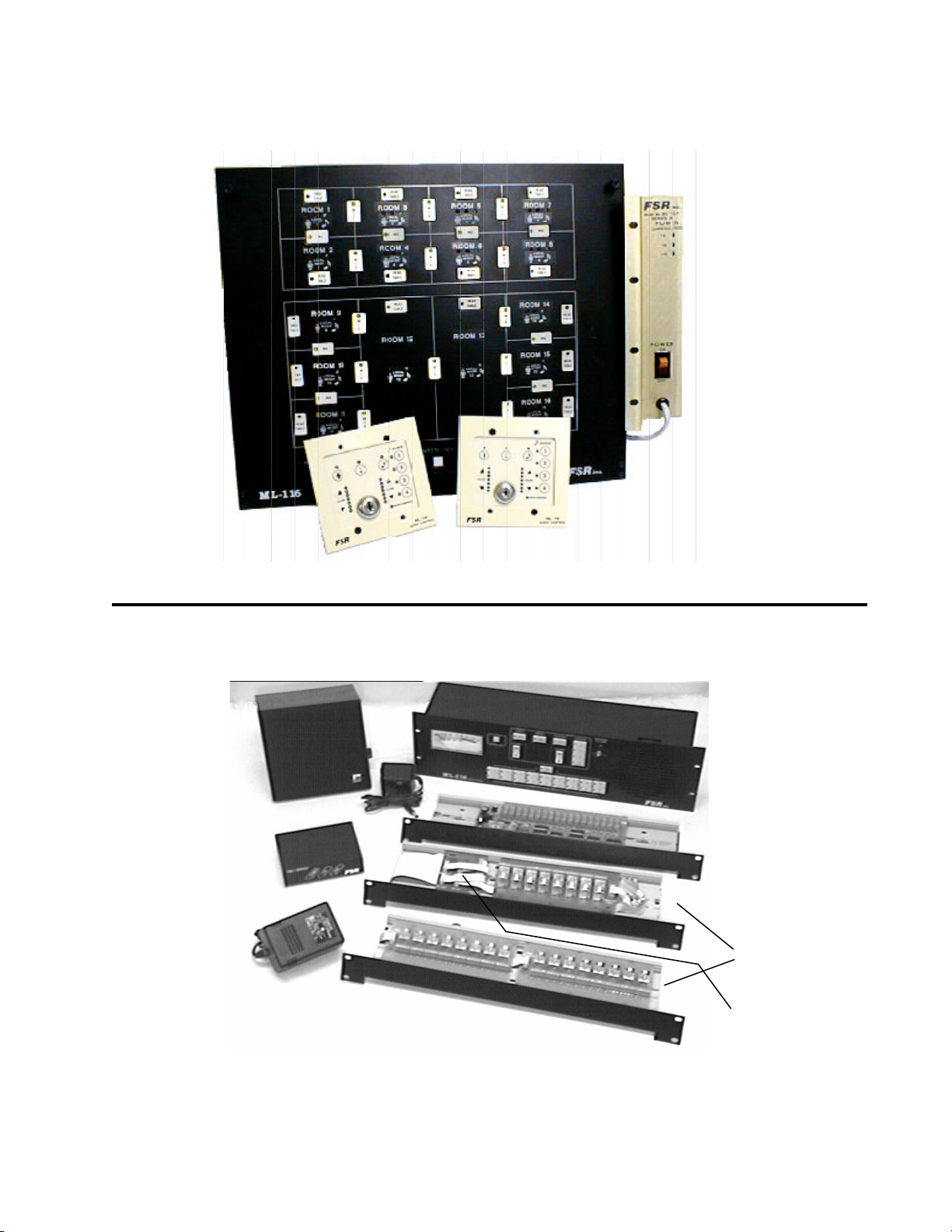
FSR
ML-116 COMPONENTS
AUDIO CONTROL UNIT (GENERIC LAYOUT SHOWING 16 ROOMS)
ACU
ML-116 INSTALLATION DATA
POWER SUPPLY
ML-PSA
AUDIO SPEAKER
FM-INT UNIT
WALL MOUNT
TRANSFORMER
2 GANG WALLPLATES
OPTIONAL SUBSYSTEMS OF THE ML-116 SYSTEM
MONITOR VU PANEL
MONITOR RELAY CARD
HEAD TABLE
RELAY CARDS
HEAD TABLE
BREAKOUT CARD
2
Telephone 973-785-4347
page 7
Page 8

FSR
ML-116 INSTALLATION DATA
EQUIPMENT PLACEMENT
The ACU is mounted first. It should go in the audio rack at eye level usually 55 inches from the
finished floor. The MONITOR VU panel is mounted next and it usually goes immediately above the
ACU.
The ML-PSA is mounted in the same rack as the ACU. It mounts in the rear of the rack usually at
waist level.
The Monitor Relay card, already mounted on the TRAC-BRAC is mounted directly behind the
power amps on the rear rack rails.
If head tables were ordered then the HTBC and HT-8 cards, mounted on a TRAC-BRAC are located
at the rear of the rack behind the power amplifiers.
When the Facility Managers software, with audio monitoring (ML-116-AUD), is ordered then
another TRAC-BRAC with a ML-116-MNRL & MNP is also installed at the rear of the rack close to
the Monitor Relay Card. This completes the rack mounting of the ML-116 components.
The wallplates are mounted next. At least one wallplate is mounted in each room. In larger rooms
two wallplates may be required. They mount in a standard 2 gang electrical box (min. depth 3
inches) and are connected to the cable already pulled. Refer to the section on wallplates to determine
proper hook-up.
If the Facility Managers software with audio monitoring (ML-116-AUD) was ordered then the
enclosed audio speaker, as well as the FM-INT small desk top mounted box, are located in the
Managers Office.
If the Remote Map and/or Monitor Panel was ordered then this unit will be mounted, most likely, in
a service corridor and will wired back to the rack mounted ACU.
If the lighting interface was ordered then the ML-116-INT) unit would be mounted in the lighting
dimmer rack location
GROUNDING
It is strongly recommended that in any rack setup to ensure appropriate power application as
well as superior power surge protection that the FSR Power Conditioning and Sequencing (SPC)
System be utilized.
The ML-116 System, along with the associated mixers, equalizers, and power amplifiers, is a high gain
audio system of some complexity and requires a proper grounding procedure be followed.
The ML-116 equipment has separate audio, digital, and chassis grounds. In some cases you may need
to connect the two grounds. The digital and audio grounds come together on the regulator card located
inside the audio control unit on the left side of the chassis. There is a ground terminal and when it is
connected to a banana jack on this same card the digital and audio grounds will be tied to the chassis
ground.
page 8 Telephone 973-785-4347
Page 9

FSR
ML-116 INSTALLATION DATA
WALLPLATE GROUNDING CONSIDERATIONS
In order to prevent damage to the ML-116 system from ESD (Electro-Static Discharge), it is incumbent upon the installer to carefully consider the grounding of the system. Since the ML-116 is a
digital/audio hybrid, proper ground is essential to maintaining audio quality while preventing damage the electronic circuitry.
The metal faceplate of the ML-116 wallplates must be grounded to prevent damage due to ESD
events. The best way to guard against ESD damage in any system is to return the charge to ground by
the shortest path possible. A direct connection between the faceplate and conduit ground is the most
desirable method. At the same time, the DC ground of the system must be kept isolated from conduit ground, or ground loop noise will result.
The ML-116 wallplates are provided with either a ground wire or a ground jumper to allow for
grounding of the metal faceplate. If the electrical mounting boxes are already grounded, the ground
wire must be insulated or the jumper disconnected to prevent a ground loop. If the electrical box is
not grounded, connect the ground wire to the SHIELD terminal of wallplates so equipped. On
wallplates that have a ground jumper, ensure that the jumper is installed. In systems that do not have
grounded electrical boxes, the ESD ground path is through the shield conductor of the recommended
cable, through the ML-116’s CPU card, and to the chassis of ML-116 rack unit.
ML-116 SYSTEM BLOCK DIAGRAM
Telephone 973-785-4347
page 9
Page 10

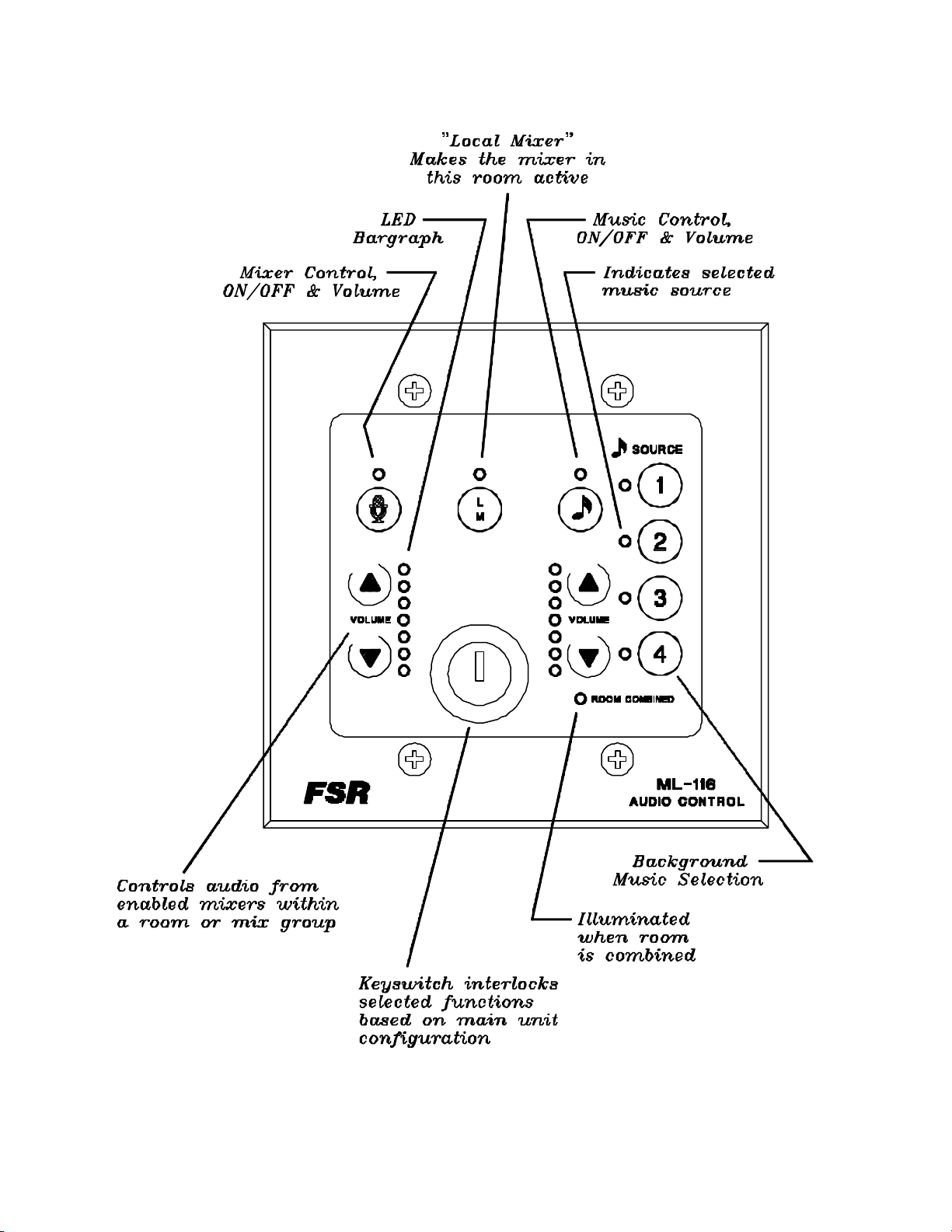
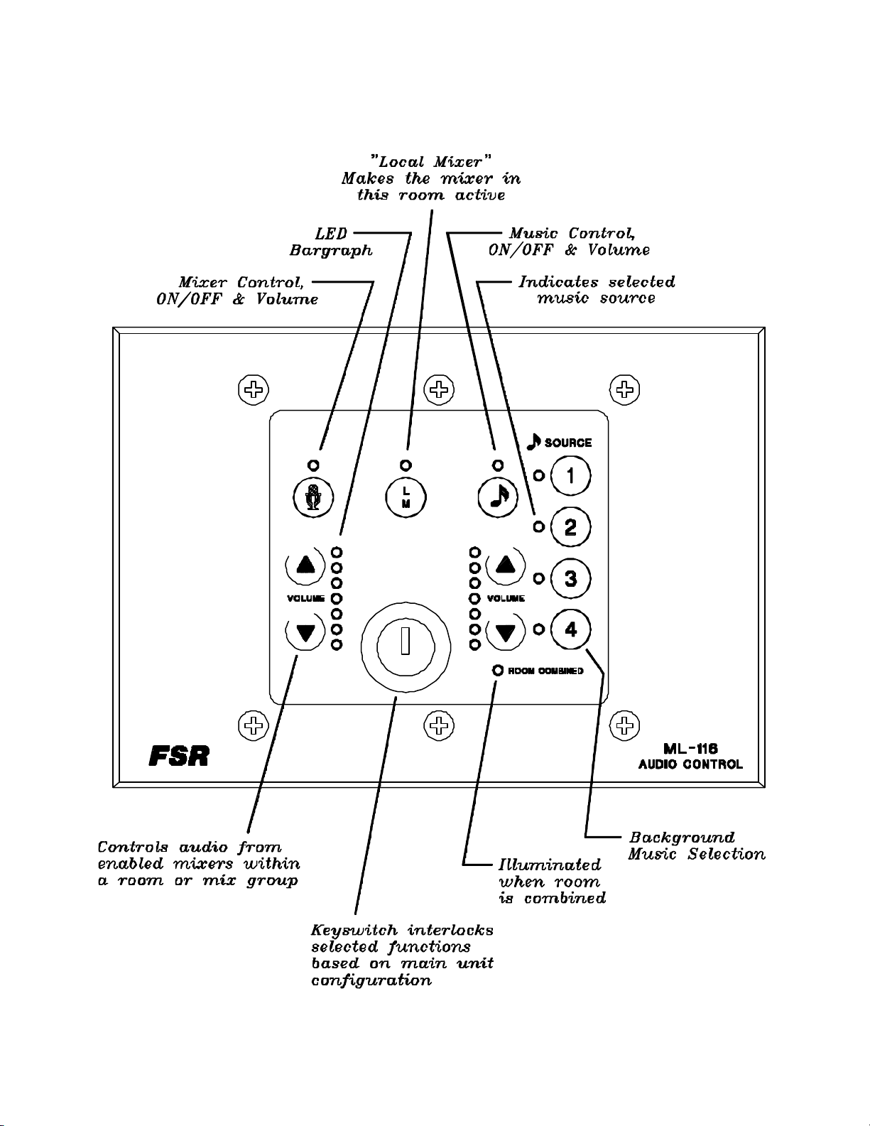
FSR
ML-116 INSTALLATION DATA
A.........There will be two types of wallplates available for use in the ML-116 system; membrane
and LCD. Both control all wallplate functions. These functions include Music Selection,
Room Mixer Enable, Music Enable and Volume, and Local Input On/Off and Volume.
B.........Each room in the system can have two wallplates if desired.
C.........The ACU (audio control unit) is the main unit of the system. It routes the selected music,
adjusts levels, combines rooms, handles communications (between wallplates, map, and
monitor panels), and can talk to other ML-116s. It also controls the paging function.
D.........The HT-8 is a PC board assembly with 8 relays to control the speaker feeds to the head
table locations. These cards are driven by the HTBC board.
E........ The PSA is the Power Supply for the ML-116 system.
F........ The Monitor/VU Panel permits an operator to monitor the audio from any selected room.
It also permits the operation of any wallplate function from this same panel.
G........ The Monitor Relay Card is a PC board assembly of relays that mounts close to the power
amps and provides the audio feed for the monitor panel.
H.........This wall plug-in transformer powers the HTBC and HT-8 cards.
J........ The HTBC Board is essentially a breakout that accepts power and signal input and drives
the HT-8 cards.
These three remaining items are described and shown further on in this document.
K....... This is the R-MAP unit that repeats the data on the rack map panel (see page 40)
L....... This is the R-MON unit that repeats the data on the rack monitor panel (see page 40)
M...... This is the ML-116-INT unit to handle the lighting interface (see page 42)
page 10 Telephone 973-785-4347
Page 11
FSR
ML-116 INSTALLATION DATA
OVERALL VIEW OF SYSTEM COMPONENTS
Telephone 973-785-4347
ML-116 WALLPLATE 2 Gang
MEMBRANE TYPE
page 11
Page 12
FSR
ML-116 INSTALLATION DATA
ML-116 WALLPLATE 3 Gang
MEMBRANE TYPE
page 12 Telephone 973-785-4347
Page 13

FSR
ML-116 INSTALLATION DATA
ACU Description
The Audio Control Unit is the main unit of the system. It routes
the selected music, adjusts levels, combines rooms, handles
communication (between wallplates, map, and monitor panels), and can route audio to other ML-116s. It also controls
the paging function.
Refer to Figure 1 for the following discussion.
The ACU RA2 module provides the audio interface for two
rooms. All RA2 modules are fully interchangeable. The module identifies the two rooms by an ODD and EVEN nomenclature. The numbers that appear on the top of the ACU module slot refer to the room's number in the system. These numbers also correspond to the numbers in each room drawn on
the map panel.
A...This 3 pin connector receives the audio signal
from the ODD room's mixer.
B...This 3 pin connector receives the audio signal
from the EVEN room's mixer.
C...This 3 pin connector provides the audio output to the ODD room's amplfier or EQ.
D...This 3 pin connector provides the audio output to the EVEN room's amplfier or EQ.
E...These four 3 pin connectors receive the background music signals from the facility supplied
sources. The source number over each connector
corresponds to the identification called out on the
room wallplates.
F...This trim control provides limited volume adjustment for each background music source.
G...This 3 pin connector accepts the page audio
signal from the facilities page audio feed. A level
adjust is provided for this input.
H...This 3 pin connector may be used to provide
limited combining capability among multiple ML116 systems.
Telephone 973-785-4347
page 13
Page 14
FSR
ML-116 INSTALLATION DATA
J...The ML-116 regulator module accepts unregulated DC voltages from the ML-116 PSA, power
supply. A plugable connection is provided to connect to the power supply. LED indicators are provided to monitor the power within the unit.
K - L...The HTP module provides control interface to support paging capabilities. It also provides
the control interface for the head table speaker
switching. Refer to sections titled Paging and Head
Table operation for additional details
M...Com 1 and Com2 update serial ports (DB-9 x
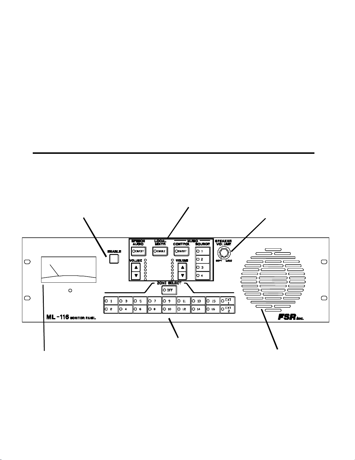
MONITOR/VU PANEL
ENABLE SWITCH
MUST BE DEPRESSED
TO OPERATE ANY
SWITCH ON THE
ROOM PANEL
DUPLICATES THE ROOM
WALLPLATE
2 male)
N...Wallplate/monitor interface connectors. These
four points are where all room wallplates are connected. The monitor panel, the remote map/monitor and the ML-116-INT interface unit are connected to one of these points. Four points are provided to ease system installation.
P...Facility managers panel interface connector.
Refer to section on this topic for additional details.
MONITOR
SPEAKER VOLUME
CONTROL
VU METER
SELECTS THE ROOM OR EXTERNAL ZONE TO BE MONITORED
SPEAKER
Monitor/VU Panel Installation
While the Monitor/VU panel is optional, it is recommended for all systems comprising more than six
rooms. The installation of this feature requires the Monitor Relay Card in addition to the above
panel. This relay card is supplied mounted in an FSR TRAC-BRAC simplifying the rear rack mounting of this card.
page 14 Telephone 973-785-4347
Page 15

FSR
ML-116 INSTALLATION DATA
The interconnect cable from the ML-116 ACU to the Monitor panel is the same wire used to connect
the wallplates. The cable from the Monitor panel to the Monitor relay card is supplied with the
system.
Monitor/VU hookup diagram
rear of the Monitor/VU Panel
connect to any
one of these 4
terminal blocks
an 8' ribbon cable (14 conductors) is supplied (MNRL-CBL)
from room 16's amplifier output
EXT 1 (aux amp A)
EXT 2 (aux amp B)
Not used in this application
partial view of the
CPU module
(located in the ACU)
Monitor relay card
rooms one thru sixteen
from room 1's amplifier output
this card requires that all amplifiers
have a 70 volt speaker drive
Telephone 973-785-4347
page 15
Page 16

FSR
SYSTEM SPECIFICATIONS
Audio Control Unit (ACU)
Audio Connections: RA2 Module (one per two rooms)
Inputs: electronically balanced 20K Impedance (unbalanced 10K), 3 pin screw termi
nals
Outputs: 600 ohm transformer coupled (balanced) 3 pin screw terminals
Audio Connections: MP Module (music/page module)
Inputs: 600 ohm transformer coupled (balanced) 3 pin screw terminals
System Level adjust range: +7 dB to -20 dB
Input TrimLevel Adjust Range: (Page and Music input level adjust trim pots) +2.5 to -7.5 dB.
Tie line output: 600 ohm transformer coupled (balanced) 3 pin screw terminals
Audio Gain:
Music (with respect to input level)
Volume Reset: 0 dB +/- 1dB
Full Down: -18 dB +/- 1 dB
Full Up: +4 dB +/- 0.5 dB
Local Input (with respect to input level)
Volume Reset: 0 dB +/- 1dB
Full Down: -18 db +/- 1 db
Full Up: +4 db +/- 0.5 db
Page Input: 0 db +/- 1 db
Maximum Output Level: +20 dBm
ML-116 INSTALLATION DATA
Noise Floor: -75 dBm typical. Conditions: Full mix, Mixer Enables on, Local Inputs off,
input open, outputs 600 ohm terminated
-70 dBm typical. Conditions: Full mix , Mixer Enables on, Local Inputs on,
Volume set to 0 dB. inputs open, outputs 600 ohm terminated
Crosstalk: -85 dB typical. Conditions: No mix, Mixer Enables on, Local Inputs on,
Volume set to 0 dB. +10 dBm 1KHz. signal into any input, measure any output
-80 dB typical. Conditions: Full mix, Mixer Enables on, Local Inputs on,
Volume set to 0 dB. +10 dBm 1KHz. signal into any music or page input.
Size: 19 inches wide, 14 inches high (8RU), 13 inches deep
Mounting: Standard rack mounting, usually located 55 inches above finished floor.
page 16 Telephone 973-785-4347
Page 17

FSR
Wall Plates
Size: 6 1/4 inches wide by 4 1/2 inches high, approximately 2.5 inches deep
Mounting: fits standard 2 or 3 gang electrical wall box with four or 6 screws
Switches: membrane
Connector: 5 pin connector
Cable: West Penn #3651 or 3751 (see page 13 for details)
Power Supply (PSA)
Size: 3 1/2 inch high, 6 inches deep, 10 inches long (approximately)
Mounting: rear rack rail
Input power: 105 to 132 VAC, 50/60 Hz, 100 watts
Output: +15 volts, +25 volts, -25 volts nominal
Fuse: 2 amp
Switch: power on/off (lighted rocker switch)
Interconnect: 8 foot cable supplied, 5 conductor stranded
Indicators: three LED indicators, one for each of the unregulated voltages
ML-116 INSTALLATION DATA
MON Monitor/VU Panel Assembly (optional)
Monitor/VU Panel
Input: 70Volt speaker level
Size: 19 inches wide, 5 1/4 inches high(3RU), 4 1/2 inches deep overall
Mounting: standard rack rails
Monitor Relay Card (supplied with the Monitor/VU card)
Size: 3 1/4 inches wide, 9 1/2 inches long, 1 inch high, comes already mounted in a
19 inch FSR TRAC-BRAC
Mounting: rear rack rails
MLH Head Table Speaker Assembly (optional)
Head Table Breakout Card (HTBC)
Size: 3 1/4 inches wide, 2 3/4 inches long, 1/2 inch high
Power: HT-PS supply provided
Head Table Relay Card (HT-8)
Size: 3 1/4 inches wide, 7 1/4 inches long, 1 inch high, can have up to four of these
cards per system
Mounting: rear rack rails, both the HTBC and the HT card come already mounted in a 19
inch FSR TRAC-BRAC
FM Facility Manager Control (optional)
Facility Managers Panel (FM-INT)
Size: an enclosed box 3 1/2 inches wide, 5 inches long, 1 1/2 inches high
Mounting: sits on the managers desk
Power: a wall mounted power supply
Telephone 973-785-4347
page 17
Page 18

FSR
ML-116 INSTALLATION DATA
AUD Audio Monitor Add-on (optional)
Size: processor card(MNP); 3 1/4 inches wide, 7inches long, 1 1/2 inches high
speaker switching card (MNRL); 3 1/4 inches wide, 9 1/2 inches long, 1 1/2
inches high
Mounting: both the MNP and the MNRL cards come already mounted in a 19 inch FSR
TRAC-BRAC
Speaker: enclosed in an attractive baffle 7 inches high, 6 1/2 inches wide, 5 inches deep
R-MAP Remote Map Panel (optional)
Size: 20" wide, 14" high, 2 1/8" deep
Mounting: standard rack rails
Power: 120 VAC, via knockouts in case
R-MON Remote Monitor Panel (optional)
Size: 20" wide, 5 1/4" high, 2 1/8" deep
Mounting: standard rack rails
Power: 120 VAC, via knockouts in case
CTRL Control System Interface (optional)
Size: 8 1/2", 1 1/2" high, 4 3/4" deep
Mounting: use supplied rack mounting bracket
Power: wall wart 9 VAC
INT Map Panel Status Interface (optional) & LU Lighting Interface (optional)
Size: 7 1/2" wide, 7 1/2" high, 2 1/2" deep
Mounting: panel mount
Power: wall wart 9 VAC
page 18 Telephone 973-785-4347
Page 19

FSR
ML-116 INSTALLATION DATA
AUDIO CONNECTOR WIRING
In any professional sound system with many inputs and outputs it is strongly recommended that all
audio wiring be balanced. All the audio inputs and outputs on the ML-116 system are balanced.
In a balanced configuration the connectors are wired as follows:
HIGH
LOW
SHIELD
SOURCE
HIGH
LOW
SHIELD
OUTPUT
DEVICE
If due to some equipment limitations unbalanced wiring must be used then the proper way to wire
the audio connectors follows:
Input Wiring (single wire with overal shield)
HIGH
LOW
SHIELD
Input Wiring ( two conductor overal shield)
HIGH
LOW
SHIELD
Output Wiring (single wire with overal shield)
SOURCE
SOURCE
HIGH
LOW
HIGH
LO
SHIELD
Telephone 973-785-4347
OUTPUT
DEVICE
Output Wiring (two conductor with overal shield)
OUTPUT
DEVICE
page 19
Page 20

FSR
ML-116 INSTALLATION DATA
CABLING
AUDIO
All audio connections to the ACU are 3 pin connectors with pin 1 ground, pin 2 High, and pin 3
Low.
Head table speaker operation is optional and is contained on a PC board. This board mounts on a
TRAC-BRAC, usually adjacent to the audio power amplifiers. There are two terminals for each
speaker output and two terminals for the amplifier input. However, only one side of the line is
switched. The other set of terminals are for convenience. The plug-in wall transformer powers the
HTBC (head table break out card), which in turn powers the HT-8 relay cards. Up to four HT-8
cards can be implemented per system.
The monitor relay card is associated with the Monitor VU panel and provides the actual speaker
switching . Both sides of the speaker line is switched. A plug-in wall transformer powers the card.
CONTROL WIRING
The following diagram illustrates the control wiring for the ML-116 system. Refer to following
sections for details on head table, page, and facility manager operational hookup diagrams.
page 20 Telephone 973-785-4347
Page 21

FSR
ML-116 INSTALLATION DATA
WALLPLATES
The wallplates can be wired in either a home run (star) or modified daisy chain configuration.
Use two twisted pair 22 AWG stranded, with an overall shield (West Penn # 3651) if the home run
configuration is employed for each wallplate and total distance to any wallplate does not exceed 1000
feet.
Use two twisted pair 18 AWG stranded, with an overall shield (West Penn #3751) if the wallplates are
daisy chained together (it is recommended to only daisy chain 6 wallplates per home run) with no more
than 1000' total wire length.
Refer to the figure for terminal identification. Four screw terminals are provided on the rear of the
wallplate for cable hook-up.
Note: it is essential that in any
REAR OF WALLPLATE
case the voltage on pin 1 on the
wallplate connector be in excess
of 8 volts DC..
TERMINAL POSTION
1 POWER +
2 POWER GROUND
THIS IS ONE PAIR
3 DATA HIGH
4 DATA LOW
THIS IS ONE PAIR
5 SHIELD IF USED
One is installed in each room and is wired to the ACU. The wallplates mount in a standard 2 or 3 gang
electrical box. An eight position dip switch on the rear of the wallplate is used to assign the wallplate's
room address. This switch is preset at the factory to the area identified on the front of the wallplate
itself, but should be checked prior to installation.
The system is shipped in a default setting for all dip switches which will permit instant operation of the
system in its usual configuration. Please refer to the DIP SWITCH section for details on all the dip
switch functions.
Telephone 973-785-4347
page 21
Page 22

FSR
ML-116 INSTALLATION DATA
SYSTEM CONFIGURATION
The ML-116 system allows the user greater flexibility than any other room combining system made
today! No other system allows the user the choice of 4 music input selections, or provides the local
mixer enable that greatly reduces distortion when combining rooms. The rack mounted Audio Control
Unit (ACU) unit can handle up to 16 rooms and was designed to be linked together with other ACU’s
to control the audio in up to 128 rooms.
The basic system configuration consists of an ACU, Map Panel, Monitor Panel, Wallplates and an
optional Facility Manager’s Panel. Each unit of the ML-116 has its own unique responsibility and
processing is distributed throughout the entire system. The responsibilities of each unit is described
below:
ACU UNIT
The ACU is the rack mounted brain of the system. It contains the CPU module, one RA2 (room audio)
module per 2 rooms, a Regulator module, a MP (music page input) module, and an HTP (head table
and page control) module.
The CPU module is the central controller of the system. It is responsible for controlling the other
modules and receives data on what to do from the Wallplates, Monitor Panel, and Map Panel and/or
FM Panel. It uses dip switches (discussed in the Dip switch/Jumper section) to determine settings and
operating modes.
WALLPLATES
The wallplates are microprocessor controlled modules that are used for room audio control. They are
responsible for setting Local Input on/off, Music on/off, Music Selection, Local Input Volume, Music
Volume, and Local Mixer Enable on/off. The Section on Dip Switches describes the settings used on
the wallplates and those on the CPU module that set modes on the wallplates.
MAP PANEL & REMOTE MAP PANEL
The Map Panel is responsible for controlling the system setup by mixing rooms together and selecting
head table locations. It is microcontroller based and communicates to the CPU module. The map panel
is fabricated at the factory and is not configurable on site.
MONITOR PANEL & REMOTE MONITOR PANEL
The monitor panel is also a microprocessor controlled module placed near the ACU unit which allows
the user to ‘monitor’ the settings in a room. The user can adjust those settings by using the monitor
panel’s built in ‘wallplate’.
FACILITY MANAGER’S SOFTWARE PANEL, including the FM-INT Unit
This is a software program that runs on a PC and controls the system by imitating the Map Panel and
has the ability to combine rooms without mix switches. It is customized and is not configurable. It
communicates over two twisted pairs to the ACU using a multidrop proprietary protocol. The FM-INT
Unit interfaces this line to the computer. An enclosed audio speaker would also be used if the audio
feed was implemented.
page 22 Telephone 973-785-4347
Page 23

FSR
ML-116 INSTALLATION DATA
DIP SWITCH / JUMPER SETTINGS
ACU Audio Control Unit, CPU Module
The CPU Module contains sixteen (16) dip switches which will allow users to customize the system to
a large degree. These switches in addition to two jumpers on each room audio (RA) module, allow the
user to select such options as simultaneous microphone and music operation, key switch interlock
functions, ramp speed, etc. The definition of the switches are as follows:
Dip switch Factory Setting Explanation
1 open Memory Volume
2 open Preset Volume
3 open Reserved
4 open Enable Mode
5 open [Wall Plate
6 open Interlock Mode]
7 open Reserved
8 closed Cold Start Select
9 open Select multiple Systems
10 open Select multiple Systems
11 open Select multiple Systems
12 open Select multiple Systems
13 open Reserved
14 open If Monitor Panel Present
15 open If FMP present
16 open If Map Panel Present
Dip switch 1 - Initial Volume Memory Option - closed the volume is determined by the dipswitch
2 setting, if open the volume is restored to level that was last set.
Dip switch 2 - Preset Volume - Setting determines the power up default volume level, if closed
the volume initializes to -12 db, if open it initializes to 0 db.
Dip switch 3 - Reserved
Dip switch 4 - This dip switch allows simultaneous operation of voice and music. If the dip
switch is open then the system is in normal mode, the voice and music are exclusive. This is commonly referred to as the pre-enable mode. If the dip switch is closed, both voice and music can be
operated at the same time (simultaneous mode). The system is shipped with this dip switch in the
open position.
Telephone 973-785-4347
page 23
Page 24

FSR
ML-116 INSTALLATION DATA
Dip switch 5 and 6 - Wallplate Interlock Mode.
If Switch 5 is closed, the wallplate keyswitch has no effect on the operation of the wallplate. The local
input and music sections of the wallplate are always active. In this position Switch 6 is not used.
If Switch 5 is open and Switch 6 is open, the ‘partial interlock’ mode is selected. This is the default
mode for the ML-116. In this mode, the keyswitch interlocks only the microphone section of the
wallplate.
If Switch 5 is open and Switch 6 is closed, the ‘full interlock’ mode is selected. In this mode, the
wallplate cannot be operated without the keyswitch.
Dip switch 7 - Reserved
Dip switch 8 - System Clear When system power is removed the ML-116 has the capability to
save the state of the system including the combining status of all the rooms and the state of each room’s
local input and music selectors and volume. If open, the ML-116 saves its states, if closed it initializes
to a “clear” state.
Dip switches 9 to 12 are used to address multiple ACU's. The coding is as follows:
12 11 10 9 12 11 10 9
O O O O - ACU 1
O O O C - ACU 2
O O C O - ACU 3
O O C C - ACU 4
O C O O - ACU 5
O C O C - ACU 6
O C C O - ACU 7
O C C C - ACU 8
Note: C=dip switch is closed, O= dip switch is open
These switches would only be used with a Facility Managers Panel and multiple ML-116 systems.
C O O O - ACU 9
C O O C - ACU 10
C O C O - ACU 11
C O C C - ACU 12
C C O O - ACU 13
C C O C - ACU 14
C C C O - ACU 15
C C C C - ACU 16
Dip Switch 13 - Reserved
Dip Switch 14 - Monitor Panel Present (switch open)
page 24 Telephone 973-785-4347
Page 25

FSR
ML-116 INSTALLATION DATA
Dip Switch 15 - Facility Manager’s Panel Present (switch open)
Dip Switch 16 - Map Panel Present (switch open)
Room Audio (RA2) Card Jumper Settings
The ML-116 RA2 cards contain two jumper fields to allow page mode configuration The jumpers
determine whether or not "Normal Paging" occurs during Mic or Music functions. A four position
jumper field is provided for each room. Each bank of jumpers is clearly labeled as either “Low Room”
or “High Room”. Within a bank of jumpers, one pair is labeled “Page Thru Music” and the other pair
“Page Thru Mic”. Within a pair of jumpers, one jumper is labeled “Y” for yes, and the other “N” for no.
The system is factory configured to allow Normal Mode Paging during music but not while mics are
enabled (Page Thru Mic = Y; Page Thru Music = N). You may reconfigure the system to operate as
required on a room by room basis. For example, to allow Normal Mode Paging to occur during Mic and
Music, set both the Page Thru Mic and the Page Thru Music jumpers to Y. In most cases, all rooms
within a system should be configured with the same jumper settings to ensure consistent page operation.
In certain cases, it may be desirable to set the page jumpers differently for different rooms. An example
of this would be when a single ML-116 system is used to control two different ballrooms or a single
ballroom with a surrounding corridor.
WALLPLATES
The wallplates used in the ML-116 system are membrane. They control all wallplate functions. These
functions include Music Selection, Local Mixer, Music Enable and Volume, and Microphone Enable
and Volume.
When the wallplates sense a key press it waits for a poll from the ACU then it sends a message to the
ACU which will return an update message. The wallplates will then check for another keypress and
repeat. Internal flags will prevent the wallplates from acting on the same keypress until the update
message is returned. This whole process occurs within a fraction of a second.
The wallplates communicate with the ACU over a RS-422 line and are addressable. This address is a
5 bit address (0-31) allowing the use of up to two (2) wallplates per room.
Telephone 973-785-4347
page 25
Page 26

FSR
ML-116 INSTALLATION DATA
Membrane Wallplate Dip Switch Settings
The ML-116 allows for up to 32 wallplates: 2 per room up to 16 rooms. The wallplates must be
individually addressed. The addresses are set by setting the dip switches on the back of the wallplate.
The address is a binary code representing the room number minus one, given on switches 1 through
4 with a closure representing a 1.
SWITCH 1 2 3 4 SWITCH 1 2 3 4
ROOM 1 0 0 0 0 ROOM 9 0 0 0 1
.
Note: 0= switch open
1= switch closed
ROOM 2 1 0 0 0 ROOM 10 1 0 0 1
ROOM 3 0 1 0 0 ROOM 11 0 1 0 1
ROOM 4 1 1 0 0 ROOM 12 1 1 0 1
ROOM 5 0 0 1 0 ROOM 13 0 0 1 1
ROOM 6 1 0 1 0 ROOM 14 1 0 1 1
ROOM 7 0 1 1 0 ROOM 15 0 1 1 1
ROOM 8 1 1 1 0 ROOM 16 1 1 1 1
Switch 5 is used for rooms with two wallplates. In a two wallplate room, one and only one of the
wallplates (it does not matter which one) should have switch five closed.
Switches 6 through 8 are used for factory self tests and should be open for normal use.
SWITCH POSITIONS
1-5 ADDRESS
6-8 FACTORY USE ONLY
Picture of rear of wallplate
page 26 Telephone 973-785-4347
Page 27

FSR
ML-116 INSTALLATION DATA
Wall Plate Functions
All wallplates will handle these functions in the same way.
Speech/Audio
Alternating action switch that enables/disables audio from any selected mixers within a mixed group.
“Pre-selects” audio from any selected mixers in a mixed group when music is playing.
Local Mixer
Alternating action switch that enables/disables audio from the mixer associated with a given area to be
heard in the entire mixed group. The switch remains independent of the corresponding switch on other
panels within a mixed group. This switch tracks with local input in a single room and will automatically
turn on in the first room in a mixed group to enable local input.
Music
Alternating action switch that activates selected music source within each room or a mixed group of
rooms.
Music Select 1-4
Selects the music source within each room or a mixed group of rooms.
Up/Down Volume (Speech)
Ramps volume up/down within each room or a mixed group of rooms. Associated bar graph indicates
level and is active only when local input is audible. All bar graphs within a mixed group will track
together.
Up/Down Volume (Music)
Ramps volume up/down within each room or a mixed group of rooms. Associated bar graph indicates
level and is active only when Music is enabled. All bar graphs within a mixed group track together.
Keyswitch
Interlocks (disables) certain groups of switches on the wall plate as determined by the selected option
jumpers.
Telephone 973-785-4347
page 27
Page 28

FSR
ML-116 INSTALLATION DATA
MAP PANEL
The ACU may have a Map Panel that will control the combining of rooms. Every system has a unique
panel layout reflecting the actual layout of the rooms. The Interlock button on the Map Panel is used to
enqble all switches on the map panel, while preventing accidental mixing or unmixing. The ACU will
take the rooms that are combined and form a group entry for those rooms. This means that all the
wallplates in those grouped rooms will act identically and all the group's mix LED's will be on.
The normal operation of the Map Panel is to combine rooms that are adjacent to one another or have a
common wall. On special order, the Map Panel can be set up to mix one room to a non adjacent group
but needs to be defined prior to design. The user would have to know that they wanted that capability
and make that known to FSR when the Map Panel is submitted for sign off.
LEDs are used to indicate Speech or Music, Head Table Switch enabled, and which rooms are combined. The LEDs used for combining will automatically be lit if the combining of rooms included on
the switch is included in a group.
Sample layout of map panel
page 28 Telephone 973-785-4347
Page 29

FSR
ML-116 INSTALLATION DATA
MAP PANEL (continued)
Explanation of MAP switch controls:
INTERLOCK SWITCH
This switch must be depressed (operated) in order to operate any switch on the MAP panel. It prevents accidental operation.
MIX SWITCH
When any MIX switch is operated the associated LED illuminates indicating that those two areas
(rooms) are joined. In joining many rooms into one setup just keep operating the appropriate MIX
switches until the group is complete. To break apart a group of rooms just operate any of that groups'
MIX switches and the whole group will disband.
HEAD TABLE SWITCH
This switch, when operated, will cutout the speakers over that location whenever the mic's are active
and will reinstate those same speakers whenever the mic is preselected or off. This the same as
saying that the speakers are active when music is playing but shift to inactive when the mic is active.
This switch cannot be deactivated when the microphones are on.
Explanation of MAP LED operation:
MIX SWITCH LED's
These amber LED's illuminate when the two adjacent areas (rooms) are mixed.
HEAD TABLE LED's
These red LED's illuminate to indicate that the head table in that area(s) has been selected.
MICROPHONE LED's
These red LED's illuminate whenever a microphone (mixer) is either selected or is active.
LM (local mixer) LED's
These green LED's illuminate whenever the LM is selected or, in the case when the room is unmixed
it will automatically be illuminated since that mixer will be active.
MUSIC LED's
These green LED's illuminate whenever the music input is active (music is playing in the room).
MAP PANEL LOCKOUT LED
When this red LED illuminates it locks out the map panel. This will only happen if the Facility
Manager option is in place and it commanded a non-adjacent room be added to a group.
Telephone 973-785-4347
page 29
Page 30

FSR
ML-116 INSTALLATION DATA
ADJUSTMENTS
As with any high performance audio system, proper adjustment is key to achieving optimum S/
N (signal to noise) ratio and performance characteristics.
Once the system is fully assembled including the mixers, amplifiers and other audio processing equipment, you may begin.
In order to properly calibrate the system, you will need a signal source capable of providing a mic and
line level signal. You will also need a VTVM or other instrument that can measure voltages, preferably
with a dBm scale.
Begin by injecting a 1 Khz. typical mic level signal into a mic input of the Room One mixer. Monitor
the output of the mixer using the VTVM while adjusting the mixer channel and main out controls to
achieve a 0 dBm level. The mixer controls should not be set to their extreme settings for best performance. Mark the settings so that users may re-establish them after changes are made. Continue by
moving the input signal to each of the mixers mic input channels, and calibrating them in turn.
CAUTION: At no time in the following procedure should you change levels by adjusting the
volume up down switches at the Wallplates or ML-116 Monitor Panel. Doing so will invalidate
your calibrations resulting in a lot of wasted time.
If you should accidently alter the volume settings, reset the system to a known state by turning
the power off and on, and reselecting the desired settings.
Next , using the ML116 Monitor Panel or Room Control Panel, set Room One to Local Mixer on, Mics
On. The Mic volume bar graph should illuminate the third led from the top. If not, consult the dip
switch setting section of this manual to reset the factory settings. Check the output level of Room One’s
audio card to confirm unity gain through the ML-116 system. Proceed to the output of each successive
audio component in Room One’s audio chain, adjusting as necessary to achieve 0 dBm. Stop at the
power amplifier input.
Move the signal source to the first mic input of the next mixer, and repeat the procedure for Room Two.
Continue in this manner until all rooms are complete.
Continue by setting Room One’s wallplate to Music On, Mic and Local Mixer Off. Select music source
one. The Music volume bar graph should illuminate the third led from the top. Inject the anticipated
nominal music level into Music Input Source 1. Adjust the associated gain trim pot ( just below the
input connector) to yield 0 dBm at the output of the ML-116 audio card. Select the next music source
and repeat this procedure until all four busses are calibrated.
If the paging feature of the system is to be used, inject the anticipated level page signal into the page
input connector. Ground the Priority Page and All Call terminals of the page control terminal block.
Adjust the page gain trim pot to obtain 0 dBm at the output of the ML-116 audio card.
page 30 Telephone 973-785-4347
Page 31

FSR
ML-116 INSTALLATION DATA
At this point, the entire system is calibrated, with the exception of the power amplifier gain setting. To
set the power amplifier gain, you will require some equipment to measure SPL in the room area. Begin
by mixing all room areas together, and opening all divisible meeting areas. If your system consists of
several nonmixable subsections, mix all rooms that are possible.
Set all area wallplates to Music On, Mic Off. Inject the anticipated level signal into the Music Source
One input bus. Using the SPL measuring instrument, monitor each room and adjust each power amplifier as necessary to achieve a uniform level throughout all areas.
Keep in mind that the ML-116 system will allow volume adjustment of +4 to -18 dB with respect to
unity, so you will want to adjust the amps close to the maximum desired level during this procedure.
The adjustment procedure is now complete.
Telephone 973-785-4347
page 31
Page 32

FSR
ML-116 INSTALLATION DATA
PAGING SYSTEM OPERATION
The ML-116 system supports the integration of a new or existing paging system. A Page Audio input, Page Control Room
Selects, and Normal/Priority mode page selects are provided for interface to the system. Option jumpers on each audio card
determine under what conditions normal mode page audio will be heard in the rooms.
The actual paging operation of a particular system will depend upon how paging was implemented by the audio system
design engineer/installing contractor.
The system supports two primary paging modes; Normal Paging and Priority Paging. During a Priority mode page, the room
audio will be muted and the page audio will be unconditionally switched into the selected rooms, regardless of room wallplate
settings. The page audio level is controlled only by the pre-configured amplifier gain settings, and page input level adjust
control on the ML-116 ACU. Any selected audio ( Mics and/or Music playing in the selected rooms) will be disabled for the
duration of the page. Caution should be used when selecting Priority mode paging to guard against interrupting any
meetings in progress.
During a Normal mode page, page audio will be switched into the selected rooms based on the current wallplate settings in
conjunction with the page configuration jumper settings. As shipped from the factory, Normal paging will occur during
music operation, but will be automatically disabled if Mic audio is enabled in the selected room. During a Normal page, page
audio will be mixed with any selected audio in the room ( Music only, based on factory settings). The page audio level is
controlled only by the pre-configured amplifier gain settings, and page input level adjust control on the ML-116 ACU. As
with the Priority mode paging, page volume level does not depend upon wallplate volume settings.
Users are encouraged to consult with their installing contractor to configure the ML-116 system paging options so as to
optimize the operation of a particular installation.
To initiate paging, select the desired rooms to be paged. Select the desired page mode, Normal or Priority, and speak into the
microphone. Page audio does not go through until both room and page mode selections are made. To end paging, deselect
page mode first, and then deselect rooms.
Typical Hookup Diagram
to ACU,
page input
partial view of the HTP
module in the ACU
page 32 Telephone 973-785-4347
23
Page 33

USING PRIORITY PAGE AS AN “ALL MUTE” FUNCTION:
Create a short from the “ALL CALL” and “PRIORITY” terminals to the “GND”
on the HTP card through the relay maintained NO contacts on the external
control system. system.
Without page audio input present on the MP card input terminals, the mike and
music audio will be muted for the duration of the relay closure.
Page 34

FSR
ML-116 INSTALLATION DATA
HEAD TABLE OPERATION
The head table switches on the MAP panel control relays that switch speakers located over a head
table location, on or off. When the head table switch is activated those aforementioned speakers are
disconnected whenever the microphone is in use, to eliminate audio feedback, and are connected in
all other modes of operation.
The installation of the head table controls requires the HTBC card along with the associated HT-8
cards be located in the rear of the rack housing the power amplifiers. Each HT-8 module contains
relays for eight head table locations. The ML-116 system has provisions to handle up to 32 head
table positions meaning an installation could have up to 4 HT-8 modules. All these modules come
mounted in an FSR TRAC-BRAC which facilitates rear rack mounting.
All the interconnect cables from the ML-116 ACU to the HTBC and from the HTBC to the HT-8
cards are supplied with the system.
Head Table Hookup Diagram (only one HT-8 is shown, there could be a total of 4)
from wallmount transformer (supplied) ML-HT
BOARD
HTBC
HT-8 BOARD
R M1R M2R M3R M4R M
5
speaker line output to the speakers above the head table location in room 1
R M
6
R M
7
R M
8
partial view of the
HTP module
(rear of ACU)
amplifier output for room 1 in the system
from
Telephone 973-785-4347
page
33
Page 35

FSR
ML-116 INSTALLATION DATA
FACILITY MANAGERS PANEL
The Facility Managers Panel (FMP) is a Windows based program that performs all the same functions
as the Map Panel and adds additional capability. The most important of which is the ability to mix
nonadjacent rooms. The display of the FMP is a bit mapped image of what the Map Panel looks (or
would look) like. It can take the place of the Map Panel and can perform the functions of the wallplates.
When the FMP starts it requests status from the ACU. The ACU responds with group information if
any. The ACU will update the group information if a Map Panel is present and has defined a group.
The FMP uses the group information to update the Windows display to reflect those rooms that have
been selected into groups.
FMP Installation
To install the FMP a cable is run from the ML-116 ACU to the manager's office. This cable is two
twisted pairs with an overall shield and they connect to the CPU module at the ACU. In the managers
office the cable terminates in the FM-INT unit which in turn plugs into com port 1 or 2. If the audio
option was ordered then another cable, specifically a standard audio line (one twisted pair with an
overall shield) would also be run. It connects from the left-most terminals on the Monitor Relay Card
and terminates in the speaker enclosure mounted in the manager's office.
Hookup Diagram Overview (refer next page for detailed hookup)
These two items are
located in the
managers office
to any Windows
compatible computer
audio line
connects here
These are interconnected
partial view of the
Relay card (116MNRL)
partial view of the
CPU module (rear
of ACU)
Partial view
of small
micro board
mounted on
TRACBRAC with
Relay card
self contained speaker
with volume control
(supplied)
page 34 Telephone 973-785-4347
Page 36

FSR
ML-116 INSTALLATION DATA
Facility Managers Panel Hookup Diagram (including the optional audio feed)
To wallmount transformer
(supplied
)
116-MNRL
116-MNR
Located in Managers Office
L
Optional
Audio Feed
Telephone 973-785-4347
page
35
Page 37

FSR
ML-116 INSTALLATION DATA
Group Functions
The FMP group functions include defining groups, adding rooms to groups, and removing groups.
These functions are similar to the Map Panel except that instead of using the Interlock switch and push
button the user uses a mouse.
Groups are defined as rooms that are combined to become a larger room. The rooms in the group share
the same levels, music selection, and other settings. A significant advantage when using the FMP is the
ability to combine nonadjacent rooms.
Rules applicable to the combining of rooms
The default wallplate settings for all the rooms in a group follow four levels of precedence:
1. If a microphone is active (local input on) that has highest priority.
2. If a microphone is selected but not yet active (local input selected) that is the next priority.
3. If music is active that is the next lower priority.
4. If nothing is selected that is the lowest priority.
Combining rooms rely on a set of possibilities and priorities. The possible combinations are combining a single room to a single room, adding a single room to a group, and combining two groups. The
priorities in descending order are Local Input On, Pre-enable On, Music On, and Nothing On.
When combining two single rooms the settings in each room is checked against the priorities and the
room with a lower priority setting takes on the settings of the other room. When combining two groups
the group with the lower priority takes on the settings of the group with the higher priority. When
combining rooms or groups of equal priority, the room volume is reset to the default level as determined by dipswitch 2.
Some other rules applicable to the grouping of rooms are:
•Any group that cannot be directly represented on the Map panel cannot be affected (mixed or
unmixed) by the Map panel.
•In a TieLine group the Head Table and Local Mixer switches are operable in the
rooms on the originator unit only.
•Wallplate volume level changes affect only the rooms in the group on that ACU.
•All Local Mixer and Head Table switched on the non-originator units will be locked off.
Wallplate Status
page 36 Telephone 973-785-4347
Page 38

FSR
ML-116 INSTALLATION DATA
The user has the ability to review the settings of a wallplate in any room. The user will double click on
the room which causes the FMP to request the data from the ACU. The user will then be able to view
and hear (if remote audio monitor was ordered) the selections on the wallplate.
MULTIPLE ACUs
In order to control more than 16 rooms the ML-116 has the ability to create groups that overlap ACUs.
The ACU has a TieLine Bus which will, depending on switch settings, allow the unit to send to, or
receive output from a room not present on that unit. This feature is an option and available only on
systems with a FMP (Facility Managers Panel).
The user who wishes to combine multiple ML-116 Systems would have to assign the groups on each
ACU (Audio Control Unit). The user selects the room to be used as the source, then the room on the
other unit to be considered the destination. The output from the source will be sent via the TieLine to
the destination room. The FMP will send update messages to both ACUs and will automatically configure the wallplates effected by the TieLine. Wallplates on the destination room will be set to mics on,
music off to enable the use of the TieLine.
The example illustrated on the next page shows the FMP connected to 2 ACUs. The object is to define
a group containing ACU#1 Rooms 1 and 2 plus ACU#2 Rooms 1 and 2. The FMP would send a Group
message to both ACUs listing ACU#1 Room 1 first making it the source room, then ACU#1 Room 2,
then ACU#2 Room 1 making it the destination room, and finally ACU#2 Room 2.
The source room is the room that feeds the TieLine. The destination room uses the TieLine for input.
There can be only one source which means that if there was an ACU#3 added to this group ACU#2
would use Room 1 as the source for ACU#3 and so on. The first Room listed on ACU#3 would
become the destination as well as the source if an ACU#4 were added.
Telephone 973-785-4347
page 37
Page 39

FSR
ML-116 INSTALLATION DATA
Diagram illustrating multiple ACUs
ML-116 ACU #1
ML-116 ACU #2
To wallmount transformer
(supplied)
page 38 Telephone 973-785-4347
Page 40

FSR
ML-116 INSTALLATION DATA
Hookup Diagram for Multiple ML-116 systems (includes optional Monitor/VU Panel and
remoteaudio feed)
SET TERMINATION JUMPER ON LAST SYSTEM
(SEE MANUAL FOR MORE INFORMATION)
CHAIN CONNECTION TO
DAISY
OTHER ML-116
Located in manager's office
SYSTEMS
Telephone 973-785-4347
page
39
Page 41

FSR
ML-116 INSTALLATION DATA
REMOTE MAP AND MONITOR PANELS
R-MAP and R-MONITOR
This accessory permits full operation of the ML-116 system from a location other than the rack area.
Typically it would be mounted in a service corridor near the rooms of interest. Usually both the map
and monitor panel are used however the unit will operate without the monitor panel if cost is a major
consideration.
Following below is the installation information for these panels.
page 40 Telephone 973-785-4347
Page 42

FSR
ML-116 INSTALLATION DATA
Sound system/Lighting control system integration
Now it is possible to have the lighting follow the audio output Mix and Head Table Lamp Status from
the ML-116 room combining system. The addition of the ML-116-LU option interfaces LUTRON®
lighting to the ML-116 room combining system permitting lighting to follow audio using one integrated wallplate.
The ML-116-LU option for the ML-116 system consists of a ML-116-INT unit and a special wallplate
designed to fit in a four gang plastic trim kit provided by LUTRON®. This four gang kit mounts 1
LUTRON® controller and 1 FSR wallplate. The ML-116-INT unit receives RS-485 serial data from
the ML-116 system,
processes it and opto-couples electronic closures to properly operate the LUTRON® lighting system.
The data transmitted consists of mix switch status and head table status.
INSTALLATION
Equipment Areas
The sound system and lighting control system for the meeting rooms/ballroom shall be coordinated
at the wallstation and via the sound system’s room combining control.
The integration of the lighting control system to the sound system combining panel, FSR model
number ‘ACU’, shall be via contact closures. The integration shall allow the lighting controls to be
combined/separated based on the status of the partitions on the ‘ACU’ panel, which is providing the
same function for the audio controls.
The electrical contractor shall be responsible for the mounting of the ML-116-INT interface unit and
wiring to the lighting control system. The sound contractor shall be responsible for the wiring between the ML-116-INT, and the ‘ACU’ panel as well as the system setup to ensure proper operation.
Usually there will be a LUTRON® representative present to review the entire lighting system and
will also check on this phase of the installation.
Room Wallplates
Each room in the ballroom area has a control panel that fits in a standard 4 gang electrical box. The
wallstation model number shall be ML-116/LU4S. The control is comprised of three components:
1. The ‘ML-116-LUWP’ control plate provided by FSR.
2. The ‘-4S’ lighting control provided by Lutron.
3. The ‘ML116/4S-FP’ screwless faceplate provided by Lutron.
Equipment - Room Combining Control Interface
The integration of the lighting control system to the sound system combining panel, FSR model
number ‘ACU’, shall be via contact closures, Lutron model number ‘GRX-AV’ or ‘FSR-CIP’ as the
project requires. The integration shall allow the lighting controls to be combined/separated based on
the status of the partitions on the ‘ACU’ panel, which is providing the same function for the audio
controls.
Telephone 973-785-4347
page 41
Page 43

FSR
ML-116 INSTALLATION DATA
The electrical contractor shall be responsible for the mounting of the ‘GRX-AV’ or ‘FSR-CIP’
interface and wiring to the lighting control system. The sound contractor shall be responsible for the
wiring between the Lutron interface, the ML-116-INT, and the ‘ACU’ panel as well as the system
setup to ensure proper operation.
MAP PANEL STATUS INTERFACE ML-116-INT
An ML-116-INT unit can output 32 mix switch or head table switch outputs. If both mix and head table
information is required then then additional units can be added. The serial data from the ML-116 system would just loop thru each unit.
The ML-116-INT unit has an indicator LED for each corresponding wire terminal. These terminals
denote either room combinations or head table positions. The inclusion of a LED for each terminal
provides a rapid and accurate way to determine the operational status of both the ML-116 and the
LUTRON lighting equipment.
A drawing of the ballrooms/meeting rooms is provided with each system. This drawing indicates the
room mix switches and head table locations (via a numbering system) as they correspond to the appropriate terminal positions on the ML-116-INT. If multiple ML-116-INT units are required for either the
mix or head table functions then the map drawing would indicate that and provide for it in the numbering system.
The actual unit is 7.5" long by 6" wide by 2" high, excluding the mounting ears each of the four of
which are 1.5" wide by 0.5" long. The unit weighs approximately 3 lbs. It is located in the lighting
equipment bay, not in the audio equipment area.
The ML-116-INT is supplied with a UL listed wall mounted transformer to power the unit.
It does not matter if the ML-116-INT is powered before or after the ML-116 Audio Control Unit. The
ACU periodically scans for all line devices.
Ground To ML-116 Remote Indicator
LO Connector
HI
Power Supply Connection no polarity
Control signals outputs
page 42 Telephone 973-785-4347
Page 44

 Loading...