

Page 1
INSTALLATION AND OPERATOR’S MANUAL
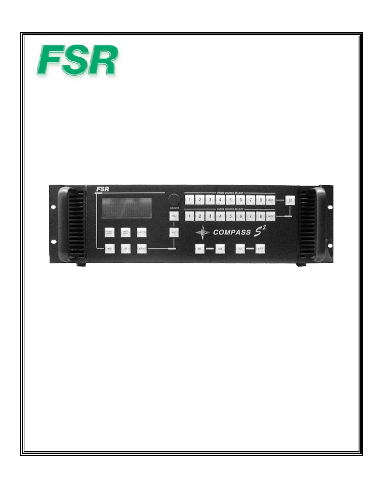
COMPASS S2TM – Audio and Video Seamless Switcher
244 Bergen Boulevard, West Paterson, NJ 07424 • Tel 9737854347 • FAX 9737853318 • Web wwww.fsrinc.com
4/04 43854 LIT1009 A
Model CN-2002
Page 2
COMPASS S2
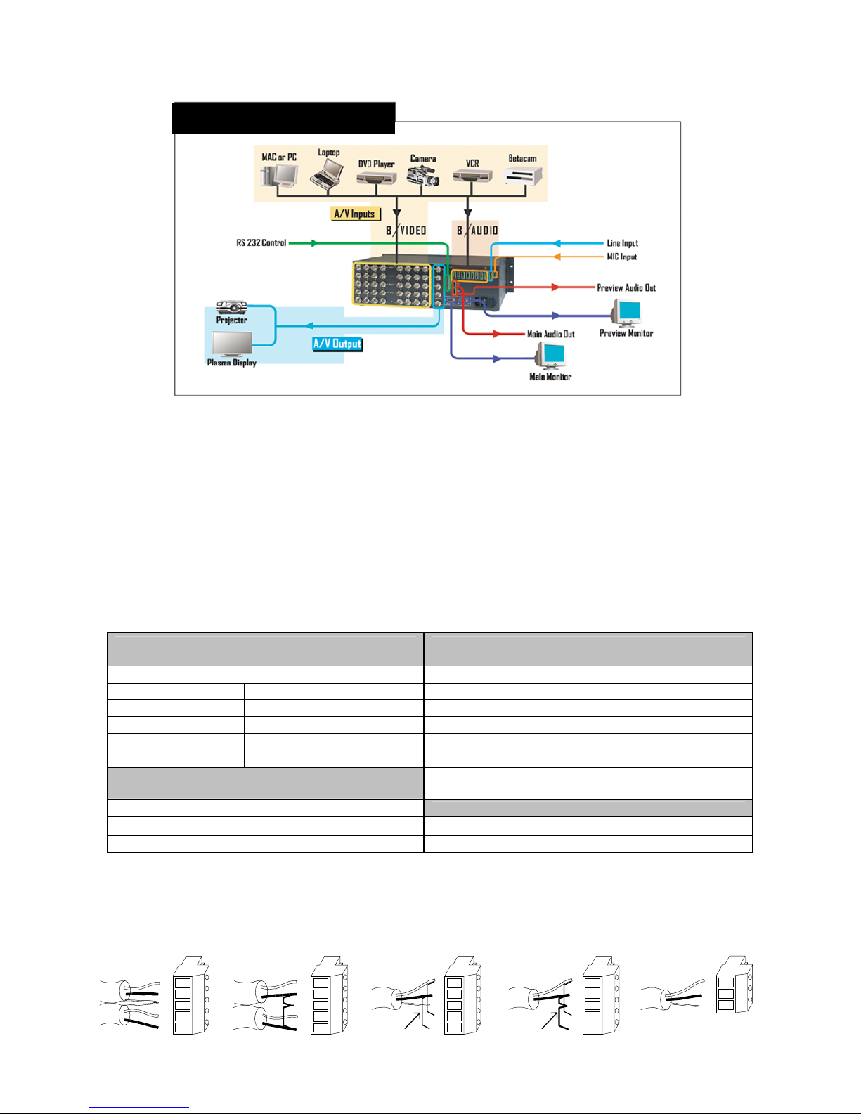
Step 1: Connect Compass S2™ to Output Devices
Connect one of the two available “Main” video outputs to your projector and the “Main” audio output to a set of amplified speakers. Note
that the second main video output may be connected to a local display monitor if the projection screen is not easily viewed by the
operator.
Connect the “Preview” video output to a computer monitor and the “Preview” audio output to a second pair of powered
speakers. (Note: The preview video output timing is identical to the main video output. If the main video output is set to 1280 x 1024,
the preview monitor must be capable of that resolution.)
Step 2: Connect Input Sources to Compass S2™
Compass S2™ has eight universal video inputs that accept composite (NTSC & PAL), S-video, component, and computer video
sources. Connect each type of video input source to Compass S2™ as indicated in the following table:
Compass S2™ has nine audio inputs that accept balanced and unbalanced signals for audio Sources 1 through 8 and a single Line
input. A tenth input accepts several types of microphones. Connect each type of audio input source to Compass S2™ as indicated in
the following diagram:
TM
Quick Start Guide
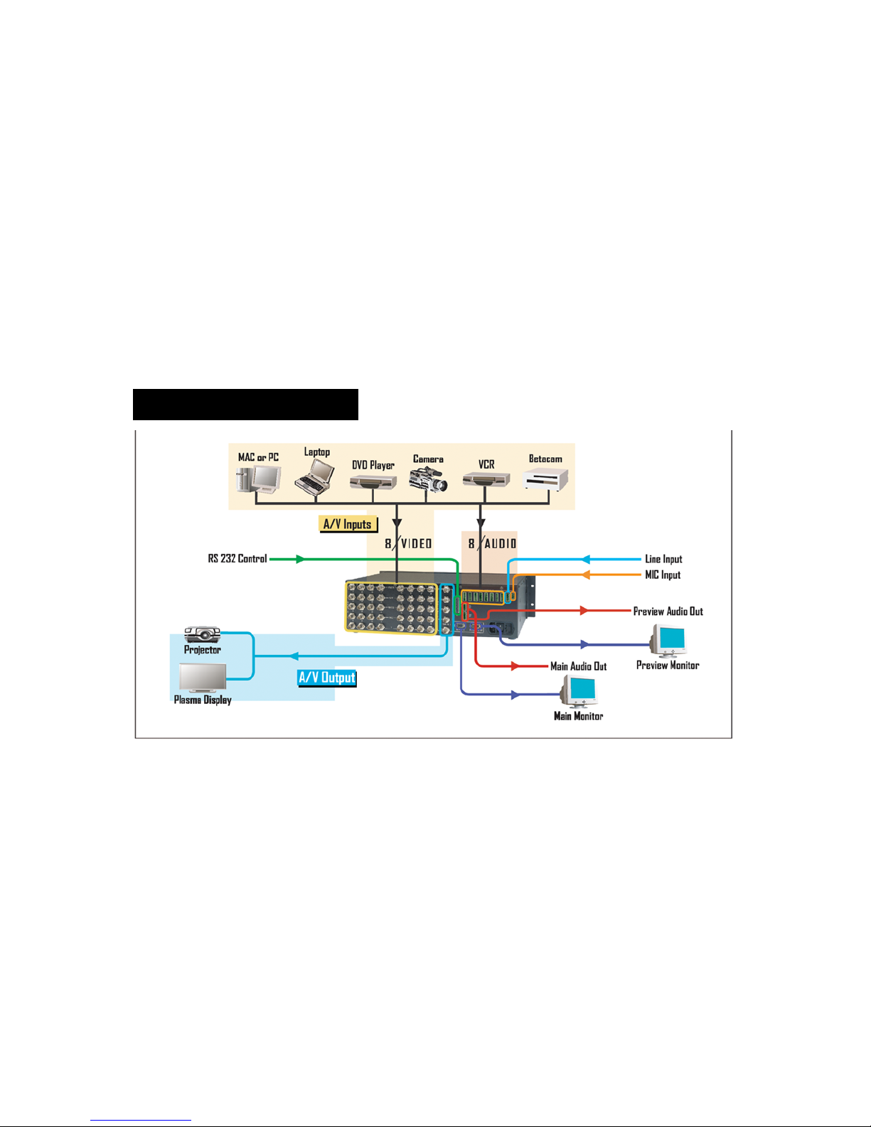
COMPASS S2TM Connectivity Diagram
Illustration of Typical Compass S2™ Setup
Input Connections
Format – RGB
(Typical Devices: Computers)
Source to Compass S2 Source to Compass S2
R R/CR Y G/Y
G G/Y Pr R/CR
B B/CB Pb B/CB
H H/C or
V V Y G/Y
(Typical Devices: S-Video VCR)
Source to Compass S2
Format – Composite/PAL (Typical Devices: NTSC/PAL VCR)
Y G/Y
C B/CB NTSC/PAL G/Y
Format – YUV or Y Pr Pb (Betacam)
(Typical Devices: DVD Player or Betacam Deck)
U R/CR Format – S-Video (Y/C)
V B/CB
Source to Compass S2
Stereo Input Connector Wiring
Balanced Wiring Unbalanced Wirin g
+
L
-
SH
+
R
-
Jumpers
L
SH
R
Mono Input Connector Wiring
Balanced Wiring Unbalanced Wiring
+
+
-
Jumpers
L
SH
R
+
+
-
Jumpers
L
SH
R
+
+
-
Mic Input Connector
Wiring
+
-
SH
Page 3

Step 3: Power Up
Connect Compass S2™ to 115 VAC power using the power cord supplied with the unit. Locate the power switch on the power entry
module at the rear of the unit and turn the power on. The unit will flash all of the front panel illuminated keys in unison, first with red,
then green, and then white. While the main board is initializing, “please wait” will be displayed. The front panel display will show the
main menu which indicates the unit has powered up successfully.
Step 4: Power Up Display
The default power-up condition is to set the video to BLK (black screen input) as the “Main” source, Source 1 as the “Preview” video
source, MUTE as “Main” audio source and Source 1 as the “Preview” audio source. The keys for the video and audio input sources
currently selected for the main outputs will be red. The keys for the video and audio input sources currently selected for the preview
outputs will be green. The remaining source selection keys will be yellow.
Step 5: Source Selection and Dissolve
The user can easily select any of the video and audio input sources as the current preview sources simply by pushing the
corresponding video or audio source select key. Each time a new video and audio preview source is selected, the key for the selected
source will turn green and the video and audio on the preview monitor and speakers will display output video and audio derived from
the newly selected preview source. The currently selected preview source can be dissolved seamlessly to the main output by pressing
the DSLV key. The preview video and audio sources automatically and seamlessly switch to the main video and audio outputs. See the
manual for the “Audio Breakaway” feature.
Step 6: Select Desired Video Output Format
Set the video output from Compass S2™ to match the projector or other display device. Enter the Output Setup menu by depressing the
OUTPUT SETUP key. The OUTPUT SETUP key will turn from white to red. An arrow “>” will be displayed next to “FORMAT.” Press the
“Select” key. A solid block will start to flash in the arrow location. Rotating the encoder dial will scroll through the available output
resolutions. Stop on the desired output resolution and press “Select.” The output is now set to the desired output format. Press the
OUTPUT SETUP key to leave the Output Setup menu.
Step 7: Projector Adjustments
Proper projector setup is critical to optimize the quality of the output image. Once Compass S2’s output is set to match the native
resolution of the projector, the scaling engine in the projector should be disabled. The methods used to disable the internal scaler within
the projector vary from manufacturer to manufacturer. Compass S2’s Output Setup menu allows the user to select test patterns that are
used during projector adjustment. Please consult the operator’s manual for your equipment.
Step 8: Configure Video and Audio Input Sources
Compass S2™ will automatically lock to video applied to the eight universal inputs and will make a “best guess” at the video format
(RGB, YUV, S-Video, NTSC/PAL) and all associated video parameters. While the “best guess” approach generally leads to an
acceptable output image, it is strongly recommended that the user set up a configuration file to precisely define the video and audio
parameters associated with each video and audio input pair before running a show. The use of configuration files provides consistent,
repeatable operation and allows the user to adjust video and audio parameters for each source to optimize image and sound quality.
Up to 64 configuration files can be stored for use. Each time a video or audio source is selected with the Source Selection keys, the
configuration file associated with that source is automatically reloaded.
Setting up input configuration files is simple. Proceed as follows for each input:
1. Select the source you wish to work with as the Preview source.
2. Press the INPUT SETUP menu key. Examine the image on the Preview monitor and adjust the video input parameters as desired.
The Input Setup menu is described in detail in Section 6.5 of the Installation and Operating Manual. Many of the parameters may
require no adjustment, however, be sure that the INPUT TYPE menu item is selected to match the incoming source. Also verify
that the type of sync indicated in the PROCESSING submenu matches the incoming source. Press the AUDIO button and enter
the audio INPUT SETUP menu and adjust the video input parameters as desired.
3. When the input setup parameters have been set as desired, Press the INPUT SETUP button and enter the SAVE AS submenu to
save the setup parameters as a file. The next available file number is automatically shown on the first line of the SAVE INPUT FILE
menu. You can use this file number to create a new file or assign another number. The third line in the menu allows you to assign
an eight-character file name to the file. Entry of a file name is optional. When the file number and name have been entered, select
SAVE to save the configuration. The file is saved and automatically assigned to the source used for the input setup process. The
input configuration file will automatically be recalled for use each time the source is selected.
Page 4

PROPRIETARY INFORMATION
All information in this manual is proprietary to and the property of FSR inc.
This publication is protected by the Federal Copyright Law, with all
rights reserved. No part of this document may be reproduced, transcribed, or
transmitted, in any form or by any means, without prior explicit
written permission from FSR inc.
Page 5
Operators Safety Summary
The general safety information in this summary is for operating personnel.
Do Not Remove Covers or Panels There are no user-serviceable parts within the unit. Removal of the top cover will expose dangerous voltages.
To avoid personal injury, do not remove the top cover. Do not operate the unit without the cover installed
Power Source
or between both supply conductor and ground. A protective ground connection by way of grounding conductor in the power cord is essential for safe
operation.
Grounding the Product
cord into a properly wired receptacle before connecting to the product input or output terminals.
grounding conductor in the power cord is essential for safe operation.
Use the Proper Power Cord
Refer cord and connector changes to qualified service personnel.
Use the Proper Fuse
replacement to qualified service personnel.
Do Not Operate in Explosive Atmospheres
This product is intended to operate from a power source that will not apply more than 230 volts rms between the supply conductors
This product is grounded through the grounding conductor of the power cord. To avoid electrical shock, plug the power
Use only the power cord and connector specified for your product. Use only a power cord that is in good condition.
To avoid fire hazard, use only the fuse having identical type, voltage rating, and current rating characteristics. Refer fuse
To avoid explosion, do not operate this product in an explosive atmosphere.
Terms In This Manual
WARNING Highlights an operating procedure, practice, condition, statement, etc., which, if not strictly observed, could result in injury to or death of
personnel. NOTE Highlights an essential operating procedure, condition or statement.
CAUTION
maintenance (servicing) instructions in the literatureaccompanying the appliance.
AVERTISSEMENT! Le point d´exclamation dans un triangle equilatéral signale à alerter l´utilisateur qu´il y a des instructions d´operation et d´entretien
es importantes dans la litérature qui accompagne l´appareil. tr
The exclamation point within an equilateral triangle is intended to alert the user to the presence of important operating and
VORSICHT ein Ausrufungszeichen innerhalb eines gleichwinkeligen Dreiecks dient dazu,den Benutzer auf wichtige Bedienungs-und
Wartungsanweisungen in der Dem Great beiliegenden Literatur aufmerksam zu machen.
WARNING The rear panel ON/OFF switch does not disconnect the unit from input AC power. To facilitate disconnection of AC power, the power cord
must be connected to an accessible outlet near the unit. Building Branch Circuit Protection: For 115 V use 20 A, for 230 V use 8 A.
WARNING When the COMPASS is used in the 230-volt mode, a UL listed line cord rated for 250 volts at 15 amps must be used and must conform to
IEC-227 and IEC-245 standards. This cord will be fitted with a tandem prong-type plug.
.
A protective-ground connection by way of the
TERMS AS MARKED ON EQUIPMENT
CAUTION Highlights an operating procedure, practice, condition, statement, etc., which, if not strictly observed, could result in injury to or death of
personnel.
CAUTION
maintenance (servicing) instructions in the literatureaccompanying the appliance.
AVERTISSEMENT!
d´entretien tres importantes dans la litérature qui accompagne l´appareil
VORSICHT
Wartungsanweisungen in der Dem Great beiliegenden Literatur aufmerksam zu machen.
NOTE This equipment has been tested and found to comply with the limits for a Class A digital device, pursuant to Part 15 of the FCC Rules. These
limits are designed to provide reasonable protection against harmful interference when the equipment is operated in a commercial environment. This
equipment generates, uses, and can radiate radio frequency energy and, if not installed and used in accordance with the instruction manual, may
cause harmful interference to radio communications. Operation of this equipment in a residential area is likely to cause harmful interference, in which
case the user will be required to correct the interference at the users own expense.
The exclamation point within an equilateral triangle is intended to alert the user to the presence of important operating and
Le point d´exclamation dans un triangle equilatéral signale à alerter l´utilisateur qu´il y a des instructions d´operation et
Ein Ausrufungszeichen innerhalb eines gleichwinkeligen Dreiecks dient dazu, den Benutzer auf wichtige Bedienungs-und
Page 6

Page 7

Table of Contents
CHAPTER ONE ............................................................................................................................................1
Introduction .................................................................................................................................................1
About the Compass S2 .............................................................................................................................................2
Features ....................................................................................................................................................................2
Technical Description ................................................................................................................................................3
CHAPTER TWO ...........................................................................................................................................5
Installation ...................................................................................................................................................5
Rear Panel Connectors .............................................................................................................................................6
Video Input Connections ...........................................................................................................................................6
Rack-Mount Installation.............................................................................................................................................7
Power Cord/Line Voltage Selection...........................................................................................................................7
Video Input Connections ...........................................................................................................................................8
Video Output Connections ........................................................................................................................................8
Main Outputs...........................................................................................................................................................8
Preview Output .......................................................................................................................................................8
Audio Input Connections ...........................................................................................................................................8
Audio and Line Inputs .............................................................................................................................................8
MIC Input ................................................................................................................................................................9
Audio Output Connections ........................................................................................................................................9
Remote Control Connections ..................................................................................................................................10
CHAPTER THREE...................................................................................................................................... 13
Operation ...................................................................................................................................................13
Front Panel Controls ...............................................................................................................................................14
Power-Up Initialization............................................................................................................................................. 15
VIDEO SOURCE SELECT and AUDIO SOURCE SELECT Keys...........................................................................15
A/V SEL Key............................................................................................................................................................15
A/V Follow Mode .....................................................................................................................................................16
A/V Breakaway Mode..............................................................................................................................................16
EFFECTS Keys ....................................................................................................................................................... 16
MIXER Keys............................................................................................................................................................ 16
Menu Operation....................................................................................................................................................... 16
Input Setup Menu—Standard .................................................................................................................................. 17
Active Input ........................................................................................................................................................... 17
Menu Mode ........................................................................................................................................................... 17
Image Size and Position Adjustments................................................................................................................... 17
Contrast/Brightness ..............................................................................................................................................17
Input Type............................................................................................................................................................. 17
Color Balance .......................................................................................................................................................18
Color Balance Submenus .....................................................................................................................................18
Processing ............................................................................................................................................................19
Processing Submenus ..........................................................................................................................................19
Undo Changes ...................................................................................................................................................... 21
Reset Configuration .............................................................................................................................................. 21
Save FN#.............................................................................................................................................................. 21
Save As ................................................................................................................................................................21
Input Setup Menu, Advanced Mode ........................................................................................................................22
1:1 Sampling Overview .........................................................................................................................................22
Auto Config ...........................................................................................................................................................23
H Total ..................................................................................................................................................................23
Phase Main ........................................................................................................................................................... 23
Phase Preview ...................................................................................................................................................... 23
Position (R) ...........................................................................................................................................................23
Width (L) ...............................................................................................................................................................23
Audio Menu .....................................................................................................................
Volume Adjustment Menu ..................................................................................................................................... 23
Audio Input Setup Menu .......................................................................................................................................24
MIC and LINE Setup Menu ................................................................................................................................... 24
Audio Effects Menu...............................................................................................................................................24
Effect Menu .............................................................................................................................................................25
Output Setup Menu ................................................................................................................................................. 25
Output Format....................................................................................................................................................... 25
........................................23
Compass S2 i
Page 8

Frame Rate ........................................................................................................................................................... 25
Sync...................................................................................................................................................................... 25
Test Pattern ..........................................................................................................................................................26
Raster Box ............................................................................................................................................................ 26
File Menu.................................................................................................................................................................26
IN1 – IN8............................................................................................................................................................... 26
Delete A File .........................................................................................................................................................26
Miscellaneous Menu................................................................................................................................................ 26
System Save......................................................................................................................................................... 27
Config Serial .........................................................................................................................................................27
Tech Support Menu ..............................................................................................................................................27
Remote Protocol Menu .........................................................................................................................................27
Backlight Menu ……………………………………………………………………………………………………...27
A/V Mode……………………………………………………………………………………………………………………28
Remote Protocol……………………………………………………………………………………………………………28
Factory Reset Submenu .......................................................................................................................................28
KEYING AND FREEZE 2 NEW FEATURES…………………………………………………………………………… 28
CHAPTER FOUR........................................................................................................................................ 31
Serial & Remote Command Syntax ......................................................................................................... 31
Serial Parameters....................................................................................................................................................32
Serial Command Formats .......................................................................................................................................32
RS232 Mode ......................................................................................................................................................... 32
RS485 Mode ......................................................................................................................................................... 32
Configuration Load and Save .................................................................................................................................. 33
Download CFG .....................................................................................................................................................34
Upload CFG .......................................................................................................................................................... 34
Remote Command Format...................................................................................................................................... 35
Compass S2 Command List/Description................................................................................................................. 36
Terminal Remote Control ........................................................................................................................................52
CHAPTER FIVE.......................................................................................................................................... 53
PM-2002 Software Upgrade Instructions ................................................................................................53
Overview .................................................................................................................................................................54
Hardware Requirements .........................................................................................................................................54
Software Requirements........................................................................................................................................... 54
Downloading Necessary Files ................................................................................................................................. 54
Installing the Flash File Loader and Compass S2 Files........................................................................................... 54
Starting the Flash File Loader Utility........................................................................................................................ 55
Preparing to Upgrade the Compass S2 Unit ...........................................................................................................55
Verifying Communications between the Computer and Compass S2 Unit .............................................................. 55
Uploading Files to the Compass S2 Unit................................................................................................................. 55
CHAPTER SIX ............................................................................................................................................ 57
FSR Information........................................................................................................................................ 57
FSR Warranty..........................................................................................................................................................58
Return Material Authorization (RMA).......................................................................................................................58
APPENDIX.................................................................................................................................................. 59
Technical Specifications .......................................................................................................................... 59
A/V Inputs .............................................................................................................................................................60
Video Output ......................................................................................................................................................... 60
Connectors:...........................................................................................................................................................60
Audio Inputs .......................................................................................................................................................... 60
Audio Outputs ....................................................................................................................................................... 60
User Controls ........................................................................................................................................................ 60
Remote Control.....................................................................................................................................................61
Physical.................................................................................................................................................................61
Input Power........................................................................................................................................................... 61
Environmental ....................................................................................................................................................... 61
ii Compass S
2
Page 9
CHAPTER ONE
Introduction
What you will find in this chapter…
About the Compass S2
Features
Technical Description
1
Compass S2 1
Page 10

Introduction
About the Compass S2
Compass S2 is an Audio/Video seamless switcher designed specifically for Systems Integrators. The unit provides
truly seamless transitions to support professional quality audiovisual presentations. Compass S2 features eight
universal A/V inputs that accept composite (NTSC/PAL), s-video, component, computer, and HDTV video as well as
associated stereo audio signals. FSR’s Auto Signal Lock (ASL™) technology simplifies setup by automatically locking
to the incoming video signal and scaling to the native resolution or “sweet spot” of the display device to optimize
image quality. The operator can seamlessly transition between video sources. Audio sources can be configured to
automatically follow video source selection or can be switched independently (audio breakaway with cross-fade).
Compass S2 also accepts two non-switched audio sources (LINE and MIC) that can be mixed with the audio from the
selected input channel. Main and Preview A/V outputs are provided. An RS-232 serial interface is provided to support
remote control operation.
Features
The Compass S2 provides the following features:
• Eight universal A/V inputs accept composite (NTSC/PAL), s-video, component (RGB, Betacam (Y, Pb, Pr)),
and computer video sources with resolutions up to 1600x1200. HDTV 480p, 720p, and 1080i formats are
supported in RGB color space
• FSR’s Auto Signal Lock (ASL
the native resolution or “sweet spot” of the projection or display device
• Advanced audio features; Audio Breakaway, Audio Cross-Fade, and Programmable Audio Delay
• Eight stereo audio inputs (one for each A/V input channel) accept Consumer or Professional audio levels
• Re-configurable RS-232 port for remote control; Crestron Controller Compatible
• 30 user-selectable output formats
• High-performance dual-scaler architecture supports seamless switching
• Motion adaptive de-interlacing
• Two non-switched audio inputs (MIC and LINE) can be mixed with audio from the selected input channel
• Professional quality transition effects include cut and dissolve
• Six test patterns for projector set up
• Main and Preview Outputs
• Ethernet Control (option)
• Backed by a full 3-year parts and labor warranty
™
) technology automatically locks to the selected source and scales it to match
2 Compass S
2
Page 11
Technical Description
Compass S2 is a fully integrated system that simplifies the task of supporting professional-quality audio-visual
presentations. The unit combines an eight input A/V router, two high-performance video scalers, an audio processor,
and a full-featured control panel in a single integrated package. Eight universal A/V inputs accept composite video, svideo, component, computer and video sources with HDTV timing, as well as associated stereo audio signals. The
unit also accepts two non-switched audio sources (LINE and MIC) that can be mixed with the audio from the selected
input channel. The input video is converted directly to the native resolution or "sweet spot" of the projection device to
optimize image quality. Compass S2 supports seamless transitions including cut and dissolve effects when sources
are switched.
The Compass S2 provides two independently buffered Main video outputs and one Preview video output. The
presentation viewed by the audience is provided via the Main outputs. The Preview output is provided to allow the
operator to examine the next audio/video source to be displayed. The Compass S2 user interface has been designed
with intuitive, user-friendly menus to simplify system setup and adjustment. User-defined configuration files can be
created, stored, recalled, and edited.
A connectivity diagram for the unit is provided below.
COMPASS S2TM Connectivity Diagram
Compass S2 3
Page 12

Page 13
CHAPTER TWO
Installation
What you will find in this chapter…
Rear Panel Connectors
Rack-Mount Installation
Power Cord/Line Voltage Selection
Video Input & Output Connections
Audio Input & Output Connections
RS-232 Remote Control Connections
2
Compass S2 5
Page 14
Installation
Rear Panel Connectors
NOTE: Front Panel features are shown in Chapter 3.
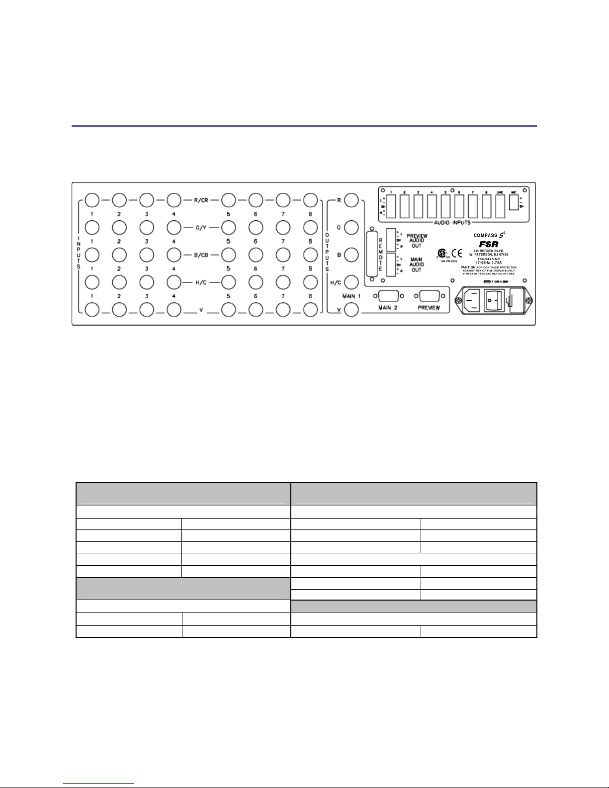
Figure 2-1: Compass S2 Rear Panel
Video Input Connections
The video input section on the Compass S2 rear panel provides eight universal inputs. Each input can accept
composite (NTSC/PAL), s-video, component (RGB, Betacam (Y, Pb, Pr)), and computer video signals. The
connections for each input channel are made via five BNC connectors. Connection points for each type of video
signal are specified below.
Format – RGB
(Typical Devices: Computers)
Source to Compass S2 Source to Compass S2
R R/CR Y G/Y
G G/Y Pr R/CR
B B/CB Pb B/CB
H H/C or
V V Y G/Y
(Typical Devices: S-Video VCR)
Source to Compass S2
Y G/Y
C B/CB NTSC/PAL G/Y
Format – Composite/PAL (Typical Devices: NTSC/PAL VCR)
Format – YUV or Y Pr Pb (Betacam)
(Typical Devices: DVD Player or Betacam Deck)
U R/CR Format – S-Video (Y/C)
V B/CB
Source to Compass S2
6 Compass S
2
Page 15
Rack-Mount Installation
Compass S2 units are designed to be rack mounted and are supplied with front rack-mount hardware. Rear rackmount brackets are available as a kit and are recommended for use when units are mounted in transit cases. When
rack mounting the unit, remember that maximum ambient operating temperature for the unit is 40 degrees C. Leave
at least one inch of space on each side and at the front of the unit to make sure that the airflow through the fan and
vent holes is not restricted. When installing equipment into a rack, distribute the units evenly to prevent hazardous
conditions that may be created by uneven weight distribution. Connect the unit only to a properly rated supply circuit.
Reliable grounding (earthing) of rack-mounted equipment should be maintained.
Power Cord/Line Voltage Selection
Compass S2 is rated to operate with the following supplies:
Input Power: 85-264 VAC, 47-63 Hz
Power Consumption: 175 watts maximum
The Compass S2 performs line voltage selection automatically. No user controls are required for line voltage
selection.
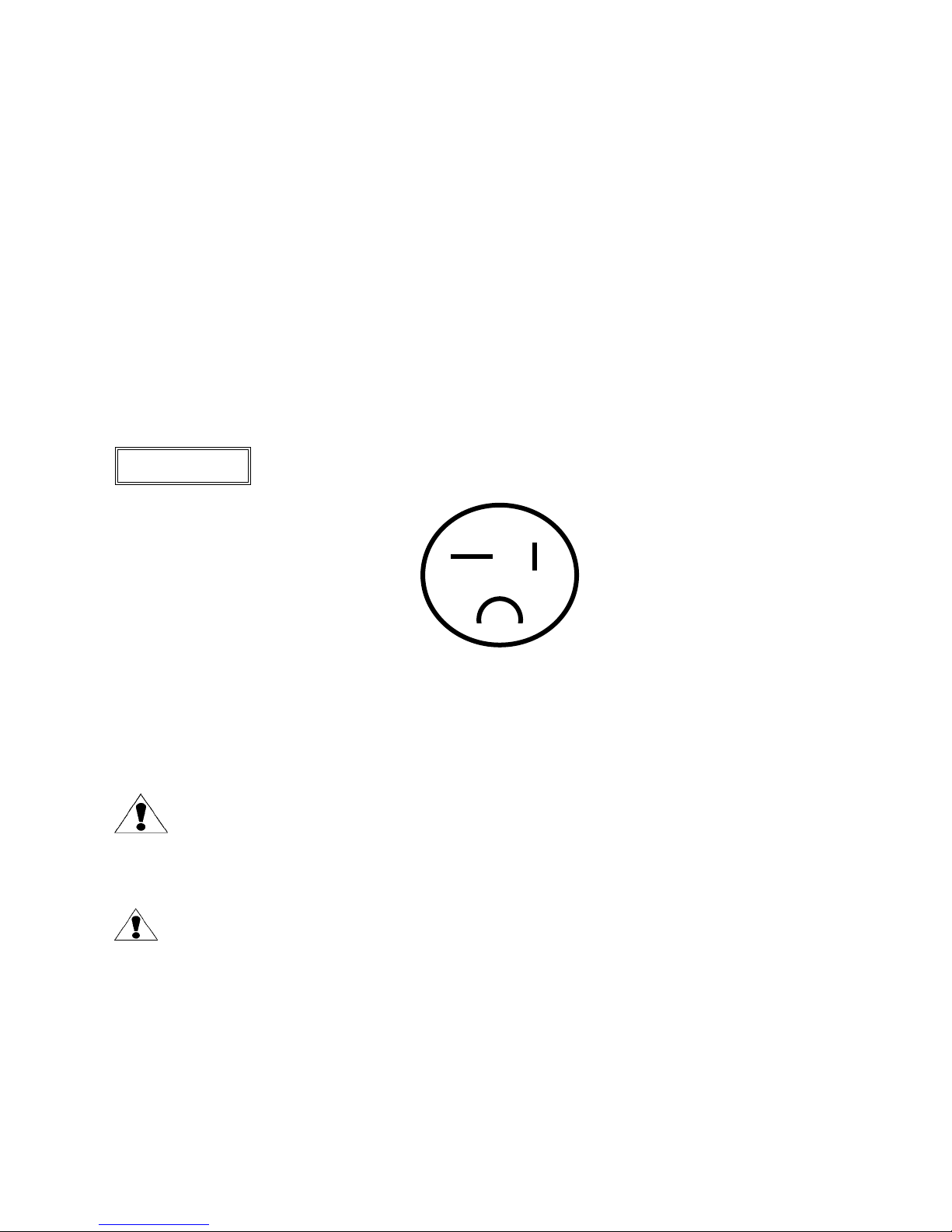
WARNING
When the Compass S2 is used with 230-volt supplies, a UL listed line cord rated for 250
volts at 15 amps must be used. This cord will be fitted with a tandem prong-type plug.
Figure 5-2: Tandem Plug
AVERTISSEMENT!
VORSICHT
La choix de la ligne de voltage se realize automatiquement par I’Compass S2
Transformateur Graphique On n’apas besoin du controller usager pour la choix de la ligne
de voltage.
Das Compass S2-Gerät mu beim Anschlu an 240V ~ mit einer vom VDE auf 250V/10A geprüften
Netzleitung mit einem Schukostecker ausgestattet sein.
Compass S2 7
Page 16
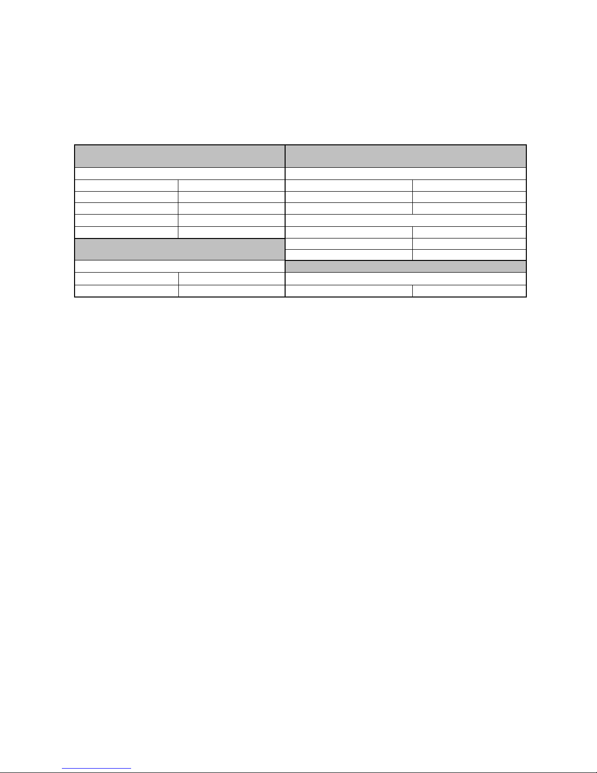
Video Input Connections
The video input section on the Compass S2 rear panel provides eight universal inputs. Each input can accept
composite (NTSC/PAL), s-video, component (RGB, Betacam (Y, Pb, Pr)), and computer video signals. The
connections for each input channel are made via five BNC connectors. Connection points for each type of video
signal are specified below.
Format – RGB
(Typical Devices: Computers)
Format – YUV or Y Pr Pb (Betacam)
(Typical Devices: DVD Player or Betacam Deck)
Source to Compass S2 Source to Compass S2
R R/CR Y G/Y
G G/Y Pr R/CR
B B/CB Pb B/CB
H H/C or
V V Y G/Y
U R/CR Format – S-Video (Y/C)
(Typical Devices: S-Video VCR)
Source to Compass S2
Format – Composite/PAL (Typical Devices: NTSC/PAL VCR)
Y G/Y
V B/CB
Source to Compass S2
C B/CB NTSC/PAL G/Y
Video Output Connections
Main Outputs
Two independently buffered Main outputs (one five wire BNC connection and one HD-15) are provided. Either of
these outputs may be used to connect to the display device used for the presentation. The second output is designed
to support a local display in the event that the operator is unable to conveniently view the presentation. Both outputs
provide RGB video signals. The operator can select the type of output sync to match application requirements (see
Output Setup Menu, page 25). Separate C (Composite) or separate H/V (Horizontal/Vertical) sync modes are
supported.
Connect the outputs labeled R,G, and B on the rear panel of the Compass S2 unit to the correspondingly labeled
connectors on the output device. Connect the C or H/V sync signals from Compass S2 to the correspondingly labeled
connectors on the output device. If separate H/V sync mode is being used, be sure to connect both the H and V
signals.
Preview Output
One Preview output is provided on an HD-15 connector. The Preview output is provided to permit the operator to
view the next source video to be displayed prior to initiating a transition. The Preview output provides an RGB video
signal. Connect the output on the rear panel of the Compass S2 unit to the output device.
The operator can select the type of output sync to match application requirements (see Output Setup Menu, page
25). Separate C (Composite) or separate H/V (Horizontal/Vertical) sync modes are supported. Connect the C or H/V
sync signals from Compass S2 to the correspondingly labeled connectors on the output device. If separate H/V sync
mode is being used, be sure to connect both the H and V signals.
Audio Input Connections
Audio and Line Inputs
Each video input (1 – 8) has an associated stereo audio input. Mating connectors are provided with the unit to
facilitate connection of the audio inputs. The wiring for the connectors is illustrated below:
8 Compass S
2
Page 17
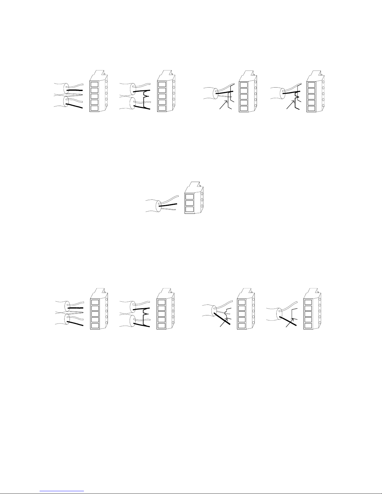
Input Connect or Wiring
Stereo Input Connector Wiring
Balanced Wiring Unbalanced Wiring
Mono Input Connector Wiring
Balanced Wiring Unbalanced Wiring
Jumper
L
SH
R
+
-
+
Jumpers
L
SH
R
+
-
+
Jumpers
L
SH
R
+
-
+
-
L
SH
R
+
-
+
-
MIC Input
The MIC Input is a non-switched input designed to accept input from a microphone. The MIC Input may be mixed with
audio from the selected A/V source as well as the Line Input. Mating connectors are provided with the unit to facilitate
connection of the MIC Input. Connector wiring is shown below:
MIC Input Connector Wiring
+
-
SH
Audio Output Connections
Main and Preview stereo audio outputs are provided. Mating connectors are provided with the unit to facilitate
connection of output devices. Wiring of the connectors is illustrated below:
Output Connector Wiring
Strereo Output Connector Wiring
Balanced Wiring Unbalanced Wir i ng
Jumper
L
SH
R
+
-
+
-
SH
R
+
L
-
+
-
Mono Output Connector Wiring
Balanced Wiri n g Unbalanced Wiring
L
SH
R
+
-
+
-
Jumper
L
SH
R
+
-
+
Jumper
Compass S2 9
Page 18
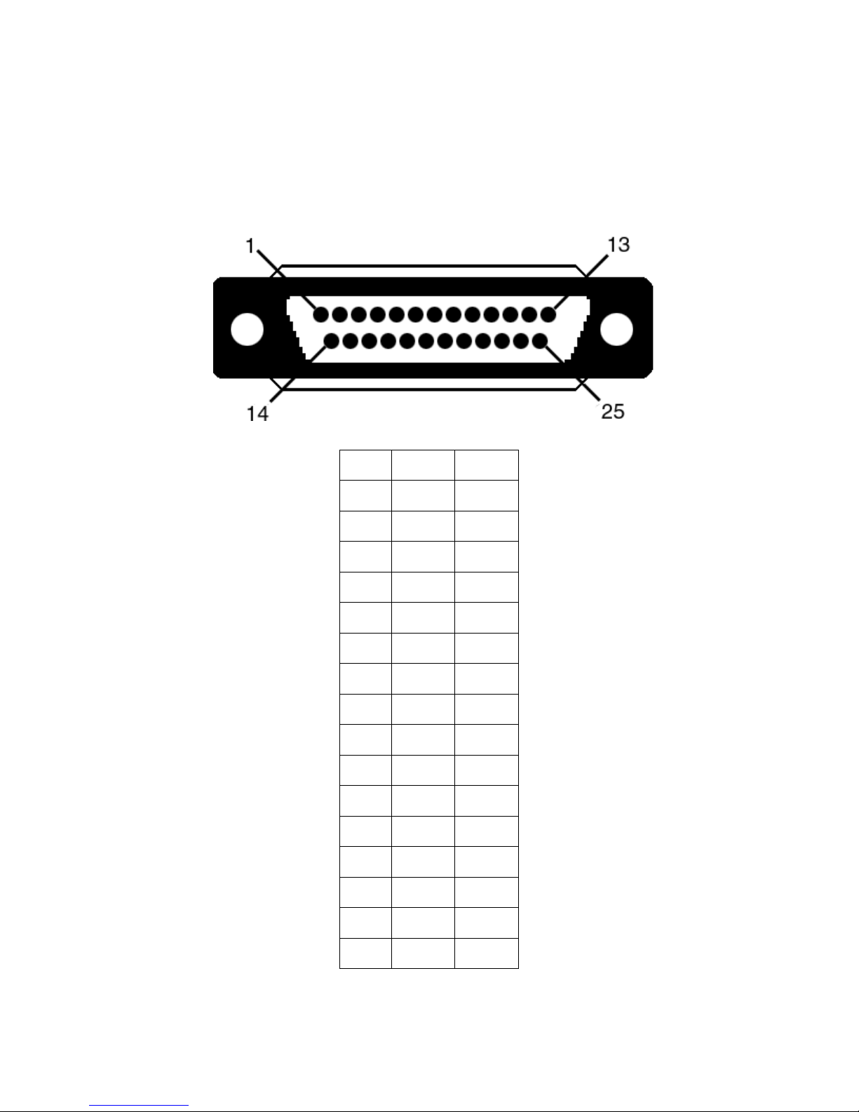
Remote Control Connections
The serial port can be connected to a computer to support remote control of the Compass S2 unit with either RS232
or RS485 hardware protocols. Connection points on the remote port connector are specified below.
REMOTE
DB25 RS232 RS485
1 Shield Shield
2 TxD T(-)
3 RxD R(-)
4 RTS N/A
5 CTS N/A
6 DSR N/A
7 Sig Gnd Sig Gnd
8 DCD N/A
10 N/A N/A
12 N/A N/A
14 N/A T(+)
15 N/A N/A
16 N/A R(+)
19 N/A N/A
20 DTR N/A
10 Compass S
21-25 N/A N/A
2
Page 19

Compass S2 11
Page 20

Page 21
CHAPTER THREE
Operation
What you will find in this chapter…
Description of Front Panel Controls
Power-Up Initialization
Menu Operation
3
Compass S2 13
Page 22
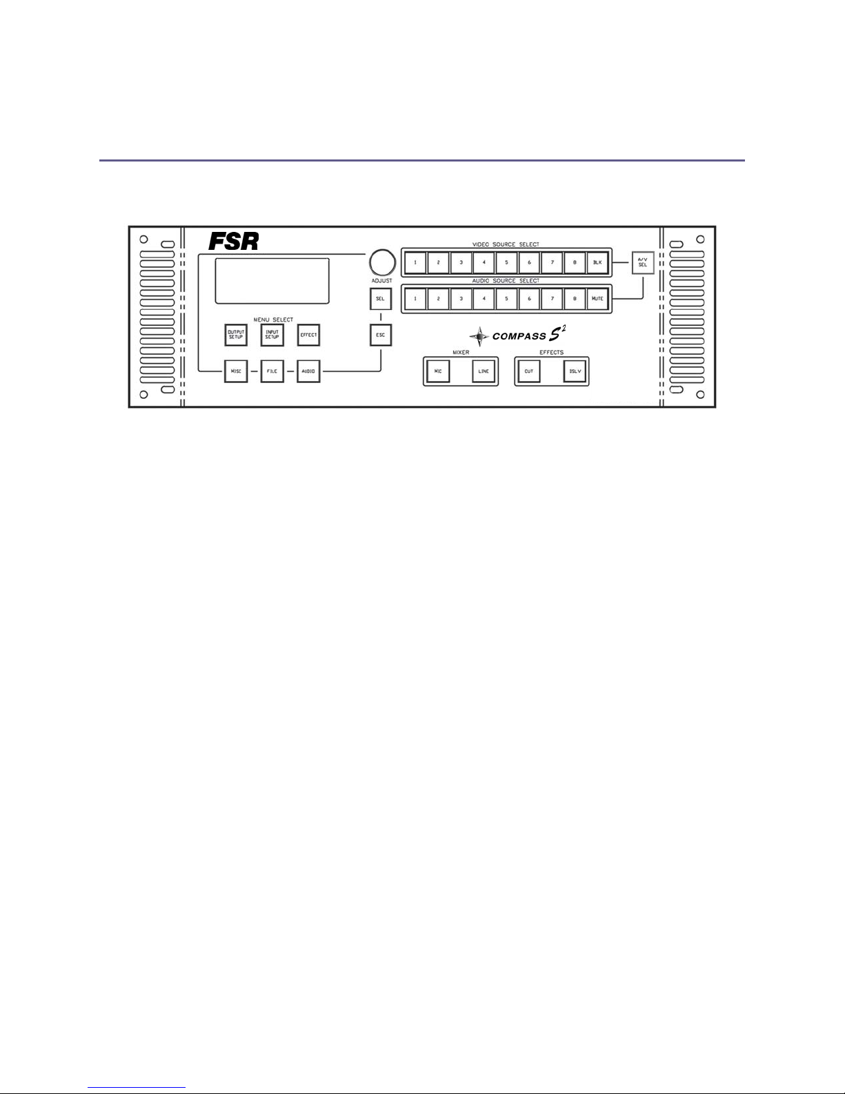
Operation
Front Panel Controls
NOTE: Rear Panel features are shown in Chapter 2.
Figure 3-1 Compass S2 Front Panel
14 Compass S
2
Page 23
Power-Up Initialization
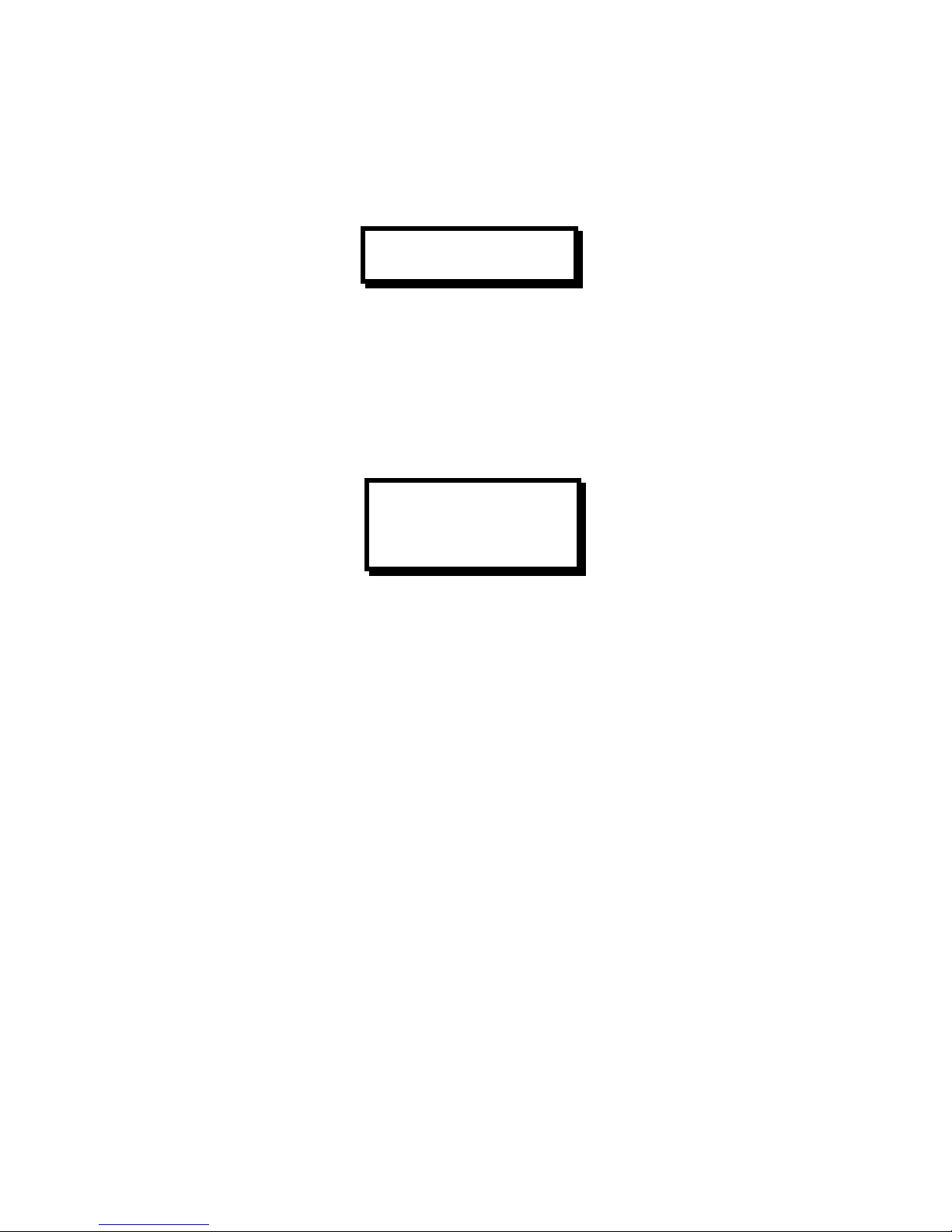
Locate the power switch on the rear panel and turn Compass S2 on. While Compass S2 is initializing: “Please
Wait…” displays for 30 seconds then the front panel indicators will cycle red, green, and yellow. The following menu
will then display for a few seconds.
This text indicates the version of software that is currently being loaded. The software version number will change as
software upgrades are released. The most current software version is available for download from the FSR
The main menu displays commonly referenced information for the currently selected Main and Preview audio and
video channels. Active Main and Preview audio and video channels are indicated, as are the currently loaded input
setup filenames. Video dissolve time, audio/video switching mode, microphone, and line active states are also
indicated. The startup main menu appears as follows:
This menu indicates the startup state for the Compass S2. The main video output is set to black with the audio output
muted. Preview outputs are set for channel one on both video and audio. No input setup files are loaded on main or
preview. The video dissolve time is 1.0 seconds, audio/video “Follow” mode is active and the Line output is active on
both the main and preview audio outputs. Note that when the microphone is active on the main audio output, an M is
displayed to the left of the L.
The power-up state of the keys corresponds to the main menu display. The preview audio and video source selection
“1” keys will light green, while the main source selection keys BLK and MUTE light red. The A/V SEL key lights green
to indicate “Follow” mode and the LINE key lights green to indicate that the audio line source is active on the main
audio output.
Compass S2
3.03 0 A
MAIN PREVIEW
Black Empty
BLK/MUTE 1/1
1.0 -Follow- L
VIDEO SOURCE SELECT and AUDIO SOURCE SELECT Keys
The user can easily select any of the input video sources as the current Preview source simply by pushing the
corresponding AUDIO or VIDEO SOURCE SELECT key. Each time a new Preview source is selected, the key for the
selected source will turn green and the Preview output will change to the newly selected source.
Buttons 1 through 8 are used to select the eight different input sources. The MUTE or BLK key can be selected to
provide a muted audio or black video source for fade transitions.
The keys for the audio/video sources currently active on the Main output will be red. The keys for the source currently
selected for the Preview output will be green. The remaining source selection keys will be yellow. The default powerup condition is to set MUTE audio and BLK video (black screen input) as the Main source and Source 1 as the
Preview source.
A/V SEL Key
The A/V SEL key toggles between audio “Follow” mode and audio “Breakaway” mode. In audio “Follow” mode, the
A/V key lights green, whereas in audio “Breakaway” mode, the key lights yellow.
Compass S2 15
Page 24

A/V Follow Mode
This mode provides simple audio/video switching from either the audio source select keys or the video source select
keys. If a key from either bus is selected, the corresponding key on the other bus will “follow” and light green. Any
transition effected in this mode will be performed on both buses identically, with both audio and video transitioning in
the same manner for the same amount of time.
A/V Breakaway Mode
Audio “breakway” mode separates audio and video selections and transitions. A selection from one of the video
source select keys will not affect the audio source select bus in any way. Only a selection from the audio source
select keys will effect a change of the audio preview output. In this mode, audio can be switched and transitioned
without video selection or transition. Also in this mode, video can be switched and transitioned without audio selection
or transition. Thus this mode separates the two selection buses and sources so they can be controlled independently.
EFFECTS Keys
The currently selected Preview source can be transitioned seamlessly to the Main output using one of the EFFECTS
keys. After selecting a Preview source, simply press either CUT or DSLV. The Preview source will automatically and
seamlessly switch to the Main output. Dissolve duration in audio/video “Follow” mode is programmed via the EFFECT
menu between 0.0 and 5.0 seconds.
MIXER Keys
Two non-switched audio inputs, MIC and LINE, can be mixed with audio from the selected input channel. When a
MIXER indicator is green, the mixer source is active on both Main and Preview. A mixer source is disabled when it’s
indicator is yellow.
Menu Operation
The Menu Select keys are used to activate menus used to configure the unit for operation. Pressing one of the six
Menu Select keys will call up the corresponding menu on the display. The operation of each menu is described in
detail in the following sections of this document.
Once a menu is selected with the Menu Select keys, the Adjust control is used to scroll through the menus items. As
the user scrolls through the menu items, a pointer at the left of the menu indicates the current position of the scroll
bar. When the user reaches the menu item that needs to be changed, the Select key is used to select the menu item.
The pointer at the left hand side of the display changes to a # symbol to indicate when a menu item is selected. The
Adjust control can then be used to change the parameters associated with the menu item. When the desired
parameter has been selected, the operator presses the Select key to enter the new values. The menu parameters are
changed and the menu returns to scrolling mode.
The ESC key is used to return to scrolling mode without entering any changes made to a menu item. When this key is
used, changes made to the selected menu item are discarded rather than entered as described for the Select key
above.
16 Compass S
2
Page 25

Input Setup Menu—Standard
INPUT SETUP 1
ACTIVE PREVIEW
MENU MODE STANDARD
RIGHT EDGE
LEFT EDGE
TOP EDGE
BOTTOM EDGE
CONTRAST 100.0%
BRIGHTNESS 100.0%
INPUT TYPE S-VIDEO
COLOR BAL >>
PROCESSING >>
UNDO CHANGES
RESET CONFIG
SAVE FN #
SAVE AS >>
Active Input
The first line in the menu is used to select whether adjustments will be made for the video assigned to the Main or
Preview outputs. The default selection is Preview as this allows adjustments to be made during a show without
impacting the Main display. The number of the input channel corresponding to the selected active input is indicated at
the top right corner of the menu.
Menu Mode
There are two menu modes, Standard and Advanced. The Standard menus are sufficient for most users. The
Advanced menus provide controls for 1:1 pixel sampling features to optimize image quality for critical applications.
Image Size and Position Adjustments
The Right Edge, Left Edge, Top Edge, and Bottom Edge parameters allow the operator to adjust the size and position
of the image. To perform adjustments, scroll to the appropriate menu item with the Adjust control, select the menu
item with the Select key, and then turn the Adjust control to adjust the position of the selected edge of the image
while viewing the active screen. The menu will show ‘+’ or ‘-’ depending on which direction the Adjust control is being
turned. Press Select again to enter the new settings or ESC to exit without accepting the changes that have been
input.
Contrast/Brightness
The Contrast and Brightness controls allow the operator to adjust the overall contrast and brightness of the image. To
perform adjustments, scroll to the appropriate menu item with the Adjust control, select the menu item with the Select
key and then turn the Adjust control to perform adjustments while viewing the active screen. The adjustment range is
75.0% to 125.0%. Press Select again to enter the new settings or ESC to exit without accepting the changes that
have been input.
Input Type
The Input Type menu item allows the operator to select settings for a specific type of input video. Selection options
are S-video, RGB, Beta 50, Beta 60, MII, EBU and Composite (NTSC/PAL). Compass S2 will attempt to determine
the type of input video on the selected input channel and will initially choose the format. The Input Type menu allows
the operator to override the selections in the event that an error is made (it is sometimes difficult to automatically
distinguish between modes as input image content is unknown). To perform adjustments, scroll to the Input Type
menu, select the menu item with the Select key and then turn the Adjust control to select the desired format while
viewing the active screen. Press Select again to accept the newly entered settings or ESC to exit without accepting
Compass S2 17
Page 26

the changes that have been input.
Color Balance
The Color Balance menu line is used to call up a submenu where color balance adjustments are performed. Scroll to
the Color Balance submenu line and press the Select key to display the Color Balance submenu. The Color Balance
menu corresponding to the current contents of the Input Type field (directly above this menu field) will be displayed.
Color Balance Submenus
There are 3 different types of Color Balance submenus as described below. Each submenu corresponds to a specific
type of input video as selected in the Input Type field of the Input Setup menu.
RGB Color Balance Submenu
This menu allows the operator to balance the colors on an RGB input source. Independent Contrast and Brightness
adjustments are provided for each color channel. Parameters entered by the operator are saved as part of the input
configuration file for the corresponding video input channel.
To perform adjustments, scroll to the desired menu line, select the menu item with the Select key and then turn the
Adjust control to select the desired contrast or brightness level while viewing the active screen. Press Select to
accept the newly entered settings or ESC key to exit without accepting the changes that have been entered. The
adjustment for Brightness and Contrast is -25.0% to +25.0%.
The Reset All menu item is used to reset all the fields in this sub menu to the default values (0%). To reset the color
balance controls, scroll to the Reset All menu line and select the menu item with the Select key.
COLOR BALANCE RGB
R CONTRAST 0.0%
R BRIGHTNESS 0.0%
G CONTRAST 0.0%
G BRIGHTNESS 0.0%
B CONTRAST 0.0%
B BRIGHTNESS 0.0%
RESET ALL
S-Video or Composite Video Color Balance Submenu
This menu allows the operator to balance the colors on an S-video or Composite (NTSC/PAL) input source.
Independent Saturation and Hue adjustments are provided. Parameters entered by the operator are saved as part of
the input configuration file for the corresponding video input channel.
To perform adjustments, scroll to the desired menu line, select the
menu item with the Select key and then turn the Adjust control to select the desired saturation or hue level while
18 Compass S
ENC COLOR BALANCE
SATURATION 100.0%
HUE (DEGREES) 0°
R CONTRAST 0.0%
R BRIGHTNESS 0.0%
G CONTRAST 0.0%
G BRIGHTNESS 0.0%
B CONTRAST 0.0%
B BRIGHTNESS 0.0%
RESET ALL
2
Page 27

viewing the Preview screen. Press Select to accept the newly entered settings or ESC key to exit without accepting
the changes that have been entered. The adjustment range for saturation is 75.0% to 125.0%. Hue is adjustable in 1
degree increments from 0 to 360 degrees.
Red, Green and Blue Contrast and Brightness adjustments range from –25.0% to 25.0% in 0.1% increments.
The Reset Color menu item is used to reset all the fields in this sub menu to the default values. To reset the color
balance controls, scroll to the Reset Color menu line and select the menu item with the Select key. The saturation
parameter will be reset to 100.0% and the HUE field will be reset to 0 degrees.
Beta 50, Beta 60, MII, and EBU Color Balance Submenus
This menu allows the operator to adjust saturation on Beta 50, Beta 60, MII, and EBU input sources. Parameters
entered by the operator are saved as part of the input configuration file for the corresponding video input channel.
To perform adjustments, scroll to the Saturation menu line, select the menu item with the Select key and then turn the
Adjust control to select the desired saturation level while viewing the Preview screen. Press Select to accept the
newly entered settings or ESC key to exit without accepting the changes that have been entered. The adjustment
range for saturation is 75.0% to 125.0%. Red, Green and Blue Contrast and Brightness adjustments range from –
25.0% to 25.0% in 0.1% increments.
The Reset All menu item is used to reset all the fields in this sub menu to the default values. To reset the saturation
controls, scroll to the Reset All menu line and select the menu item with the Select key. The saturation parameter will
be reset to 100.0%.
BETA COLOR BALANCE
SATURATION 100.0%
R CONTRAST 0.0%
R BRIGHTNESS 0.0%
G CONTRAST 0.0%
G BRIGHTNESS 0.0%
B CONTRAST 0.0%
B BRIGHTNESS 0.0%
RESET ALL
Processing
The Processing menu line is used to call up a submenu to control input sync selection, DC restoration and deinterlace functions. Scroll to the Processing menu line and press the Select key to display the Processing submenu.
Processing Submenus
The Processing menu line is used to call up a submenu. Scroll to the Processing menu line and press the Select key
to display the Processing submenus.
Compass S2 19
PROCESSING
SYNC SELECT AUTO
DC RESTORE PRCH
DE-INTERLACER DIS/EN
3:2 SEQ DET DIS
VID BW FULL
VID PEAKING MIN
Page 28

20 Compass S
2
Page 29

Sync Select
The Sync Select menu item allows the user to select one of four different modes (Auto, H/V, Comp or SOG). In Auto
Mode, the unit will examine the incoming sync signals and automatically select the active sync source. Auto is the
normal default setting. The user can select H/V (separate H and V sync), Comp (separate Composite sync), or SOG
(Sync-On-Green) modes to override the automatic sync selection. This is sometimes desirable if the input signals are
noisy.
DC Restore
The DC Restore menu item allows the user to select one of three DC Restoration modes (PRCH, PDLY or SYNC).
The default mode is DC Restoration to the back porch of the incoming video signal (PRCH). The PDLY Mode is used
when a tri-level sync comes in on the input, such as an HDTV signal. The SYNC Mode selects DC Restoration to the
sync interval and may be useful for videos without a back porch interval.
De-Interlacer
The De-Interlacer should be on for optimal performance with full-motion video. When the De-Interlacer is enabled, the
video processing of an NTSC format introduces a delay of approximately 3.5 field periods, or 58 ms, between video
input and video output. The De-Interlacer can be disabled by selecting Disable.
3.2 Seq Detect
This menu item is applicable only for standard video (component, s-video, composite) inputs. The default mode is off.
The 3:2 Sequence Detect feature should be turned on to process video derived from film source material.
Video Bandwidth
This menu item is applicable only for S-Video and Composite video inputs. The default mode is Full. The Reduced
setting can be used to soften the image by reducing horizontal bandwidth.
Video Peaking
This menu item is applicable only for S-Video and Composite video inputs. The default mode is normal. Increased
Video Peaking can be obtained by selecting the Increased or Maximum settings. Reduced peaking is obtained by
selecting the Minimum setting.
Undo Changes
The Undo Changes menu item allows the user to undo all changes made since entering the Input Setup Menu. Scroll
to the Undo Changes menu line and press the Select key to undo all changes and return to the Main menu.
Reset Configuration
The Reset Configuration menu item is used to force Compass S2 to ignore Input Setup configuration information
previously entered by the user. When this function is activated the unit will perform an analysis of the input video to
derive and enter new input video default values. To activate this function, scroll to the Reset Configuration menu line
and press the Select key.
Save FN#
This menu item provides quick one-button update operation. The input configuration file name and number (FN#)
associated with the source selected for calibration is shown on the menu line. To replace the selected file, simply
scroll down to the SAVE menu item and press the Select key. The contents of the selected input configuration file will
be replaced with the current parameter settings. Note that if no file has been entered, a default file number and name
will be assigned. The configuration file is automatically recalled each time the source is selected.
Save As
The function of the Save As command is similar to the Save command, however, the Save As command allows the
user to specify a file number and file name.
The Save As menu line is used to save the input setup parameters as a configuration file. The configuration file being
stored is automatically associated with the source used for the input setup process and recalled each time that
source is selected. Scroll to the Save As menu line and press the Select key to display the Save Input File submenu,
as illustrated below.
Compass S2 21
Page 30

The next available file number is automatically shown on the first line of the SAVE INPUT FILE menu. You can use
this file number to create a new file or assign another number (1 • ## • 64). The third line in the menu allows you to
assign an eight-character file name to the file. Use the Select and Adjust controls to select characters to create the
desired file name. Entry of a file name is optional. When the file number and name have been entered, select SAVE
to save the current input configuration to a file. This will overwrite a file previously stored with the same file number.
The file’s input configuration is immediately applied to its associated source.
SAVE INPUT FILE
FILE NUMBER 1
FILE NAME EMPTY
SAVE
Input Setup Menu, Advanced Mode
When the Input Setup key is pressed and the Advanced Menu Mode is selected. The Input Setup Menu will appear
as illustrated below. Menu items that differ from the standard Input Setup Menu are in bold print.
The Advanced Input Setup Menu is intended for use by experienced operators only. This menu allows the user to
configure the unit for 1:1 Pixel Sampling to provide the highest possible image quality. 1:1 Pixel Sampling provides
optimal image quality when properly adjusted; however, improper adjustment may produce an inferior image to what
is obtained with the Standard Input Setup Menu.
INPUT SETUP 1
ACTIVE PREVIEW
MENU MODE ADVANCED
AUTO CONFIG
H TOTAL 1750
PHASE MAIN 0
PHASE PREVIEW 0
POSITION (R) 40
WIDTH (L) 1327
TOP EDGE
BOTTOM EDGE
CONTRAST 100.0%
BRIGHTNESS 100.0%
INPUT TYPE S-VIDEO
COLOR BAL >>
PROCESSING >>
UNDO CHANGES
RESET CONFIG
SAVE FN #
SAVE AS >>
1:1 Sampling Overview
In order to scale an image it must first be digitized. This is the process of changing the analog graphics signals (Red,
Green, and Blue for example) into pixels stored in the Compass S2’s image memory. The default mode of the
Compass S2 is to over sample the input image producing more samples than there are in the original source
material. The over sampled image is then scaled to the final output resolution.
An approach called 1:1 Sampling produces a superior image by sampling the analog graphics signals at exactly the
same rate as that of the original source. This allows the image to be reconstructed with the reduced digitizing
artifacts. The 1:1 Sampling approach requires very accurate settings and even a small sampling error causes noise
on the output image. Both the sample clock frequency and phase must be correct to obtain a properly sampled
22 Compass S
2
Page 31

image. Compass S2 incorporates automatic adjustments in the 1:1 Sampling mode.
Auto Config
To automatically set-up for 1:1 Pixel Sampling, the input image should have non-black data at the edges and have
some amount of text or other graphics. The standard Windows GUI is a good example. With an appropriate image
displayed on the active display, scroll to the Auto Config menu item and press Select. When the Auto Config menu
item is activated, the unit examines the incoming video and automatically configures the system for 1:1 pixel
sampling. Parameters in the H TOTAL, PHAS MAIN, PHASE PREVIEW, POSITION (R), and WIDTH (L) menu fields
are calculated and loaded as part of the Auto Config process. In a couple of seconds, the image should return
properly adjusted.
H Total
This menu field displays the total number of pixel clock periods during a horizontal line. The parameter is
automatically loaded when the Auto Config process is complete. Manual adjustments can be made by scrolling to the
H total menu item, pressing select and making adjustments with the Adjust Control.
Phase Main
This menu field displays a number between –16 and +16 which represents phase adjustment for the sample clock on
the Main output. Phase is adjustable to the nearest 1/32 of a clock period. This parameter is automatically loaded
when the Auto Config process is complete. Manual adjustments can be made by scrolling to the Phase Main menu
item, pressing Select and making adjustments with the Adjust Control.
Phase Preview
This menu field displays a number between –16 and +16 which represents phase adjustment for the sample clock on
the Preview output. Phase is adjustable to the nearest 1/32 of a clock period. This parameter is automatically loaded
when the Auto Config process is complete. Manual adjustments can be made by scrolling to the Phase Preview
menu item, pressing Select and making adjustments with the Adjust Control.
Position (R)
This menu field displays the number of clock intervals assigned to the horizontal back porch. The parameter is
automatically loaded when the Auto Config process is complete. Manual adjustments can be made by scrolling to the
Position (R) menu item, pressing Select and making adjustment with Adjust Control. Adjustments should be made to
move the left edge of the image to the desired location.
Width (L)
This menu field displays the number of clock intervals assigned to the horizontal active area. The parameter is
automatically loaded when the Auto Config process is complete. Manual adjustments can be made by scrolling to the
Width (L) menu item, pressing Select and making adjustment with Adjust Control. Adjustments should be made to
move the left edge of the image to the desired location.
Audio Menu
A top-level audio menu leads to submenus which allow the user to modify parameters such as volume, audio
transition time, and variable audio signal delay.
AUDIO MENU
VOLUME >>
INPUT SETUP >>
MIC/LINE SETUP >>
AUDIO EFFECTS >>
Volume Adjustment Menu
This menu provides the current volume as a percentage of maximum volume. Each of eight volumes is represented
by a line in a scrollable menu. The master volume controls the overall volume of the mixed output, while the Source,
Compass S2 23
Page 32
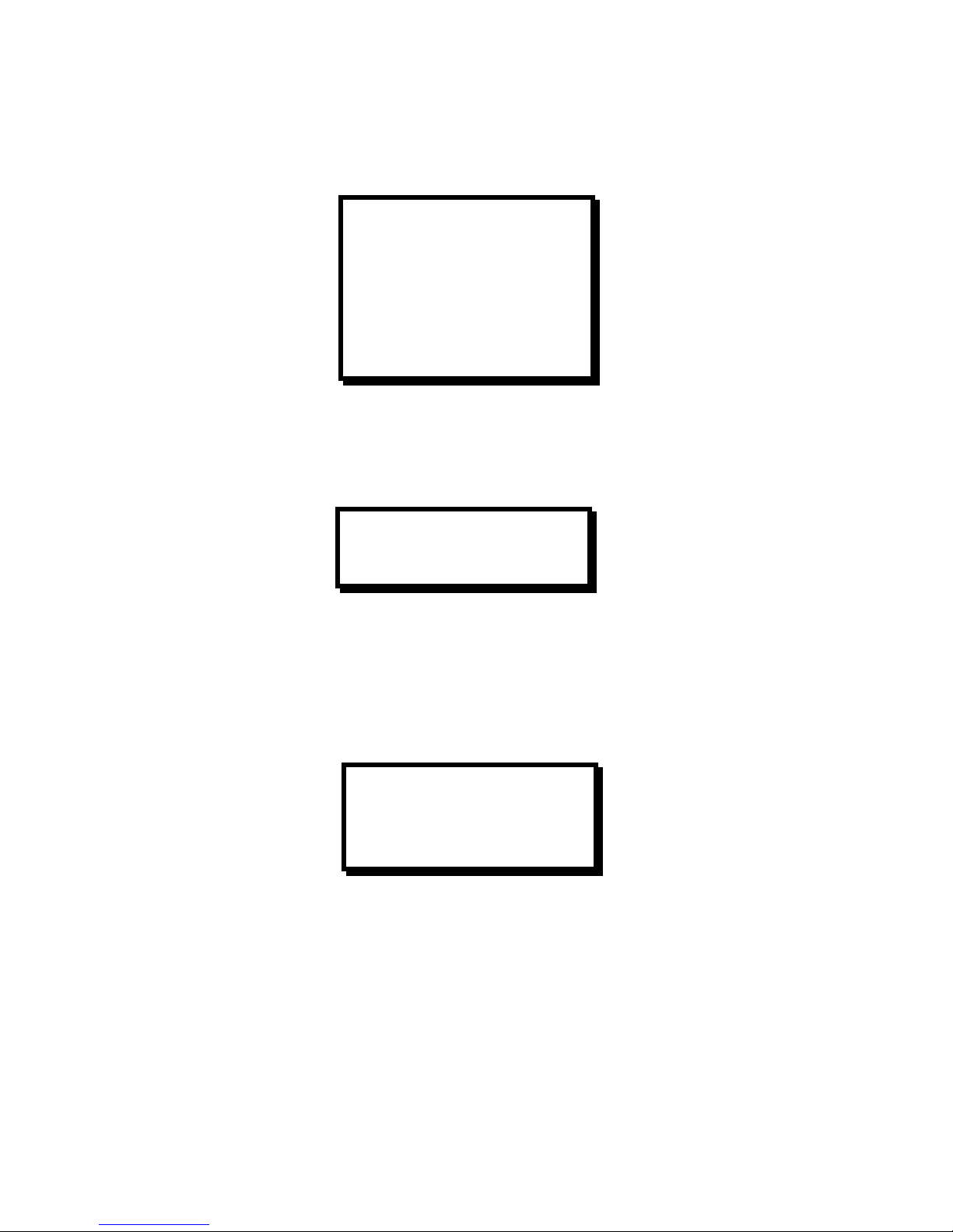
MIC, and Line controls control the individual inputs to the audio mixer. To change the volume, use the Adjust control
to scroll to the appropriate menu item and press Select. The volume is changed as the Adjust control is turned. The
following is the default startup state of this menu.
Audio Input Setup Menu
Input source parameters are adjusted within this menu, which also displays the currently selected audio source.
The source Level feature allows a user to select between Professional and Consumer input levels. The Trim feature
allows user to adjust the input audio gain from 0% to 100%. The default settings are illustrated.
VOLUME ADJUSTMENT
MAIN MASTER 45%
MAIN SOURCE 59%
MAIN MIC 0%
MAIN LINE 42%
PREVIEW MASTER 45%
PREVIEW SOURCE 59%
PREVIEW MIC 0%
PREVIEW LINE 42%
AUDIO INPUT SETUP 1
LEVEL CONSUMER
TRIM 50%
MIC and LINE Setup Menu
The MIC and LINE Setup Menu allows the user to define the MIC Gain (-43, -50, or –57dB), microphone Phantom
Power mode (Off or On), and the LINE input levels (Pro or Consumer). The default settings are illustrated.
Audio Effects Menu
Audio breakaway transition time, breakaway crossfade delay and global audio signal delay are set in this menu.
Transition time is only active in A/V breakaway mode and refers to the total time required to dissolve audio from one
source to another. Audio crossfade delay is the amount of time from the beginning of an audio transition to the
beginning of the introduction of the second source. Crossfade delay can never be greater than the transition time,
which varies from 0.0 to 5.0 seconds.
The global signal delay is used for additional audio delay required to synchronize audio with corresponding video if
video delays are introduced by external devices. The default settings are illustrated.
MIC AND LINE SETUP
MIC GAIN -43dB
PHANTOM POWER OFF
LINE LEVEL CONSUMER
24 Compass S
2
Page 33
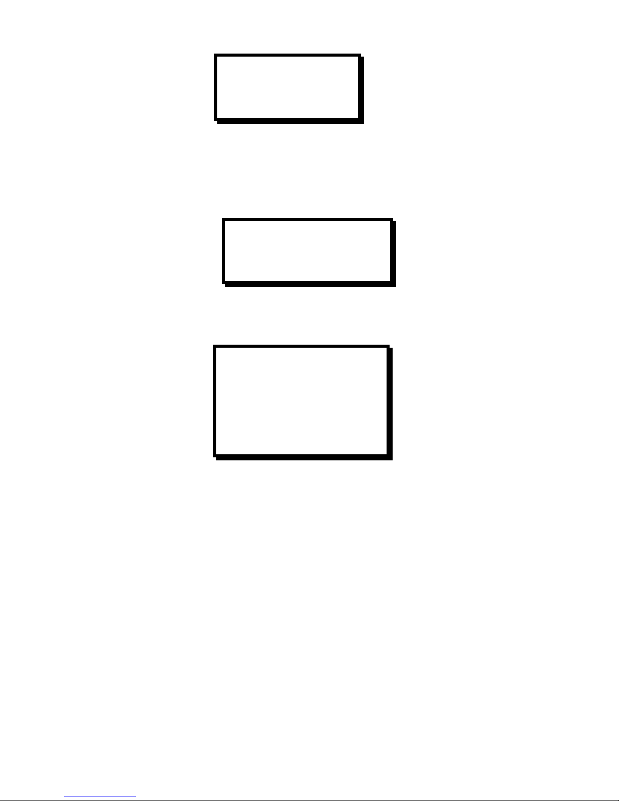
AUDIO EFFECTS
TRANSITION TIME 1.0
CROSSFADE DELAY 0.0
SIGNAL DELAY 0
Effect Menu
The Effect Menu allows the user to adjust the dissolve duration, as well as the type of transition and the threshold
percentage for keying. The dissolve time can be adjusted from 0.0 to 5.0 seconds. The user can select whether to
use Cut or Dissolve to transition keying. Also the user can adjust the Key Threshold from 0.0% to 100
EFFECT
DISSOLVE TIME 1.0
KEY TRANS NONE
KEY THRESHOLD 5%
Output Setup Menu
The Output Setup Menu allows the operator to select the desired video output format and the output of the internal
test pattern generator.
OUTPUT SETUP
FORMAT 1024x768
FRAME RATE XX.XXHZ
SYNC PREVIEW -H-V
SYNC MAIN1 -H-V
SYNC MAIN2 -H-V
TEST PAT OFF
RASTER BOX OFF
Output Format
The Output Format menu item allows the user to select an output format that matches the native resolution of the
projection device in order to optimize image quality. To perform adjustments, scroll to the Format menu line, select
the menu item with the Select key and then turn the Adjust control to select the desired output format. The available
output formats are; VGA (640x480), SVGA (800x600), XGA (1024x768), SXGA (1280x1024) as well as the following
plasma display formats: 1280 x 720, 1280x726, 1365x768, and 1365x1024. Press Select to accept the newly
entered settings or ESC to exit without accepting the changes that have been input. Please note that selections for
this menu item do not become active until the Select key is depressed. This differs from the operation of some other
menus where changes occur as soon as parameters are changed.
Frame Rate
The Frame Rate menu item allows the user to select the desired output frame rate. To perform adjustments scroll to
the Frame Rate menu line, select the menu item with the Select Key and then turn the Adjust control to select the
desired output frame rate (50Hz, 59.94Hz or 75Hz).
NOTE: To eliminate the potential for frame rate artifacts it is recommended that the output frame rate be set to match
the input frame rate for video sources (59.94 Hz for NTSC, 50 Hz or 75Hz for PAL).
Sync
The Sync menu items allow the user to independently select the desired output sync format for the Preview and for
the two Main outputs. To perform adjustments, scroll to the appropriate Sync menu line (Preview, Main1 or Main2),
select the menu item with the Select key and then turn the Adjust control to select the desired output sync format.
The available output formats are +H+V (active high Horizontal Sync, active high Vertical Sync), +H-V (active high
Compass S2 25
Page 34

Horizontal Sync, active low Vertical Sync), -H+V (active low Horizontal Sync, active high Vertical Sync), –H-V (active
low Horizontal Sync, active low Vertical Sync), and –C (active low Composite Sync). Press Select to accept the newly
entered settings or ESC to exit without accepting the changes that have been entered.
Test Pattern
The Test Pattern menu item allows the user to select a test pattern for display. To select a test pattern, scroll to the
Test Pattern menu line, select the menu item with the Select key and then turn the Adjust control to select the desired
test pattern. The available test patterns include Horizontal Ramp, Horizontal Bars, Burst (2 On-2 Off), Color Bars,
Black, White, and Cross Hatch. Press Select to output the selected test pattern. The Off selection is used to disable
the internal test pattern generator and return to live conversion mode.
Raster Box
The Raster Box menu item allows the user to overlay a border on the Main or Preview output images. To control the
display of the Raster Box, scroll to the Raster Box menu line, select the menu item with the Select key and then turn
the Adjust control to select the desired output (Preview, Main, Both, or Off). The Off selection is used to disable the
display of the Raster Box. The raster box can be displayed on the test patterns or over live data.
File Menu
The File Menu allows the user to assign one of 64 input configuration files to each of the eight input sources. The
input configuration file number and file name associated with each of the eight inputs are show in the menu as
illustrated below.
FILE MENU
IN 1 1 DVD1
IN 2 2 DVD2
IN 3 3 COMP1
IN 4 4 COMP2
IN 5 5 BETA1
IN 6 6 BETA2
IN 7 7 YUV1
IN 8 8 EMPTY
DELETE A FILE >>
IN1 – IN8
To assign an input configuration file to a source, simply scroll down to the desired input source and press Select to
select the menu item. Use the Adjust knob to select the desired input configuration file and then press Select again
to complete the file association.
Delete A File
To delete an input configuration file, scroll to the Delete A File menu item and press Select to enter the Delete A File
submenu.
Miscellaneous Menu
The Miscellaneous Menu has options for changing serial port configuration and backlight status, as well as
performing a factory reset, which clears all user files.
26 Compass S
2
Page 35
MISC MENU
SYSTEM SAVE
CONFIG SERIAL >>
TECH SUPPORT >>
BACKLIGHT >>
A/V MODE INTEGR
REMOTE PROTOCOL >>
FACTORY RESET >>
System Save
Allows the user to save the input file settings to non-volatile memory.
Config Serial
Allows the user to change ECHO from ON/OFF. BAUD RATE can be adjusted from 1200, 9600, 19.2K and 38.4K.
DATA BIT has the option of 7 or 8. STOP BIT can be changed between 0 and 1. PARITY supports NONE, EVEN or
ODD. RESET will default the settings to Baud = 38.4, Parity = None, Data Bits = 8 and Parity = None. These settings
are used for both RS232 and RS485 communications.
CONFIG SERIAL
ECHO ON
BAUD RATE 38.4K
DATA BIT 8
STOP BIT 1
PARITY NONE
RESET RS-232
Tech Support Menu
Displays the latest version of software and customer service numbers to contact if a problem is encountered.
TECH SUPPORT MENU
SOFT VER 1.06 0 A
PHONE 800.332.FSR1
Remote Protocol Menu
Provides the user with a means to set the serial communication protocol between RS232 and RS485. If RS485 is
selected, the unit's ID can be set to any number from 1 to 32. The front panel is locked when the RS485 protocol is
selected.
REMOTE PROTOCOL
SERIAL MODE RS232
Backlight Menu
Allows the user to choose whether the display buttons are lighted or not.
Compass S2 27
Page 36

A/V Mode
Allows the user to select between integration and presentation modes. In integration modes, after a transiton both
main and preview displays show the same image, and the source button flashes between red and green.
In presentation mode the main and preview displays switch images on a transition, and the red and green input
source buttons switch color. Example: Main is set on input 4 and preview is set on input 2, pressing the cut button in
presentation mode will cause the main to display input 2 and preview 4, the input source 2 button which was green
turns red, and the input source button 4 which was red turns green.
Remote Protocol
Allows the user to choose between RS232 and RS485 communications. If RS485 is chosen, the Compass S2
prompts for an ID >.
Factory Reset Submenu
DELETE ALL USER
FILES AND RESET?
<SEL> = YES
<ESC> = NO
Pressing the SEL key will perform a factory reset. Pressing ESC key will return the user to the previous menu.
KEYING and FREEZE Two New Features
Keying
Keying allows the user to overlay one scaler image over another; this feature is available only when the S2 is in the
“presentation” mode and and “video breakaway” is set:
To enter presentation mode press the MISC button, scroll down to A/V MODE press select to select the A/V MODE,
then use the knob to display PRESEN, then press the SELECT button to set A/V MODE to “presentation”.
To set the unit in “video breakaway” mode push the AV MODE pushbutton on the front panel until it turns green and
the word “Breakaway” is displayed in the FLD window.
Setup
Press the EFF button, scroll to KEY TRANS and select either CUT or DISSOLVE then press SELECT. Scroll down to
KEY THRESHOLD, press SELECT. Use the knob to change the threshold to more than 0%(20% is usually a good
starting point), and press SELECT. Press MISC to exit setup.
Activate
The user will preview the input source to overlay using the input source buttons. To engage keying, press and hold
the ESC and MIC buttons at the same time, The MIC button will blink while keying is active. Pressing the transition
button chosen as the KEY TRANS will overlay the main screen with the preview screen.
Deactivate
Press the key chosen as the KEY TRANS to transition keying off the main. To disengage keying, press and hold the
ESC and MIC
buttons at the same time, the MIC button will stop blinking.
28 Compass S
2
Page 37

Freeze
The freeze feature allows the user to freeze the image on main and preview. It is recommended that the S2 be in
presentation mode while using the freeze feature.
To enter the presentation mode press the MISC button, scroll down to A/V MODE press select to select A/V MODE,
then use the knob to display PRESEN, then press the SELECT button to set A/V MODE to presentation.
To freeze an Image
Press and hold the ESC button, then press the red input source button to freeze the main, or the green input source
button to freeze the preview. The frozen input source button will flash and the text "FRZ" will be displayed in place of
the file name on the display.
If main is frozen and the user presses the cut or dissolve button, the frozen image will be transitioned to the preview,
and visa versa.
To Unfreeze an Image
Press and hold the ESC button, then press the red input source button to freeze the main, or the green input source
button to freeze the preview. The button will stop blinking and the display will return to the file name.
Compass S2 29
Page 38

Page 39
CHAPTER FOUR
Serial & Remote Command Syntax
What you will find in this chapter…
Serial Port Default Configuration
Serial Commands
Remote Commands
Compass S2 Command List/Description
Terminal Remote Control
4
Compass S2 31
Page 40

Serial & Remote Command Syntax
Serial Parameters
The following are the default parameter settings for serial communication:
Baud Rate is 38.4.
Parity is NONE.
Stop Bit is 1.
Data Bit is 8.
Echo is ON or OFF. (Applies to RS232 mode only)
Default settings can be changed with the MISC menu as described on page 26. For RS-232 signal connections, refer
to page 10.
Serial Command Formats
RS232 Mode
The Graphics Board will respond with a '#' prompt when the command processor is ready for a command.
The command syntax is shown below
cmd arg1 arg2 … argn<CR>
cmd cmd is any valid Graphics Board command, typically 2 to 6 alphabetic (non numeric) characters.
arg arg1, arg2, … argn are required or optional parameters depending on the command used.
<CR> carriage return (ASCII 13) terminates the command
A space (ASCII 32) must be inserted between the command and any arguments that follow. A space must also be
inserted between all argument parameters except for the last argument in the chain.
All commands in RS232 mode must be terminated with a carriage return (ASCII 13). The carriage return will tell the
command processor to begin execution of the command.
If the command is not recognized as a valid command, a '? 4' is returned for unknown command where ‘4’ is a
numeric error code for Command Not Available. If the command is recognized but the syntax is incomplete or
required parameters are missing then '? 1' will be returned, where ‘1’ is a numeric error code for Command Format
Error. See below for a complete description of Error Codes.
Query commands will return the following:
=result number
#
The '=' indicates a result from a command is following. The 'result' will follow directly after the '='. The value of the
result will vary depending on the query command used. A new line will be generated and the prompt will indicate the
system is ready for a new command.
Error Codes
Command Format Error 1
Command Range Error 2
Command Execution Error 3
Command Not Available 4
RS485 Mode
Single commands will be combined with a prefix, device number, command separator and suffix to form a command
string as shown below:
Single Command Format:
<prefix><id><cmd arg1 arg2 ..argn><suffix>
32 Compass S
2
Page 41
Multiple Command Format:
<prefix><id><cmd arg1 arg2 ..argn>,<id><cmd arg1 arg2 ..argn>,…,<id><cmd arg1 arg2 ..argn><suffix>
prefix a single * character (ASCII 42).
id id is the device number in the range of 1 to 32. This can be a single character for values less
than 10, no preceding zero is required.
cmd cmd is any valid Graphics Board command, typically 2 to 6 characters in length
arg arg1,2,n is any required or optional parameters needed for the command, separated by
spaces (ASCII 32)
, separates multiple commands
suffix a single '!' character (ASCII 33).
Example:
*12XYZ A 9,9PDQY 1234,31WX 200 98!
The command string is started by the prefix character '*'. The first command follows directly after the prefix. The
example shows that device 12 should process the XYZ command with A and 9 as parameters. A coma (ASCII 44)
separates the commands. Device 9 will process the PDQY command with a parameter of 1234 and device 31 will
process the WX command with parameters of 200 and 98. The suffix character '!' follows directly after the last
command to end the command string.
Commands received in the command string will not be processed until the suffix character '!' is received. This format
allows commands to be stack to the same or multiple devices and executed when the suffix '!' character is received
by all units. Any incomplete or unknown commands will be ignored. The maximum number of commands that can
be stacked per unit is 16. Each unit will only stack those commands assigned to it, even though all units receive the
same command string.
During queue processing, no input buffer processing is performed. Characters sent through the serial port during
queue processing are stored in the input buffer. If hardware flow control is not active, it is important to guarantee that
the input buffer limit is not exceeded before completion of the last command string. Note: The command queue does
not support backspace characters.
To minimize bus traffic the command words will be kept as short as possible. The units will not respond with prompts
or any command error conditions. Echo will be disabled when RS-485 mode is selected.
Configuration Load and Save
These commands can be used to store or duplicate various Compass S2 configuration files (CFG's). The files can be
loaded off the Compass S2 to a disk file on a PC.
Compass S2 33
Page 42

Download CFG
DL op nn sclr<CR>
Parameters:
Op - [I|P] Download Input library or Program Sequence Steps.
nn Selects the index number of the configuration. When Op = I, this number
can be zero for the current configuration or a number between 1 - 64 for a
User Library Configuration. When Op = P, this number should always be 1.
sclr – [A|B|M|P] Used only when nn = 0, otherwise parameter not required.
Example: DL I 12<CR>
Downloads the input cfg number 12
This command will download a configuration file from the Compass S2 to the serial port. The download begins
immediately after the command is initiated. The user should verify that the CFG is valid before downloading. The
format of the CFG data is
<SOH><LIB><Index><Size><BINARY DATA><Sx>
Where
<SOH> is StartOfHeader (0x01)
<LIB> is the current library type, [I]nput or [P]rogram Sequence
<Index> is the library index of this file, as a byte value.
<Size> is the number of bytes in the binary data field, as a byte value.
<BINARY DATA> is the data library structure in binary format.
<Sx> is a 8 bit checksum in as a byte field, applied to binary data only.
Current file sizes are: Input Library - 211 bytes (1688 bits)
All files will have additional 4 bytes (32 bits) of header information added to them and 1 byte (8 bits) of checksum
information at the end of the file.
Upload CFG
UL op nn s[8]<CR>
Parameters:
Op - [I|P] Upload Input library or Program Sequence Steps.
nn Selects the index number of the configuration. When Op = I,
the number can be between 1 – 64 for a User Library
Configuration. Use 0 to load the file into the index it originated
from. When Op = P, the number needs to be 1.
S[8] Optional parameter to override the 8 character description of
the file.
Example: UL O 3<CR>
Uploads file to the output cfg location 3.
This command will upload a configuration file from the serial port to the Compass S2. The upload begins once a valid
SOH character is detected indicating the start of header. This allows multiple units to receive the UL command and
then wait to receive the same CFG file from a PC or source Compass S2.
34 Compass S
2
Page 43

Remote Command Format
All commands with sclr allow either Scaler [A] or Scaler [B] to be selected. If this parameter is not used, Scaler A is
used as the default. Inquiry commands will accept the scaler as an optional parameter. The default is to return
information for Scaler A. Additionally, the sclr parameter will accept [M]ain or [P]review as valid operands.
ACFG sclr Auto Input Configuration (1:1 Sampling): sclr[A|B|P|M]
ADBG d Audio debug: d[0|1]
ADLY d Audio delay adjustment: t[0..50]
AMTE M L P m l p Audio mute control: MLPmlp[0|1] (mute=0),
AOIWN n n n n sclr Area of Interest Window:
Right Edge, HWidth, Bottom Edge, VHeight,
AOUT P p h Audio output control: Pph[0|1]
ARST u Audio reset control: u[0|1]
ARTE a b Audio route: ab[0..7]
ARTEM c Audio route main: c[0..8] where 8 is silent
ARTEP c Audio route preview: c[0..8] where 8 is silent
ASEN p m l s Audio sensitivity: pl[0|1] m[1..3] s[0..15]
ASTAT Audio status: return current status as a sequence of bytes
ASTAV Audio volume status: return current volume status as a
sequence of bytes
ATRM c v Audio source trim: c[1..8] v[0..51]
ATRN t c Audio transition: t[0..5000] c[0..5000]
AVOL t i r Audio volume: t[1..8] i[-1,1] r[10,25,40]
AVS t m Set audio video mode t[0,1] 0:integration 1:presentation
m[1…3] 1: Video 2: Audio 3: Both
CHKSUM Returns the list of flash-stored file checksums
CMDST? Last Command Status Inquiry,
COMCK op Communication Check:
op[D|U] DOWNLOAD|UPLOAD 128 bytes
DEBUG? Debug Inquiry
DL op nn sclr Download CFG: op[I|P] nn[0-64] sclr[A|B|P|M]
ECHO port n Echo Enable/Disable:
port[A|B] COM_A|COM_B n[0|1] DIS|ENA
FREEZ n sclr Freeze: n[0|1] OFF|ON sclr[A|B|P|M]
FSB n sclr Force Scaler Black: n[0|1] OFF|ON sclr[A|B|P|M]
HELP I Help Command: i[A-Z], Help Index
IBRT op nnn sclr Input Brightness:
op[C|R|G|B] (C)n[75 - 125]% (RGB)n[-25 - 25]%
ICDEL nn Input Configuration Delete: n[1-64]
ICFGN nn Input Configuration File Name: n[1-64]
ICGTE n sclr Input Clamp Gate: n[0-2], SYNC|PRCH|PDLY sclr[A|B|P|M]
ICNT op nnn sclr Input Contrast: op[C|R|G|B] (C)n[75 - 125]% (RGB)
n[-25 - 25]%
ICPH op sclr nn Input Clock Phase: op[A|D|M|I], sclr[A|B|P|M], n[0-31]
ICPHO op sclr nn Input Clock Phase Offset:
op[A|D|M|I], sclr[A|B|P|M], n[-16 to 16]
ICPL op sclr nnnn Input Clocks Per Line: op[A|D|M|I], sclr[A|B|P|M], n[0-4096]
ICREC nn sclr Input Configuration Recall: n[1-64] sclr[A|B|P|M]
ICRST sclr Input Configuration Reset: sclr[A|B|P|M]
ICSAV nn s[8] sclr Input Configuration Save: n[1-64] s[Name] sclr[A|B|P|M]
ICSP n sclr Input Colorspace: n[0-6], RGB|B50|B60|MII|EBU|NTSC|SVID
IHRE sclr? Input Right Edge Inquiry: sclr[A|B|P|M]
IHUE nnn sclr Input Hue: n[0-360 degrees] sclr[A|B|P|M]
IHW sclr? Input Left Width Inquiry: sclr[A|B|P|M]
IRSP op nnn sclr Input Raster Size/Position:
op[L|R|T|B] nnn[-999 - 999] sclr[A|B|P|M]
ISAT nnn sclr Input Saturation: n[50-200]% sclr[A|B|P|M]
ISYNC n sclr Input Sync: n[0-3], SOG|CSYN|H&V|AUTO sclr[A|B|P|M]
KEY c sclr n Luma Keying n[ ‘X’ | ’K’ | ’W’ ] OFF|KEY|WINDOWING
Compass S2 35
Page 44

LCK sclr Video Lock: sclr[A|B|P|M]
LCK sclr? Video Locked Inquiry: sclr[A|B|P|M]
LOADR Loader Mode: Place Graphics Board into Loader Mode
MADB n sclr Motion Adaptive De-interlacing Bypass:
n[0|1] DISABLE|ENABLE sclr[A|B|P|M]
MSTAT sclr FACTORY USE ONLY
OCRECF n Output Configuration Recall: n[0-7]
OFRATE n Output Frame Rate: n[0|1|2] 59.94Hz|50Hz|75Hz
OSYNC n op Output Sync:
n[1-5], -C|+H+V|+H-V|-H+V|-H-V op[B|H|P] BNC|HD15|Preview
OTPM m ty iv bx gr Output Test Pattern: m[0-3], ty[0-4], iv, bx, gr [0|1]
OFF|ON
PFSD n sclr Progressive Frame Seq Det. (3-2 Pulldown):
n[0|1] DIS|ENA sclr[A|B|P|M]
PHCAL FACTORY USE ONLY
PHRST FACTORY USE ONLY
PHSCAL Phase Calibration
PHSET FACTORY USE ONLY
RESET op Reset System: op[A|F] All|Factory Defaults
RTE n c Router Switch Command:
n[1-9] Input Source Sel - 9=BLK c[M|P] Main|Preview
SSTAT FACTORY USE ONLY
STAT? FACTORY USE ONLY
STATS? Print Log File
T nnn T-BAR Transition:
nnn[0 - 255] where 0 = Scaler B, 255 = Scaler A
TBLS n Terminal Backlight Status: n[0|1] OFF|ON
TCM n Terminal Remote Control Mode: n[0|1] FOLSOM/VISTA|FSR
TDI n Front Panel Display Intensity: n[25|50|75|100]
TDL FACTORY USE ONLY
TER nnn Terminal Encoder Rate: n[-100 - 100]
TKC nn Terminal Key Code: n[06 - 7F]
TLSR Terminal LED Status
TRCF n nn Terminal Recall Configuration File:
Input Source n[1-8] File Num nn[1-64]
TRN dst dn n.n n Transition Inputs: dst[A|B|P|M] dn[1-8], n.n[0-5.0]sec
n[0-6]
UL op nn s[8] Upload CFG: op[I|P] Input Cfg|Program Steps nn[0-64] s[8]
VBW n sclr Video Bandwidth: n[0|1] FULL|REDUCED sclr[A|B|P|M]
VER Version Information
VPK n sclr Video Peaking: n[0|1|2|3] MIN|NOM|INC|MAX sclr[A|B|P|M]
VRBOS n Verbose Mode: n[0|1], OFF|ON
Compass S2 Command List/Description
Command: ACFG
Description:
Automatically configure one-to-one sampling input configuration.
Parameters:
sclr – scaler value (A,B,P or M)
Example:
acfg A – automatically configure scaler ‘A’.
Command: ADBG
Description:
Toggles led1 on the audio interface board
36 Compass S
2
Page 45

Parameters:
d - led state, 0=off, 1=on
Example:
adbg 1 - turn led1 on
Command: ADLY
Description:
Audio signal delay adjustment for external video device synchronization
Parameters:
t - signal delay time in milliseconds [0..50]
Example:
adly 25 - add 25 ms of audio delay to all channels
Command: AMTE
Description:
Audio mute control
Parameters:
M - Main microphone mute state (0=mute, 1=active)
L - Main line mute state
P - Main source state
m - preview microphone mute state
l - preview line mute state
p - preview source state
Example:
amte 0 0 0 1 1 1 - mute all main audio outputs
Command: AOUT
Description:
Audio output relay control to enable or disable main, preview and headphone relays.
Parameters:
P - main relay control (0=off, 1=on)
p - preview relay control
h - headphone relay control
Example:
aout 1 1 1 - enable all outputs
Command: ARST
Description:
Audio board reset control
Parameters:
u - reset the audio board uart if 1
Example:
arst 1 - resets the uart
Compass S2 37
Page 46

Command: ARTE
Description:
Route audio router inputs to output channels a and b.
Parameters:
a - channel a input [0..8], where 8 is the silent channel
b - channel b input [0..8], where 8 is the silent channel
Example:
arte 0 8 - route input channel 1 to output a and the silent channel to output b
Command: ARTEM
Description:
Route audio main channel
Parameters:
c - input [0..8], where 8 is the silent channel
Example:
artem 0 - route input channel 1 to main
Command: ARTEP
Description:
Route audio preview channel
Parameters:
c - input [0..8], where 8 is the silent channel
Example:
artep 8 - route silent channel to preview
Command: ASEN
Description:
Audio sensitivity settings for audio source inputs, line input, microphone gain and microphone
phantom power.
Parameters:
p - phantom power setting (0=off, 1=on)
m - microphone gain settings 1=-43dB, 2=-50dB, 3= -53dB
l - line level setting (0=consumer, 1=professional)
s - source level setting bits (0=consumer, 1=professional)
Example:
asen 0 1 0 0x01 - set the phantom power off, gain to -43dB, line level to consumer and source 1 to
professional (notice that the source level setting is an eight bit value)
Command: ASTAT
Description:
Factory use only, returns a number of status bytes indicative of the current audio state.
Parameters:
None
Example:
astat
38 Compass S
2
Page 47

Command: ASTAV
Description:
Factory use only, returns a number of status bytes indicative of the current audio volume states.
Parameters:
None
Example:
astav
Command: ATRM
Description:
Audio source trim command
Parameters:
c - audio source channel [1..8]
v - audio trim setting [0..51]
Example:
atrm 2 26 - set audio input channel two trim value to 26
Command: ATRN
Description:
Audio transition command.
Parameters:
t - transition time in milliseconds [0..5000]
c - crossfade delay time in milliseconds [0..5000]. It is always less than t.
Example:
atrn 3000 1000 - perform an audio transition of 3 seconds with a crossfade delay of one second.
Command: AVOL
Description:
Audio volume adjustment.
Parameters:
t - volume type
1 = main master volume
2 = main source volume
3 = main microphone volume
4 = main line volume
5 = preview master volume
6 = preview source volume
7 = preview microphone volume
8 = preview line volume
i - volume decrement or increment (-1=decerment,1=increment]
r - volume rate of change
10 - fast
25 - moderate
40 - slow
Example:
avol 1 -1 10 - reduce the main master volume as quickly as possible
Compass S2 39
Page 48

Command: AOIWN
Description:
Allows sizing adjustments of the input source with respect to the output raster.
Parameters:
n – Right Edge
n – Horizontal Width (Pixels)
n – Bottom Edge
n – Vertical Height (Lines)
sclr – Scaler [A|B|M|P]; Scaler A | Scaler B | Main | Preview
Example:
AOIWN A? : Returns for Scaler A: =n n n n n, (=Right Edge, Horizontal Width, Bottom Edge, Vertical Height, Clock
Samples per Line).
Command: AVS t m
Description: Sets integration or presentation mode
Set audio video mode t[0,1] 0:integration 1:presentation
m[1…3] 1: Video 2: Audio 3: Both
Command: CHKSUM
Description:
Returns the list of flash-stored file checksums
Parameters:
None
Example:
CHKSUM: Returns the following.
Flash-stored file checksums.
ab25 - spinc.rbf
4a6f - spoc.rbf
d4ec - spmx.rbf
2b69 - terminal.bin
57c6 - pm_menu.cs
d3ff - Compass S2.dwn
Command: CMDST?
Description:
Returns status of the last command that executed
Parameters:
None
Example:
CMDST? : 0 = Completed; 1 = Format Error; 2 = Range Error;
3 = Execution Error; 4 = Command Not Available Error.
Command: COMCK op
Description:
Allows a remote control system to verify communications between itself and the Compass S2.
Parameters:
op – [D]ownload or [U]pload data
n – Amount of data to upload or download. This is an optional parameter that defaults to 128 bytes.
Example:
COMCK U : After the terminating <CR>, the systems waits for 128 bytes to be sent.
40 Compass S
2
Page 49

COMCK D : The system transmits 128 bytes to the remote controller.
Command: DEBUG?
Description:
Returns the status of Debug Mode.
Parameters:
None
Example:
DEBUG? : 0 = Debug Mode Disabled; 1 = Debug Mode Enabled
Command: DL op n sdr
Description:
Download input file configurations or a Program Sequence from the Compass S2.
Parameters:
op - Input configuration or Program Sequence; [I|P]
nn - Index Number; [0-64]
sclr - Scaler [A|B|M|P]; Scaler A | Scaler B | Main | Preview
Example:
DL I 2 : Download input configuration at index 2.
DL I 0 A : Download the current information loaded on Scaler A.
DL P 1 : Download the stored program sequence steps.
Command: ECHO prt n
Description:
Enable or Disable ECHO.
Parameters:
port - Com Port; [A|B] Note: Com A = 25-pin Remote Port
n - Disable or Enable; [0|1]
Example:
ECHO A 0 : Disable ECHO on Com A.
Command: FREEZ n sclr
Description:
Enable/Disable Freeze.
Parameters:
n - Freeze Enable/Disable; n[0|1], OFF|ON
sclr - Scaler [A|B|M|P]; Scaler A | Scaler B | Main | Preview
Example:
FREEZ 1 A: Enables freeze on the dis play on Scaler A
FREEZ 0: Disables freeze on the display on Scaler A.
Command: FSB n sclr
Description:
Force Scaler Black.
Parameters:
n - Force Scaler Black Disable/Enable; n[0|1], OFF|ON
sclr - Scaler [A|B|M|P]; Scaler A | Scaler B | Main | Preview
Example:
FSB 1 A: Scaler A will show a black screen
FSB 0 A: Scaler A will show the current input source.
Compass S2 41
Page 50

Command: HELP I
Description:
Displays the list of available command on a terminal emulator.
Parameters:
i – Alphabetical Inde x [A – Z]; Optional Parameter
Example:
HELP?: Returns the command list.
HELP P?: Returns the entire command list starting with the first command that starts with “P”.
Command: IBRT op nnn sclr
Description:
Adjusts the Input Brightness value.
Parameters:
op - Select Brightness Control;
[C|R|G|B] Common, Red Offset, Green Offset, Blue Offset
nnn - Brightness value; C Range 75 - 125%, RGB Range -25 - 25%
sclr - Scaler [A|B|M|P]; Scaler A | Scaler B | Main | Preview
Example:
IBRT C 110.5 A: Adjusts the Input Brightness on Scaler A to be 110.5%.
IBRT R 10 M: Adjusts the Red Offset to 10% for the Input on Main.
Command: ICDEL nn
Description:
Deletes a specified Input Configuration.
Parameters:
nn - Input Configuration Index; n[1 - 64]
Example:
ICDEL 2: Deletes input configuration two.
Command: ICFGN n
Description:
Fetch input configuration file name.
Parameters:
n - File number [1 – 64]
Example:
ICFGN 1: Returns the name associated with file number 1.
Command: ICGTE n sclr
Description:
Adjusts the Input Clamp Gate mode.
Parameters:
n - Clamp Gate Selection; SYNC|PRCH; 0|1|2
sclr - Scaler [A|B|M|P]; Scaler A | Scaler B | Main | Preview
Examples:
ICGTE 0 A: Adjusts the Input Clamp Gate on Scaler A to be SYNC
ICGTE 1 A: Adjusts the Input Clamp Gate on Scaler A to be PRCH
ICGTE 2 A: Adjusts the Input Clamp Gate on Scaler A to be PDLY
Command: ICNT op nnn sclr
Description:
42 Compass S
2
Page 51

Adjusts the Input Contrast values.
Parameters:
op - Select Contrast Control;
[C|R|G|B] Common, Red Offset, Green Offset, Blue Offset
nnn - Contrast value, C Range 75 - 125%, RGB Range -25 - 25%
sclr - Scaler [A|B|M|P]; Scaler A | Scaler B | Main | Preview
Example:
ICNT C 100.8 A: Adjusts the Common Input Contrast valu e as 100.8%.
ICNT G 15: Adjusts the Green Contrast Offset to 15% on Scaler A.
Command: ICPH op sclr nn
Description:
Adjust the Input Clock Phase.
Parameters:
op - [A|D|M|I] Automatic | Debug | Manual | Increment
Note: Debug Mode is for Factory Use Only
sclr - Scaler [A|B|M|P]; Scaler A | Scaler B | Main | Preview
nn – Phase Number [0 – 31] when op = M
Number to Increment by when op = I
nn – File Number [0 – 64]
Example:
ICPH A P: Automatically adjust the Input Clo ck Phase on Preview.
ICPH M M 12 0: Set Input Clock Phase on Main to 12 for the currently dis played input.
ICPH M M 12 2: Set Input Clock Phase for File Number 2 to 12.
ICPH I A 3: Increment the Input Clock Phase on Scaler A by 3.
Command: ICPHO op sclr nn
Description:
Adjust the Input Clock Phase Offset.
Parameters:
op - [A|D|M|I] Automatic | Debug | Manual | Increment
Note: Debug Mode is for Factory Use Only
sclr - Scaler [A|B|M|P]; Scaler A | Scaler B | Main | Preview
nn – Phase Offset Number [-16 – 16] when op = M
Number to Increment by when op = I
nn – File Number [0 – 64]
Example:
ICPHO A P: Automatically adjust the Input Clock Phase Offset on
Preview.
ICPHO M M 12 0: Set Input Clock Phase Offset on Main to 12 for the currently displayed input.
ICPHO M A 12 2: Set Input Clock Phase Offset for File Number 2 to 12. If the scaler A source
displayed is derived from File Number 2, it will be updated as well.
ICPHO I A 3: Increment the Input Clock Phase Offset on Scaler A by 3.
Command: ICPL op sclr nnnn
Description:
Adjust the number of Input Clocks per Line.
Parameters:
op - [A|D|M|I] Automatic | Debug | Manual | Increment
Note: Debug Mode is for Factory Use Only
sclr - Scaler [A|B|M|P]; Scaler A | Scaler B | Main | Preview
nnnn – Number of Clocks per Line [0 – 4096] when op = M
Compass S2 43
Page 52

Number to Increment by when op = I
Example:
ICPL A P: Automatically adjust the number of Input Clocks per
line on Preview.
ICPL M M 1364: Set Input Clocks per Line on Main to 1364.
ICPL I A 4: Increment the number of Input Clocks per Line on
Scaler A by 4.
Command: ICREC nn sclr
Description:
Recalls a stored Input Configuration.
Parameters:
nn - Input Configuration Index; n[1 - 64]
sclr - Scaler [A|B|M|P]; Scaler A | Scaler B | Main | Preview
n - Router input to which the input signal is connected.
Note: Router Input parameter only used on Compass S2 Plus.
Example:
(Assuming there is a saved Input Configuration in Index #1)
ICREC 1 M: Loads the Input Configuration stored in Index #1 to the
source on Main.
ICREC 1 A 2: Loads the Input Configuration stored in Index #1 on Scaler
A. In this example the input signal is sourced on router
input 2.
Command: ICRST sclr
Description:
Resets the current input configuration of the scaler specified.
Parameters:
sclr - Scaler [A|B|M|P]; Scaler A | Scaler B | Main | Preview
Example:
ICRST A: Reset the input configuration for Scaler A.
Command: ICSAV nn s[8] sclr
Description:
Saves an Input Configuration to a specified index.
Parameters:
nn - Input Configuration Index; n[1 - 64]
s[8] - Input Configuration Name; s[Name] (Up to 8 characters, no spaces)
sclr - Scaler [A|B|M|P]; Scaler A | Scaler B | Main | Preview
Example:
ICSAV 1 TEST A: Saves the input configuration currently on Scaler A to Index #1 with the label
name TEST.
Command: ICSP n sclr
Description:
Adjusts the Input Color Space mode.
Parameters:
n - Color Space Selection; [0 – 6] RGB|B50|B60|MII|EBU|NTSC|SVID
If n = 254 or 255, then selection will increment or decrement through the list.
sclr - Scaler [A|B|M|P]; Scaler A | Scaler B | Main | Preview
Example:
ICSP 0 A: Adjusts the Input Color Space on Scaler A to be RGB.
44 Compass S
2
Page 53

Command: IHRE sclr?
Description:
Input Right Edge Inquiry.
Parameters:
sclr - Scaler [A|B|M|P]; Scaler A | Scaler B | Main | Preview
Example:
IHRE A?: Returns the pixel location of the Right Edge.
Command: IHUE nnn sclr
Description:
Adjusts the Input Hue setting.
(Only applicable if input is a NON-RGB source.)
Parameters:
nnn - Input Hue Selection; n[0 - 360]degrees
sclr - Scaler [A|B|M|P]; Scaler A | Scaler B | Main | Preview
Example:
IHUE 20 A: Adjusts the Input Hue selection on Scaler A to be 20 degrees.
Command: IHW sclr?
Description:
Input Horizontal Width Inquiry.
Parameters:
sclr - Scaler [A|B|M|P]; Scaler A | Scaler B | Main | Preview
Example:
IHW A?: Returns the total pixel width of the input on Scaler A.
Command: IRSP op nnn sclr
Description:
Adjusts the Input Raster Size/Position.
Parameters:
op - Select Raster Control; [L|R|T|B] Left, Right, Top, Bottom
nnn - Increment/Decrement value; [-999 – 999]
sclr - Scaler [A|B|M|P]; Scaler A | Scaler B | Main | Preview
Example:
IRSP R 10 A: Increments the Right Input Raster Size/Position by 10 on Scaler A.
Command: ISAT nnn sclr
Description:
Adjusts the Input Color Balance Saturation.
(Only applicable if input is a NON-RGB source.)
Parameters:
nnn - Input Saturation: n[50-200]%
sclr - Scaler [A|B|M|P]; Scaler A | Scaler B | Main | Preview
Example:
ISAT 110.0 A: Adjusts the Input Color Balance to 110.0 %.
Command: ISYNC n sclr
Description:
Adjusts the Input Sync selection.
Parameters:
Compass S2 45
Page 54

n - n[0 – 3], SOG|CSYN|H/V|AUTO
sclr - Scaler [A|B|M|P]; Scaler A | Scaler B | Main | Preview
Example:
ISYNC 0 A: Sets Scaler A to expect SOG on the input channel.
COMMAND: KEY N SCLR THRSHLD
Description:
Enables/Disables keying
Parameters:
n - [X|K|W], Off|On|Windowing
sclr - Scaler [M|P] Main|Preview
thrshld - Threshold 00 to 105
Example:
KEY K P 5 : Turns on keying on preview with 5% threshold.
Inquiry: KEY?
Returns: =n
Command: LCK sclr?
Description:
Video Lock Inquiry Command.
Parameters:
sclr - Scaler [A|B|M|P]; Scaler A | Scaler B | Main | Preview
Returns: =0 for NOT LOCKED
=1 for LOCKED/MATCHED
=2 for LOCKED/MISMATCHED.
Command: LOADR
Description:
Places unit into loader mode. This mode is used to perform field upgrades.
Parameters:
None.
Command: MADB n sclr
Description:
Bypass the Motion Adaptive De-Interlacing feature. This will reduce delay thru the system. This
feature is particularly effective when using live camera sources.
Parameters:
n - n[0|1], Disable or Enable
sclr - Scaler [A|B|M|P]; Scaler A | Scaler B | Main | Preview
Example:
MADB 0 A: Disable the Motion Adaptive De-I nterlacing.
Command: MSTAT sclr
Description:
FACTORY USE ONLY.
Parameters:
None.
46 Compass S
2
Page 55

Command: OCRECF n
Description:
Select the Output Resolution to use.
Parameters:
n - Output Resolution: n[0 – 7];
VGA|SVGA|XGA|720p|SXGA|1280x768|1365x768|1365x1024
Example:
OCRECF 2: Select output format to be XGA.
OCRECF T?: Translates the query output to return [0 – 7].
Command: OFRATE n
Description:
Select the Output Frame Rate to use.
Parameters:
n - Output Frame Rate: n[0 – 2], 59.94Hz | 50Hz | 75Hz
Example:
OFRATE 0: Select output frame rate to be 59.94Hz.
Command: OSYNC n op
Description:
Adjusts the Output Sync type for any of the three outputs.
Parameters:
n - Output Sync: n[1-5], -C|+H+V|+H-V|-H+V|-H-V
op - Output connector to make the change on: [B|H|P], where
B = BNC Output connector
H = Main HD15 Output connector
P = Preview HD15 Output connector
Example:
OSYNC 3 H: Adjusts the Output Sync value to be +H-V on the Main
HD15 connector.
Command: OTPM m typ inv bx gr
Description:
Enables/Disables the Output Test Pattern and selects Test Pattern options.
Parameters:
m - Output TP Enable: m[0-3],
OFF|ON (Main Only)|ON (Preview Only)|ON (Both Scalers)
typ - Test Pattern Type: typ[0-5] H Gray Ramp|H Gray Scale|Burst|Color Bars|Black|Live Mode
inv - Test Pattern Inversion: inv[0|1] OFF|ON
bx - Test Pattern Raster Box: bx[0-3] OFF|ON
gr - Test Pattern Grid: gr[0|1] OFF|ON
Example:
OTPM 2 3 0 1 0: Enables the Test Pattern to be shown on Preview.
Color Bars have been selected with inversion off, raster box on
and grid off.
Command: PFSD n sclr
Description:
Progressive Frame Sequence Detection. This command will allow the detection of 3-2 pulldown to
be enabled or disabled.
Parameters:
n - n[0|1], Disable or Enable
sclr - Scaler [A|B|M|P]; Scaler A | Scaler B | Main | Preview
Compass S2 47
Page 56

Example:
PFSD 0 A: Disable detection of 3-2 pulldown.
Command: PHSCAL
Description:
This command performs a Phase calibration. Refer to the appropriate section in the manual for the
procedure on how to setup the Compass S2 before using this command.
Parameters:
None.
Example:
PHSCAL: The system will perform a Phase c alibration.
Command: RESET op
Description:
Resets the system to factory defaults.
Parameters:
op - Reset operation: op[A|F] All|Factory
Example:
RESET A: Resets system to factory defaults and deletes all user input
configuration files.
RESET F: Resets system to factory defaults but leaves any user input
configuration files intact.
Command: RTE n op
Description:
Switches the router preview input.
Parameters:
n - Select source to route: n[1-9] where 9 = BLK
op - Output to which the source is routed: op[M|P] Main | Preview
Example:
RTE 4 P: Switches the Preview to router input 4.
Command: SSTAT?
Description:
FACTORY USE ONLY
Example:
SSTAT A? : Returns a system status value.
Command: STAT?
Description:
FACTORY USE ONLY
Parameters:
None
Example:
STAT? : Returns a system status value.
Command: STATS?
Description:
Prints a System Status Log.
Parameters:
48 Compass S
2
Page 57

None
Example:
STATS? : Status log will be printed to the screen of a terminal emulator.
Command: T nnn
Description:
T-Bar command for manual transitions. In order for this command to be activated, the system must
be put into Manual Transition mode. This is done by executing the TRN command (see below) with
a time of 9.0 seconds.
Parameters:
nnn - [0 – 255] where 0 = Scaler B, 255 = Scaler A
Example:
T 128 : Will display 50% of Scaler A and Scaler B on the Main Output display.
Command: TBLS n
Description:
Enable or Disable the backlighting on the front panel switches.
Parameters:
n - [0|1] Disable | Enable
Example:
TBLS 0 : This will turn off the backlights on the front panel switches.
Command: TCM n
Description:
This command sets the Remote Control mode for the Compass S2. Refer to the Terminal Remote
Control section of this document for further information.
Parameters:
n - [0|1] Folsom/Vista | FSR
Example:
TCM 0 : This will place the system into the Folsom/Vista remote control mode.
Command: TDI n
Description:
Sets the display to the specified intensity. Intensity values are 100, 75, 50, or 25 representing a
percentage of full intensity.
Parameters:
n - [25|50|75|100]
Example:
TDI 100 – Sets the display to full brightness.
Command: TDL
Description:
SYSTEM USE ONLY
Parameters:
None.
Command: TER nnn
Description:
Allows a remote control unit to emulate the function of the encoder knob on the front panel.
Parameters:
Compass S2 49
Page 58

nnn - [-100 - 100] Absolute value determines the speed at which the knob is rotating and must be
greater than 2. Positive values indicate Counter-Clockwise motion. Negative values indicate
Clockwise motion.
Example:
TER 4 : “Move” the knob in a Counter-Clockwise motion by a small amount.
Command: TKC nn
Description:
Allows a remote control unit to emulate the function of any switch on the front panel.
Parameters:
nn - [06 – 7F], Each switch has a unique hex code association. This number needs to be
transmitted in ASCII format. See the table below.
Example:
TKC 12: Makes the system respond as if the WIPE key had been pressed.
Command: TLSR
Description:
Returns a 46 byte ASCII string indicating the status of the Front Panel LEDs.
Parameters:
None.
Example:
TLSR: Refer to the Terminal Remote Control section of this document for further information on
the format of this string.
Command: TRCF n nn
Description:
Sets the File Association table.
Parameters:
SWITCH NAME CODE
TKC <hex value in ascii>
(e.g. TKC 2e)
CUT B
DISSOLVE D
AUDIO1 MUTE 19, 1a..21
VIDEO1 BLK 24, 25..2C
A/V MODE 2E
OUTPUT SETUP 11
INPUT SETUP 12
EFFECT 13
MISC 1
FILE 2
AUDIO 3
SEL 18
ESC 15
Virtual Main Switching Keys
Main AUDIO1 MUTE 39, 3a..41
Main VIDEO1 BLK 44, 45..4C
50 Compass S
2
Page 59

n - Input Source n[1 – 8]
nn - File Number nn[1 – 64]
Example:
TRCF 4 2: Sets up Input source 4 to use File 2.
Command: TRN dst dn n.n n
Description:
Use to transition Preview onto the Main output display.
Parameters:
dst - Final Input; dst[A|B|M|P] n – 0
dn - Transition Number: 1
n.n - Fade Rate in seconds; n[0 - 5.0, 9.0], where 9.0 = Manual Mode
Example:
TRN P 1 4.9 0: Dissolve Preview onto Main with a fade rate of 4.9 seconds.
TRN A 1 9.0 0: Place system into Manual transition mode. The T-Bar command (see above) will
perform the dissolve. The dst parameter is ignored when placing the system into
manual mode. Executing a TRN command like that in the first example will take the
system out of manual transition mode.
Command: UL
Description:
Upload Input File configurations or a Program Sequence to the Compass S2.
Parameters:
op - Input configuration; [I|P]
nn - Index Number; [0-64]
s[8]- Used to overrid e description of file uploaded.
Example:
UL I 2 : Upload input configuration to index 2.
UL I 0 : Upload input configuration to the index it originated from.
UL P 1 : Upload a Program Sequence configuration.
Command: VBW
Description:
Video Bandwidth adjustment.
Parameters:
n - Bandwidth setting; n[0|1] FULL | REDUCED
sclr - Scaler [A|B|M|P]; Scaler A | Scaler B | Main | Preview
Example:
VBW 0 P : Set the video bandwidth on Preview to Full.
Command: VER?
Description:
This is a version query. The return format is nn.nn.a where:
nn is a two digit software version
nn is a two digit software version
a is an alpha character
Parameters:
None
Example:
VER?: Will return =nn.nn.a to a terminal emulator.
Command: VPK
Compass S2 51
Page 60

Description:
Video Peaking adjustment.
Parameters:
n - Peaking setting; n[0|1|2|3] MIN | NOM | INC | MAX
sclr - Scaler [A|B|M|P]; Scaler A | Scaler B | Main | Preview
Example:
VPK 2 P : Set the video peaking on Preview to Increased.
Command: VRBOS n
Description:
Enables or Disables verbose mode for queries.
Parameters:
n - n[0|1], Disable or Enable
Example:
VRBOS 1: Enable verbose mode.
Terminal Remote Control
Emulation of the Compass S2 Front Panel is possible via the Remote Control port on the back of the Compass S2.
Two remote control protocols are available: the Folsom/Vista protocol used by remote controllers that wish to emulate
key presses and knob turns and the FSR protocol which additionally receives front panel LED status.
Terminal Key Code <TKC KeyCode>
Description: Issued by the Controller to send the “keycode” (see Table 2) for the currently pressed key
or key combination.
Note: “KeyCode” is a hexadecimal key code expressed in ASCII format.
Example: TKC 13 – sends DSLV key depression.
Terminal Encoder Rate <TER n [-100 to 100]>
Description: Allows a remote control unit to emulate the function of the encoder knob on the front
panel. Absolute value determines the speed at which the knob is rotating and must be
greater than 3. Positive values indicate Counter-Clockwise motion. Negative values
indicate Clockwise motion.
Example: TER -56 – Rotate the know in a clockwise direction at a medium rotation speed.
Front Panel LED Status Request <TLSR >
Description: Issued by the Remote Controller to request that the Graphics board return the current LED
status of the Front Panel. The Graphics board returns a 46-byte string that indicates the
status of all LEDs as o,y,r,g,b (off, yellow, red, green, blink).
Example: TLSR may return “ooooooooogoooooooooooooooogoooooooroogooooooorog” which
informs the external device that the A/V LED is green, the video source '1' LED is green,
the audio source '1' LED is green, the video source BLK LED is red, the audio source
MUTE LED is red and the LINE LED is green.
52 Compass S
2
Page 61
CHAPTER FIVE
PM-2002 Software Upgrade Instructions
What you will find in this chapter…
Overview
Preparing to Upgrade Compass S2 Unit
5
Compass S2 53
Page 62

PM-2002 Software Upgrade Instructions
Overview
The Compass S2 units built by FSR incorporate the system software in Flash memory. Flash memory allows easy
upgrades without the need to send the unit back to the factory due to software changes.
The loader utility provides the capability to update the system Flash module with the latest revision of software. The
upgrade utility can be run from a hard drive (recommended) or a floppy drive. Running the loader from a floppy drive
is discouraged though due to the slow speeds associated with disk access.
Hardware Requirements
• IBM compatible computer with an available COM port
• Serial cable conforming to EIA RS-232 specifications (i.e. Standard Modem cable)
(The cable should have a DB-25 male connector on one end)
• PM-2002 unit
Software Requirements
• Windows 95/98/NT/2000
• Flash File Loader
• PM-2002 Software files
Downloading Necessary Files
Contact the FSR factory at 973-785-4347
Installing the Flash File Loader and Compass S2 Files
Before installing the files, it is recommended that all running programs be properly shut down.
1) Click on the Start button and select Run.
2) Click on the Browse button and locate the " COMPASS_S2_Rev#####.exe " file on your hard drive.
3) Double-click on this file and then click OK to start the installation process.
4) Follow the on screen instructions to complete the install.
54 Compass S
2
Page 63

Starting the Flash File Loader Utility
After the files have been installed the COMPASS_S2 Flash File Loader can be selected to run.
1) Click on the Start button and select Programs.
2) Find the FSR folder and select COMPASS_S2 Flash File Loader.
After the loader is running, you can learn more about its operation by selecting Help Topics under the Help.
Preparing to Upgrade the Compass S2 Unit
1) Plug the DB-25 male connector into the port labeled "Remote" on the back of the Compass S2 unit.
2) Make sure the other end of the cable is attached to the available COM port on the back of the computer
performing the upgrade.
3) In the loader program, click on the Configuration Menu and select RS232 Setup.
4) In the Communication Settings window, select the COM port the Compass S2 is attached to by clicking in the
Serial Port field.
5) The Compass S2 defaults to a baud rate of 38.4K. The Baud Rate field should reflect this.
6) Once this is done, click on the Save button to go back to the main loader screen.
Verifying Communications between the Computer and Compass S2 Unit
1) In the loader program, click on the Program menu and select Terminal Window.
2) A terminal window will open. Several status lights are shown at the bottom of the window as well as the
communication settings in the lower left corner of the window.
3) Turn the Compass S2 unit ON and wait for it to boot.
4) Back at the Terminal window, the CTS and DSR status lights should be RED. Pressing the Enter key a couple of
times will allow the system prompt "#" to be displayed on the screen.
5) If the CTS and DSR status lights are GREEN, then check the communication settings in the loader and verify the
COM port is correct and the communication parameters match with what is displayed in the CONFIG SERIAL
menu on the Compass S2 unit.
6) If any of the communication parameters are changed within the loader, it is recommended that the Compass S2
unit be powered down and the verification process started over.
Uploading Files to the Compass S2 Unit
1) Once communications have been established and verified, click on the Start File Upload button to begin the
upgrade process.
2) The RED box next to this button will turn GREEN and two progress bars will show the status of the upload.
3) After several minutes, the loader utility will inform the user that the process is complete.
4) Once this is done, you must power down the Compass S2 unit and turn it back on for the software to take effect.
You can also close the loader utility at this time.
5) Verify the new software is in the system by looking for the version number in the TECH SUPPORT menu.
6) Once you have verified the version number, it is recommended that a factory reset be performed.
Compass S2 55
Page 64

Page 65
CHAPTER SIX
FSR Information
What you will find in this chapter…
Warranty
RMA Information
Technical Support/General Contact Information
6
Compass S2 57
Page 66

FSR Information
FSR Warranty
All video products are designed and tested to the highest quality standards and are backed by a full 1-year parts and
labor warranty. Warranties are effective upon delivery date to customer. Warranty related repairs include parts and
labor, but do not include faults resulting from user negligence, special modifications, lightning strikes, abuse
(drop/crush), and/or other unusual damages.
The customer shall pay shipping charges when unit is returned for repair. FSR will cover shipping charges for return
shipments to customers.
Return Material Authorization (RMA)
In the unlikely event that a product is required to return for repair, please call 973-785-4347 and ask for a Sales
Engineer to receive a Return Merchandise Authorization number (RMA).
RMA Conditions:
a) Prior to returning any item, obtain a Return Merchandise Authorization (RMA) number.
b) Please mark the RMA number on the return-shipping label.
c) RMA numbers are valid for 30 days from issue date.
d) Shipping and insurance charges on units shipped to the factory must be prepaid by the customer.
SERVICE
Before returning any equipment for repair, please be sure that it is adequately packed and cushioned against damage
in shipment, and that it is insured. We suggest that you save the original packaging and use it to ship the product for
servicing. Also, please enclose a note giving your name, address, phone n umber and a description of the problem.
NOTE: all equipment being returned for repair must have a Return authorization (RMA) Number.
To get a RMA Number, please call the FSR Service Department (973-785-4347). Please d isplay
your RMA Number prominently on the front of all packages.
CONTACT INFORMATION
244 Bergen Blvd.
West Paterson, NJ 07424
Phone: (973) 785-4347
*Order Desk Fax: (973) 785-4207
E-mail: [email protected]
Web Site: http://www.fsrinc.com
58 Compass S
2
Page 67
APPENDIX
Technical Specifications
7
Compass S2 59
Page 68

Technical Specifications
A/V Inputs
Universal A/V Inputs: 8 high bandwidth video channels and 8 stereo audio inputs.
High-Resolution Computer Video: Supports conversion of RGB videos with horizontal scan rates up to
100 KHz and resolutions up to 1600x1200. HDTV 480p, 720p, and 1080i formats are supported in RGB
color space. Input levels are independently programmable.
Standard Video: Accepts RGB, YUV, S-Video (Y/C), or NTSC/PAL video formats. Input levels are
independently programmable for RGB and YUV sources. Programmable luminance and chrominance levels
are provided for S-Video, and Hue and Saturation controls are provided for NTSC/PAL inputs.
Synchronization: The unit automatically locks to the incoming video source.
Input Sync Signals: Sync-on-Video; Composite sync (C), separate H & V sync
Connectors: BNC
Video Output
High Resolution RGB Video: User programmable output formats; VGA (640x480), SVGA (800x600), XGA
(1024x768), SXGA (1280x1024), For plasma displays, 832x624, 848x480, 852x480, 1280x768, 1365x768,
1365x1024. Also provides HDTV 480p and 720p output rates.
Connectors:
Main Outputs: Two independently buffered outputs
(1) RGBHV with an HD-15 connectors.
(1) RGBHV with five BNC connectors.
Preview Output: (1) RGBHV with an HD-15 connector.
Output Sync Type: C composite sync or separate H & V sync
Audio Inputs
Inputs: (8) stereo audio channels, 5-pin Male connector.
Microphone Jack: MIC input, 3-pin Male connector.
Line Input: LINE input, 5-pin Male connector.
Audio Levels: Accepts Consumer or Professional signal levels.
Audio Mixing: MIC and LINE audio are mixed with audio from the selected audio input.
Audio Outputs
Output: (2) stereo audio channels, Main and Preview, each on 5-pin Male connectors.
Audio Levels: Consumer or Professional signal levels.
User Controls
Video Source Selection: (9) illuminated keys support selection of 8 video inputs or black screen.
Video Source Selection: (9) illuminated keys support selection of 8 audio inputs or mute.
Audio Breakaway: Audio may be switched independently of video or set to video follow mode.
60 Compass S
2
Page 69

Audio Volume/Muting Control: Independent control for Master Volume, LINE Volume, MIC Volume and
each of the eight A/V inputs for both Main and Preview outputs.
Video Transition Effects: Cut and Dissolve with programmable duration.
Set-up Controls: Electro-luminescent display, control knob, and 8 keys provide a menu-based front panel
interface to simplify set-up.
Remote Control
RS-232 port for real-time control.
Physical
Height: 5.25" (13.3 cm); Width: 17" (43.2 cm) or 19" (48.3 cm) with rack-mount option;
Depth: 13" (33 cm); Weight: 22 lbs (10 kg); Shipping Weight: 30 lbs (13.6 kg).
Input Power
100-240 VAC, 47-63 Hz, 1.75 A max.
Environmental
Temperature: 0-40 degrees C; Humidity: 0-95% non-condensing
Compass S2 61
 Loading...