

Page 1
REGULATORY COMPLIANCE
43871
FSR'S ELECTRONIC PRODUCTS have been tested for compliance with: FCC Class A
and CE The Power Adapter has been tested for compliance with: UL, CSA and CE.
WARRANTY POLICY
This product is warranted against failures due to defective parts or faulty workmanship for
a period of one year after delivery to the original owner. During this period, FSR will make
any necessary repairs or replace the unit without charge for parts or labor. Shipping charges
to the factory or repair station must be prepaid by the owner, return-shipping charges, via
UPS / FedEx ground, will be paid by FSR.
This warranty applies only to the original owner and is not transferable. In addition, it does
not apply to repairs done by other than the FSR factory or Authorized Repair Stations.
This warranty shall be cancelable by FSR at its sole discretion if the unit has been
subjected to physical abuse or has been modified in any way without written authorization
from FSR. FSR’s liability under this warranty is limited to repair or replacement of the
defective unit.
FSR will not be responsible for incidental or consequential damages resulting from the use
or misuse of its products. Some states do not allow the exclusion of incidental or consequential damages, so the above limitations may not apply to you. This warranty gives you
specific legal rights, and you may also have other rights which vary from state to state.
Warranty claims should be accompanied by a copy of the original purchase invoice
showing the purchase date (if a Warranty Registration Card was mailed in at the time of
purchase, this is not necessary). Before returning any equipment for repair, please read the
important information on service below.
SERVICE
Before returning any equipment for repair, please be sure that it is adequately packed and
cushioned against damage in shipment, and that it is insured. We suggest that you save
the original packaging and use it to ship the product for servicing. Also, please enclose a
note giving your name, address, phone number and a description of the problem.
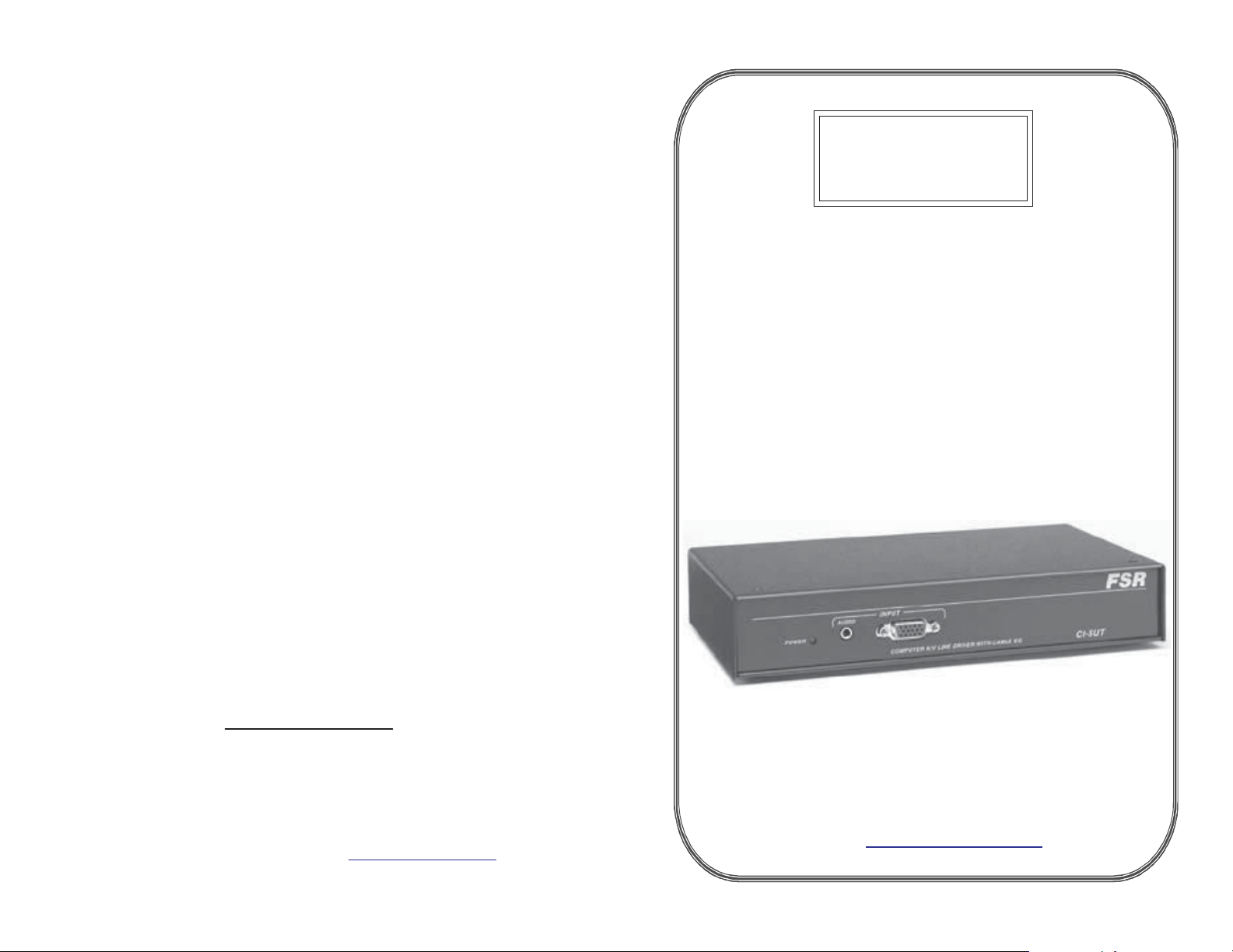
FSR
CI - 5UT
COMPUTER VIDEO and
STEREO AUDIO INTERFACE
OPERATIONS MANUAL
NOTE: all equipment being returned for repair must have a Return Authorization
(RMA) Number. To get a RMA Number, please call the
FSR Service Department (973-785-4347).
Please display your RMA Number prominently on the front of all packages.
Contact Information:
244 Bergen Boulevard,
West Paterson, NJ 07424
Tel: (973) 785-4347 · Fax: (973) 785-4207
E-Mail: [email protected] · Web: http://www.fsrinc.com
issue date: 9-16-02
244 Bergen Boulevard, West Paterson, NJ 07424
Tel: (973) 785-4347 · Fax: (973) 785-4207
E-Mail: [email protected]
Web: http://www.fsrinc.com
LIT1005$
Page 2

PROPRIETARY INFORMATION
All information in this manual is proprietary to and the
property of FSR inc. This publication is protected by the Federal
Copyright Law, with all rights reserved. No part
of this document may be reproduced, transcribed, or transmitted,
in any form or by any means, without prior
explicit written permission from FSR inc.
Operators Safety Summary
The general safety information in this summary is for operating
personnel.
Do Not Remove Covers or Panels There are no user-serviceable
parts within the unit. Removal of the top cover will expose
dangerous voltages. To avoid personal injury, do not remove the
top cover. Do not operate the unit without the cover installed.
Power Source This product is intended to operate from a power
source that will not apply more than 230 volts rms between the
supply conductors or between both supply conductor and ground.
A protective ground connection by way of grounding conductor in
the power supply is essential for safe operation.
Grounding the Product This product is grounded through the
grounding conductor of the power supply . T o avoid electrical
shock, plug the power supply into a properly wired receptacle
before connecting to the product input or output terminals. A
protective-ground connection by way of the grounding conductor
in the power supply is essential for safe operation.
Use the Proper Power Cord Use only the power supply, shipped
with and specified for your product. Use only a power cord that is
in good condition. Refer cord and connector changes to qualified
service personnel.
Do Not Operate in Explosive Atmospheres T o avoid explosion,
do not operate this product in an explosive atmosphere.
AUDIO INPUT
Number/type: 1 stereo unbalanced
Connectors: 3.5mm stereo mini connector
Impedance: 10K Ohms unbalanced
Max level: +6 dBm
AUDIO OUTPUT
Number/type: 1 Balanced Stereo (may be used in unbalanced
configuration)
Connector: 5 Position mini Phoenix
Impedance: 50 ohms
Maximum Level: 600 ohms: +12 dBm Balanced / +6 dBm
Unbalanced
Hi – Z: +14 dBm Balanced / +8 dBm Unbalanced
SYNC
Input level: 2.0 Vp-p to 5.0 Vp-p
Output level: 5.0 Vp-p into Hi-Z, 2.5 Vp-p into 75 ohm
Input Impedance: 475 ohms
Output impedance: 75 ohms
Polarity: Positive or negative
Horizontal frequency: 15 kHz - 200 kHz
Vertical frequency: 30 Hz - 150 Hz
POWER
Power: 9 VAC / DC, 50/60 Hz: 8 – 14 VDC,
9 VAC Power Supply included.
Mounting: 1/2 rack or under table (includes under
table brackets, 1/2 rack mount ordered
separately.
Enclosure T ype: Metal
Size: 8.5" W x 5.5" D x 1.5" H
Approvals: UL / CE
MH
100 ft
Page 3

TECHNICAL SPECIFICATIONS
INTRODUCTION
VIDEO INPUT
Number/type: 1 VGA / SVGA / XGA / SXGA / UXGA /
RGBHV / RGBS / RGsB / RsGsBs
Connectors: One 15 pin HD female
Level (nominal): Analog 0.7 Vp-p
Level (maximum): 2 Vp-p
Impedance: 75 ohms
EQUALIZED VIDEO OUTPUT
Number/type: 1 VGA / SVGA / XGA / SXGA / UXGA /
RGBHV / RGBS / RGsB / RsGsBs
Connectors: 5 female BNC’ s ( RGBHV )
Bandwidth: 400 MHz @ -3 dB
100' cable 180 MHz @ +/-0.5dB
150' cable 150 MHz @ +/-0.5 dB
Level (nominal): Unity / User adjustable via HI / LOW / OFF
Jumper
Gain: HI = 125’ to 175’, LOW = 60’ to 125’, OFF
= 0’ to 60’
Impedance: 75 ohms
Design Cable: W est Penn WP8255 or equal
LOCAL VIDEO OUTPUT
Number/type: 1 VGA / SVGA / XGA / SXGA / UXGA /
RGBHV / RGBS / RGsB / RsGsBs
Connectors: One 15 pin HD female
Bandwidth: 320MHz @ 03dB
Gain: Unity (buffered)
Impedance: 75 ohms
AUDIO
Bandwidth: 20 Hz to 20 kHz (+/-0.05 dB)
THD + Noise: 0.01% @ 20 kHz at rated Max Output S/N>98 dB
Noise Floor: < 98 dB
Stereo separation: -90 dB @ 1 kHz
Ideal for podiums and conference room settings, the FSR CI-5UT,
takes the worry out of signal loss due to long cable runs. The CI5UT interfaces with computer video and audio applications
providing signal amplification and balanced audio output for noisefree presentations.
The CI-5UT runs the computer video through an active line driver
equalized for the specific cable and sends it out through 5, high
resolution BNC connectors, eliminating signal loss in situations
where cable runs are more than 25 feet. A second fully buffered
out-put is available on a HD-15 connector for local monitoring.
The unbalanced stereo output is actively balanced to eliminate noise
and audio cross talk. It is then output to a 5 position Phoenix
connector.
The CI-5UT also functions as a universal interface when connected
to any FSR seamless switcher, allowing for one central connection
point for composite, S-V ideo component video and RGB.
The CI-5UT is designed with brackets to mount the unit under the
table which provides an unobtrusive way to hook up a laptop to a
presentaton system. Of course the unit can also be placed on the
table top.
If the CI-5UT is mounted under the table a more convenient way to
hookup a laptop (or equivalent device) would be to use the T-3U
T able Box with the pull out cable. This arrangement provides the
convience of the table top box with the advanced electronics of the
CI-5UT.
Page 4
SET UP and INSTALLATION
AUDIO
POWER
INPUT
COMPUTER A/V LINE DRIVER WITH CABLE EQ
Front view
CI-5UT
MOUNTING DETAIL
Un ba lanced Input Con ne ctor P in ou t
Ri ng = R ig ht
Tip = L ef t
Sl eeve = G nd
Ou tput Co nn ector W irin g
Ba la nced W irin g Un ba lanced W ir ing
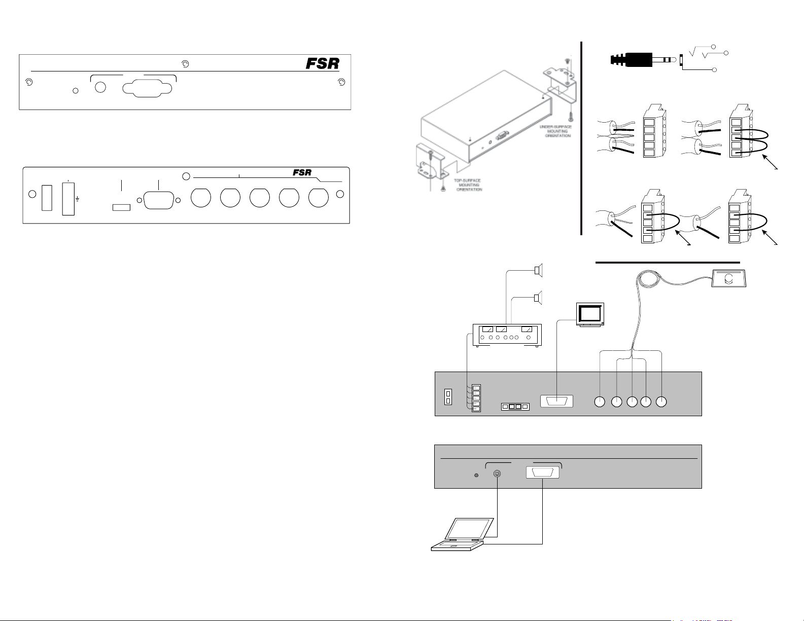
Connect laptop or similar device to the front of the unit.
Rear view
244 Bergen Blv d.
West Paterson,
N.J. 0 7424
V
Model C I-5UT
9VAC/DC
AUDIOPOWER IN
OUTPUT0.3A @
+
L
-
+
R
-
CABLE E Q
GAIN
O
LOFFIH
LOCAL MON ITOR
OUTPUT
VIDEO OUT PUT
GR
HB
The 5 BNC output cable, 9 VAC power supply leads and audio
leads should be prewired prior to completing the steps below. Do
not plug in the power supply until all wiring is completed.
Connect the 5 BNC female connectors to the 5 BNC male output
cable leading to the projector or monitor.
Connect the audio output cables to the captive screw terminals
labeled “Audio Out”. The appropriate wiring configuration for
balanced and unbalanced connections is shown on the next page.
Set the cable equalization jumpers for optimum performance at the
desired cable length (OFF=0-60', LO=60-125', HI=125-175').
TYPICAL INSTALLATION
AU DIO
AM PLIF IE R
POW ER IN
0.3A @9V AC
AUDIO
OUT PUT
CAB LE E Q
GAI N
+
L
-
H
I
+
R
-
O
F
FLO
LOC AL M ONIT OR
OUT PUT
Monit or
+
L
-
SH
+
R
-
M on o O utp ut C on necto r W iring
Ba la nced W irin g U nbal an ce d W ir in g
+
L
-
SH
+
R
-
UP TO 175' C AB LE RUN
R
VID EO O UTPU T
G
B
H V
FS R
+
L
-
SH
+
R
-
+
L
-
SH
+
R
-
Pro jecto r
Jumpe r
Jumpe rJumpe r
Connect the 9 VAC power supply output to the Power In connector
Confirm proper video and audio operation before mounting the CI 5UT
Use the supplied brackets to mount the CI - 5UT to the underside
or topside of the table.
Perform the final operational check.
INP UT
POW ER
Laptop
AUD IO
COM PUTE R A/ V LIN E DR IVER W IT H CA BLE E Q
CI-5U T COM PUT E R A/V L INE DRIVER
TY PICAL AP PL ICATIO N
FSR
CI-5 UT
 Loading...