

Page 1
244 Bergen Blvd. Woodland Park NJ 07424 973-785-4347 www.fsrinc.com
ELECTRICAL HOOKUP INSTRUCTIONS FOR CB-12 / CB-12P
CEILING BOX
WARNING: ENSURE BRANCH CIRCUIT POWER IS DISCONNECTED BEFORE
INSTALLATION.
NOT MEANT TO SUPERSEDE NEC OR LOCAL ELECTRICAL CODES.
INSTRUCTIONS FOR CONNECTION TO A 15 AMP BRANCH CIRCUIT:
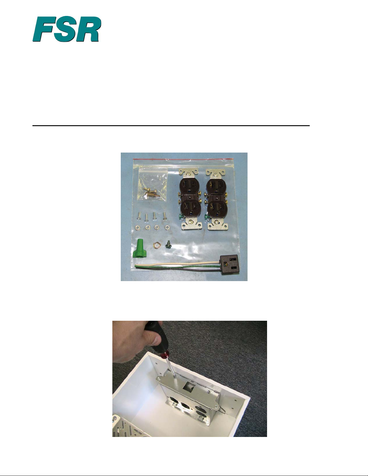
1) A bag of parts, as shown below, is provided with each housing.
THESE INSTRUCTIONS ARE INTENDED AS A GUIDE AND ARE
BAG OF PARTS INCLUDED WITH HOUSING
2) Remove the electrical box cover by removing the two retaining screws as shown in
Figure 1.Save all parts for later reassembly.
Figure 1
Page 1 of 4 43185 LIT1417
Page 2
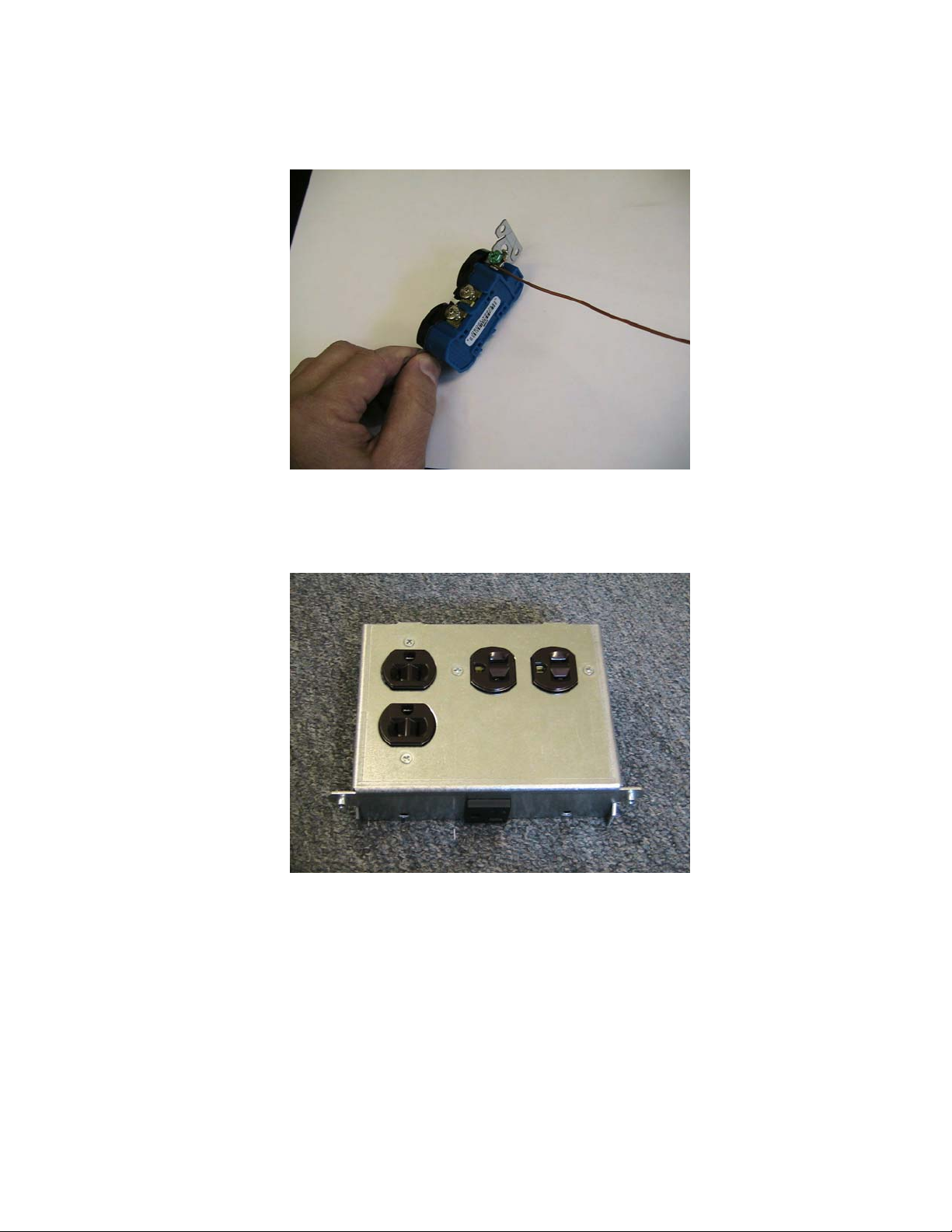
3) Prepare duplex receptacles (two provided) by installing a 6" length of bare #14 AWG
solid copper wire to the receptacle ground screw as shown in Figure 2. Tighten to
specifications.
Figure 2
4) Install duplex receptacles in electrical box cover using supplied hardware noting
orientation in Figure 3. Tighten all hardware to specifications.
Figure 3
Page 2 of 4 43185 LIT1417
Page 3

5) Install prewired single receptacle in electrical box cover by passing attached wires
through hole in cover and pushing fully into place. Note orientation of attached wires in
figure 4.
Figure 4
6) Push wire the single and duplex receptacles as shown in figure 4 using #14 AWG solid
copper wire, noting applicable strip lengths and polarity.
7) Bring a 14 AWG copper branch circuit feed wire in through desired k/o and attach with
appropriate clamp hardware. Un-sheath a suitable length (about 8-10") of wire.
8) Strip full length of insulation from the end of the branch circuit ground wire if it is
insulated, and pass wire through supplied green ground bond wire nut. Form a loop at
end of bare copper ground wire for attachment to chassis ground bond screw.
9) Strip 1" of insulation from the ground wire of the single receptacle. Join with the ground
wires of the two duplex receptacles while holding the ends even. Push firmly into the
green ground bond wire nut and twist in a normal manner, leaving about 2" from the
looped wire end to the ground bond wire nut as shown in figure 5.
Figure 5
Page 3 of 4 43185 LIT1417
Page 4

10) Attach the looped end of ground bond wire to the chassis ground screw as shown in
figure 6 and tighten to specifications.
Figure 6
11) Connect incoming branch circuit 14 AWG copper line and neutral conductors to
remaining push wire connection ports of duplex receptacle as shown in Figure 5. Note
applicable strip length and polarity.
12) Reinstall the electrical box cover, taking care not to trap wires between the cover and
the adjoining metal chassis. Reinstall and tighten the cover retaining screws removed in
step 1.
13) Restore branch circuit power and test the polarity of all receptacles.
Page 4 of 4 43185 LIT1417
 Loading...