

FSP Technology ZEN400 User Manual

INDEX
INDEX
Français
Deutsch
ᒅڎ
01~04
05~08
09~12
13~16
17~20
INDEX
1. Disconnect all mains power from the computer at the plug.
2. Remove the case/cover from your PC system.
3. Unplug all power connectors from the old power supply.
4. Remove the four screws from the rear of the case that hold the old power
supply to the chassis, then remove the old power supply from the case.
5. Screw the four screws into the rear of the case that hold the FSP power
supply to the chassis.
6. Reconnect all power connectors from the FSP power supply to the computer
components. The plugs will only fit one way, so if they don't fit, do not try
to force them, just try them the other way round.
7. Ensure no screws remain loose inside the casing as these could potentially
short-circuit your motherboard.
8. Replace the case/cover.
1 Installation Instructions
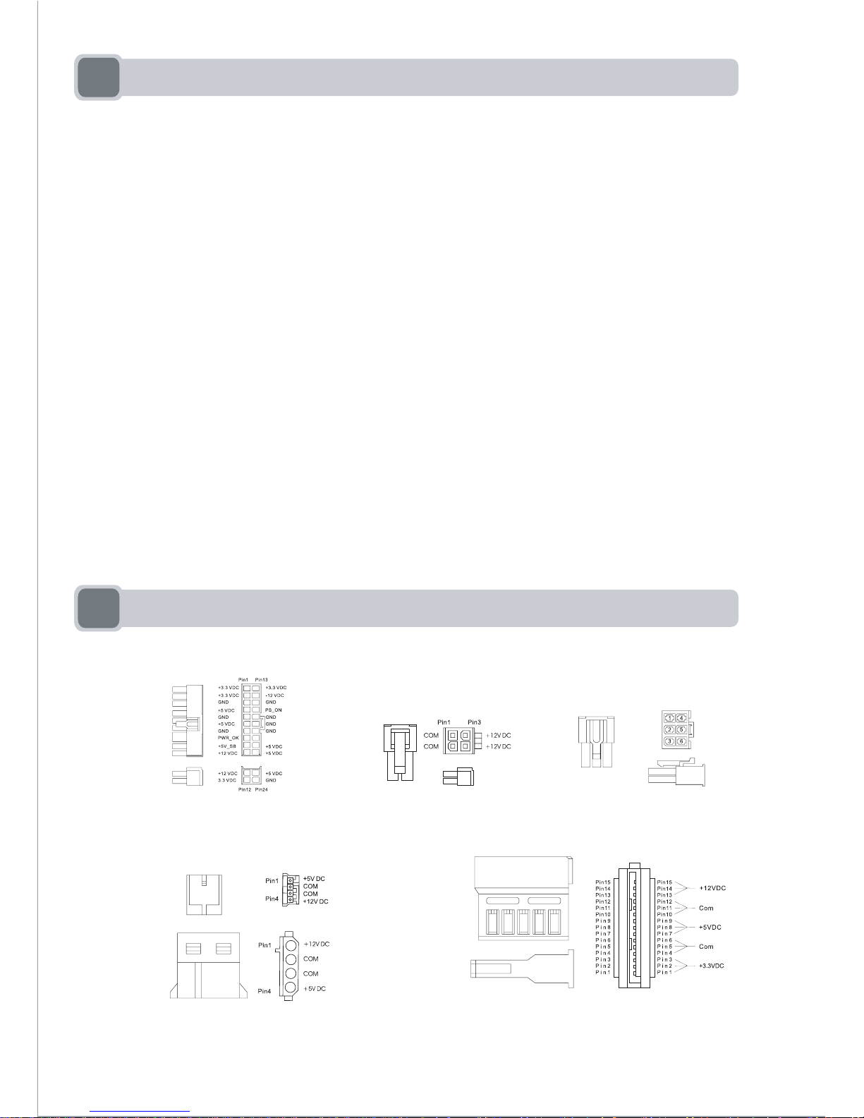
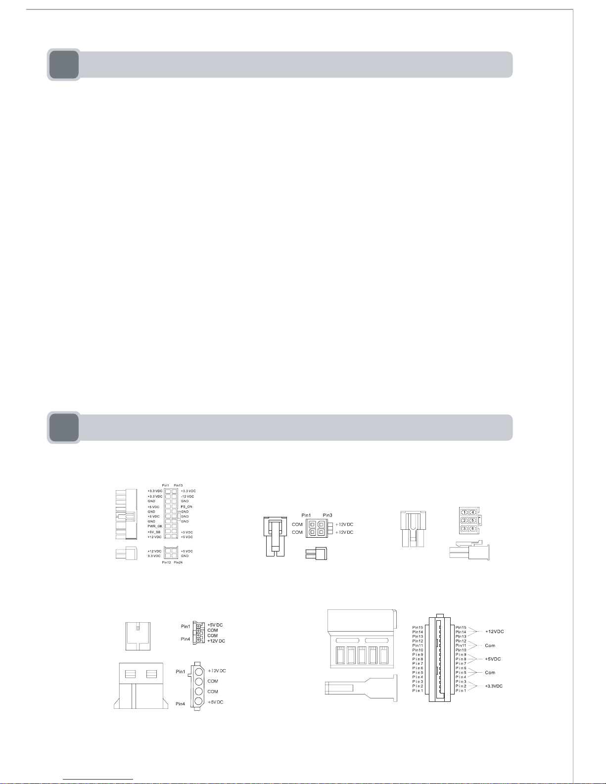
2 Description of Connectors
1
Peripheral power connector Serial ATA power connector
+12V power connectorMain power connector
+12V PCI Express
connector
Pin1 Pin2
+12VDC
+12VDC
+12VDC
COM
COM
COM
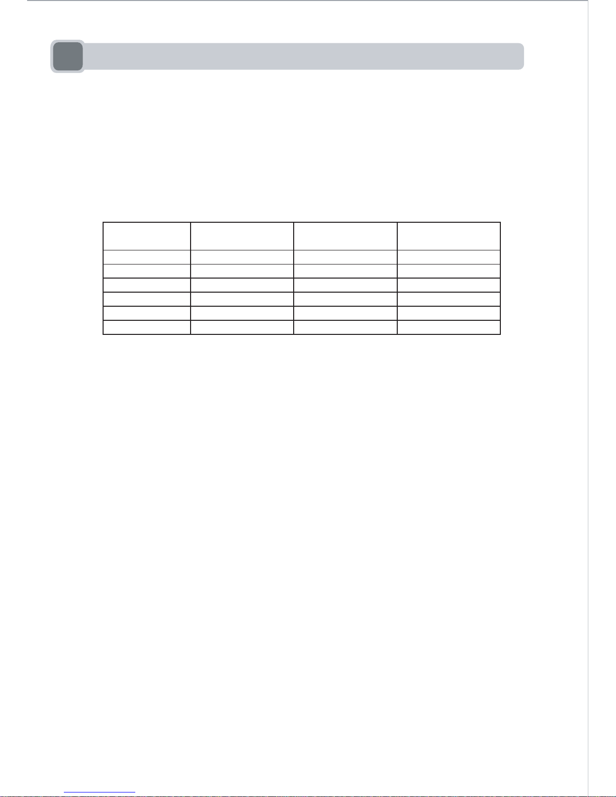
3 Electrical Specification
2
A. Input Voltage :
(1) Model : ZEN400 : 110VAC-240VAC (50Hz - 60Hz)
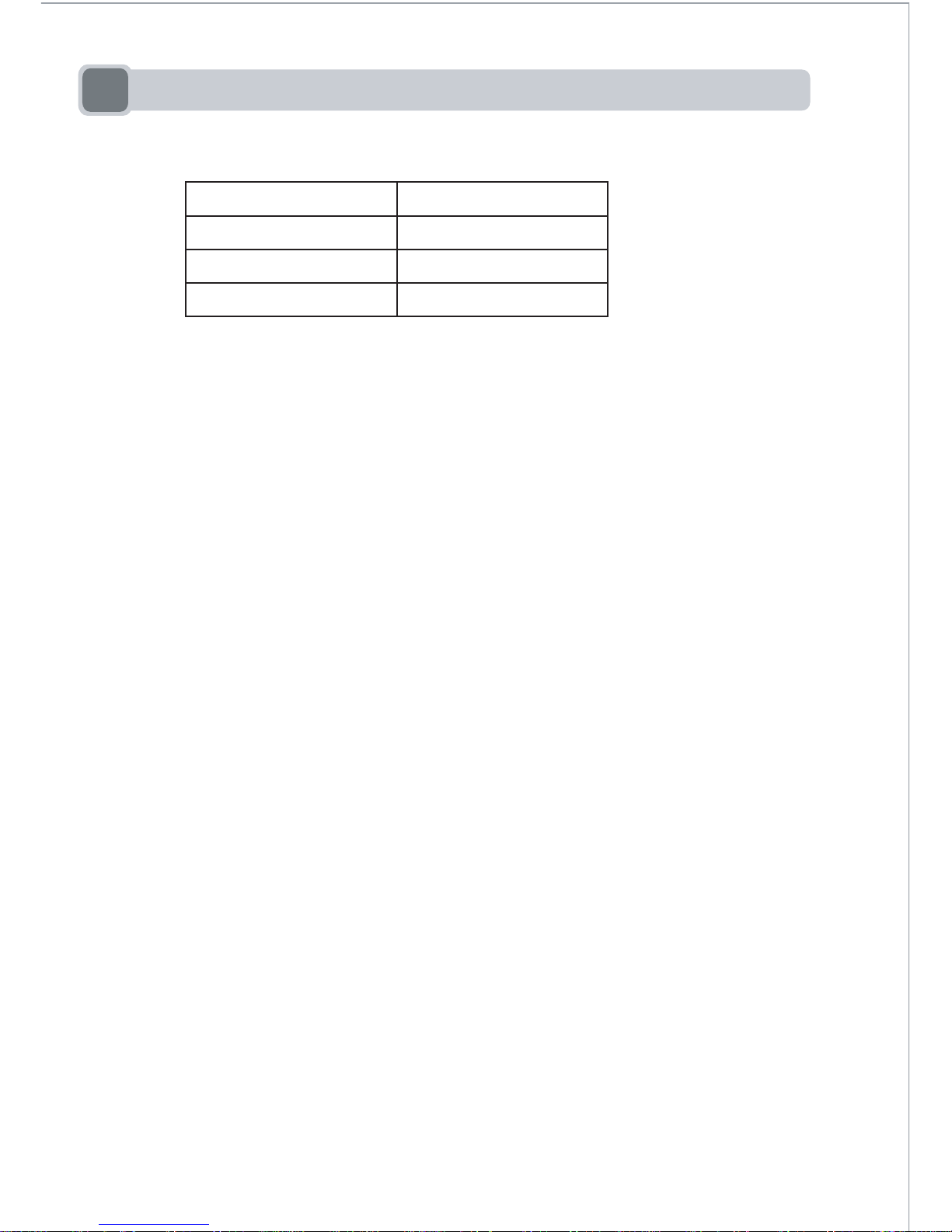
(1) Model : ZEN400
+3.3V 0.0A
20.0A
+5V 0.0A 14.0A
+12V1 0.2A 14.0A
0.2A 13.0A
-12V 0.0A 0.5A
+5Vsb 0.0A 2.5A
+12V2
MINIMUM
LOAD
NORMAL
LOAD
MAXIMUM
LOAD
OUTPUT
VOLTAGE
B. Output Voltage :
*All specifications are subject to our actual product
(1) The +3.3V and +5V total output shall not exceed 130W.
(2) Total output power max is 400W.
(3) Max peak power is 560W.
10A
7.0A
7.0A
6.5A
0.25A
1.25A
4 Protection
3
A. Over-Voltage Protection
B. Over-Current Protection
There will be protection from an output over-current event. The power supply
may shut down from such an event and require power-on restart.
C. Short-Current Protection
Output short circuit is defined to be a short circuit load of less than 0.1 ohm.
In the event of a short circuit condition on the +3.3V, +5V or +12V(-12V) output,
the power supply will shut down and latch off without damage to the power supply.
The power supply should return to normal operation after the short circuit has been
removed and the power switch has been turned off for no more than 2 seconds.
Voltage Source Protection Point
+3.3V
+5V
+12V 13.0V-16.5V
3.76V-4.8V
5.6V-7.0V

4
5 Safety and EMI
The power supply unit have been certified by the following safety and EMI
certifications:cUL, Nemko, CE, CB, GOST, FCC
6 Warning
(1) Do not open the top cover of the power supply unit !
(2) Please avoid exposing the power supply to high humidity.
7 Trouble shooting
If the power supply unit fails to function properly, please check the following:
Is the AC input plugged in properly and electrical outlet switched on?
Check that all the output connectors are connected properly to all the components.
Disconnection the power cord from the unit can reset the power supply unit
However, if the power supply still does not function properly, please contact
your original vendor or retailer for repair or replacement.
Please refer to the FSP website for further information:
www.FSP-group.com
1. Débranchez le câble secteur de l'ordinateur au niveau de la prise murale.
2. Démontez le couvercle/capot de votre système PC.
3. Débranchez tous les connecteurs d'alimentation de l'ancienne unité d'alimentation.
4. Dévissez les quatre vis sur l’arrière du boîtier qui fixent l’ancienne unité d’alimentation
au châssis, et ôtez l’ancienne unité d’alimentation.
5. Fixez l’unité d’alimentation FSP au châssis avec les quatre vis.
6. Reconnectez tous les connecteurs d'alimentation de l'unité d'alimentation FSP sur les
composants de l'ordinateur. Les fiches ne peuvent se brancher que dans un seul sens ;
si elles n'entrent pas, ne forcez pas, essayez simplement de les retourner.
7. Vérifiez qu'aucune vis ne reste dévissée dans le châssis, car toute vis dévissée risque
de provoquer un court-circuit sur votre carte mère.
8. Remettez le couvercle/capot en place.
1 Instructions d'installation
2 Description des connecteurs
5
Connecteur d'alimentation ATA sérieConnecteur d'alimentation périphérique
Connecteur d'alimentation +12VConnecteur d'alimentation principal
Connecteur d'alimentation
+12V PCI Express
Pin1 Pin2
+12VDC
+12VDC
+12VDC
COM
COM
COM
 Loading...