

FSP Technology Modbus Box Quick Manual
Modbus Box Quick Guide V.1.1
Thank you for purchasing Modbus box. This manual contains instructions and warnings that
should be followed during the installation, operating and storage of the card. Please keep this
manual for further reference.
Special Precautions
If the Modbus box must be stored prior to installation; storage must be in a dry place
The admissible storage temperature range is from -10ºC to +70ºC.
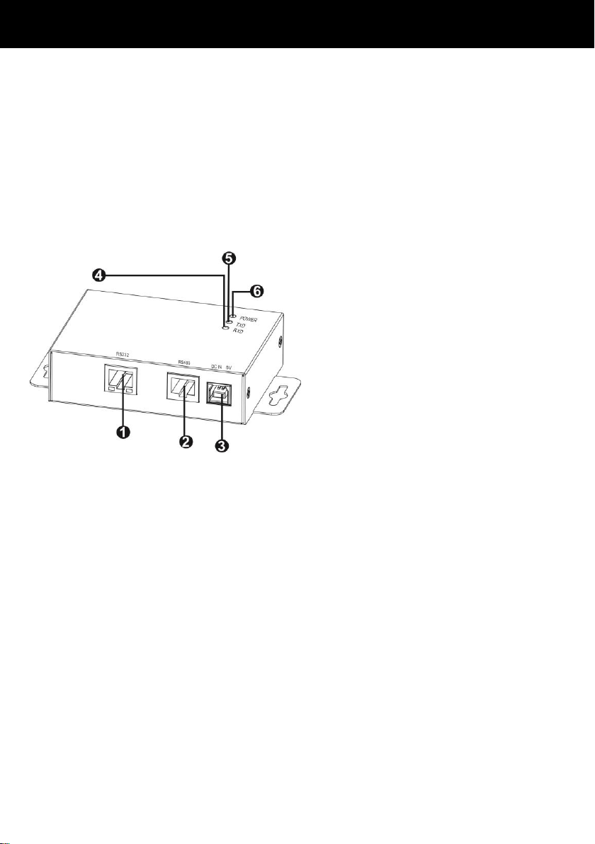
1. Product Overview
RS-232 port
RS-485 port
5V DC input
RS232 TXD LED
RS232 RXD LED
Power indicator
2. Product Introduction
The Modbus box provides inverter with the functionality of communication with PCs through
MODBUS protocol:
Implements MODBUS RTU protocol
Provides MODBUS functions including read Holding Registers and write Registers.
Provides RS485 interface
Provides surge protection
1
Modbus Box Quick Guide V.1.1
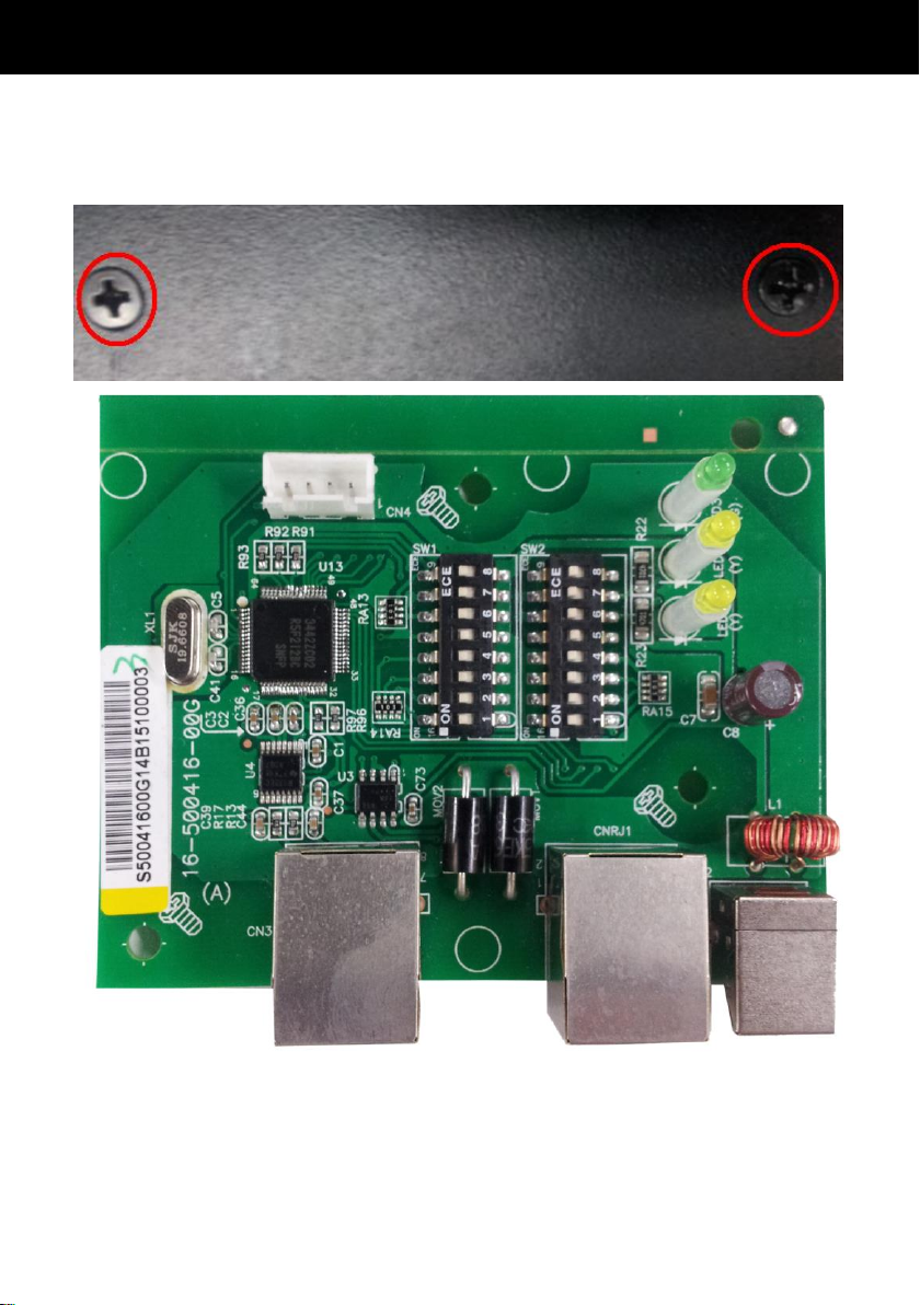
3. Installation and Operation
Follow below steps to install and use this modbus box:
1. Remove top case by removing screws. See below chart.
2. Configure Modbus ID (Refer to section 4.1 for the details).
3. Configure communication format (Refer to section 4.2 for the details).
4. Connect modbus box to inverter with RS232 cable.
5. Connect modbus box to RS-485 adapter with RJ45 cable.
2
Modbus Box Quick Guide V.1.1
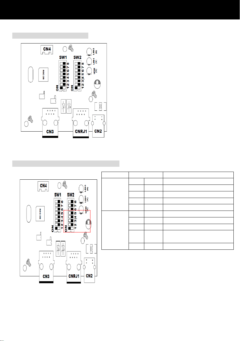
Function
Bit Setting
Meaning
Baud
rate
# 2
# 1
OFF
OFF
2400bps
OFF
ON
4800bps
ON
OFF
9600bps
ON
ON
19200bps(default)
Parity
check
# 4
# 3
OFF
OFF
Even parity
ON
OFF
Odd parity
OFF
ON
No parity check 1 stop bits
(Default)
ON
ON
No parity check 2 stop bits
There are eight bits to present ID of each card.
Use SW1 to set machine ID. From left to right, it’s
8 to 1. As shown, when the switch is pushed
down, the bit is set to “one”. Otherwise, the bit is
set as zero. The ID of modbus card is set to 0x01
as chart. Please check appendix for detailed ID no.
and SW1 setting.
4. Configuration
4.1 Machine ID Configuration
4.2 Communication Format Configuration
3
Modbus Box Quick Guide V.1.1
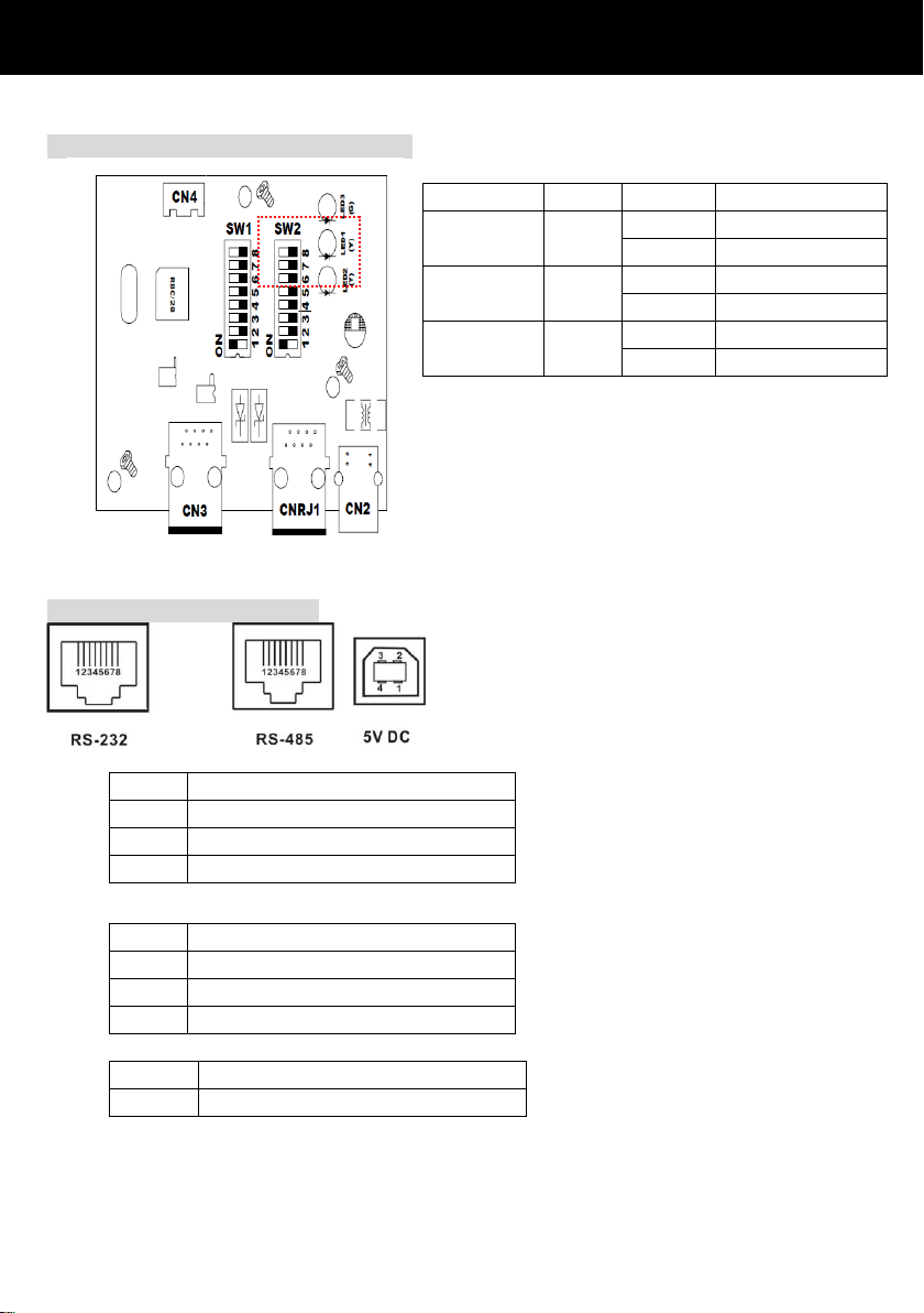
Pin
Function
4
RS-485 - B
5
RS-485 - A
8
GND
Pin
Function
1
Txd
2
Rxd 8 GND
Voltage
5V DC
Current
500 mA
Function
Bit #
Setting
Meaning
Push up
resistance
# 6
ON
Enable (Default)
OFF
Disable
Push down
resistance
# 7
ON
Enable (Default)
OFF
Disable
Terminate
resistance
# 8
ON
Enable (Default)
OFF
Disable
4.3 RS-485 Resistance Configuration
4.4 Interface Configuration
RS-485 Pin Configuration
RS232 Pin Configuration:
USB spec
USB port is used as input power source, not for communication purpose.
4
 Loading...