

FSP Technology EMERGY 1000, EMERGY 3000 User Manual
Please read this User Manual first before Operating the System.
EMERGY 1000
User Manual
-

Table of Contents
1. ABOUT THIS MANUAL - 2 -
1.1 Additional Information - 2 -
1.2 Symbol Used - 2 -
2. PRODUCT OVERVIEW - 3 -
2.1 Appearance and Functions - 3 -
2.2 Gauge/Charging Indicators and Alarm - 4 -
3. SYSTEM OPERATIONS - 7 -
3.1 Turning On/Off System - 7 -
3.2 Charging System - 7 -
3.3 System Outputs - 9 -
3.4 Operating Modes - 9 -
3.5 Physical Positioning - 10 -
3.6 Apparatus/Equipment/Appliances - 10 -
4. TRANSPORTATION - 12 -
5. STORAGE - 13 -
6. IN CASE OF EMERGENCY - 14 -
7. MAINTENANCE - 14 -
8. WARRANTY - 15 -
- 1 -
1. About this Manual
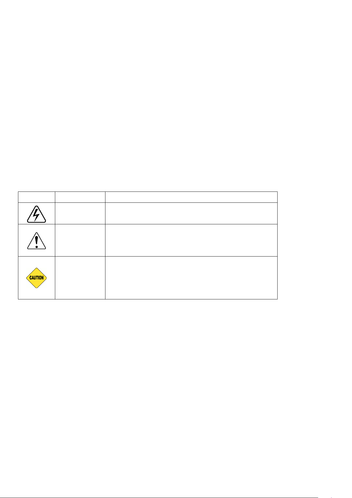
Symbols
Meaning
Description
DANGER
Beware dangerous voltage.
WARNING
It calls attention to a procedure, practice, or the like,
which, if not correctly performed or adhered to, could
result in personal injury.
CAUTION
It calls attention to an operating procedure, or the
like, which, if not correctly performed or adhered to,
could result in damage to or destruction of part or
all of the products.
This User Manual is for use with EMERGY 1000. User must refer to the User Manual before using
to avoid abnormal situations.
1.1 Additional Information
(1) The information in this document is subject to change without notice.
(2) Specification of the product can be changed without any notice to customers for the system
improvement.
(3) All rights reserved. Reproduction, adaptation, or translation of this document without prior
written permission is prohibited, except as allowed under the copyright laws.
1.2 Symbol Used
- 2 -
2. Product Overview
EMERGY 1000 is All-in-One Energy Storage System that integrate Li-Ion Battery System, Battery
Management System, AC charger, Photovoltaic (PV) charger, DC to AC inverter, System Control
into the compact & portable suitcase.
2.1 Appearance and Functions
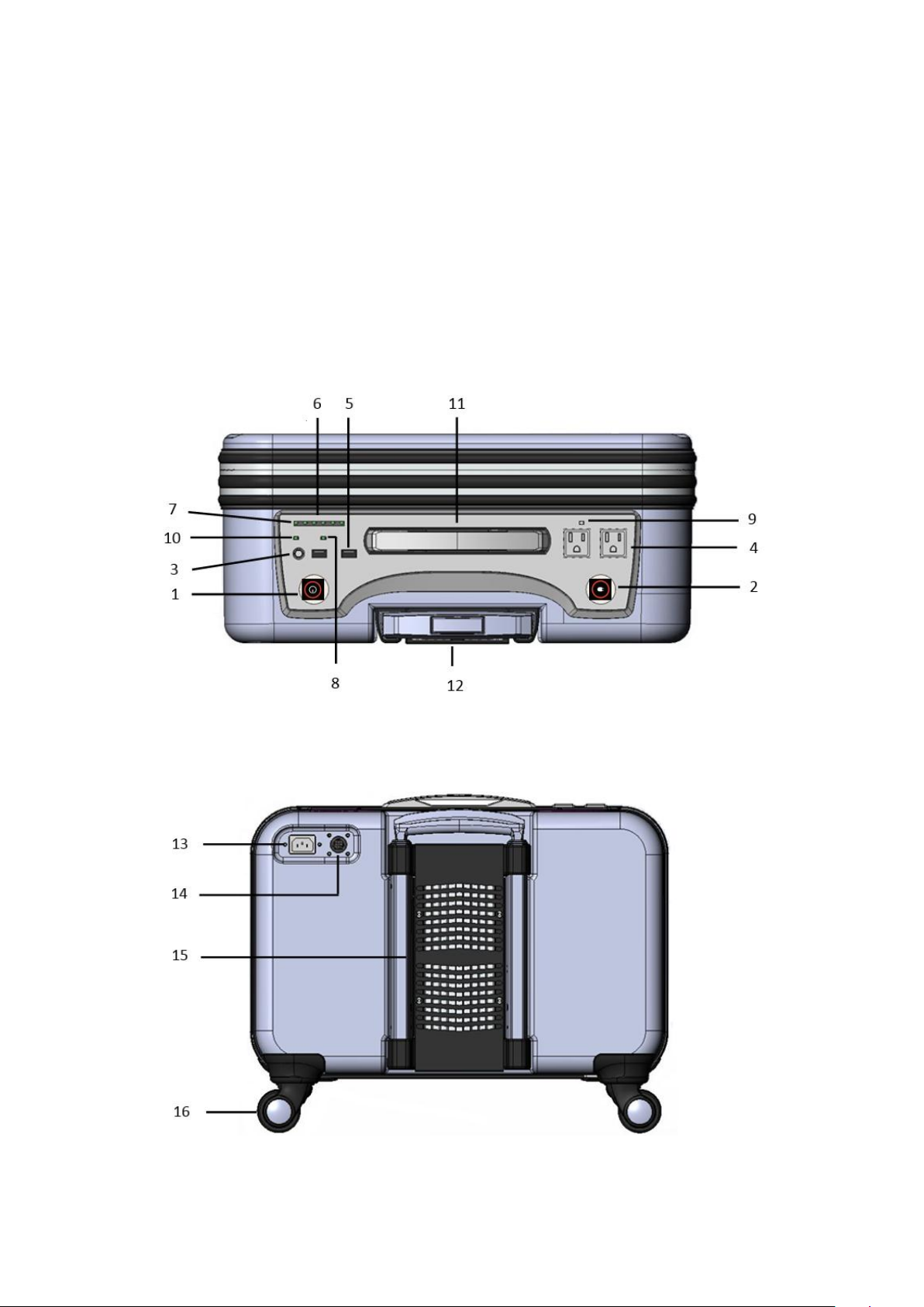
Figure 1 illustrates the appearance and key external parts in EMERGY 1000 . The functions of
each key parts are highlighted in Table 1.
Figure 1(a). Top View
Figure 1(b). Rear View
- 3 -
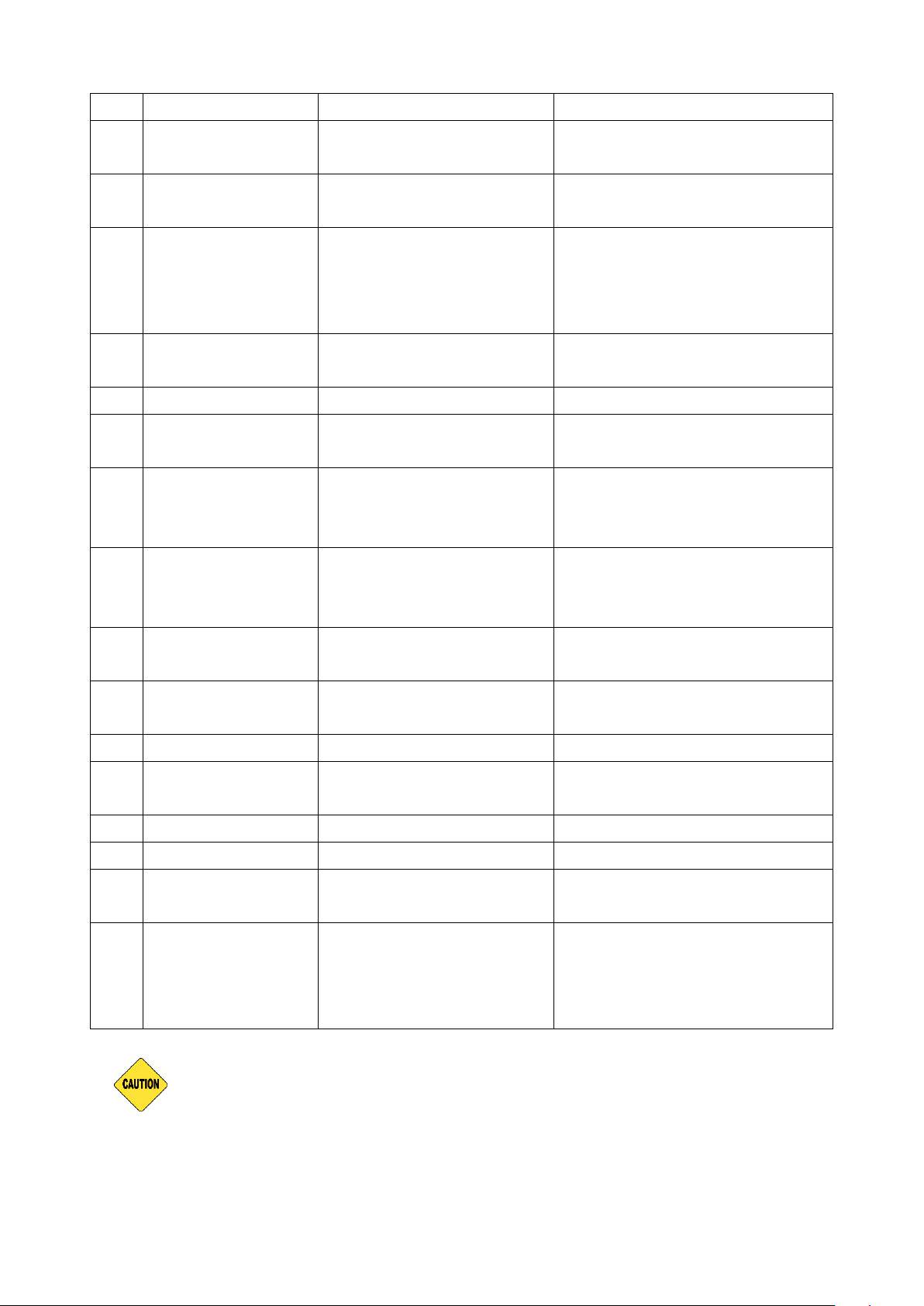
Table 1. Key External Parts and Functions
Item
Name
Function
Notes
1
MSW (MAIN
CONTROL SW)
Switch ON/OFF the
system
Hard press MSW to toggle
system ON/OFF.
2
AC OUT SW
Switch ON/OFF AC output
Hard press AC OUT SW to
toggle AC output ON/OFF.
3
MODE
Select Standby or On-Line
Operating Mode
Typical transfer time for
Standby Mode is 16mS. No
transfer time (0mS) for On-Line
Mode.
4
AC OUT
AC output(s)
AC socket(s) varies with
country.
5
5V USB OUT
USB Power Sources
Total current rated at 2A.
6
GAUGE
INDICATOR
Display State Of Charge
(SOC) of Li-Ion batteries
(Please see Table 2)
7
CHARGING
INDICATOR
Indicate charging state of
the battery
With a lightening mark under
CHARGING INDICATOR.
(Please see Table 3)
8
SYSTEM
INDICATOR
System status indication
USB power outlet is synched
with system power.
Light up when power is present.
9
AC OUT
INDICATOR
AC output power
indication
Light up when power is present.
10
MODE
INDICATOR
Indicate operating mode
Light up for On-Line Mode.
Turn off for Standby Mode.
11
LIFT HANDLE
For Lifting EMERGY 1000.
12
PULL HANDLE
For pulling/ pushing the
system while on wheels.
Not for lifting EMERGY 1000.
13
AC INLET
AC Input connection
(Please see paragraph 3.2.1)
14
PV INLET
AC Input connection
(Please see paragraph 3.2.2)
15
HEAT SINK
For heat dissipation
Blockage of heat sink area may
impede system performance.
16
WHEELS
For carrying system along
flat or smooth surface.
Please see Figure 6 to know
the locking mechanisms are
provided in the two front
wheels.
DO NOT use PULL HANDLE, but LIFT HANDLE to lift up EMERGY 1000 to
avoid damage to the system.
2.2 Gauge/Charging Indicators and Alarm
- 4 -
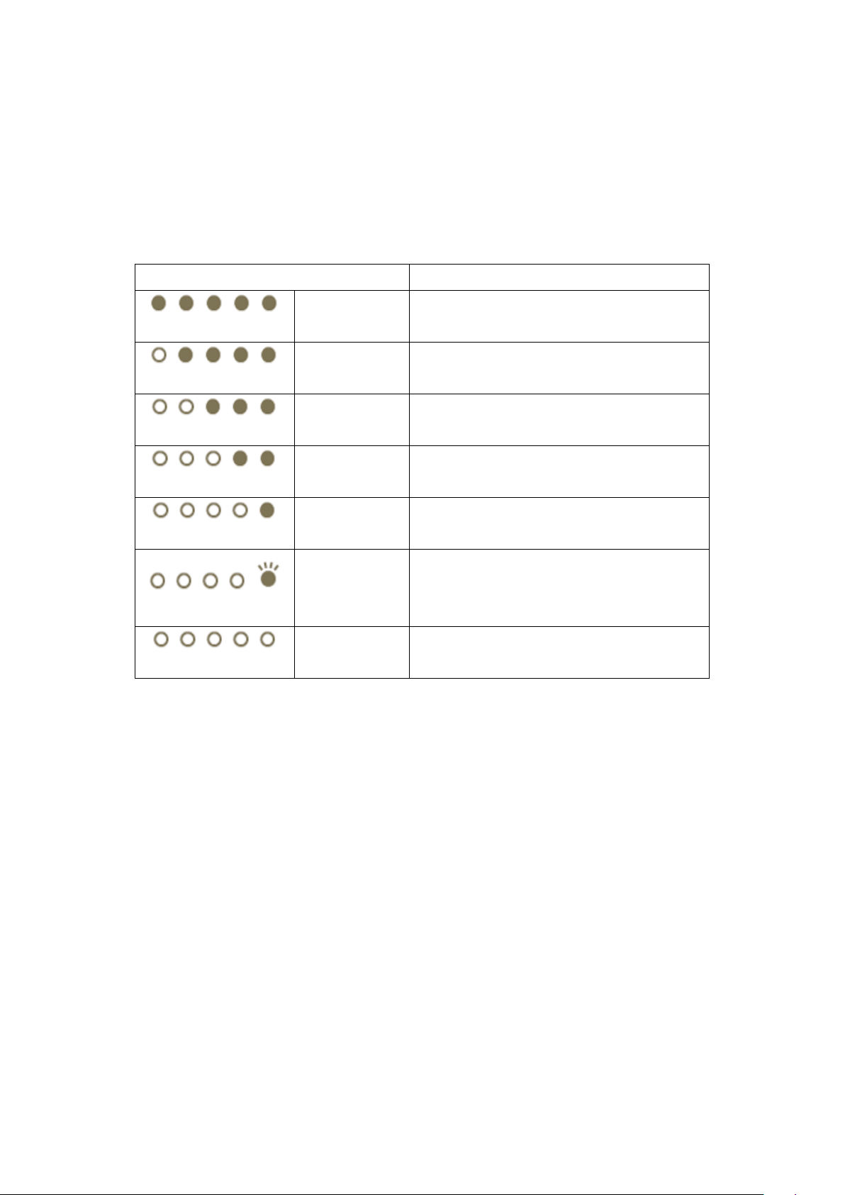
2.2.1 Gauge Indicator
Status
Meaning
5 LEDs On
(GGWOR)
SOC > 80%
4 LEDs On
(GGOR)
SOC between 60-80%
3 LEDs On
(GOR)
SOC between 40-60%
2 LEDs On
(OR)
SOC between 20-40%
1 LED On
(R)
SOC between 10-20%
(Charge Soon)
1 LED
blinking
(R)
SOC between 0-10%
(Charge Immediately)
All LEDs Off
MSW is off or battery fully drained.
F 3/4 H 1/4 E
F 3/4 H 1/4 E
F 3/4 H 1/4 E
F 3/4 H 1/4 E
F 3/4 H 1/4 E
F 3/4 H 1/4 E
F 3/4 H 1/4 E
The State Of Charge (SOC) or remaining capacity of the battery is illustrated thru five (3 green, 1
orange, 1 red) LED indictors on its face panel. From right to left each additional indicator
corresponds to about 20% additional battery capacity as illustrated in Table 2.
Table 2. Gauge Indicators
- 5 -
 Loading...