

Page 1

Installation Manual
Page 2

Page 3

WARNING!
This equipment generates, uses and radiates radio frequency energy and if not installed and used as
designed and intended, may cause interference to radio communications. This equipment has been
tested and found to comply with limits for a Class B computing device. This equipment has been
designed to provide reasonable protection against such interference when operated in residential, light
industrial, and commercial environments. Operation of this equipment in residential area may cause
interference, in which case the user, at their own expense, is required to take whatever measures are
needed to correct the interference.
USA - FCC
This device complies with Part 15 of the FCC Rules. Operation is subject to the following two
conditions: (1) This device may not cause harmful interference, and (2) This device must accept any
interference received, including interference that may cause undesired operation.
Canada – ICES - 003
This Class B digital apparatus meets all requirements of the Canadian Interference-Causing Equipment
Regulations.
Cet appareil numerique de la classe B respecte toutes les exigencies du Reglement sur le materiel
brouilleur du Canada.
European Community – EMC
This device complies with Class B emission limits in accordance with EN55022.
SPECIFICATION EC DIRECTIVE
Electromagnetic compatibility – Emissions 89/336/EEC
Electromagnetic compatibility – Immunity 89/336/EEC
Page 4
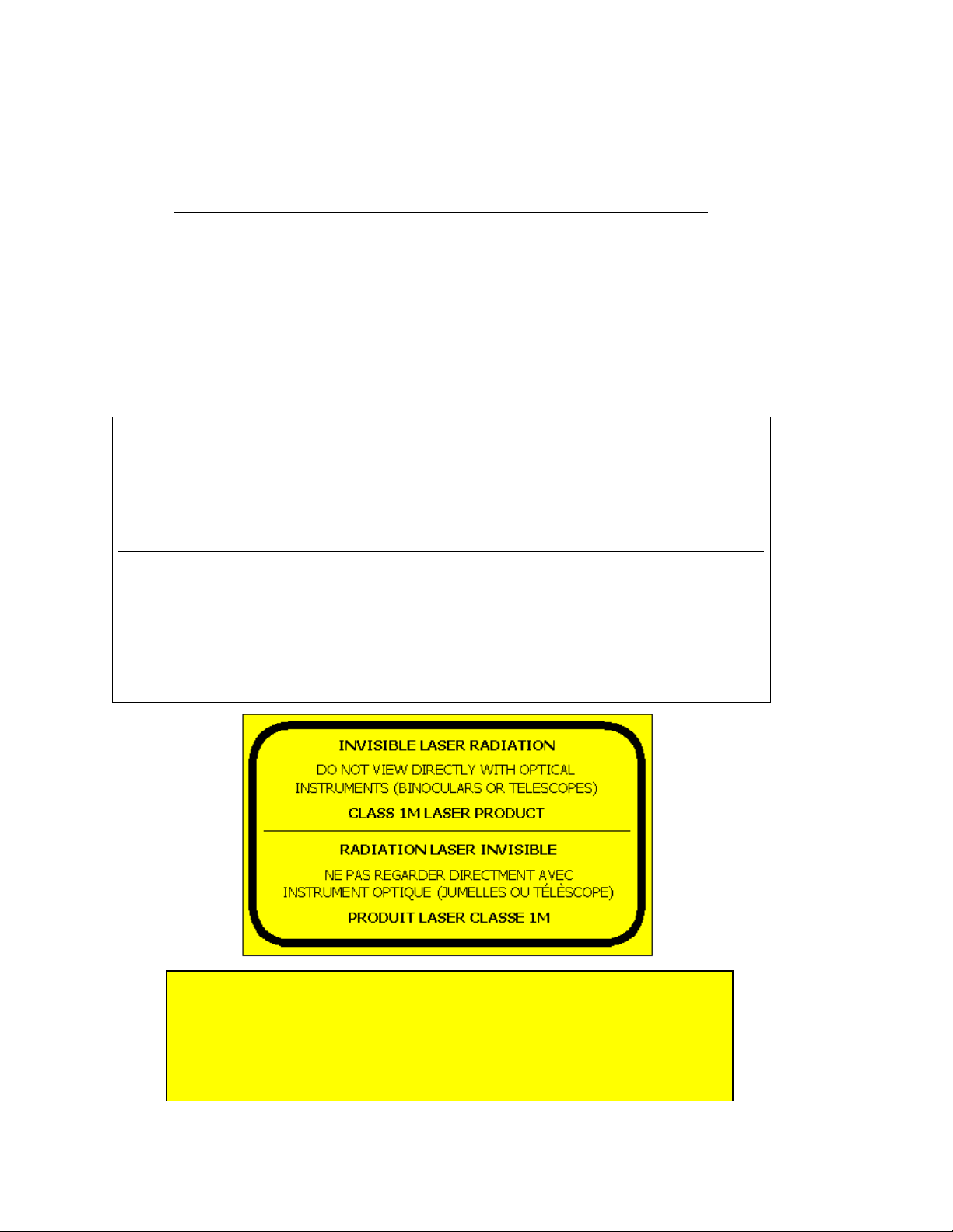
WARNING!
CAUTION: USE OF CONTROL OR ADJUSTMENTS OR PERFORMANCE OF PROCEDURES
OTHER THAN THOSE SPECIFIED HEREIN MAY RESULT IN HAZARDOUS LASER
RADIATION EXPOSURE!
ATTENTION: LE CONTROLE ET L’ADJUSTEMENT AINSI QUE LA MODIFICATION DES
PERFORMANCES AUTRES QUE CEUX STIPULÉS DANS CE MANUEL PEUVENT CRÉER
DES EFFETS IMPRÉVUS DE LA RADIATION LASER!
Product Laser Safety
The following special notes provide laser safety specifications for the SONAbeam E – Series terminal:
INFORMATION ALERT!
THE LASER DEVICES PRESENT WITHIN THIS EQUIPMENT ARE HAZARDOUS WHEN VIEWED
WITH OPTICAL INSTRUMENTS (BINOCULARS OR TELESCOPES). BOTH LASER
TRANSMITTERS HAVE THE FOLLOWING OUTPUT CHARACTERISTICS:
Laser Type Wavelength Avg. Output Power Peak Output Power
InGaAsP Laser Diode 1520 – 1580 nm 80 mW 160 mW
(Indium Gallium Arsenide Phosphide)
ALL SONAbeam models are:
ANSI-CLASS 1 laser product – According to ANSI Z136.1 & Z136.6
IEC-CLASS 1M laser product – According to IEC60825-1 Amendment 2:2001
CDRH-CLASS IM laser product – Complies with 21 CFR 1040.10 and 1040.11 except for deviations
pursuant to Laser Notice No. 50, dated July 26, 2001
WARNING: Optical viewing aids such as binoculars and telescopes must not
be positioned in front of this equipment at a range closer than 35m (115ft).
Link deployment conditions must be reviewed to ensure the use of optical
aids within the 35m zone is not a reasonably foreseeable event.
NOTE: The alignment telescope provided by fSONA has a special spectral
filter to allow safe operation.
Page 5

© 2003 - 2013 fSONA Networks Corp. ALL RIGHTS RESERVED
This Installation Manual is furnished under license and may be used or copied only in accordance with the
terms of such license. The content of this guide is furnished for informational use only, is subject to change
with out notice, and should not be construed whatsoever as a commitment by fSONA Networks Corp.
fSONA Networks Corp. assumes no responsibility or liability for any errors or inaccuracies that may appear in
this manual.
The fSONA LOGO and SONAbeam are trademarks of fSONA Networks Corp.
Other names of products are trademarks or registered trademarks of their respective owners.
Document No. 95-0224 Rev H November 2013
Printed in Canada.
Contacting Us
fSONA Networks Corp.
100 – 13200 Delf Place
Richmond, BC Canada V6V 2A2
Phone: (604) 273 6333
Fax: (604) 278 6340
Web: www.fsona.com
Page 6

Page 7

-
Series Installation Manual
Contents
Contents
About This Manual ........................................................................... 1
How this Manual is Organized 1
Conventions Used in this Manual 2
Safety First! 2
Installation Quick Sheet 2
Product Labeling 3
About Your SONAbeam Terminal ....................................................... 5
Preparing Your Installation Site ......................................................... 7
Locating Your SONAbeam Terminals 7
Site Safety 8
Site Accessibility 8
Site Security 8
Site Stability 9
East-West Orientation 9
Accessibility to Power, Ground and Communications Feeds 9
Line of Sight Clarity 10
Generating a Rooftop Site Map 10
Terminal Mounting Options 11
Pole/Wall Mount 13
Pedestal Mount 14
Customer Fabricated Mount 14
SONAbeam Power Requirements 16
wireless at the speed of light ……………. i
Page 8

Contents
DC Power Source 17
AC Power Source 17
SONAbeam Safety Certification 18
Power Over Ethernet 19
SONAbeam Fiber Requirements 20
Customer Interface Box 21
Additional Considerations 21
Unpacking Your SONAbeam Terminal .............................................. 23
The Product Package 23
Optional Accessories 25
Unpacking the Optical Head 27
Unpacking your Installation Kit 27
Installing Your SONAbeam Terminal ................................................ 29
Safety First, Safety Always 29
Before You Begin… 29
Required Tools and Accessories 30
Installing the (Optional) Pole Mount 30
Installing the (Optional) Pedestal Mount 32
Installing the Optical Head 32
Customer Interface Connections 33
Optional Customer Cabling Kit 34
SONAbeam Customer Interface Area 34
E-Series Customer Interfaces 38
Power Connections 39
Network Communications Cables 41
-Series Installation Manual
ii wireless at the speed of light …………….
Page 9

Contents
-
Series Installation Manual
Terminal Management Connections 43
Terminal Mgmt RS232 Interface 44
Strain Relief for your Interface Cabling 45
Connections at the Customer Interface Box 46
Initial Power Up and Terminal Configuration .................................... 47
SONAbeam Utilities CD 48
SONAbeam Terminal Controller Software 48
Connecting a PC to your SONAbeam Terminal 49
USB Connection 49
RJ45 Serial Adapter 50
SONAbeam Terminal Power Up 50
Verifying Initial Power Up Operation 51
SONAbeam Terminal Status LED’s 51
Verifying Power Up Operation with STC 52
Setting Up your SONAbeam Terminal 52
Initial Configuration Wizard 53
SONAbeam Diagnostics 54
SONAbeam Transmitter Orientations 54
Network Connection for Alignment 55
Aligning Your SONAbeam Terminals ................................................ 57
Before You Begin… 57
Alignment Adjustments 58
Coarse Azimuth Adjustment 58
Coarse Elevation Control 59
Fine Azimuth & Elevation Tuning 60
Stage 1 – Visual Alignment 61
wireless at the speed of light ……………. iii
Page 10

Contents
Stage 2 – Finding your FSO Signal 63
Stage 3 – Fine Tuning your Alignment 66
Received Signal Strength Guide 68
Stage 4 – Locking your Final Alignment 69
Completing the Installation 70
Deploying Your SONAbeam Link...................................................... 73
Putting SONAbeam Link to Work 73
System Problems ........................................................................... 75
-Series Installation Manual
iv wireless at the speed of light …………….
Page 11

About This Manual
About This Manual
This manual is designed for system integrators and installers of fSONA’s SONAbeam
optical communications terminal to help plan, install and commission robust, very high
speed wireless optical communications links.
How this Manual is Organized
This manual covers a wide scope of material from initial planning and site surveying,
through installing and commissioning high speed, wireless optical communications links.
In order to better present such information, this manual is divided into seven major
sections to individually address each stage:
About Your SONAbeam Terminal
This section provides an overview of the SONAbeam communications link
and presents a general picture of the overall system installation and its
interfaces…
Preparing Your Installation Site
This section provides valuable information to better prepare for your
installation. With the information presented here, you can reduce (if not
eliminate) a number of problems and help ensure a successful installation…
Unpacking Your SONAbeam Terminals
This section describes what will be received from fSONA and identifies
what you will need to provide in order to complete the installation…
Installing Your SONAbeam Terminals
This section provides a step-by-step procedure describing the physical
installation of SONAbeam terminals and their interfacing connections. A
pre-power up check list is also presented…
Initial Power Up and Configuration
This section describes the initial power up sequence and how to configure
your SONAbeam for your network operations…
Aligning Your SONAbeam Terminals
This section describes how to precisely align a pair of SONAbeam
terminals for optimal performance…
Deploying your SONAbeam Link
This section describes the final steps of deploying your SONAbeam link…
wireless at the speed of light …………….
1
-Series Installation Manual
Page 12
About This Manual
Conventions Used in this Manual
Throughout this manual, certain items of particular importance will be presented in the
following formats:
NOTE…
This format offers useful or advisory information to help make your installation a
success…
WARNING!
This format warns of safety related issues as well as practices and situations that
need to be avoided…
Safety First!
When properly installed, SONAbeam terminals will provide safe and reliable operation.
To ensure a safe and proper installation, the following items are considered mandatory:
Your installation MUST be well planned and implemented without shortcuts…
Your installation MUST be supervised and performed by qualified persons…
Your installation MUST comply with all local worker safety codes…
Your installation MUST comply with all local electrical safety codes…
WARNING!
Failure to adhere to these ‘common sense’ requirements can result in injury to
persons and/or damage to property and/or equipment!
Installation Quick Sheet
Your new SONAbeam also includes an installation
contents of this installation manual.
While it is important that you read and understand the entire installation manual before
attempting to install your SONAbeam link, the
guide to the installation process.
QUICKSHEET
QUICKSHEET
that summarizes the
offers a handy reference
NAbeam E-Series Installation Manual
2
wireless at the speed of light …………….
Page 13
Product Labeling
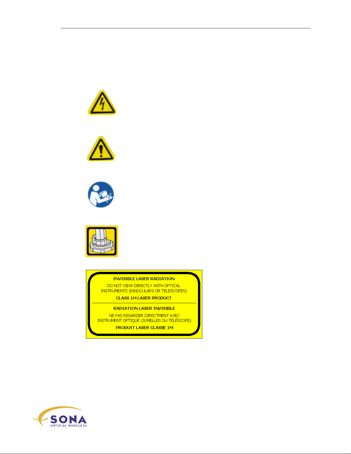
The SONAbeam terminal is labeled with the following symbols:
WARNING: Electrical Hazard –
Dangerous high voltage is present
inside that could result in injury or
death to personnel…
CAUTION: Damage to the equipment
or Injury to the operator may occur
if procedures are not followed…
ATTENTION: Read the Installation
Manual before attempting to install
the equipment!
About This Manual
NOTE: The Alignment Telescope – provided as part of the SONAbeam Basic
Alignment Kit – has a special spectral filter installed to make it safe to use with
SONAbeam products.
USE THE STRAIN RELIEF to secure
your terminal cabling!
IEC60825-1 Classification
Label – Class 1M laser
Product…
wireless at the speed of light …………….
3
-Series Installation Manual
Page 14

About This Manual
NAbeam E-Series Installation Manual
4
wireless at the speed of light …………….
Page 15
About Your SONAbeam Terminal
About Your
SONAbeam Terminal
The SONAbeam E-Series terminal is an extremely reliable, very high speed, full-duplex,
wireless component for your communications network employing multiple, infrared, eyesafe laser transmitters, a large-aperture optical receiver and an embedded microprocessor.
SONAbeam terminals are designed to operate equally well either indoors or outdoors
where a clear and unobstructed “line-of-sight” exists between two connecting points in a
network, with link distances from as close as 50 meters (100 feet) to as far away as
several kilometers in clear-air conditions, depending on the model deployed.
Designed to accept a variety of userspecified interface and power supply
modules, your SONAbeam E Series
terminals can be used to
accommodate a variety of data and
video transport needs. While actual
usable data rates are option
dependent, the E-Series terminal can
be used to transport 1.5 – 160 Mbps
and supports a range of
communication standards including:
T1/E1, E3/DS3, 10/100 Ethernet,
OC-1/STM-0 and OC-3/STM-1 as
well as SMPTE and HDTV video
transmission standards.
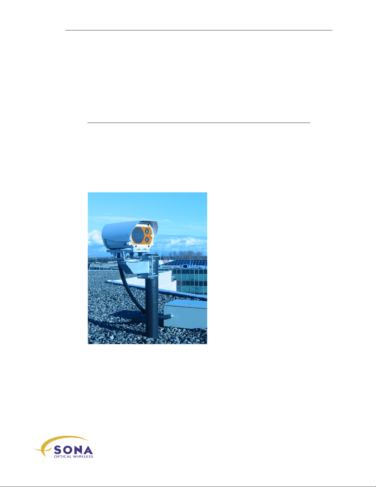
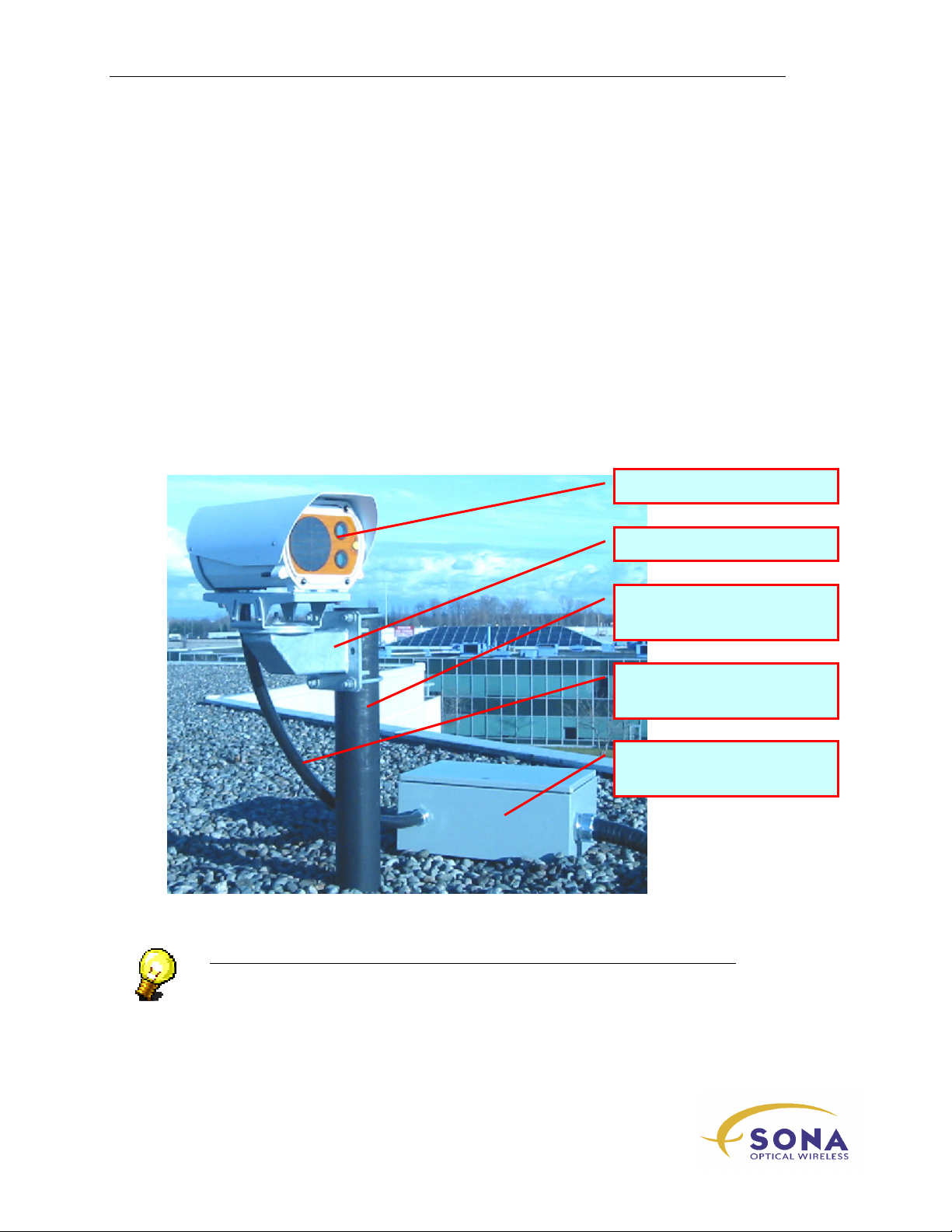
Figure 1- A Typical E-Series
SONAbeam Installation
With Integrated Network Management (INM), your SONAbeam terminals can be
connected to your business LAN to allow you to monitor and manage your terminals
from your office computer. Add the optional embedded SNMP agent to your SONAbeam
terminals and you can manage your entire network of SONAbeam FSO links from your
(SNMP) Network management System.
Each SONAbeam E-Series terminal employs multiple high power, high bandwidth, eyesafe 1550nm lasers integrated with a patented optical receiver system to achieve superior
data performance in all weather conditions. The SONAbeam E-Series terminal is a carrier
wireless at the speed of light …………….
5
-Series Installation Manual
Page 16
About Your SONAbeam Terminal
class device that offers protocol independent optical interfaces that are unmatched in the
industry.
With proper planning and pre-installation preparation, a complete network link can be
installed and commissioned in a matter of hours and provide lasting reliable operation to
meet your networking requirements.
The planning stage entails a prescribed site survey of your proposed installation areas to
ascertain the suitability of your sites and to assist in optimally locating the SONAbeam
terminals once the general link location is validated. The survey also affords you an
opportunity to map out all of the necessary mechanical, electrical and network
infrastructure to support the terminals.
The installation stage is designed to be simple and straightforward requiring ordinary
electrical equipment installation skills and common tools.
While the configuration setup and alignment stage does require some special equipment
and fSONA software, the step-by-step procedures provided by this manual will help you
to successfully and quickly complete this task.
SONAbeam Optical Head
Optional Post Mount
Mounting Mast
(Provided by the Installer)
Customer Cabling Kit
(Provided by the Installer)
Customer Interface Box
(Provided by the Installer)
Figure 2 – SONAbeam E-Series System Installation Components (roof top location)
NOTE…
The installer-provided Customer Interface Box must have the appropriate NEMA
rating for your application. If installed outdoors, a NEMA 3 rating is
recommended…
NAbeam E-Series Installation Manual
6
wireless at the speed of light …………….
Page 17

Preparing Your Installation Site
Preparing Your
Installation Site
Selecting and preparing your installation sites is a very important part of your overall
installation plan. Before you can begin to install a SONAbeam terminal, there are certain
prerequisite milestones that need to be achieved.
This section provides you with information on the following pre-installation operations:
Planning locations for each SONAbeam terminal and its associated Customer
Interface Box…
Preparing secure and stable platforms for your mounting mast and pedestal…
Preparing the appropriate power, ground and communication feeds for each
terminal…
Preparing any applicable protection devices, e.g. UPS, lightening arrestors,
fencing, etc…
NOTE…
A comprehensive, pre-installation Site Survey should be conducted to allow you
to better plan your installation…
Locating Your SONAbeam Terminals
Selecting appropriate locations for SONAbeam terminals is a matter of satisfying a
number of criteria. While each installation may offer unique challenges, there are a
number of global concerns that will apply to all installations, namely:
Associated safety for installation and maintenance personnel…
Accessibility to the site for installation and maintenance personnel…
Security of the site from all unauthorized ‘visitors’…
Surface stability and mount stability…
Accessibility to power and communication feeds…
A clear and unobstructed line-of-sight between associated terminal sites…
-Series Installation Manual
wireless at the speed of light …………….
7
Page 18
Preparing Your Installation Site
Site Safety
Throughout the site planning and preparation stages of your installation, always consider
the safety aspects of your decisions, namely: people will need to safely occupy and work
within your planned installation locations under all types of weather conditions.
Consider all hazards in the vicinity of your planned installation location that could cause
an individual to trip and/or fall. Avoid locations that could place installers or maintenance
personnel in dangerous or precarious positions.
Consider the possibility and subsequent ramifications of a tool being accidentally
dropped.
If a ladder is required for personnel to reach the planned installation location, ensure it
can be deployed safely.
Keep in mind the weight of the SONAbeam and its associated hardware that installers
will need to handle and lift into place. Ensure that this can be executed safely, perhaps by
planning additional personnel for the installation operation.
WARNING!
Never compromise safety for convenience or thrift!
Site Accessibility
It is important that the installation site be accessible to all installation personnel and all
accompanying installation tools and material.
NOTE…
Take into consideration the size and accessibility of the available access portals
(hatches and doorways) to your chosen installation site. Keep in mind the size
and weight of the equipment you will need to complete your installation…
Site Security
While it is important to have accessibility to the site for installation, it is also very
important for the site to be restricted from public accessibility once the SONAbeam is
commissioned.
WARNING!
Unrestricted public access to a commissioned SONAbeam terminal may
jeopardize your equipment and/or the reliability of your communications link…
NAbeam E-Series Installation Manual
8
wireless at the speed of light …………….
Page 19

Preparing Your Installation Site
Site Stability
The surface stability of your mounting location is an important factor. Building thermal
expansion and/or surface vibrations can lead to a degradation of the performance of a
SONAbeam terminal.
Locating your SONAbeam terminals as close as possible to a supporting wall or the edge
of a building’s rooftop and as far away from such equipment as rooftop HVAC units will
often prove most effective.
Locating SONAbeam terminals near the edge of the rooftop (and facing that edge…) can
provide important advantages, including:
A reduction of surface vibrations…
A reduced likelihood of maintenance workers passing in front of a terminal
A reduced likelihood of new rooftop equipment being erected in front of the
terminal…
A reduction of the adverse effects of scintillated air, created by a hot roof
surface or ventilation ducts…
The following Application Notes are available on request:
Application Note - Mounting SONAbeams on Buildings
Application Note - Mounting SONAbeams on Towers
East-West Orientation
Mounting the unit directly facing the sun can cause saturation of the photo detector. This
may prevent the system from operating properly for a few minutes during a certain time
of the year due to sunrise or sundown. Mounting the units slightly away from pointing
directly at the sun can avoid this from happening.
Accessibility to Power, Ground and Communications Feeds
Suitable power, ground and communications feeds must be brought to your selected
mounting location.
Typically, interconnecting the indoor power source and communications terminations
with a SONAbeam terminal located outside will entail locating an appropriate roof
penetration point and running suitable conduit between your indoor and outdoor
locations.
WARNING!
All power, ground and communications feeds must be run in full compliance with
all local electrical and building safety codes…
wireless at the speed of light …………….
-Series Installation Manual
9
Page 20
Preparing Your Installation Site
NOTE…
Providing a dedicated branch circuit for your power feed can eliminate scores of
disruptive problems once the SONAbeam terminals are commissioned…
Know the location of any associated switches and/or breakers…
To improve system reliability and electromagnetic compatibility, it is strongly
recommended to provide a low impedance ground conductor between the
mounting mast and a grounded building structure…
Line of Sight Clarity
It is imperative that SONAbeam terminals be located in associated positions that provide
clear and unobstructed line of sight between communicating SONAbeam terminals.
WARNING!
Consider the possibility of future developments when choosing your sites. A clear
line-of-site may be the case today, but what about ‘tomorrow’? The possibility of
future construction, added heating vents or HVAC equipment, smoke stacks, tree
growth, etc. may interrupt your installed link somewhere down the road…
Keep in mind the likelihood of temporary or seasonal obstructions that may
come between your communicating SONAbeam terminals…
Generating a Rooftop Site Map
The creation of an accurately dimensioned rooftop site map will provide invaluable
information for your eventual installation. The inclusion of digital photographs can be of
great value in this endeavour.
Having determined appropriate locations for the SONAbeam terminals and their
associated power, ground and communications feeds, a dimensioned rooftop map
indicating these locations and routes should be completed.
NOTE…
When locating terminals on your Site Map, be certain to include the estimated
azimuth and elevation to which each terminal will be aimed…
A well-crafted Site Map will prove to be a valuable asset, ensuring a well-planned and
successful installation.
NAbeam E-Series Installation Manual
10
wireless at the speed of light …………….
Page 21
Preparing Your Installation Site
CAP turns any hollow pole
Se
ries terminals.
Weighted down with
Paving
your rooftop.
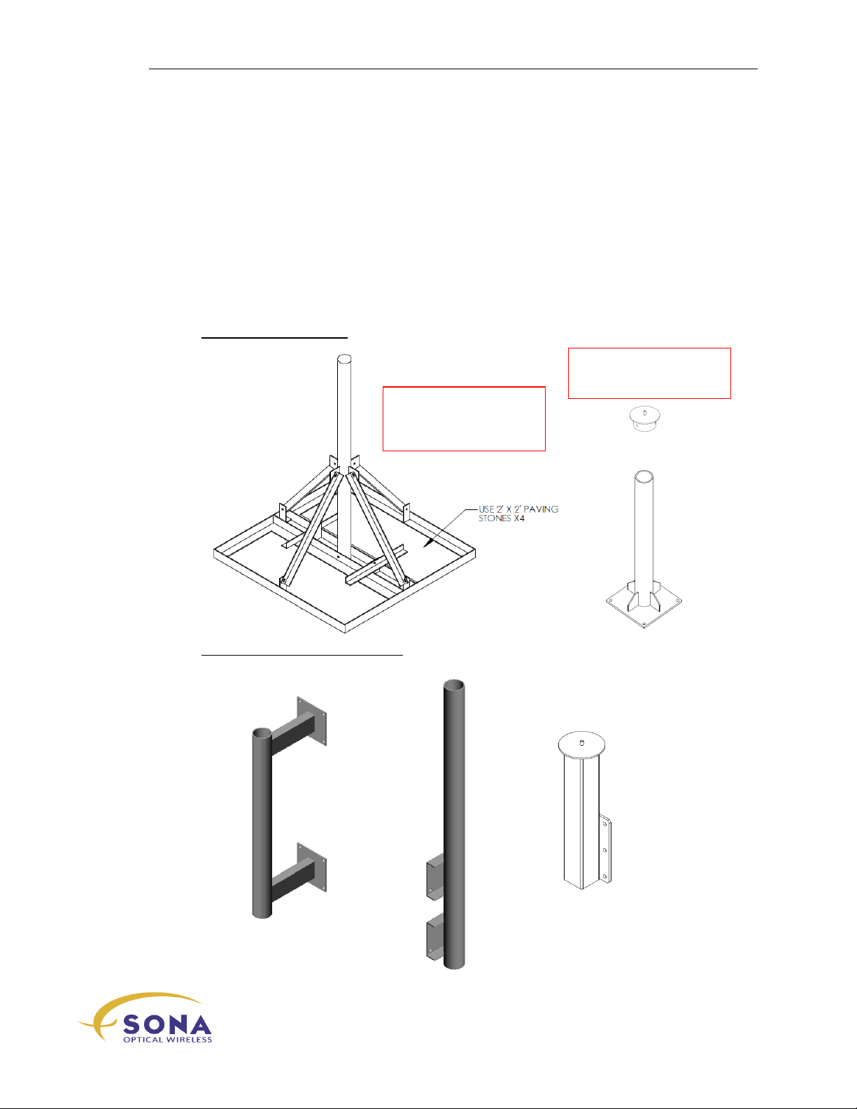
Terminal Mounting Options
In order to achieve a reliable and problem-free FSO link, the importance of a rigid and
stable mount for your SONAbeam terminals cannot be overstated.
The design, fabrication and erection of the mounting mast are all tailored to your specific
installation site(s) and these operations are left to the responsible equipment installers.
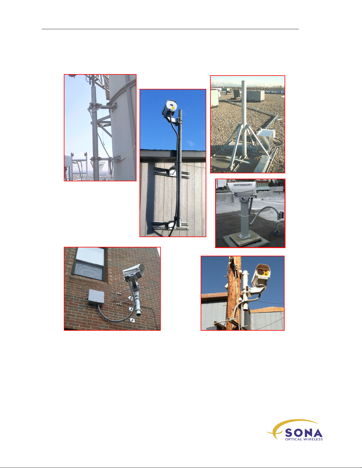
This section illustrates a variety of mounting ideas along with two, ‘off-the-shelf’
mounting options available from fSONA Networks..
ROOF TOP MOUNTING:
into a mount for –E or --Z
fabricated structure ‘sits’ on
PARAPET OR WALL MOUNTING:
Stones, this quickly
wireless at the speed of light …………….
11
-Series Installation Manual
Page 22
Preparing Your Installation Site
For example, some actual mounts:
Figure 3 – Typical SONAbeam Mounting Mast Designs
NAbeam E-Series Installation Manual
12
wireless at the speed of light …………….
Page 23
Preparing Your Installation Site
WARNING!
When constructing your mast in exposed areas outdoors, ensure it has a solid
ground connection. A 6AWG insulated, stranded ground wire, no longer than 25’ in
length is recommended.
NOTE…
Contact your local fSONA representative for assistance in deploying suitable
mounting masts. Refer to specific application notes for tower installations and more
information on rooftop installations. These application notes are available from
your fSONA representative:
APPNOTE-95-0009 Mounting SONAbeams on Buildings
APPNOTE-95-0185 Mounting SONAbeams on Towers
APPNOTE-95-0227 Mounting Stablity for SONAbeams Pt.1
APPNOTE-95-0252 Mounting Stablity for SONAbeams Pt. 2
Fabrication drawings for all of the illustrated mounting options are available by
special request. Contact fSONA networks for more information…
STANDARD OPTIONS FROM fSONA
Pole/Wall Mount
The optional Pole Mount is designed for
mounting a SONAbeam terminal to any
stable, vertical, steel mast with a 2 ½” to 4
½” O.D. (4” O.D. is recommended...) and a
minimum wall thickness of ¼“. The mast
may be rooftop mounted or wall mounted, as
in the examples shown in Figure 3. This
mounting option comes complete with a pair
of U-bolts and associated hardware bits.
This accessory can alternatively be affixed directly to a wall.
wireless at the speed of light …………….
-Series Installation Manual
13
Page 24
Preparing Your Installation Site
Square or rectangular
Minimum platform
Minimum platform
Mounting Stud:
Material:
Clearance for rotation:
Pedestal Mount
The optional Pedestal Mount is designed for
mounting a SONAbeam terminal approximately
600mm (2ft) above any level, hard, flat and stable
surface.
With suitable anchors for the base surface, the bolton Pedestal Mount offers economical rapid
deployment of a versatile terminal platform.
Customer Fabricated Mount
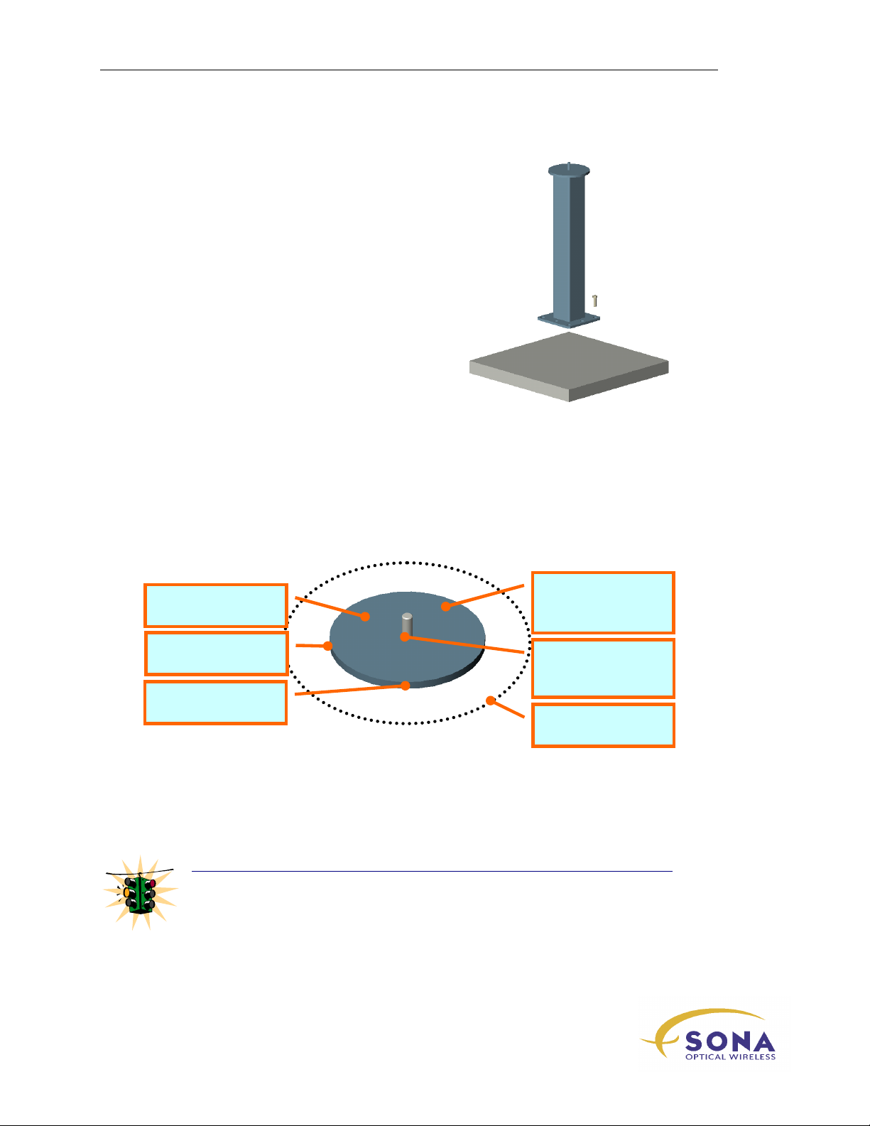
The elegance of the E-Series terminal’s integrated mounting plate makes it possible for
you to easily fabricate your own mounting platform for an E-Series SONAbeam terminal
using the following information:
Steel
w/suitable finish
surfaces are likewise
effective…
surface: 180mm (7”)
thickness: 6mm (1/4”)
½”-13 UNC (or M12)
¾” (
19mm
) above base
225mm (9”)
Mounting surface must be FLAT and relatively level…
Mounting Stud can be alternatively fabricated with M12 thread provided
installer provides matching M12 nut to replace the ½”-13 UNC nut provided
with your terminal.
WARNING!
When constructing your mount on rooftops, ensure it has a solid ground
connection. A 6AWG insulated, stranded ground wire, no longer than 25’ in
length is recommended.
NAbeam E-Series Installation Manual
14
wireless at the speed of light …………….
Page 25
Preparing Your Installation Site
WARNING!
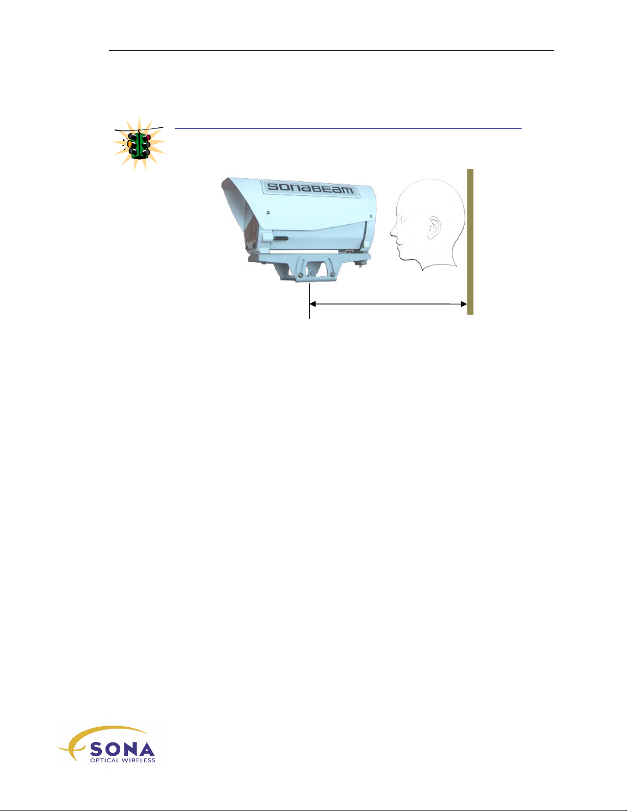
When mounting your terminal on a wall, be sure to allow for space BEHIND the
terminal for installation and alignment, as illustrated here.
wireless at the speed of light …………….
-Series Installation Manual
15
Page 26

Preparing Your Installation Site
SONAbeam Power Requirements
SONAbeam E – Series terminals are factory configured to operate from either 90 –
240VAC or a SELV (Secondary Extra Low Voltage) -48VDC power source. An earthed,
power system is required in which connection to the earthing electrode is located at the
source and separate earthed and protective earthed conductors are provided throughout
the system.
The power requirements of the E Series SONAbeam terminal are:
DC Powered
Input Voltage: -40 VDC to -58 VDC, SELV (@ the terminal, not the source!)
Power: 40 watts max. (Window heater on)
AC Powered
Input Voltage: 100 – 240 VAC (@ the terminal, not the source!)
Power: 40 watts max. (Window heater on)
NOTE…
When powering your terminal from an AC source, the SONAbeam terminal should be
powered from dedicated branch circuit…
The input to the terminal is protected by a user-resettable circuit breaker…
The terminal’s window heater is never activated in temperatures above 25° C…
WARNINGS!
Power cabling to the Customer Interface Box should be no less than 16 AWG – with 14
AWG recommended for cabling runs longer than 100 feet (30 m).
18 AWG is recommended for power cabling from your Customer Interface Box to the
SONAbeam terminal.
Stated voltage requirements are at the terminal’s input power connector strip and NOT
the voltage source!
Always remove power when making connections between the power source and the
Customer Interface Box or SONAbeam terminal!
A two-pole source power disconnect device MUST be implemented when the neutral
wire cannot be identified at the terminal.
NAbeam E-Series Installation Manual
16
wireless at the speed of light …………….
Page 27
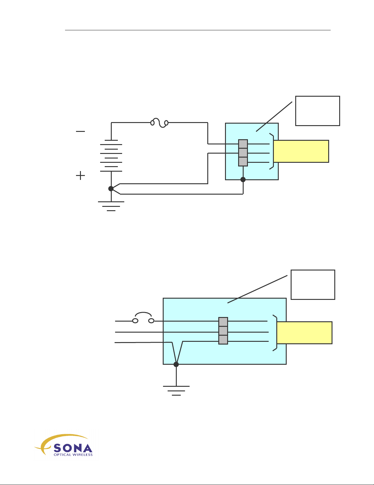
DC Power Source
When using a DC Power Source, it is best to provide a dedicated, overload protected
branch circuit to your Customer Interface Box, as shown in Figure 4.
48 VDC
Preparing Your Installation Site
Customer
Interface
Box
5A
-48 VDC Power
to SONAbeam
Earthed Conductor
Protective Earth Conductor
Earthing Electrode
Figure 4 – Terminal Power from a -48VDC Source
AC Power Source
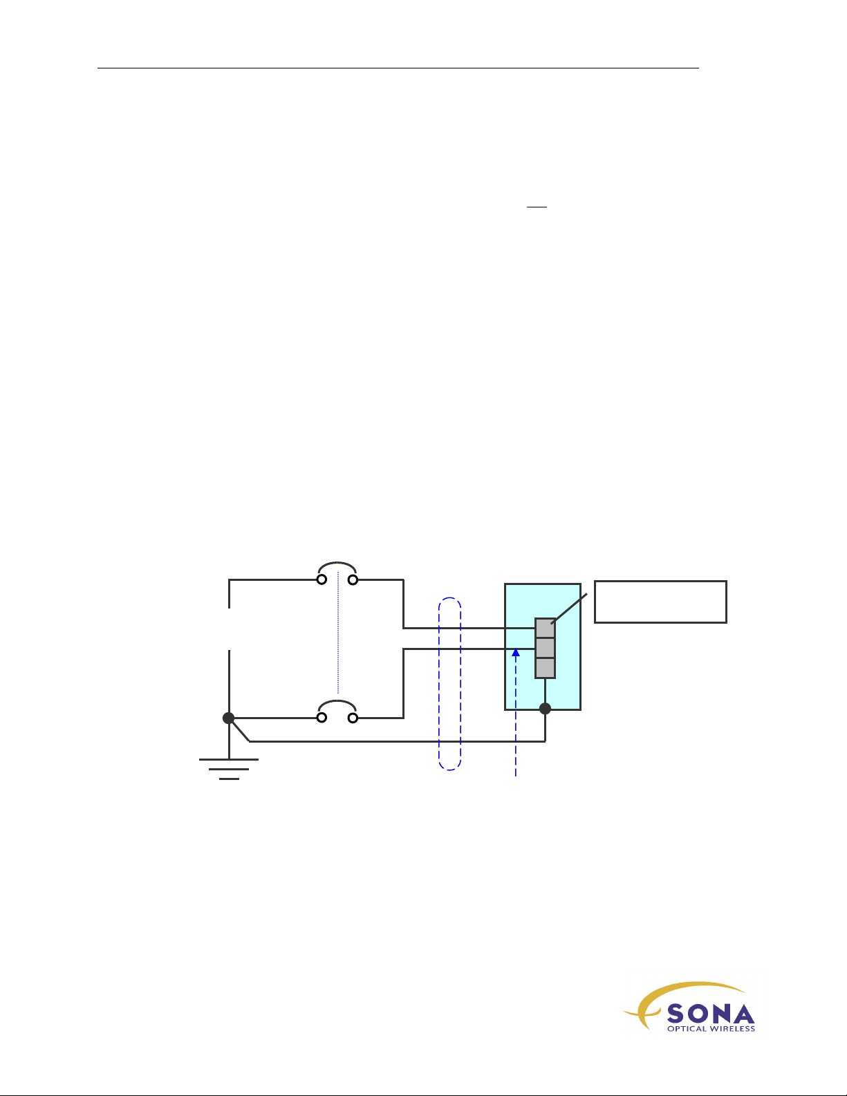
When using an AC Power Source, it is best to provide a dedicated, overload protected
branch circuit to your Customer Interface Box, as illustrated in Figure 5, to power your
SONAbeam terminal.
L
AC
Mains
N
AC Power to
SONAbeam
Customer
Interface
Box
Figure 5 - Terminal Power from a 100-240VAC Source
wireless at the speed of light …………….
17
-Series Installation Manual
Page 28
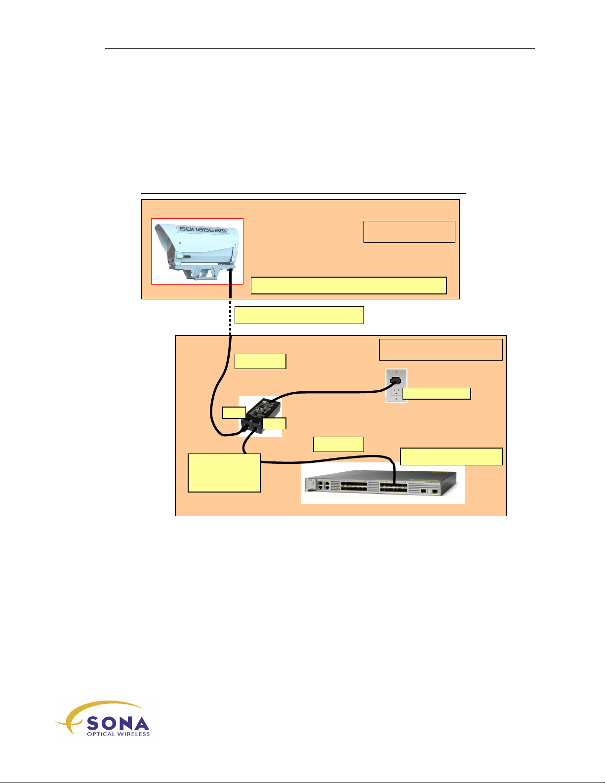
Preparing Your Installation Site
Terminal Power
Suitable power
Protective Earth Conductor
Earthed
Conductor
Terminal Power
Source
Line Conductor
* A two
-
pole (simultaneous) disconnect device is required when
Installed
SONAbeam Safety Certification
To retain the safety certifications of your SONAbeam terminals, the power system
installed for your terminals must provide short circuit protection and a suitable power
disconnect device:
Circuit Protection
A fuse or circuit breaker suitable for branch circuit protection MUST be provided in the
building installation.
A single pole protection device is acceptable where the earthed conductor in the Mains
Supply can be positively identified (where it connects to the equipment). In this case, the
protective device need only interrupt the unearthed (line) conductor.
However, when the equipment is used where the identification of the earthed conductor
in the Mains Supply is not possible, the protective device must interrupt both supply
conductors simultaneously.
Power Disconnect Device
Power disconnect protection MUST be provided in the building installation to allow
isolation of the equipment from its power source.
When the equipment is used where the identification of the earthed conductor in the
Mains Supply is not possible, a two-pole breaker (or similarly functioning simultaneous
two-pole disconnect device) must be employed.
disconnect device
wiring
Connector
*
Earthing
Electrode
identification of the Earthed Conductor is not possible here…
NAbeam E-Series Installation Manual
18
wireless at the speed of light …………….
Page 29
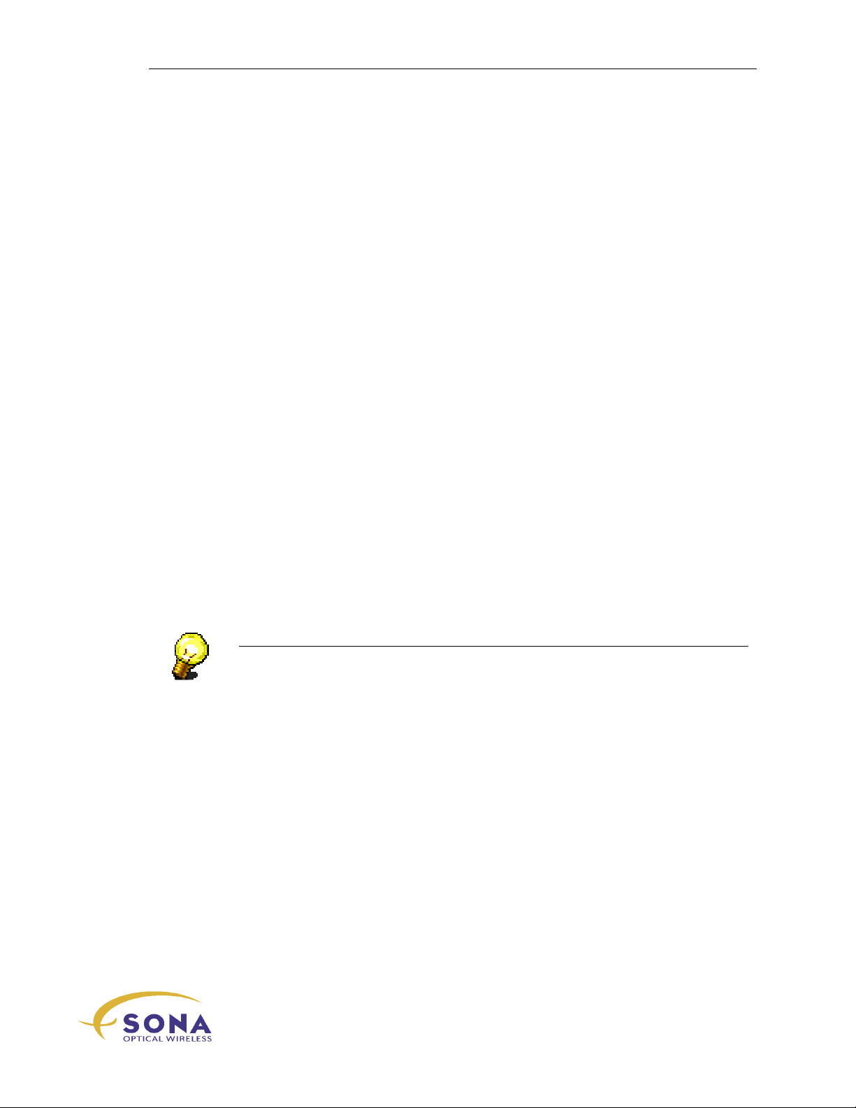
Preparing Your Installation Site
SERVER ROOM
ROOF TOP
90 –
250 VAC
Power Over Ethernet
When your terminal is DC powered, you may optionally employ Power Over Ethernet
(POE) to power your terminals. The POE option allows you to run a single CAT 6 cable
from your server room to your SONAbeam terminal to provide BOTH terminal power
and Ethernet terminal management.
SYSTEM DIAGRAM
DC Powered SONAbeam Terminal
100m / 300 ft. MAX.*
CAT 5*
OUT
IN
CAT 5
Network Switch
POE Power
Injector
* POE Injector to Terminal CAT5 requirements:
<100m 22/24 AWG
<50m 26 AWG
wireless at the speed of light …………….
19
-Series Installation Manual
Page 30

Preparing Your Installation Site
SONAbeam Fiber Requirements
Your SONAbeam E-Series terminal employs an industry standard small form-factor
pluggable (SFP) transceiver for network traffic. The following Interface options are
available from the factory:
FIBER:
10-0056A (155-E & 1250-E)
Description: 1000-Base-LX, Single mode fiber, LC terminated, 1310nm
TX output power: -9 dBm (min) -3 dBm (max)
RX input power: -21 dBm (min) -3 dBm (max)
10-0057A (155-E & 1250-E)
Description: 1000-Base-SX, Multimode fiber, LC terminated, 850nm
TX output power: -9 dBm (min) -3 dBm (max)
RX input power: -17 dBm (min) 0 dBm (max)
10-0084A (2500-E)
Description: 2.5 Gbps SFP, Single mode fiber, LC terminated, 1310nm
TX output power: -5 dBm (min) 0 dBm (max)
RX input power: -18 dBm (min) -3 dBm (max)
10-0085A (2500-E)
Description: 2.5 Gbps SFP, Multimode fiber, LC terminated, 850nm
TX output power: -10 dBm (min) -3 dBm (max)
RX input power: -18 dBm (min) -3 dBm (max)
COPPER:
10-0058A (1250-E)
Description: 1000-BaseT, RJ45 terminated, copper
10-0082A (155-E)
Description: 100-BaseT, RJ45 terminated, copper
WARNING!
When providing your own SFP transceiver, verify its product compatibility with
fSONA Networks.
NAbeam E-Series Installation Manual
20
wireless at the speed of light …………….
Page 31
Preparing Your Installation Site
Customer Interface Box
Your Customer Interface Box is intended to provide installable connectivity between
your SONAbeam terminal and your network, power and terminal management interfaces.
For rooftop installations, while arguably convenient, in some special cases you may
choose to omit this intermediary junction box and run your terminal interfaces – through
a suitable conduit – from your terminal directly to your cabling closet – through an
appropriate penetration point – where connections to your network, power source and
management computer(s) are made.
When the Customer Interface Box is included in your installation plans, provide an
enclosure that will accommodate your entire interface needs and as well as meet the
demands of its surrounding environment. When installed outdoors, your Customer
Interface Box should meet the requirements of NEMA 3, or equivalent.
Additional Considerations
When preparing for your SONAbeam installation, consider all of the supporting
networking requirements. This may include:
Computers that will host SONAbeam Terminal Controller (STC) software for
monitoring link performance and managing configuration changes…
CAT 5/CAT-6 serial and/or LAN connection(s) to the SONAbeam terminals for
monitoring and managing your SONAbeam link(s)…
NOTE…
While the typical SONAbeam installation includes a CAT 5 cable interface to manage
the terminal through a LAN connection, a secondary CAT 5 cable interface to the
terminal’s Serial Console Port can pay enormous dividends as a backup connection.
The ‘insurance’ provided by a secondary, serial connection to your terminal is
especially prudent when the SONAbeam is mounted in a less-than-accessible location!
At the very least, a secondary, serial interface from your SONAbeam to your Customer
Interface Box will provide access to complete diagnostic capabilities from that location.
SM or MM fiber (dependent on the interface option selected for your E-Series
terminal) optic network interfaces to your Customer Interface Boxes, with
appropriate patch cords, media converters and/or switches/routers and/or
attenuators and/or other fiber modules…
wireless at the speed of light …………….
21
-Series Installation Manual
Page 32

Preparing Your Installation Site
NOTE…
While your SONAbeam terminal can be ordered with an interface for either singlemode or multi-mode fiber optic cables, but note that there are fiber transmit and receive
power limitations for proper network performance. (See the latest SONAbeam E-Series
fiber interface specification datasheets for more information)…
Matching the fiber requirements – fibre type, wavelength and power – of the
SONAbeam terminals with those of all associated connecting equipment.
If you are also implementing a redundant RF link or wire line path, you must also
consider the necessary switch/router programming to steer your data through the
appropriate link.
NAbeam E-Series Installation Manual
22
wireless at the speed of light …………….
Page 33
Unpacking Your SONAbeam Terminal
Unpacking Your
SONAbeam Terminal
While unpacking your SONAbeam terminals from their shipping boxes, an inventory
should be taken to ensure that all of the necessary components are included for your
installation.
This section provides information on the component parts that comprise each terminal.
WARNING!
SONAbeam terminals are precision optical devices and therefore
require careful handling…
Do NOT remove the SONAbeam terminals from their shipping cartons
until you are ready to install them…
The Product Package
Each SONAbeam E-Series terminal, and its associated mounting accessories, is described
in this section…
WARNING!
Confirm a complete inventory before commencing your installation!
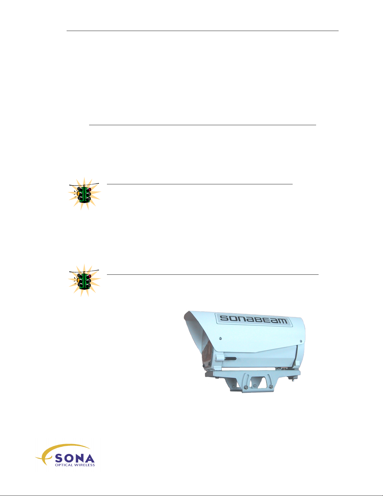
SONAbeam Optical Head &
Mounting Plate Assembly
-Series Installation Manual
wireless at the speed of light …………….
23
Page 34
Unpacking Your SONAbeam Terminal
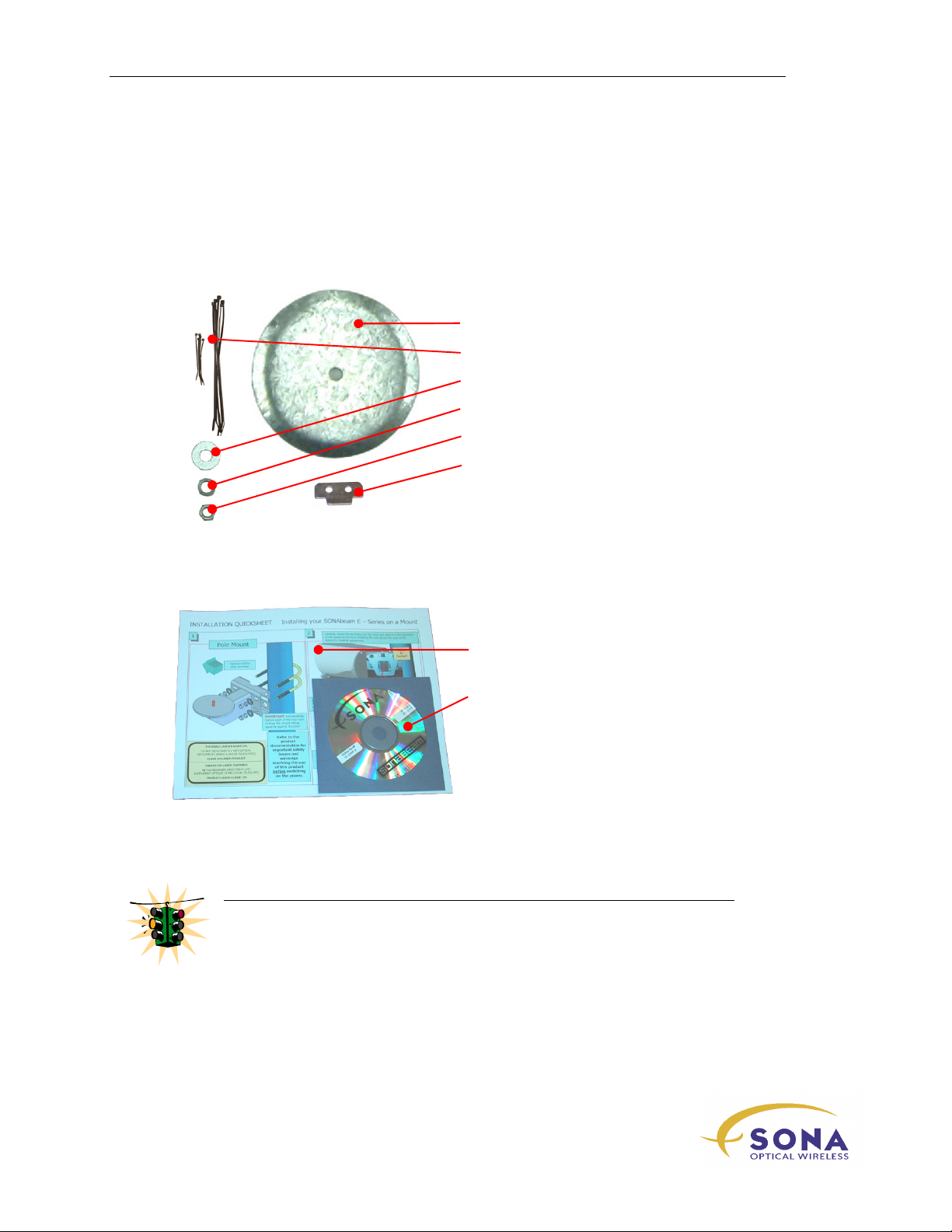
SONAbeam E-Series Installation Kit
The E-Series Installation Kit includes the following items:
Mounting hardware:
1 – Azimuth locking plate
10 – Cable ties (5 short & 5 long)
1 – ½” flat washer
1 – ½” lock washers
1 – ½” hex nut
1 – Cable strain relief
Documentation:
WARNING!
If any of these items are missing or damaged, immediately notify your fSONA
representative!
Confirm a complete inventory before commencing your installation!
1 – SONAbeam E-Series Installation
QUICKSHEET
1 – SONAbeam Utilities Software CD
NAbeam E-Series Installation Manual
24
wireless at the speed of light …………….
Page 35
Unpacking Your SONAbeam Terminal
fSONA PN: 80
-
0030A
Optional Accessories
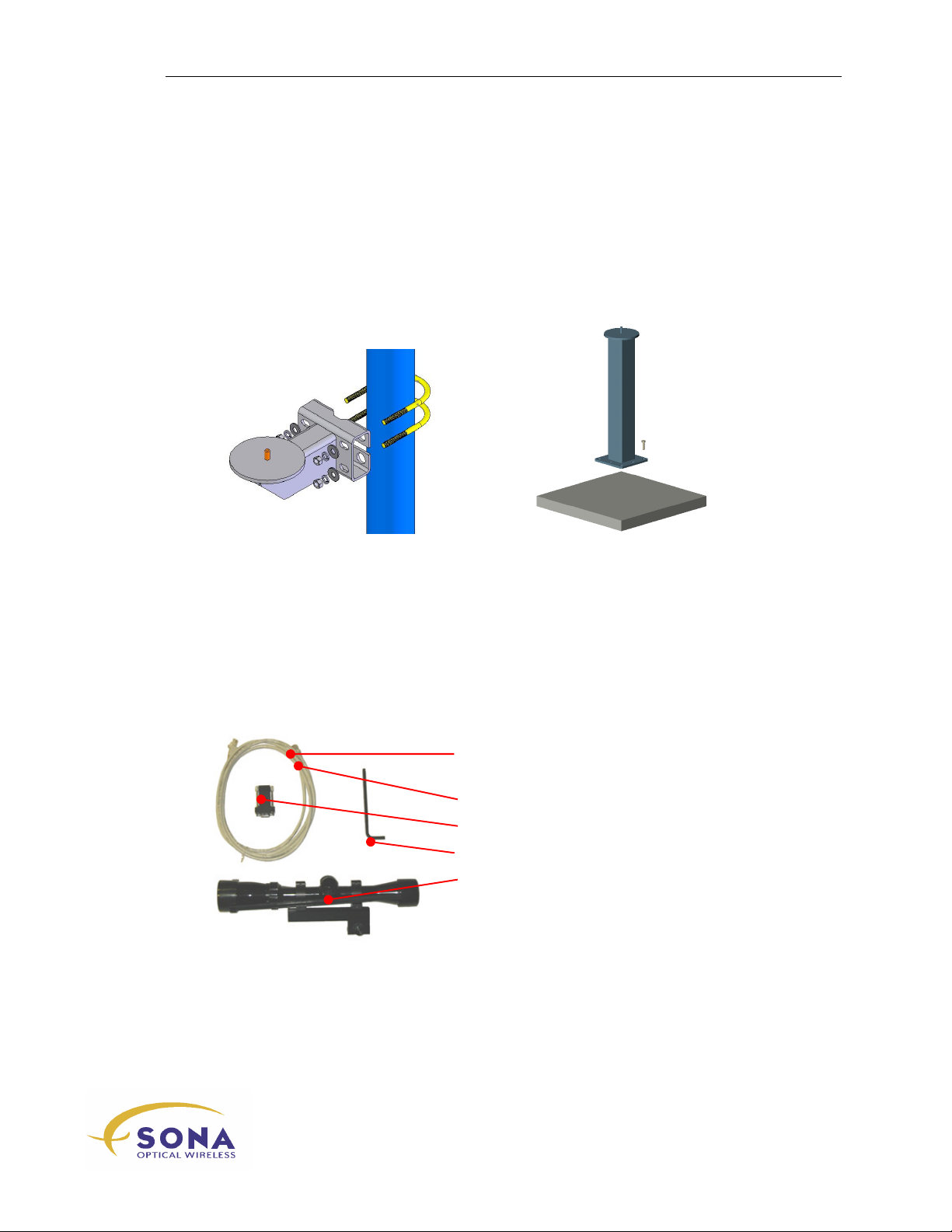
The following optional accessories are available from fSONA to help with the success of your
FSO installation:
(OPTIONAL) Terminal Mounts
The Pole/Wall Mount and the Pedestal Mount both provide a ready-made platform on which to
mount and align your SONAbeam terminals.
fSONA PN: 80-0031A
(OPTIONAL) Basic Alignment Kit
The Basic Alignment Kit – fSONA Part No. 80-0047A – provides the accessories needed to
perform the alignment of a newly installed SONAbeam terminal. Typically, you will require
two kits to perform your link alignment, one kit for each terminal.
1 – 3m CAT 5 communication cable w/ RJ45
ends
1 – 3m USB cable Type A/B
1 – DB9 – RJ45 cable adapter
1 – 5mm Allen wrench
1 – 9X Alignment scope w/ mount
(NOTE: The Alignment Scope includes a
special spectral filter that allow you to safely
‘look at’ the opposing terminal’s laser beam.)
wireless at the speed of light …………….
-Series Installation Manual
25
Page 36
Unpacking Your SONAbeam Terminal
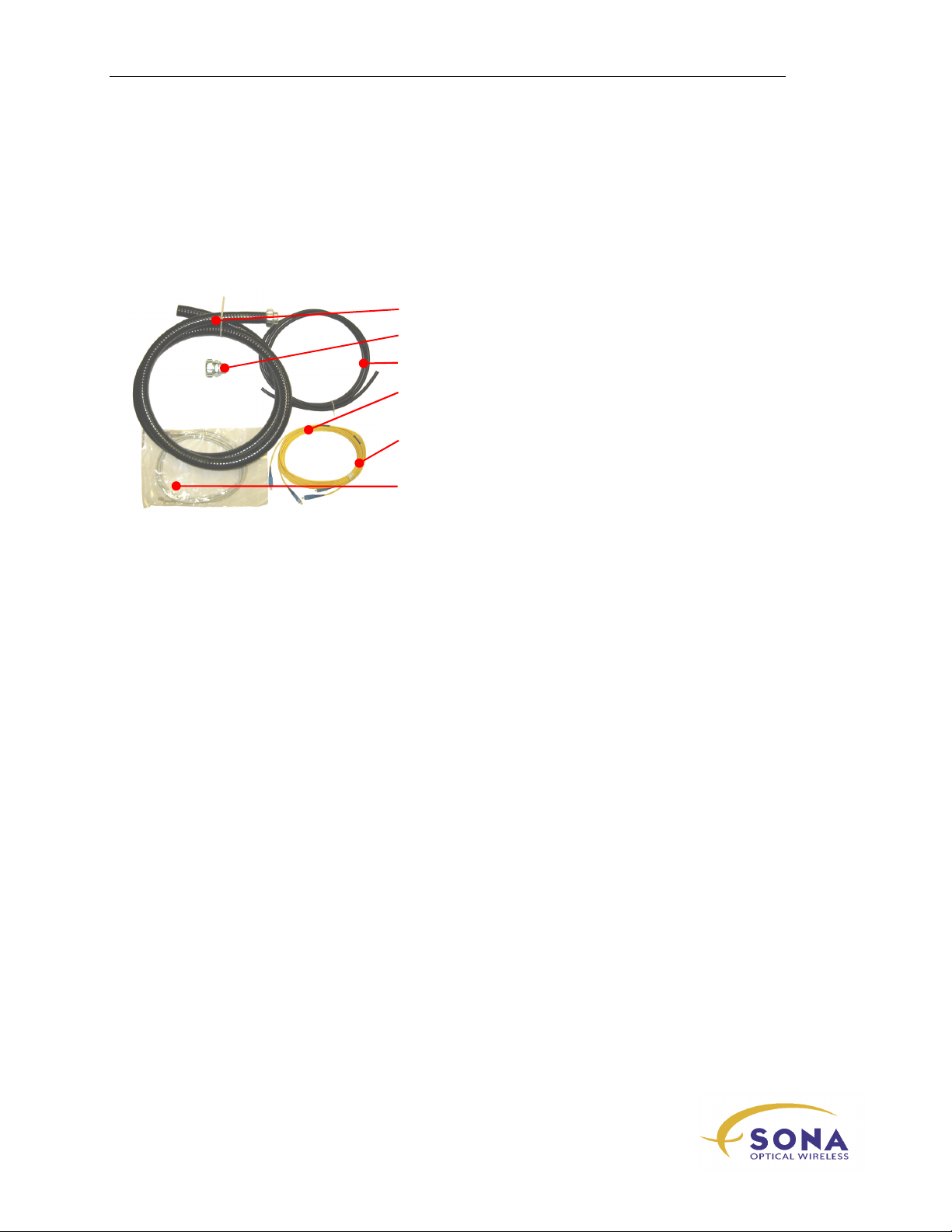
(OPTIONAL) Customer Interface Kit
The Customer Interface Kit – fSONA Part No. 80-0168A – provides the material required to
interface your terminal’s power and communications to your (suitably located, installer
provided) Customer Interface Box:
1 – 2.25m 1” Liquid-Tight flexible conduit
1 – 1” Liquid-Tight conduit connector kit
1 – 3m 3-18 AWG power cable
1 – 3m Single-mode DUPLEX fiber optic cable
w/ LC ends
1 – 3m Multi-mode DUPLEX fiber optic cable
w/ LC ends
2 – 3m CAT 5 communication cables w/ RJ45
ends (serial & LAN)
NAbeam E-Series Installation Manual
26
wireless at the speed of light …………….
Page 37
Unpacking Your SONAbeam Terminal
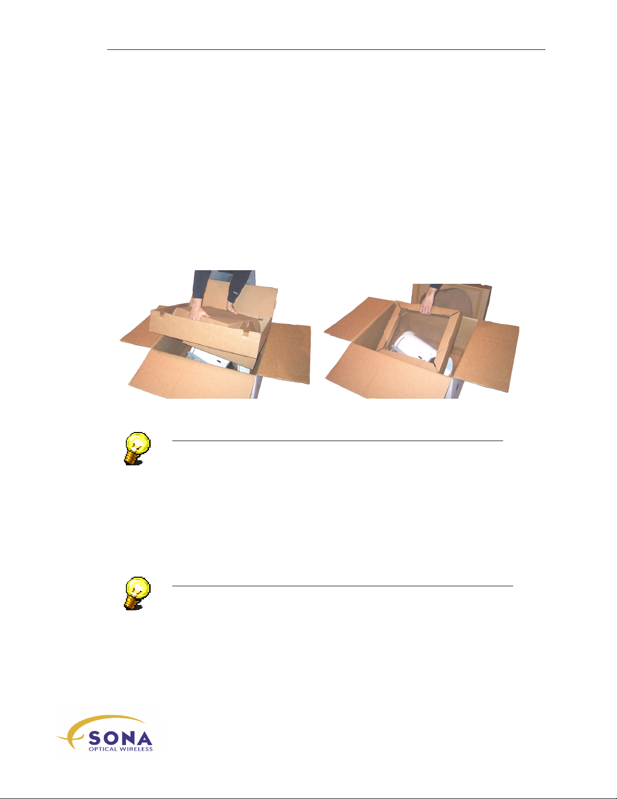
Unpacking the Optical Head
The optical head is shipped in a special, three-piece, protective box system. To unpack
the optical head:
1.
Place the box, top face up, on a stable surface…
2.
Open the box from the top and carefully pull out the upper retainer, as shown in
Figure 6…
3.
Pull out the supplementary retainer, as shown in Figure 6…
4.
Grasp the optical head firmly (preferably by its mounting plate) and carefully lift
it out of its box…
Figure 6 - Unpacking the Optical Head
NOTE…
The optical head is best left in its shipping box until you are ready to install
it…
Unpacking your Installation Kit
Your SONAbeam Installation Kit is packaged in compartmented plastic wrap. To avoid
losing items, you are advised to only break open the compartments containing the items
you need, when you need them…
NOTE…
All boxes used to ship SONAbeam products are 100% recyclable!
-Series Installation Manual
wireless at the speed of light …………….
27
Page 38

Unpacking Your SONAbeam Terminal
NAbeam E-Series Installation Manual
28
wireless at the speed of light …………….
Page 39
Installing Your SONAbeam Terminal
Installing Your
SONAbeam Terminal
The physical installation of SONAbeam terminals is a simple and straightforward
procedure when conducted by qualified personnel in accordance with the procedures
described in this manual.
This section provides the following step-by-step procedures:
Installing the Mounting Assembly…
Installing the optical head Assembly…
Interfacing the optical head and your Customer Interface Box…
WARNING!
The installation and wiring of SONAbeam terminals must be performed by
qualified equipment installers…
Safety First, Safety Always
The installation of the SONAbeam terminal can expose personnel to potential trip
hazards, fall hazards and lifting hazards. TAKE EVERY PRECAUTION TO ENSURE
THE SAFETY OF EVERYONE INVOLVED IN YOUR INSTALLATION EFFORTS!
Before You Begin…
Before you begin to install a SONAbeam terminal, your installation plan should have the
following items completed at BOTH installation sites:
A properly installed and grounded Mounting Mast...
All necessary power and network interfaces run to the installation site and
properly terminated in your Customer Interface Box…
WARNING!
All cabling to the Customer Interface Box must be run in suitably rated conduit…
wireless at the speed of light …………….
-Series Installation Manual
29
Page 40
Installing Your SONAbeam Terminal
Required Tools and Accessories
In order to install your SONAbeam terminals, your toolbox should include the following:
3/4” (or 19mm) wrench – to affix the SONAbeam to its mount…
5mm Allen wrench (included in the optional Basic Alignment Kit) – to secure
the terminal to its mounting assembly, to remove/replace the cover to the
Customer Interface Area and to make alignment adjustments…
‘Stubby’ Philips-head screwdriver – to remove/replace the power connector
cover and to connect source power wiring to the terminal’s power terminals…
Large adjustable wrench – to affix conduit ends…
Needle nose pliers, wire cutters & wire strippers – for power wiring…
Electrical tape and Wire Wraps are also recommended…
NOTE…
Other tools and accessories may be required depending on the equipment boxes
you have installed for your power, monitoring and network interface
connections…
Installing the (Optional) Pole Mount
The optional Pole Mount provides a stable, all-weather, mast-mounted platform for the
SONAbeam E-Series terminal.
NOTE…
See the earlier section: SONAbeam Mounting Masts for more information on
providing an suitable mast on which to mount your SONAbeam terminal…
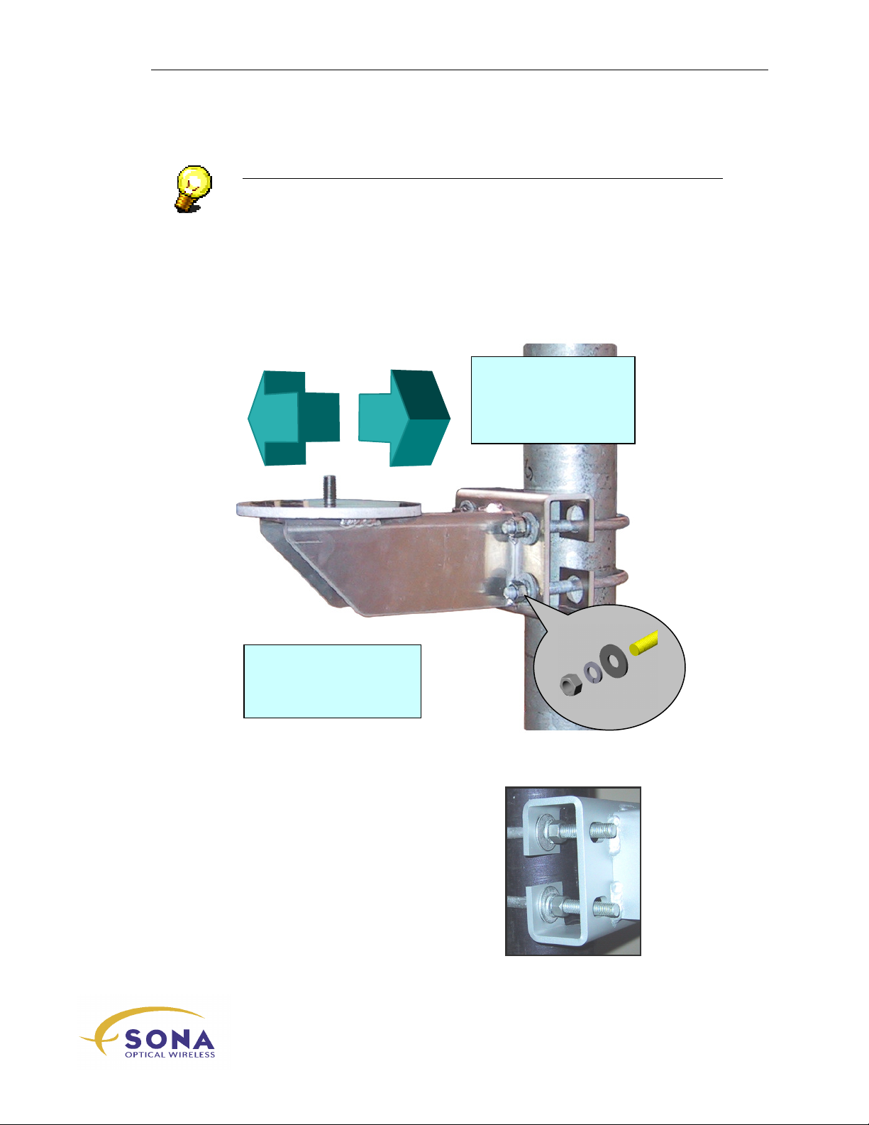
To install the Pole Mount:
1.
Obtain the Pole Mount, the two U-Bolts, and four ½ “flat washers, four ½ “lock
washers and four ½”-13 UNC nuts from the Installation Kit…
2.
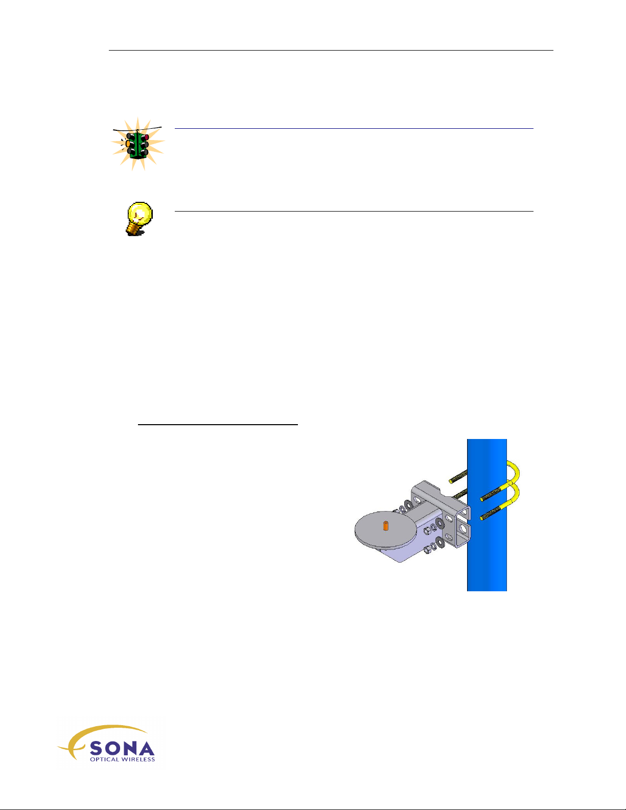
Place the mount against the mast so that it ‘points’ perpendicular to the
approximate line-of-site direction to the other terminal in the link, as shown in
Figure 7.
3.
Using the two U-bolts and associated hardware, secure the mount to the mast so
that it sits squarely against the mast and is sufficiently tight to hold the mount in
place…
NAbeam E-Series Installation Manual
30
wireless at the speed of light …………….
Page 41
Installing Your SONAbeam Terminal
NOTE…
If the mount is to be located near the top of your mast and no obstruction(s) offer
resistance, you might consider loosely assembling the U-bolts and associated
hardware to the mount and then handling that assembly over the top of the mast
sliding the mount down the mast to its prescribed location…
4.
With the mount ‘pointed’ in the proper direction and using a ¾” wrench,
sequentially TIGHTEN all four nuts, being sure to balance your tightening so that
the mount sits squarely against the mast …
NOTE: With suitable
anchors and hardware, this
–E terminal mount can also
be affixed to a wall…
The general direction
of the other
SONAbeam terminal in
your link…
Figure 7- Installing the Pole Mount
NOTE: When affixing your Pole Mount to a
4½“ O.D. post, you may find the u-bolts too
short to accept all of the fastening hardware.
In such cases, you can place the fastening
hardware INSIDE the mounting flange as
illustrated to the right:
Figure 8- Alternate Pole Mount
Installation
wireless at the speed of light …………….
-Series Installation Manual
31
Page 42
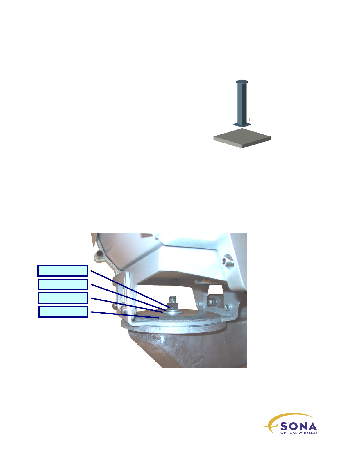
Installing Your SONAbeam Terminal
½“ –
13 UNC nut
½“ lock washer
½“ flat washer
Locking Plate
Installing the (Optional) Pedestal Mount
The optional Pedestal Mount provides a stable, allweather, surface-mounted platform for the SONAbeam ESeries terminal. With suitable installer-provided anchors
installed in your base surface, the Pedestal Mount bolts in
place for rapid FSO deployment.
Installing the Optical Head
The optical head for SONAbeam E-Series terminals is pre–assembled with a
mounting/alignment plate, which easily affixes to the installed mount.
To install the Optical Head:
1.
Obtain the Locking Plate, and one ½ “flat washer, one ½ “lock washer and one
½”-13 UNC nut from the Installation Kit…
2.
Carefully lift the optical head BY ITS MOUNTING PLATE and place it on the
mount, inserting the mount’s threaded stud through the hole in the centre of the
mounting plate…
Figure 9 – Mounting the Optical Head
NAbeam E-Series Installation Manual
32
wireless at the speed of light …………….
Page 43
Installing Your SONAbeam Terminal
3.
Place the Locking Plate, the ½ “flat washer, the ½ “lock washer and the ½”-13
UNC nut onto the mounting plate, as shown in Figure 9…
NOTE…
The Locking Plate must be oriented concave-side DOWN…
4.
Tighten the nut just to the point where the mounting plate not longer swivels on
the Mount and then back off to the point where the mounting plate will swivel.
Customer Interface Connections
With the mounting of the SONAbeam optical head completed, you may proceed to make
the necessary customer interfaces to your Customer Interface Box.
Your Customer Interface Box will need to provide appropriate cable feeds and
terminations – for the electrical, the link network (SM or MM fiber) and Ethernet and/or
serial interface(s) (CAT5 UTP) for SONAbeam management – necessary to deploy your
FSO link. In most cases, the installation of these services will result in the provisioning of
termination/coupling points inside the Customer Interface Box; although the ability to
directly connect the services to the SONAbeam terminal is also an option.
NOTE…
While the typical SONAbeam installation includes a CAT 5/6 cable interface to manage
the terminal through a LAN connection, a secondary CAT 5 cable interface to your
terminals’ Serial Console Ports can pay enormous dividends as a backup connection.
The ‘insurance’ provided by a secondary, serial connection to your terminal is
especially prudent when the SONAbeam is mounted in difficult to reach locations!
At the very least, a secondary, serial interface from your SONAbeam to your Customer
Interface Box will provide access to complete diagnostic capabilities from that location.
Building your interface between the SONAbeam terminal and your Customer Interface
Box comprises the following operations:
Sizing the Liquid-Tight conduit needed between the terminal and the Customer
Interface Box and preparing both unfinished conduit ends…
Threading your power, your serial and/or Ethernet, and your fiber optic cabling
through the finished conduit…
Attaching the ends of the finished conduit to the terminal and the Customer
Interface Box and terminating/connecting all of the interface cables…
This section details these operations.
-Series Installation Manual
wireless at the speed of light …………….
33
Page 44
Installing Your SONAbeam Terminal
Optional Customer Cabling Kit
An optional E-Series Cabling Kit is available from fSONA, which provides all of the
components necessary to interface a SONAbeam to a suitably located Customer Interface
Box. This optional kit includes:
ONE – 2.3m length of 1” Liquid-Tight flexible conduit, with 1” conduit
connector kit…
ONE – 3m length of 3-18 AWG power cable…
TWO – 3m CAT5 patch cable with RJ45 terminated ends…
TWO – 3m multimode duplex fiber optic cable with LC terminated ends…
TWO – 3m single mode duplex fiber optic cable with LC terminated ends…
WARNING!
If you choose to provide your own interface components, the conduit must
provide a watertight interface to the terminal.
For powering your SONAbeam terminals, use standard, compliant power
cordage that meets or exceeds the following:
18 – 14 AWG stranded; 300 Volts; -40°C to 85°C
In extreme environments, select suitably rated power cordage!
Furthermore, all applicable local/regional safety codes MUST be observed!
SONAbeam Customer Interface Area
All of the customer-provided interfaces are made in the SONAbeam terminal’s Customer
Interface Area inside the optical head through the customer-provided, 1” flexible LiquidTight conduit.
To remove the cover to the Customer Interface Area:
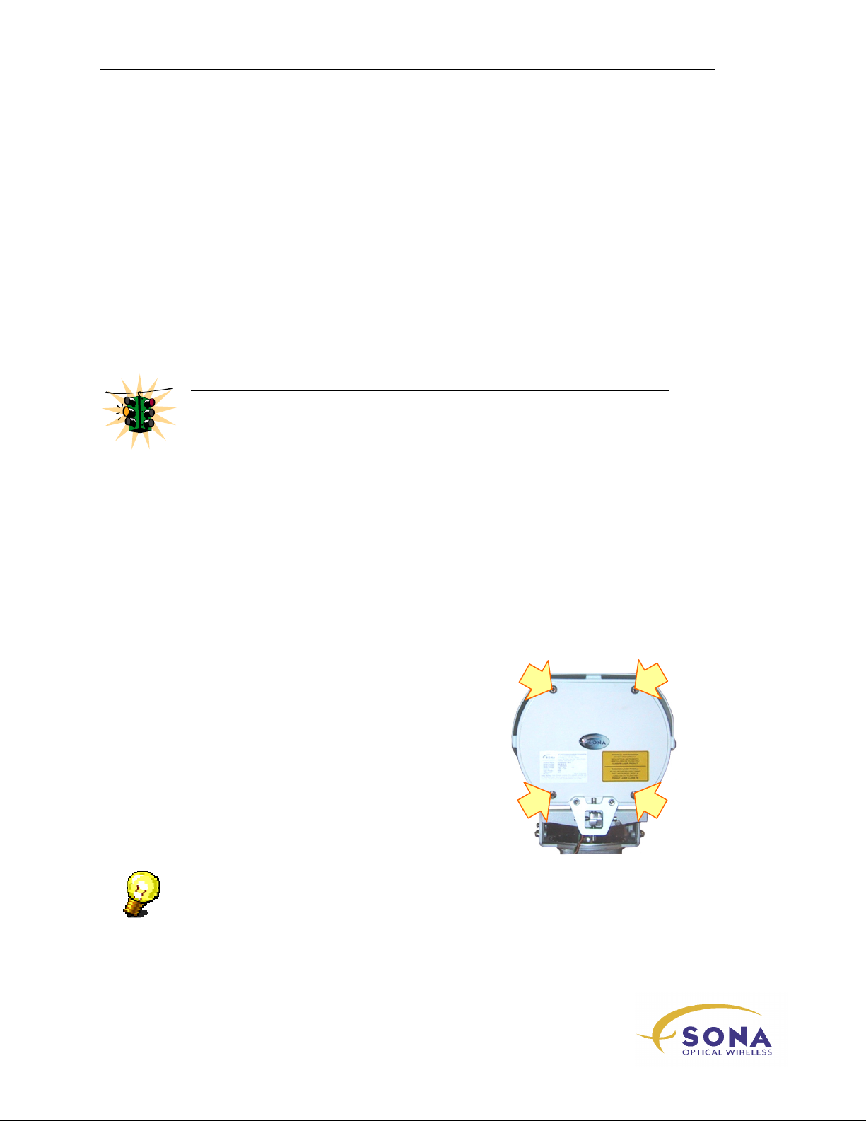
1.
Using a 5mm Allen wrench – one is provided in
the optional Basic Alignment Kit – loosen the
four cover screws shown in Figure 10…
Figure 10 – SONAbeam Customer
Interface Cover Screws
NOTE…
The four Customer Interface Cover screws are captive and the cover itself is
tethered to the optical head…
NAbeam E-Series Installation Manual
34
wireless at the speed of light …………….
Page 45
Installing Your SONAbeam Terminal
2.
Carefully remove the cover and let it hang from the optical head on the attached
tether cable.
WARNING!
The SONAbeam Customer Interface Compartment includes a special gasket for
weatherproofing and EMI control. DO NOT damage this gasket!
While the installer provides the 1” interface conduit – Electroflex EMSP-13, or
equivalent, is recommended – the conduit hardware to provide a mating interface to the
terminal’s conduit entrance is included in the terminal’s Installation Kit.
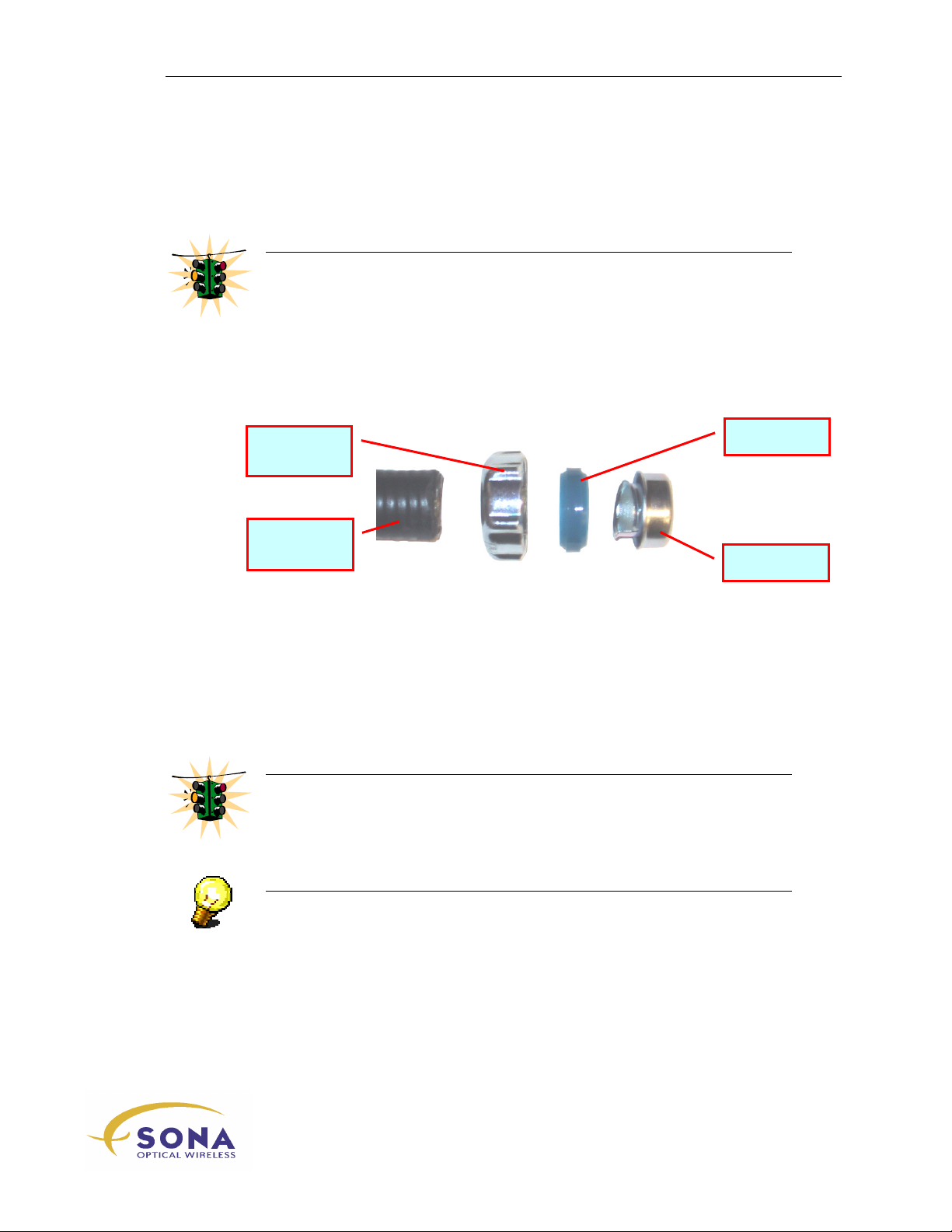
Retaining
Nut
Liquid-Tight
Conduit
To affix the Customer Conduit:
1.
WARNING!
Be sure to provide sufficient slack to allow movement of the optical head for
alignment!
NOTE…
Temporarily route your Liquid-Tight flexible conduit from your Customer
Interface Box to the conduit entrance on the optical head in order to ascertain the
appropriate length to join the two…
Nylon Seal
Ferrule
The age-old adage: “Measure twice, cut once…” is very appropriate for this
operation…
2.
Mark and cut the conduit end, using a fine-tooth hacksaw or other appropriate
tool…
-Series Installation Manual
wireless at the speed of light …………….
35
Page 46
Installing Your SONAbeam Terminal
3.
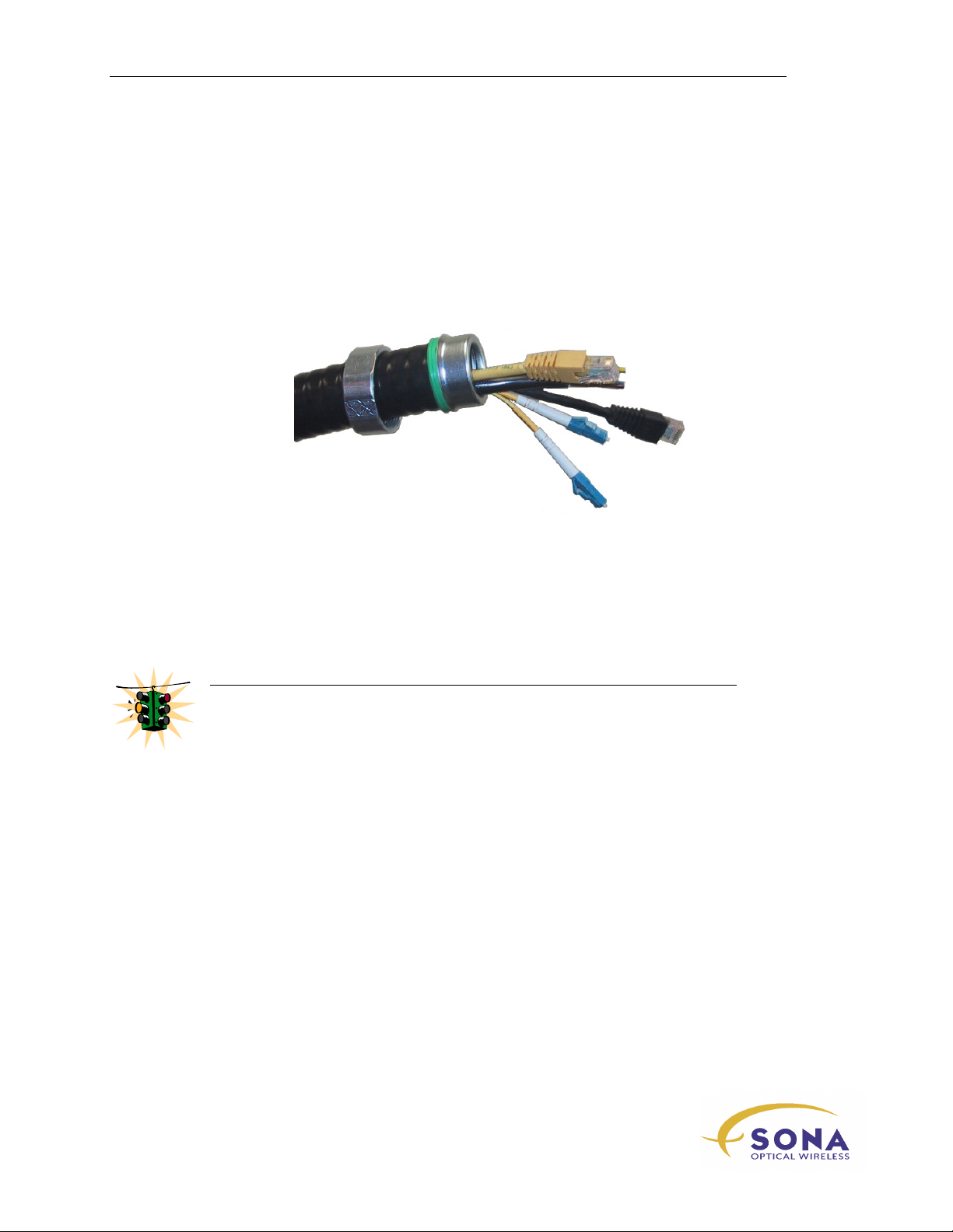
Slip the retaining nut and nylon seal over the end of the conduit and carefully
and firmly screw the ferrule into the conduit end until it is fully seated, as shown
in Figure 11…
4.
Carefully route the required fiber optic, power and management cable(s) through
the Interface Conduit.
5.
Carefully thread the fiber optic, power and management cable(s) through the
terminal’s conduit entrance at the bottom of the optical head and engage the end
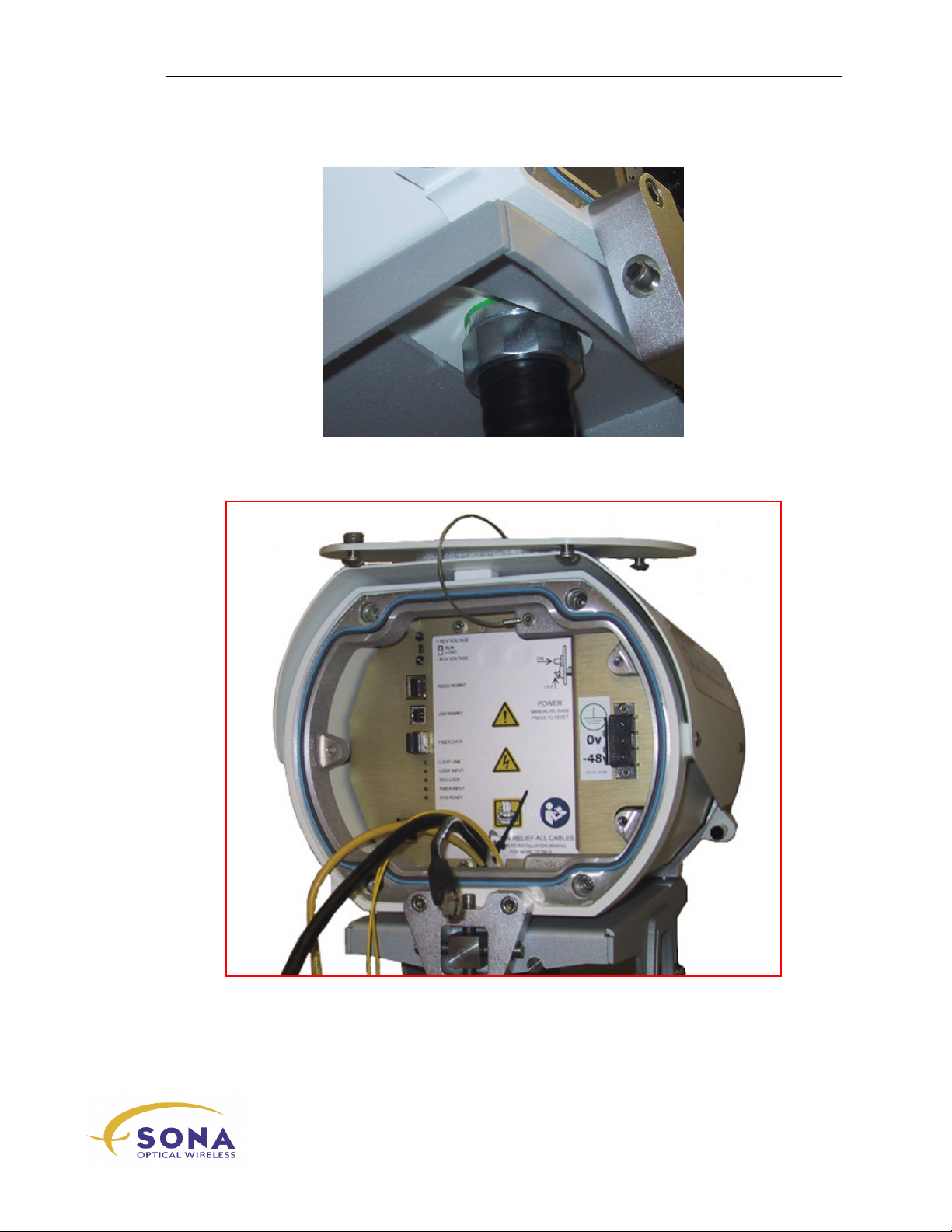
of the conduit into the conduit fitting, as shown in Figure 12…
6.
Slip the retaining nut up to the end of the conduit and carefully tighten it by
hand while holding the conduit vertically aligned…
WARNING!
Be careful not to cross thread the retaining nut!
Hand-tight is NOT sufficient!
7.
Using an appropriate wrench, tighten the retaining nut sufficiently to slightly
compress the nylon seal…
Figure 11 – Conduit End ready for Installation
NAbeam E-Series Installation Manual
36
wireless at the speed of light …………….
Page 47
Installing Your SONAbeam Terminal
Your installation should now resemble that illustrated in Figure 12.
Figure 12 – The Attached Interface Conduit
wireless at the speed of light …………….
-Series Installation Manual
37
Page 48
Installing Your SONAbeam Terminal
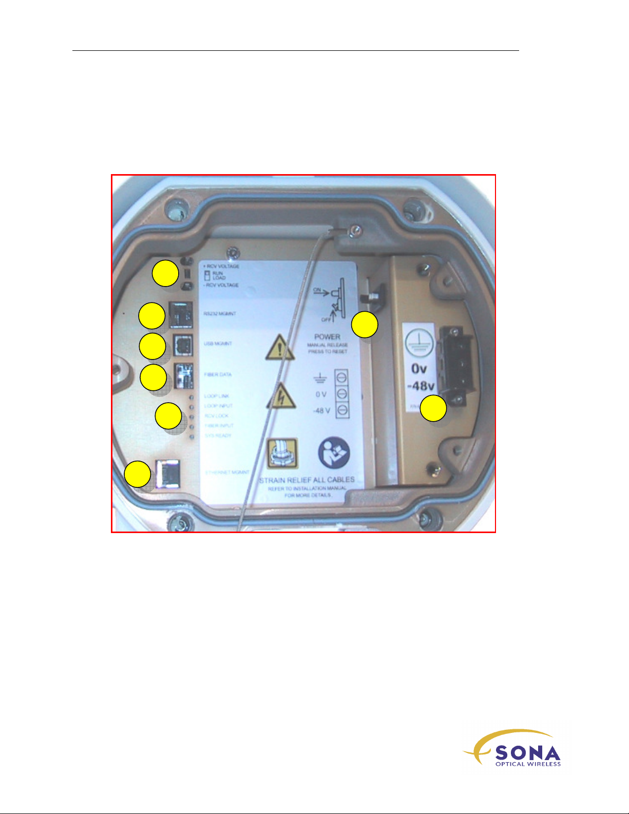
E-Series Customer Interfaces
Your SONAbeam E-Series terminal provides the following customer interfaces:
1
2
3
4
5
6
1
DVM terminals for alignment
2
Terminal Management port – RS232
7
8
5
Terminal Status LEDs
6
Terminal Management port –
Ethernet
7
3
Terminal Management port – USB
4
Network Traffic SFP
NAbeam E-Series Installation Manual
38
wireless at the speed of light …………….
Terminal Power Circuit
Breaker/Switch
8
Terminal Power Input
Page 49
Installing Your SONAbeam Terminal
Power Connections
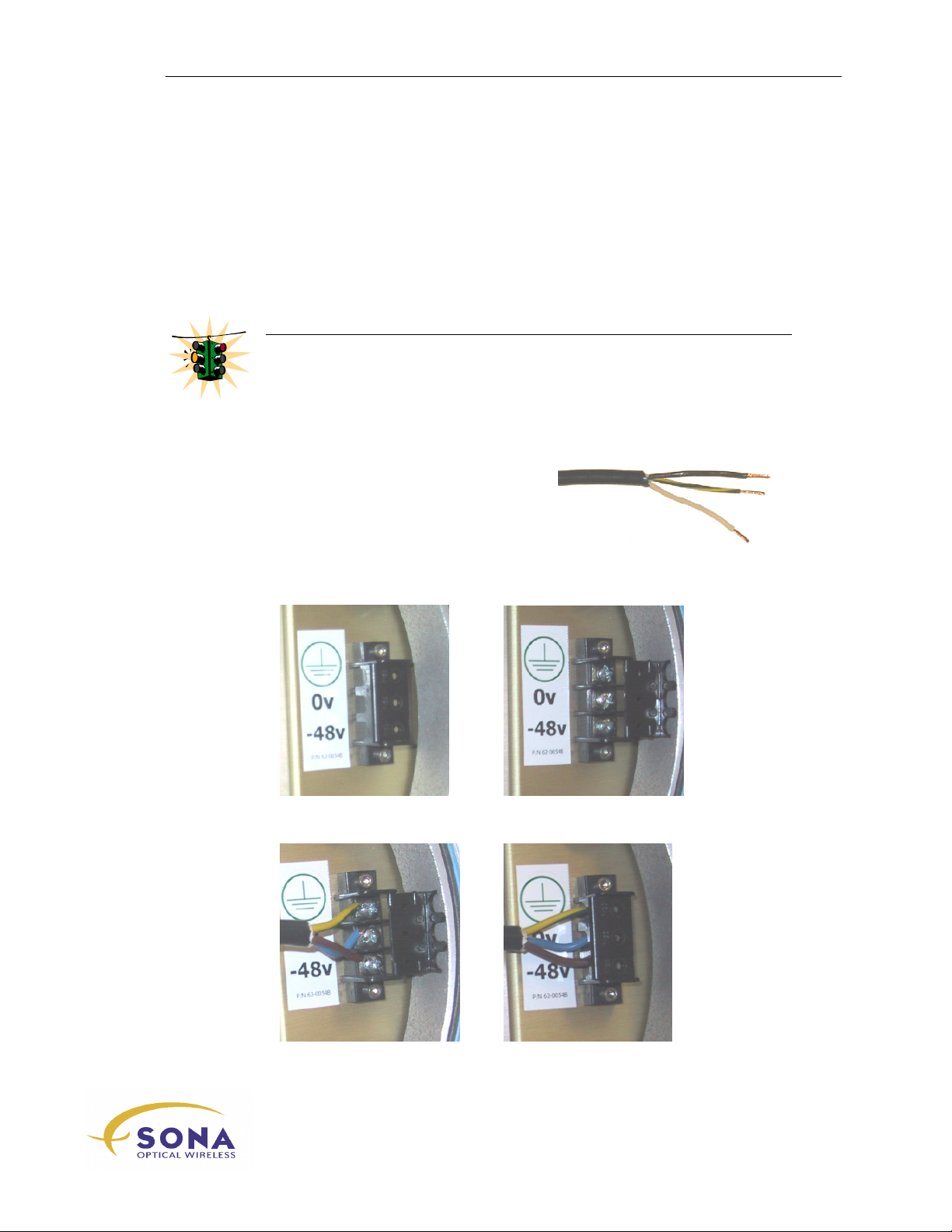
The SONAbeam E-Series terminal receives power at its Power Terminal Strip located in
the Customer Interface Area. Terminating your power cable entails preparing the end of
the power cable, opening the cover to access the power terminals, cinching each wire in
the power cable to its appropriate power terminal and replacing the cover.
These operations are detailed in this section…
WARNING!
Be sure power is DISCONNECTED at the source before terminating the power
cable!
To affix the Power Connector:
1.
Prepare the end of the power cable by
stripping 35mm (1¼”) of jacket from
the cable end and then stripping 6.5mm
(¼”) of insulation from the end of each
of the three wires, twisting them firmly
together...
2.
Snap open the Power Terminal Cover:
3.
Firmly attach your power cable wires and close the Power Terminal Cover:
-Series Installation Manual
wireless at the speed of light …………….
39
Page 50

Installing Your SONAbeam Terminal
SONAbeam Power Connections:
The following table provides a guide to assigning standard power cable wire colours to
associated power terminals:
Type I cable:
Wire Colour
GREEN GROUND GROUND
WHITE 0 V Neutral (Line)
BLACK -48 V Line
Type II cable:
Wire Colour
GREEN-YELLOW GROUND GROUND
BLUE 0 V Neutral (Line)
BROWN -48 V Line
DC Power Connections AC Power Connections
DC Power Connections AC Power Connections
NAbeam E-Series Installation Manual
40
wireless at the speed of light …………….
Page 51
Installing Your SONAbeam Terminal
Network Communications Cables
Your SONAbeam terminal interfaces your network traffic via an industry standard small
form-factor pluggable (SFP) transceiver. An assortment of interface SFP transceivers is
available as factory-installed options from fSONA Networks or you can provide your
own.
Installing Your Own SFP Transceiver
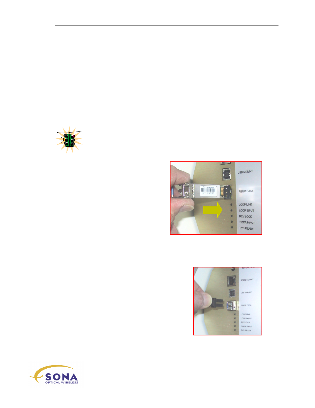
Carefully insert your SFP transceiver into the
13…
WARNING!
Be careful to orient the SFP transceiver correctly as shown!
Failure to correctly insert the transceiver may damage the transceiver AND the
terminal’s SFP transceiver cage!
FIBER DATA
port, as shown in Figure
Figure 13 – Inserting Your Interface
Transceiver
Factory Installed Interfaces
When your SONAbeam terminal in factory configured with an interface option, remove
the Dust Cap from the installed transceiver, as shown in Figure 14…
Figure 14 – Factory Installed SFP Transceiver
wireless at the speed of light …………….
-Series Installation Manual
41
Page 52
Installing Your SONAbeam Terminal
Fiber Optic Cables
NOTE…
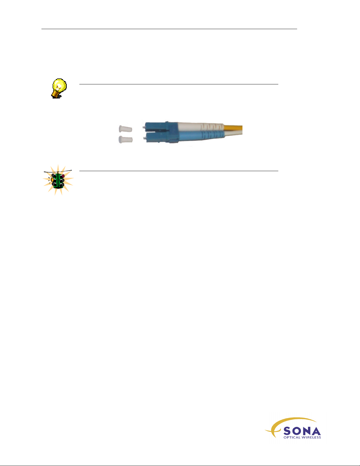
The fiber optic cables and their mating couplers are typically shipped with
protective caps to safeguard these sensitive components. These must be removed
just prior to mating the fiber optic cables to the SFP transceiver…
WARNING!
Be careful not to scratch the ends of the fiber cables where they protrude from
the fibre connectors!
When handling fiber optic cables, DO NOT bend them beyond their minimum
bend radius – typically 3” – or signal degradation or failure may ensue!
Never stare into the end of a ‘live’ fiber optic cable!
NAbeam E-Series Installation Manual
42
wireless at the speed of light …………….
Page 53
Installing Your SONAbeam Terminal
Terminal Management Connections
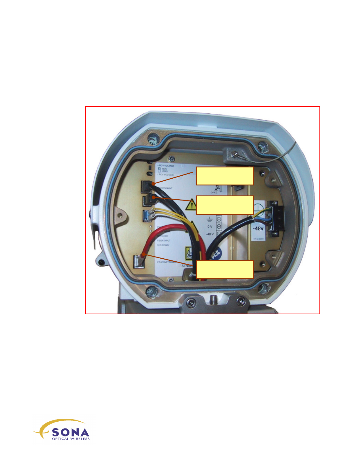
Your SONAbeam terminal provides three Terminal Management Ports: Serial (RS232),
USB and Ethernet, as shown in Figure 15.
Serial (RS232) Terminal
Management Port
USB Terminal
Management Port
Ethernet (LAN) Terminal
Management Port
Figure 15 – Completed Customer Interface (with all MGMT connections)
wireless at the speed of light …………….
-Series Installation Manual
43
Page 54
Installing Your SONAbeam Terminal
Pin 1
Terminal Mgmt RS232 Interface
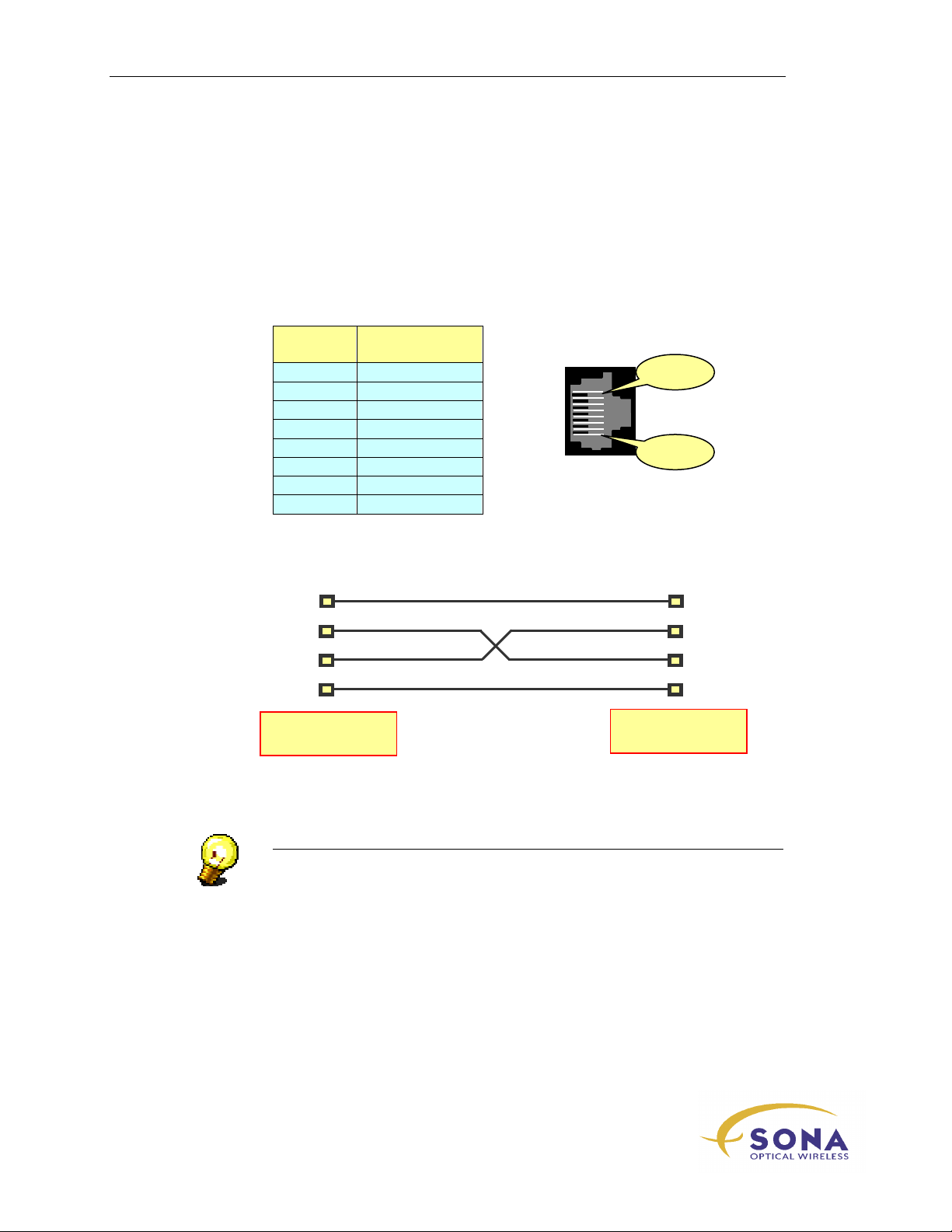
Your SONAbeam terminal supports a simple (RS232) serial interface to a PC’s COM
port for terminal monitoring and management. The connection between the SONAbeam
terminal and your PC is a standard, 3-wire (
running at 19,200 bits per second, formatted: 8 bits, 1 stop bit and no parity.
A standard 8 pin RJ45 modular connector is used with the following specification:
TX – RX – GND
) RS232-serial interface
Position
1
2
3
4 SG
5 RD
6 TD
7 CTS
8
Signal
Description
NC
NC
NC
NC
Pin 8
When connecting your PC’s COM port to the SONAbeam terminal, use a null-modem
configuration (with TD crossed to RD, and RD crossed to TD), as shown in Figure 16.
CTS
DTR
TD
RD
GND
SONAbeam Serial
Console Port
COM Port on
Host Computer
GND
Figure 16 – Typical SONAbeam – PC Interface
TD
RD
NOTE…
The computer’s COM port and the terminal’s serial console ports are both
configured as Data Terminal Equipment (DTE). A crossed (Null Modem) cable
connection is therefore required to successfully interface the two…
Your computer’s COM may also require looping RTSCTS and/or
DTRDCD in order to enable communications, depending on the
configuration of the COM port used.
NAbeam E-Series Installation Manual
44
wireless at the speed of light …………….
Page 55
Installing Your SONAbeam Terminal
Strain Relief for your Interface Cabling
In order to preserve the electrical safety rating of your SONAbeam terminal, the bundle
of interface cabling entering the terminal’s Customer Interface Area must include a strain
relief against someone pulling on one or more of these interface cables at the other end of
the interfacing conduit. A special strain relief is included in your terminal’s Installation
Kit for this purpose.
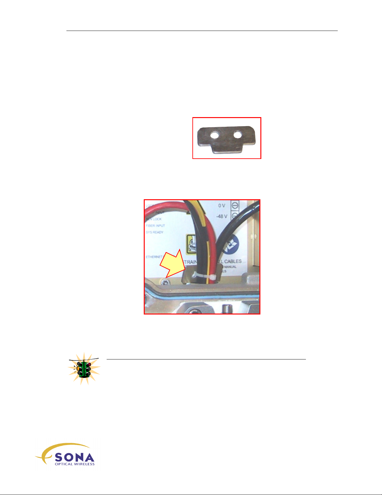
To install the Strain Relief:
1.
Obtain the special Strain Relief
from your Installation Kit:
2.
Position the special Strain Relief into the conduit entrance,
as shown in Figure 17.
3.
Using a cable tie (also part of your Installation Kit), secure the special strain relief
to the entire cable bundle where it enters the terminal, as shown in Figure 17.
Figure 17 – Completed Strain Relief of the Interface Cabling
WARNING!
Proper installation of the special Strain Relief is required to uphold
compliance of the electrical safety rating of your SONAbeam terminal!
-Series Installation Manual
wireless at the speed of light …………….
45
Page 56
Installing Your SONAbeam Terminal
Connections at the Customer Interface Box
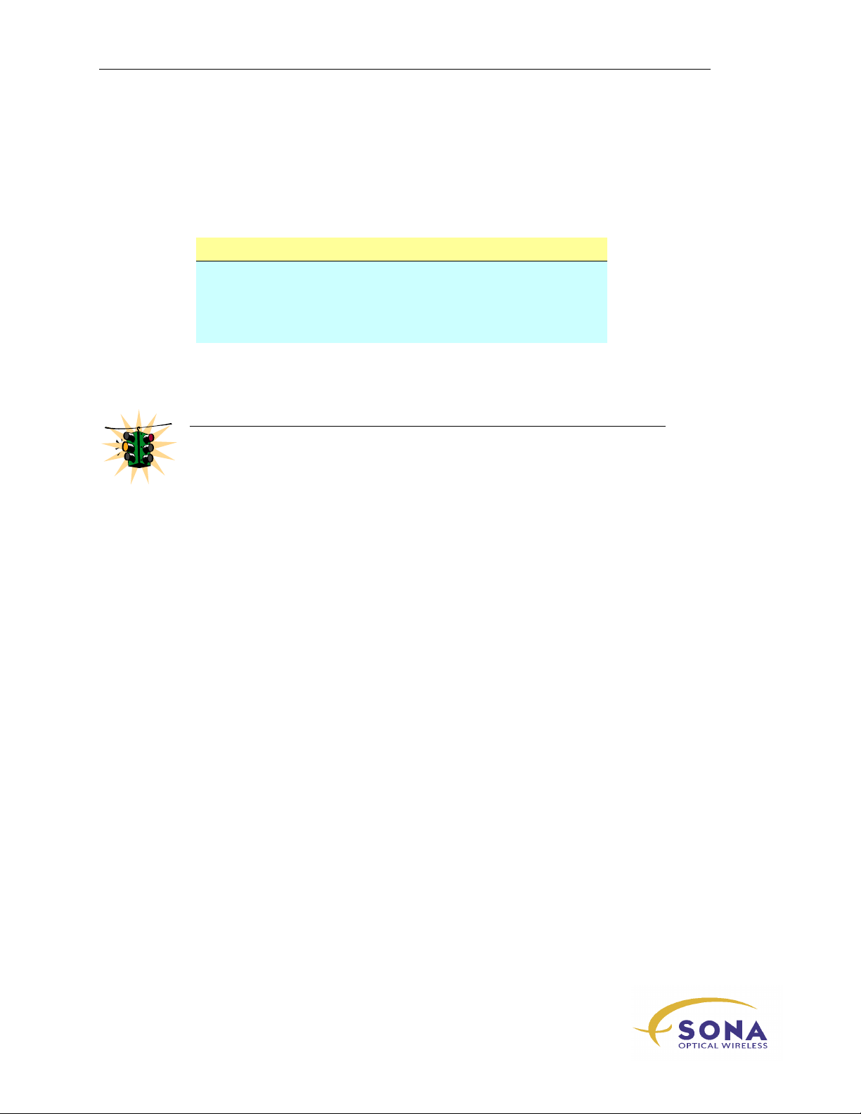
At your Customer Interface Box, connect the fiber optic cables to their appropriate
network connectors. The fiber optic cables connect to the network as follows:
Cable Designated Connection
TX
RX
At your Customer Interface Box, connect the power cable to your AC power source and
protective earth ground.
WARNING!
Be sure the terminal’s power switch is OFF before applying power to its power
cable!
At your Customer Interface Box, connect your applicable serial and/or USB and/or
Ethernet patch cable(s) to your system interface(s).
Network traffic TO your network FROM the
other SONAbeam terminal…
Network traffic FROM your network TO the
other SONAbeam terminal…
NAbeam E-Series Installation Manual
46
wireless at the speed of light …………….
Page 57

Initial Power Up and Terminal Configuration
Initial Power Up and
Terminal Configuration
With the SONAbeam terminal’s components installed and wired, you are ready to power
up and initialize the terminal and then proceed to align it with the terminal at the other
end of the communication link.
This section will cover the following activities:
Connecting a PC to monitor and set the internal operations of the SONAbeam…
Initial power up of the SONAbeam…
Monitoring and setting the SONAbeam for proper operation…
WARNING!
Double-check all of your wiring before applying power to the SONAbeam
terminal!
INFORMATION ALERT!
THE LASER DEVICES PRESENT WITHIN THIS EQUIPMENT ARE HAZARDOUS WHEN VIEWED
WITH OPTICAL INSTRUMENTS (BINOCULARS OR TELESCOPES). BOTH LASER
TRANSMITTERS HAVE THE FOLLOWING OUTPUT CHARACTERISTICS:
Laser Type Wavelength Avg. Output Power Peak Output Power
InGaAsP Laser Diode 1520 – 1580 nm 80 mW 160 mW
(Indium Gallium Arsenide Phosphide)
ALL SONAbeam models are:
ANSI-CLASS 1 laser product – According to ANSI Z136.1 & Z136.6
IEC-CLASS 1M laser product – According to IEC60825-1 Amendment 2:2001
CDRH-CLASS IM laser product – Complies with 21 CFR 1040.10 and 1040.11 except for deviations
pursuant to Laser Notice No. 50, dated July 26, 2001
wireless at the speed of light …………….
47
-Series Installation Manual
Page 58
Initial Power Up and Terminal Configuration
WARNING!
BEFORE CONNECTING THIS TERMINAL TO YOUR LAN!
This terminal is shipped from the factory with the following IP settings:
To avoid a conflict with another device on your LAN, you should adjust your
terminal’s IP settings using a serial connection prior to attaching the terminal to
your network.
IP Address 192.168.55.161
Subnet Mask 255.255.255.0
Gateway 192.168.55.254
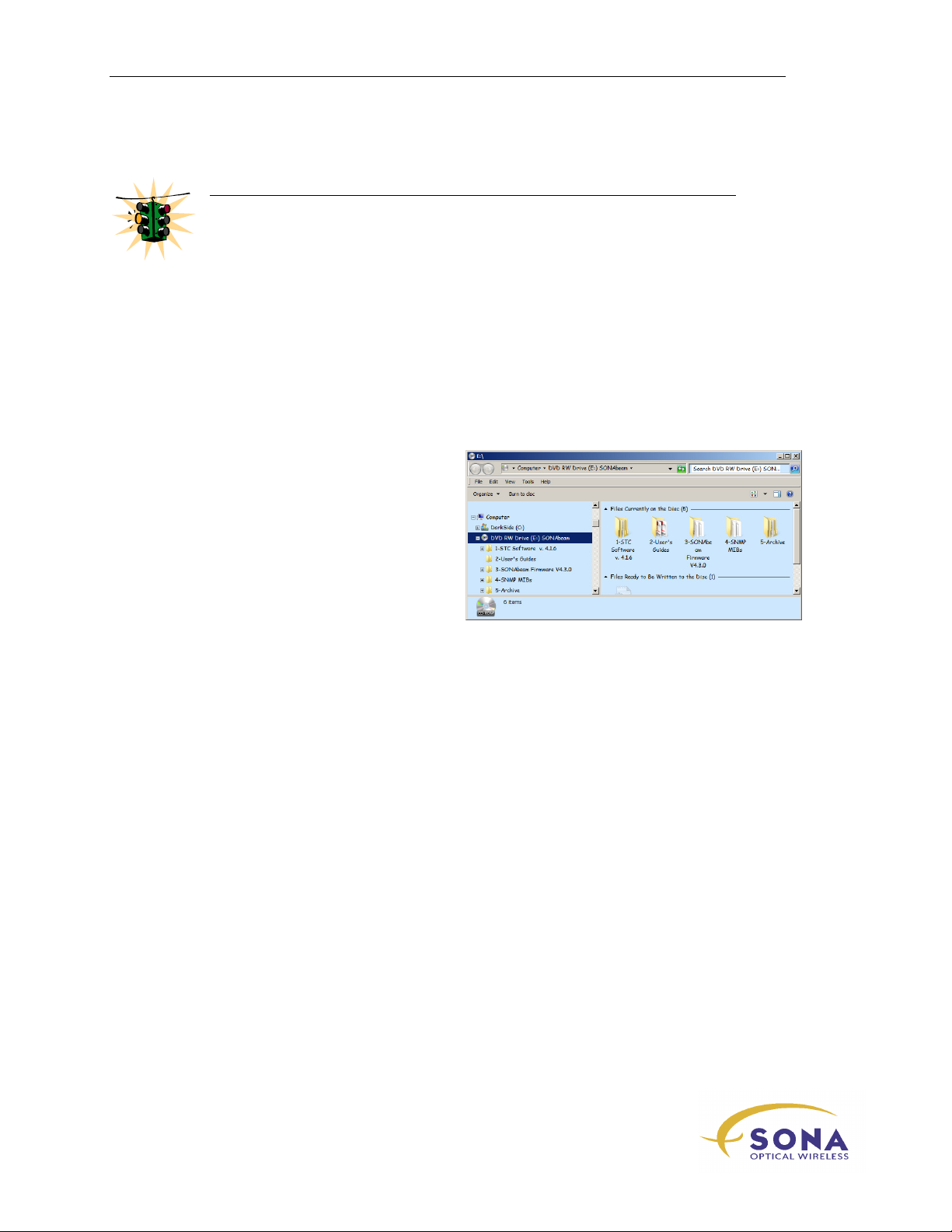
SONAbeam Utilities CD
Your SONAbeam Installation Kit includes a
SONAbeam SW Utilities CD, which
provides you with tools and information to
help successfully make your FSO link.
The CD is organized in five subject folders:
1 – STC software allows you to configure
and monitor your SONAbeam terminals.
2 – User Guides holders installation and
user information.
3 – Terminal Firmware contains files for firmware recovery.
4 – SNMP MIBs provides files for Simple Network Management Protocol option.
5 – Archive holds previous versions of STC software and terminal firmware.
SONAbeam Terminal Controller Software
Install the SONAbeam Terminal Controller (STC) Software from the Utilities CD so you
can monitor your terminal’s operating parameters, retrieve identification information and
other factory settings and set up your terminal for your link and network.
The SONAbeam Terminal Controller software can be used at this stage for the following:
To provide verification of terminal operating parameters when it is first
powered up…
To allow configuration of applicable terminal option settings.
To monitor terminal operation
Additionally, the SONAbeam Terminal Controller software can also be used in the
alignment stage of your SONAbeam link installation.
NAbeam E-Series Installation Manual
48
wireless at the speed of light …………….
Page 59
Initial Power Up and Terminal Configuration
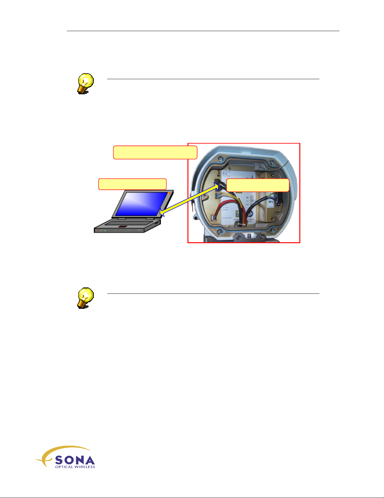
SONAbeam Terminal
PC (with STC Software)
Serial/USB Interface
NOTE…
Refer to the SONAbeam Terminal Controller Software User Guide for
information on installing and using the software on your computer…
Connecting a PC to your SONAbeam Terminal
A temporary setup connection between your PC w/STC and the SONAbeam is made
through a simple serial or USB interface, as illustrated in Figure 18.
Figure 18 – Connecting your new SONAbeam to STC Software
Simply use a suitable cable to connect your Terminal Controller (PC) to the appropriate
RS232 MGMNT
Area.
or the USB
NOTE…
If your installation includes a permanent serial interface to your SONAbeam,
temporarily disconnect it while performing the initial terminal setup…
MGMNT
connector inside the terminal’s Customer Interface
USB Connection
A Universal Serial Bus (USB) connection is a simple plug n’ play affair using a standard
Type A to Type B USB cable. (One is supplied in the optional Basic Alignment Kit.)
wireless at the speed of light …………….
-Series Installation Manual
49
Page 60
Initial Power Up and Terminal Configuration
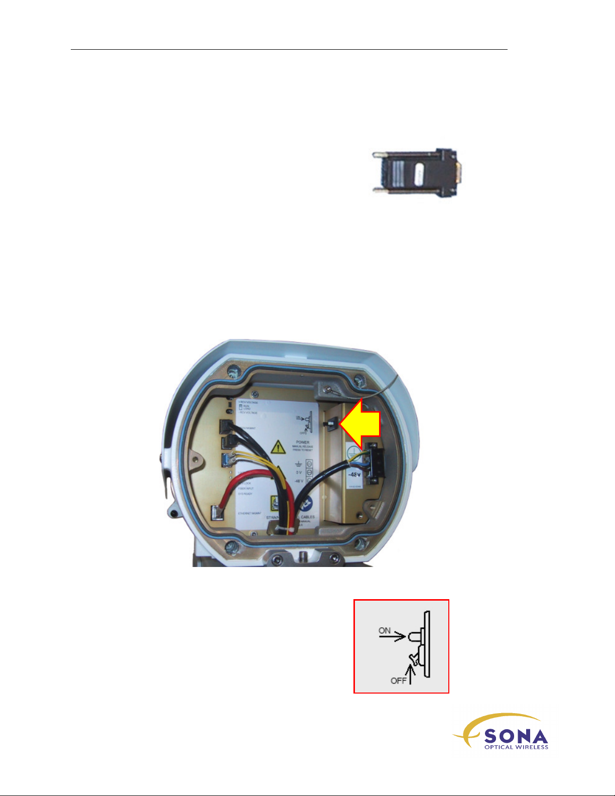
RJ45 Serial Adapter
To facilitate the connection of the SONAbeam to your PC, a
serial cable adapter is included as part of the optional Basic
Alignment Kit. This adapter provides a Null Modem
interface as well as adapting the computer’s serial port –
typically a DB-9 type connector – to an RJ45 type
connector.
Use this adapter with any standard, straight-through CAT5
cable with RJ45 ends.
SONAbeam Terminal Power Up
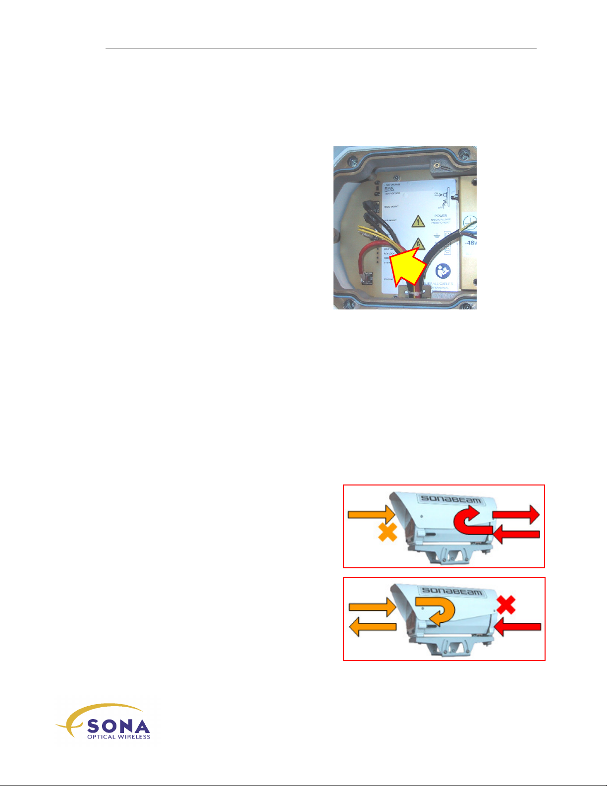
Your SONAbeam E-Series terminal is equipped with a resettable circuit protector with a
manual release mechanism, located in the terminal’s Customer Interface Area, as shown
in Figure 19. This combines the functionality of a power switch with the protection and
convenience of a resettable circuit breaker.
Figure 19 – Terminal’s Resettable Circuit Protector
Operating this circuit switch/protector is illustrated here:
NAbeam E-Series Installation Manual
50
wireless at the speed of light …………….
Page 61
Initial Power Up and Terminal Configuration
Verifying Initial Power Up Operation
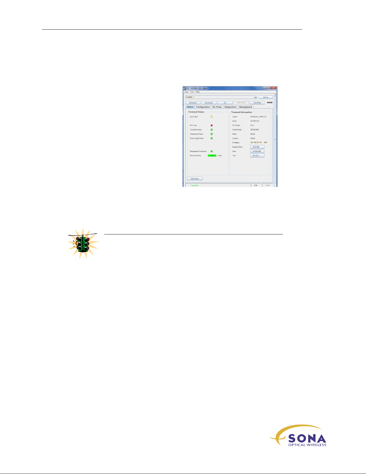
The E-Series terminal offers you a number
of indicator LED’s in the Customer Interface
Area to convey the operational status of
your terminal.
These operational indicators are described
below.
Figure 20 – Terminal’s Status LED’s
SONAbeam Terminal Status LED’s
Your SONAbeam E-Series terminal provides the following operational status indicators:
SYS READY –
indicate the terminal is powered on. After a few seconds the LED will FLASH on & off
to indicate your terminal is ready for operation.
FIBER INPUT –
network on the RX fibre (or wired input depending on the terminal’s SFP transceiver) and
it synchronizes with the terminal’s configured Data Rate.
RCV LOCK –
signal is locked to the crystal-controlled Data Rate that is currently configured for
terminal. (When your terminal is configured to operate in
crystal-controlled data rate, this LED is always OFF.)
LOOP INPUT –
terminal is currently configured (temporarily for
diagnostics using STC software) so that the fibre
(or copper) signal received at the terminal’s RX
port is transmitted back directly to its TX port,
with no FSO signal transmitted. This condition
allows you to test your network cabling to your
terminal.
LOOP LINK –
terminal is currently configured (temporarily for
diagnostics using STC software) so that the FSO
signal that it receives is transmitted back directly
to the other terminal, bypassing all transceiver
circuitry. This condition allows you to test your
FSO link.
When power is applied to the terminal, this LED initially illuminates to
This LED indicates that your terminal detects an input signal from your
This LED indicates that your terminal’s incoming free-space received
Bypass
mode or at a non
This LED indicates that your
This LED indicates that your
-Series Installation Manual
wireless at the speed of light …………….
51
Page 62
Initial Power Up and Terminal Configuration
Verifying Power Up Operation with STC
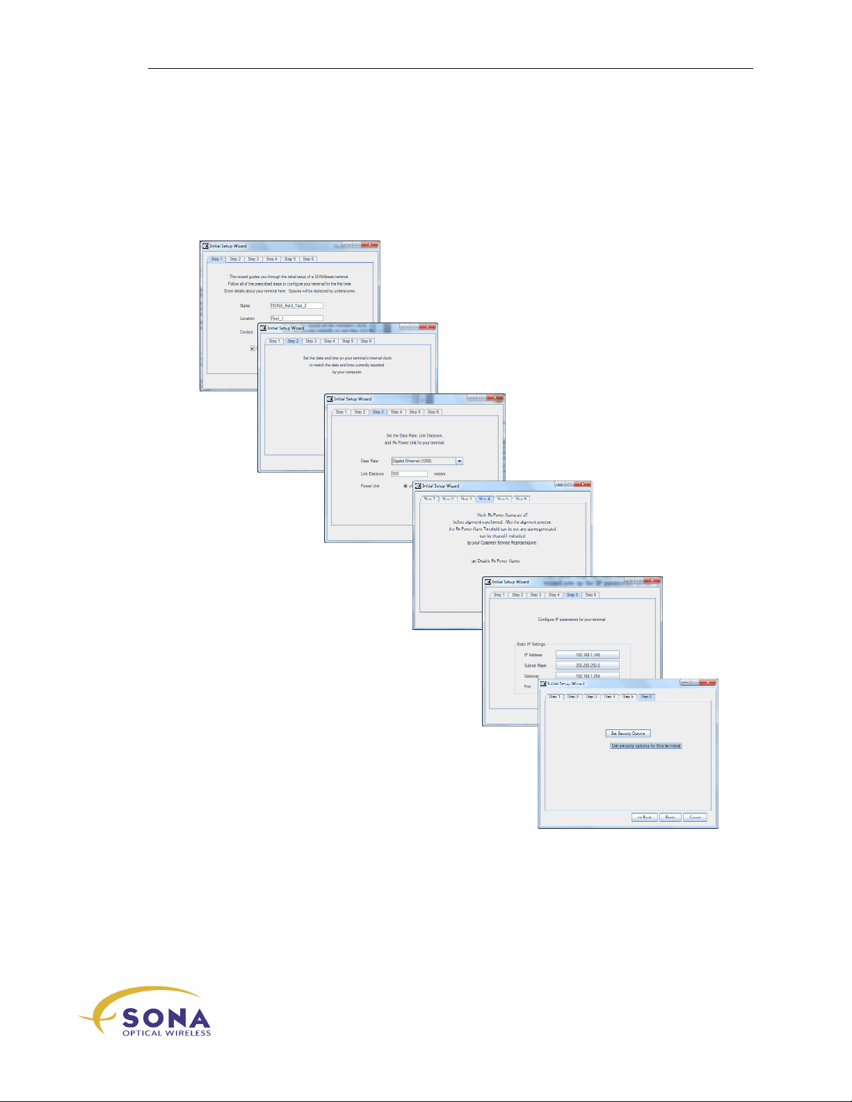
To verify that your SONAbeam is in fact
powered up and functioning, use your PC with
the SONAbeam Terminal Controller (STC)
software. Following the instructions found in
the section: Setting Up a New SONAbeam
Terminal/Link in the STC User’s Guide,
connect to the SONAbeam and verify that the
terminal reports itself as ready-to-go, as shown
in Figure 21.
Figure 21 – SONAbeam Terminal
Controller – Status Window
When your SONAbeam is operating properly, the
successful connection, identifying the terminal and the
display valid values for the prescribed SONAbeam parameters.
WARNING!
If the STC software fails to connect with the terminal, remove power
from the terminal and re-check all of your interface wiring!
Also confirm that the COM port selection for the STC software
coincides with the correct physical (PC) COM port used on your STC
host computer.
STC Status
STC Diagnostics
window will report a
Setting Up your SONAbeam Terminal
There are three initial SONAbeam setups that should be performed at this time:
FSO data rate (Unless Default Data rate applies)
SONAbeam laser power (Unless Default Data rate applies)
SONAbeam terminal configuration, including network IP addressing
All of these operations can be readily performed using the
Wizard
SONAbeam.
that is part of the SONAbeam Terminal Controller software included with your
Initial Configuration
window will
See the SONAbeam Terminal Controller Software User’s Guide for more information.
NAbeam E-Series Installation Manual
52
wireless at the speed of light …………….
Page 63
Initial Configuration Wizard
Initial Power Up and Terminal Configuration
The STC software provides a self-starting
Initial Configuration Wizard
that sets up
your new terminal for immediate deployment: (See the SONAbeam Terminal Controller
Software User’s Guide for more information.)
1 – Terminal identification…
2 – Set the terminal’s real-time clock…
3 – Set data rate *…
4 – Ready the terminal for alignment…
5 – Set the terminal network properties…
6 – Set the terminal security properties…
*
See your SONAbeam Terminal Controller Software User’s Guide – Appendix A -
SONAbeam Data Rates for more information...
-Series Installation Manual
wireless at the speed of light …………….
53
Page 64
Initial Power Up and Terminal Configuration
6 o’clock
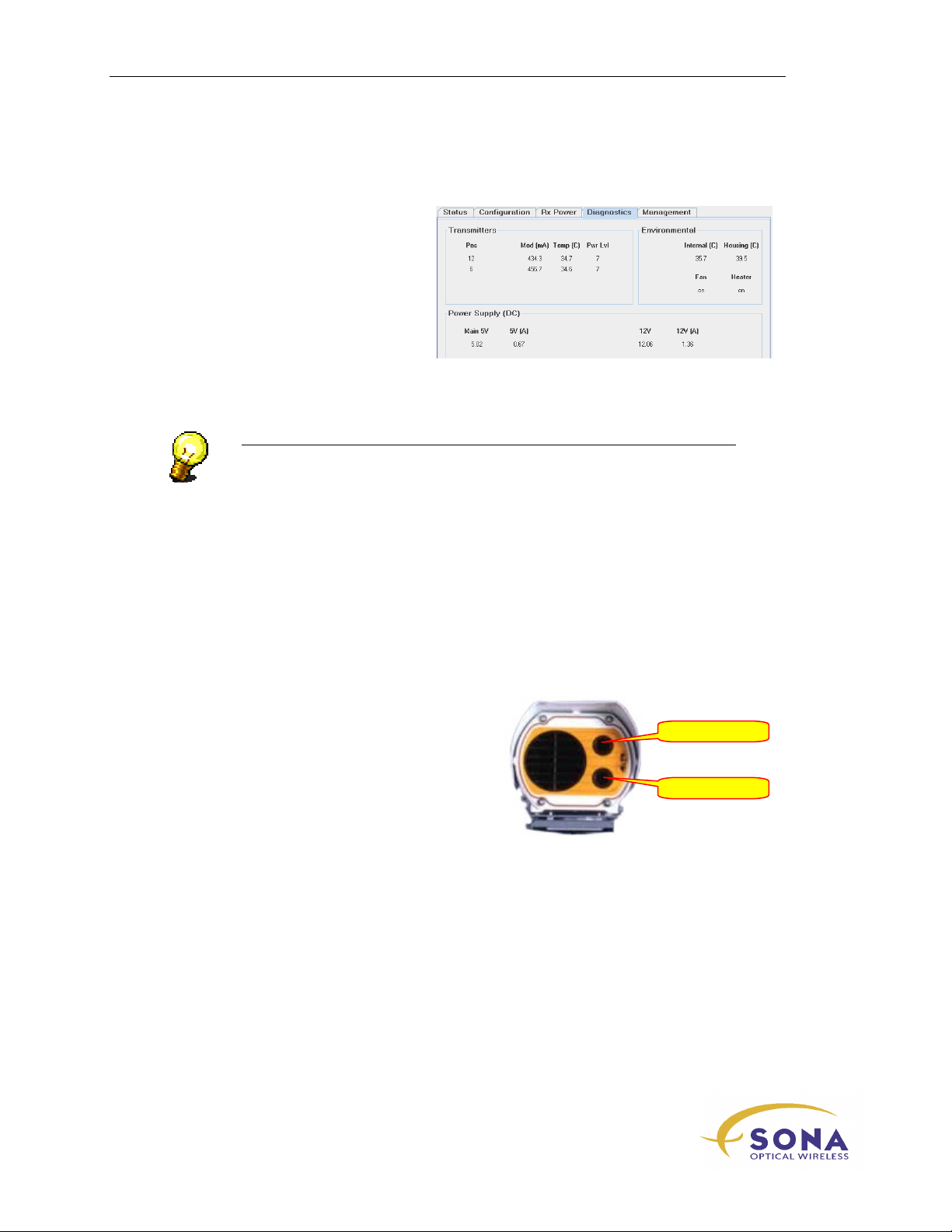
SONAbeam Diagnostics
After completing the initial
Configuration Wizard, view the STC’s
Diagnostics
terminal operating parameters, to finalize
the initial power-up verification process.
screen, which reports your
Figure 22 – SONAbeam Terminal Controller – Diagnostics Window
NOTE…
Perform the initial setup to both SONAbeam terminals when building an
FSO link…
SONAbeam Transmitter Orientations
The two optical transmitters on the
SONAbeam E-Series are referred to by their
relative clock-face positions, as shown in
Figure 23
Figure 23 – SONAbeam E-Series
Transmitter Orientations
12 o’clock
NAbeam E-Series Installation Manual
54
wireless at the speed of light …………….
Page 65
Network Connection for Alignment
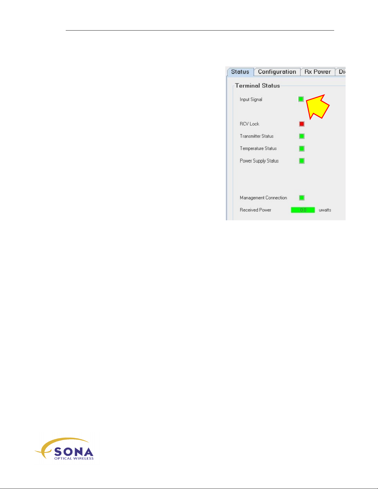
An input network signal is required to align your
FSO link.
With your Data Rate set in the previous section and
live network traffic connected, both your terminal
status LED and STC should indicate
Input Signal
Initial Power Up and Terminal Configuration
.
wireless at the speed of light …………….
-Series Installation Manual
55
Page 66

Initial Power Up and Terminal Configuration
NAbeam E-Series Installation Manual
56
wireless at the speed of light …………….
Page 67

Aligning Your SONAbeam Terminals
Aligning Your
SONAbeam Terminals
The alignment of your SONAbeam terminals is crucial to achieving optimal performance
with your link. The procedure to achieve alignment entails a systematic ‘search’ for an
optical signal from the associated (remote) terminal.
Both terminals in a link must be aligned in concert with each other. Therefore, you will
need to provide the tools, personnel and resources at both ends of the installed link while
executing the alignment phase of your installation.
This section describes the alignment procedure for the SONAbeam E-Series terminal.
NOTE…
The alignment of linking terminals is an extremely important operation. The care
and attention invested in this operation will directly reflect in the performance of
your optical link…
Before You Begin…
The tools required to successfully align a SONAbeam terminal include:
5mm Allen wrench (available in the optional Basic Alignment Tool Kit)…
SONAbeam Alignment Telescope Assembly (available in the optional Basic
Alignment Tool Kit)…
Notebook Computer with the SONAbeam Terminal Controller software
installed…
Serial or USB cable to interface the PC with the Terminal …
As an alternative to using a computer with STC software and the serial cable, a
suitable digital voltmeter can be used.
A means of communications between the installation personnel at both link
sites… (While cell phones are an ideal solution, ‘walkie-talkies’ can also
accommodate this function.)
NOTE…
As a link comprises two terminals, your alignment toolkit will require two of
everything in order to provide a complete alignment kit at each end of your
link…
-Series Installation Manual
wireless at the speed of light …………….
57
Page 68
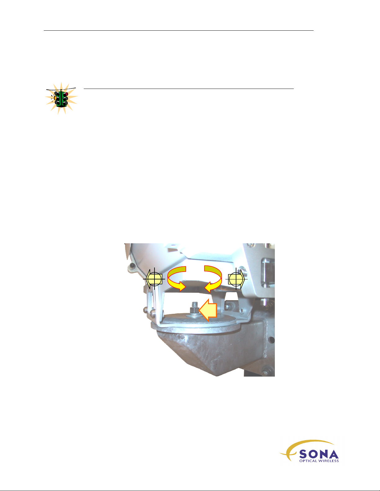
Aligning Your SONAbeam Terminals
WARNING!
Ensure that no one stands directly in front of either SONAbeam terminal while
aligning them! To do so may interfere with the optical communications between
the two terminals…
Alignment Adjustments
The Mounting Plate is equipped with both coarse and precise tuning controls for
elevation and azimuth alignment for adjusting the combined transmit and receive axis of
the mounted optical head. This section describes these controls…
Coarse Azimuth Adjustment
Coarse azimuth adjustment is achieved by loosening the nut that secures the terminal’s
mounting plate to the Mount and then rotating the mounting plate (and optical head) as it
sits on the Mount, as shown in Figure 24.
Figure 24 –Coarse Azimuth Adjustment
NAbeam E-Series Installation Manual
58
wireless at the speed of light …………….
Page 69

Aligning Your SONAbeam Terminals
Coarse Elevation Control
Coarse elevation adjustment is provided by the terminal’s mounting plate, as shown in
Figure 25. Using a 5mm Allen wrench, loosen the four screws (two on each side) to the
point were you can pivot the optical head on the rear screws for positive elevation, or
pivot the optical head on the front screws for negative elevation adjustment.
Figure 25 – Coarse Elevation Adjustment
The mounting plate provides approximately ±30° of elevation adjustment.
wireless at the speed of light …………….
59
-Series Installation Manual
Page 70
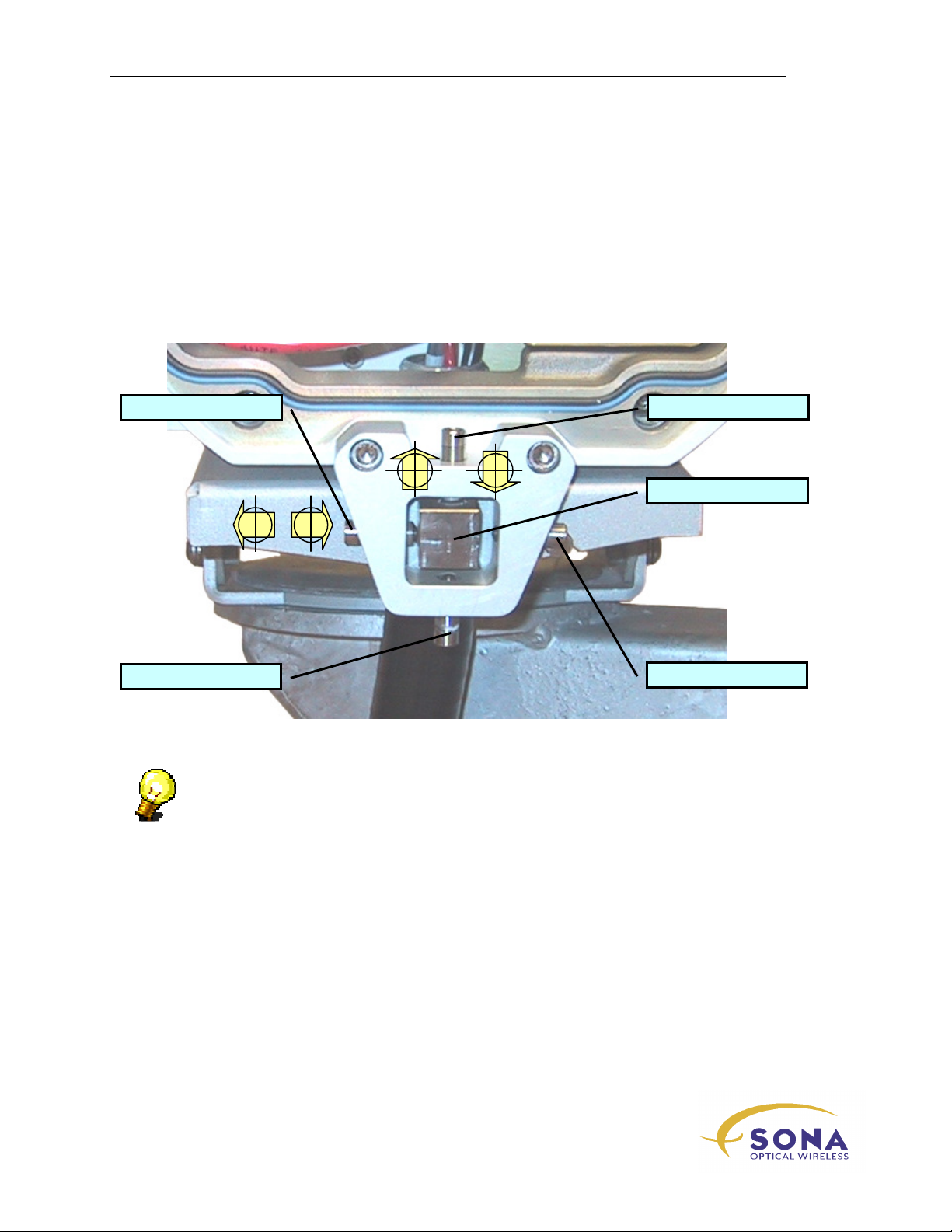
Aligning Your SONAbeam Terminals
Fine Azimuth & Elevation Tuning
Fine-tuning of the terminal’s azimuth and elevation alignment is controlled by the fourpoint alignment yoke and steering block located at the rear of the terminal’s mounting
plate, as shown in Figure 26.
In combination with a tensioning spring in the mounting plate, the two tuning screws
provide precise alignment tuning, while the associated locking screws lock in your
adjustment when alignment is completed.
Azimuth Tuning Screw
Elevation Locking Screw
NOTE…
As a link comprises two SONAbeam terminals, your alignment toolkit will
require two of everything in order to provide a complete alignment kit at each
end of your link…
Elevation Tuning Screw
Alignment Steering Block
Azimuth Locking Screw
Figure 26 - Fine Tuning Alignment Controls
NAbeam E-Series Installation Manual
60
wireless at the speed of light …………….
Page 71
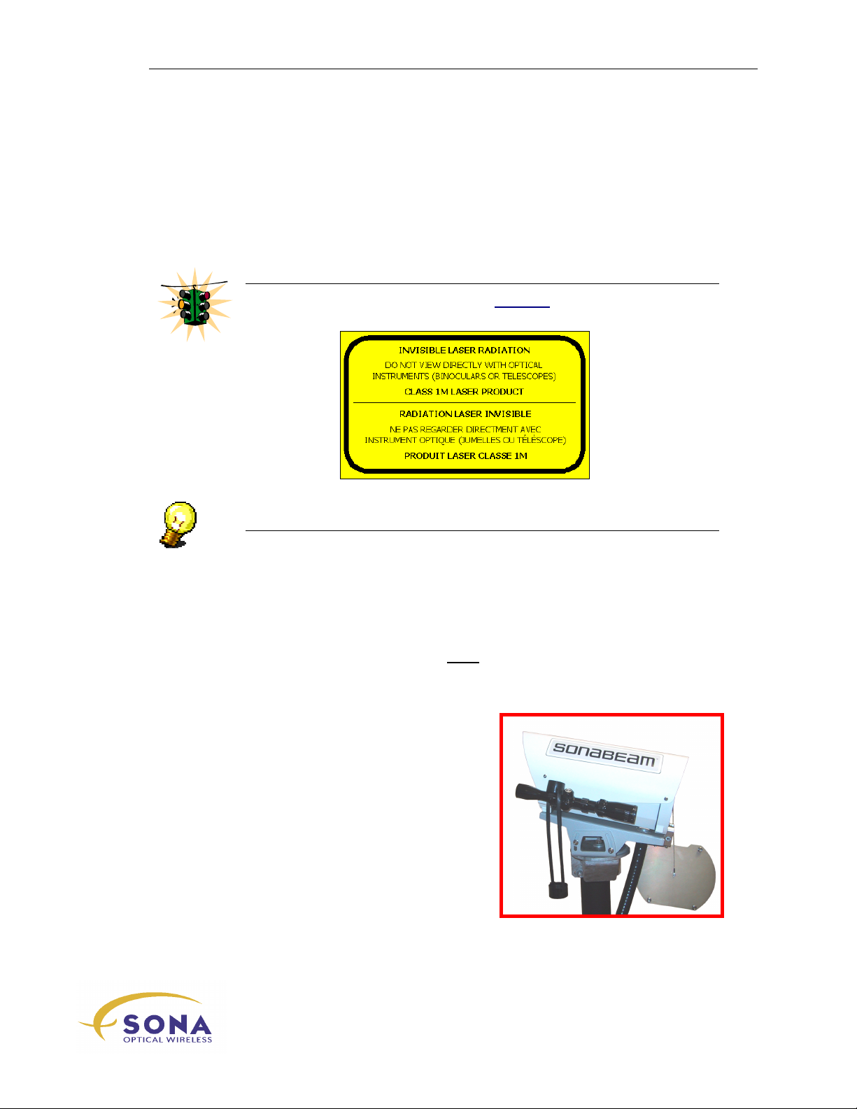
Aligning Your SONAbeam Terminals
Stage 1 – Visual Alignment
The initial visual alignment stage is necessary to establish terminal alignment within the
terminal’s field of view to be able to use a measured alignment procedure described later
in this guide.
WARNING!
NEVER use optical instruments to view an operating SONAbeam terminal at a
range closer than 50 meters (170 feet)!
NOTE…
The visual alignment stage is meant to get your alignment close enough to be able to use
the alignment tuning controls for the next stage. To achieve visual alignment, proceed as
follows:
The Alignment Telescope provided by fSONA is altered with a special spectral
filter that lets you safely view a SONAbeam terminal.
1.
Power both SONAbeam terminals OFF!
2.
Mount a SONAbeam Alignment Telescope (part of the optional Basic
Alignment Kit) onto each optical head, as shown in Figure 27.
Figure 27 – Attached Alignment Telescope
wireless at the speed of light …………….
-Series Installation Manual
61
Page 72
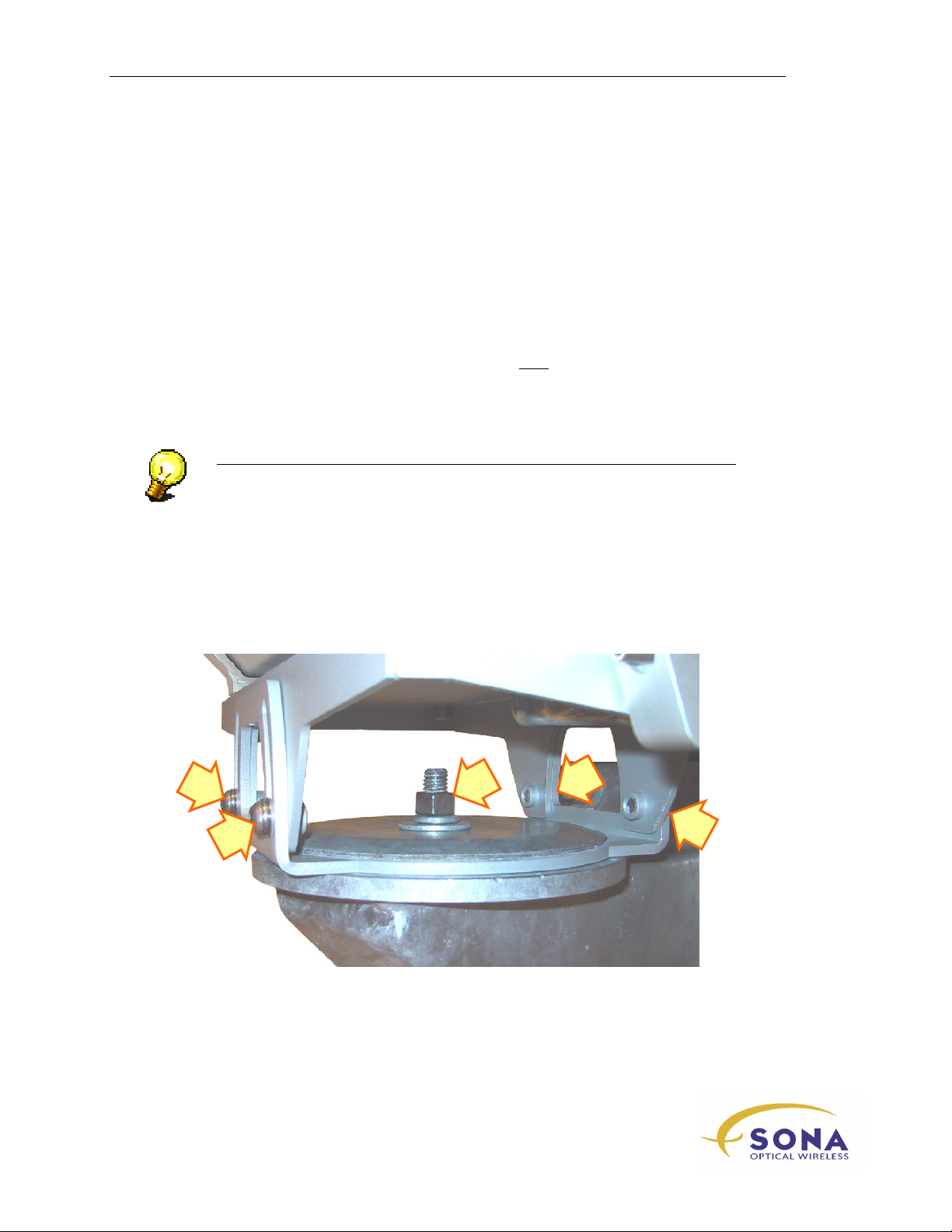
Aligning Your SONAbeam Terminals
3.
Centre the alignment steering block, as shown in Figure 26.
4.
Using the terminal’s coarse azimuth and elevation controls, manually point each
optical head in the general direction of its associated terminal at the other side of
your link.
5.
Using the attached Alignment Telescope as a viewfinder, carefully make
azimuth and elevation adjustments to aim each optical head at its associated
SONAbeam terminal at the other end of the link. (Target the associated terminal
as best you can by using the coarse alignment controls.)
6.
Lock the coarse alignment adjustment in place by tightening the locking plate
nut and the four elevation screws until they are snug.
7.
When you can sight the face of the SONAbeam terminal at the other end of the
link, use the fine-tuning adjustment screws to ‘target’ the associated SONAbeam
terminal in the cross hairs of the Alignment Telescope.
NOTE…
It is important to get the coarse alignment as close as possible to maximize the
usable range of the fine-tuning adjustment mechanism.
Aligning the terminals to each other with the Alignment Scope does not
necessarily mean that a signal will be immediately acquired. The Alignment
Scope will get you close, but a search routine is likely required to find and
maximize the signal.
Figure 28 - Locking Coarse Alignment
NAbeam E-Series Installation Manual
62
wireless at the speed of light …………….
Page 73
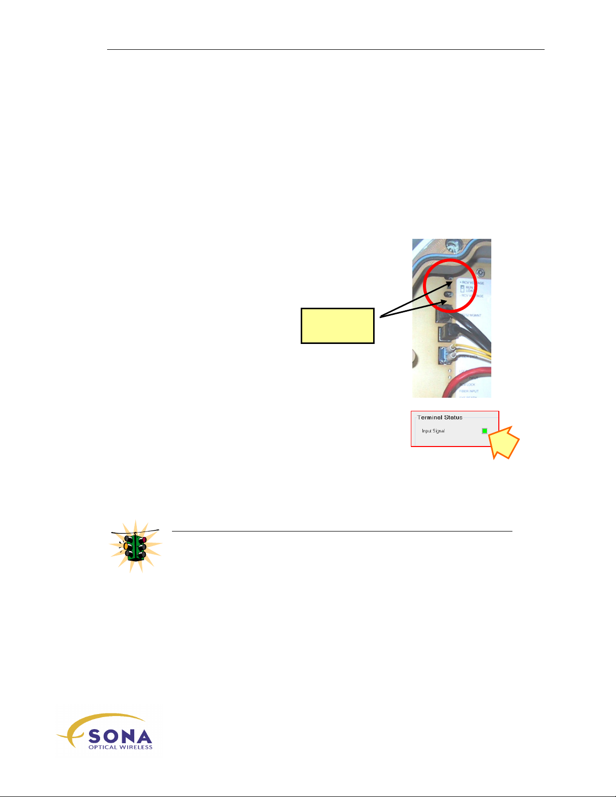
Aligning Your SONAbeam Terminals
Stage 2 – Finding your FSO Signal
With BOTH associated SONAbeam terminals visually aimed at each other, you are now
ready to commence the process of precisely aligning both terminals using a measurement
of the terminal’s received optical power. To accomplish this operation, you will need the
following for EACH SONAbeam terminal:
A local notebook computer with SONAbeam Terminal Controller (STC)
software attached to the SONAbeam’s
port…
OR…
A digital voltmeter to monitor the
points, located in the Customer Interface Area, as
shown in Figure 29.
TERMINAL MGMNT RS232
RCV SIG OUT
Voltmeter
terminals
test
(or USB)
Figure 29 – Digital Voltmeter -
Signal Strength Terminals
AND…
Live network connections to each SONAbeam terminal
or a connected fiber optic loop between the terminals
TX
and RX ports… (This is necessary to stabilize the
laser transmission on both SONAbeam terminals.)
Aligning your SONAbeam terminals will comprise a systematic ‘search’ for the centre of
the combined optical signal from the terminal at the other side of the link, as registered
by a maximum received signal measured with the STC software, or digital voltmeter
measurement.
WARNING!
Align one terminal at a time, alternating between the two sides to iteratively
maximize your alignment.
Position yourself behind the optical head when making alignment adjustments so
as not to block the transmit and receive beams!
To conduct the measured alignment of your SONAbeam Terminals:
1.
Connect a notebook computer to each of your SONAbeam terminals, as
described in the SONAbeam Terminal Controller Software User’s Guide…
(Or, connect your digital voltmeters to the
terminal.)
RCV SIG OUT
test points on each
-Series Installation Manual
wireless at the speed of light …………….
63
Page 74
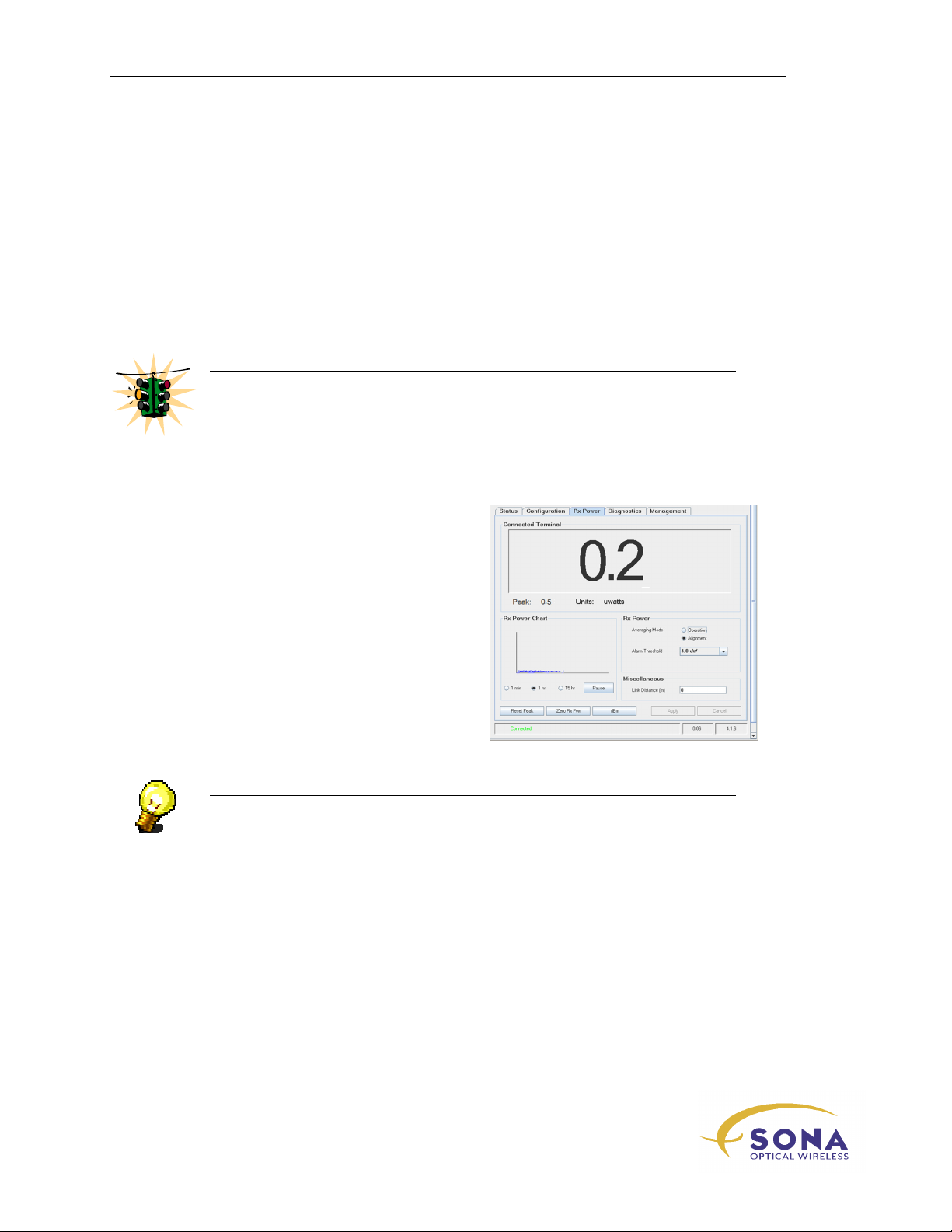
Aligning Your SONAbeam Terminals
2.
Terminate the RX and TX network connections on both SONAbeam terminals
through a loop connection or with a live network connection…
3.
Power up both SONAbeam terminals…
4.
If you are using STC, power up both notebook computers and launch their STC
software programs…
(Or, connect your digital voltmeter and set it for DC volts.)
WARNING!
If your SONAbeam terminals are located closer than 250 meters (820 feet) apart,
you will need to implement laser attenuation using the SONAbeam Terminal
Controller software…
Refer to the SONAbeam Terminal Controller Software User’s Guide for more
information…
5.
On both notebook computers, start the
RX Power
SONAbeam Terminal Controller
Software User’s Guide. This should
produce a screen similar to that shown
opposite on both computers…
display, as described in the
(A small value, typically less than 1
µW, is caused by the offset voltage of
the receiver circuitry.)
NOTE…
Maintain constant communications with the installation crew at the other end of
the link as you proceed to assess the effects of your alignment operation…
NAbeam E-Series Installation Manual
64
wireless at the speed of light …………….
Page 75
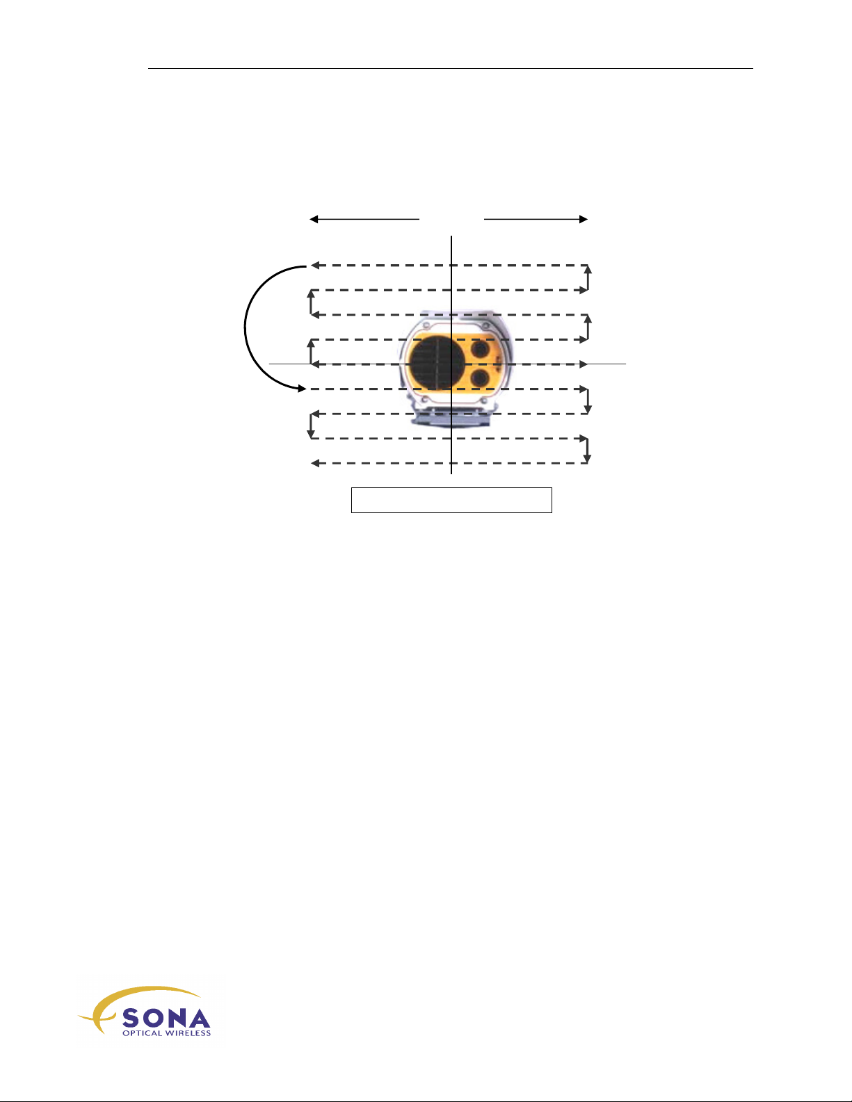
Aligning Your SONAbeam Terminals
1 Tur
n Elevation Increments
8 turns
Working with ONE SONAbeam terminal at a time, and referring to Figure 30, proceed
to align your link as follows:
1 turn
1 turn
5 turns
1 turn
1 turn
1 turn
1 turn
1 turn
Figure 30 – Recommended Alignment Search Pattern
6.
Use the alignment scope to visualize the size of the search grid you are trying to
scan with the adjustment screws. The grid is about 12m X 12m as a distance of
1000m, which corresponds roughly to plus/minus four full turns on the finetuning adjustment screws. The grid size scales proportionally with distance.
7.
Using only the azimuth tuning screw, slowly pan the optical head all the way to
the right and then all the way to the left while noting any significant increase in
the receive signal strength AT THE OPPOSING TERMINAL.
8.
Using only the elevation tuning screw, increase the terminal’s elevation by 1
complete turn.
9.
Repeat Step 7 & Step 8 in sequence until a signal is reported - AT THE
OPPOSING TERMINAL – or until the elevation has been increased to its
maximum.
10.
11.
If a signal is not yet found, re-centre the terminal’s alignment to its original
starting position and repeat this same sequence (Steps 7 – 9) but this time
DECREASING the terminal’s elevation by 1complete turn.
When a signal is reported AT THE OPPOSING TERMINAL, slowly pan left &
right and then up & down seeking to maximize the reported Rx Power with the
other installer calling out the observed Rx Power in real time.
wireless at the speed of light …………….
65
-Series Installation Manual
Page 76
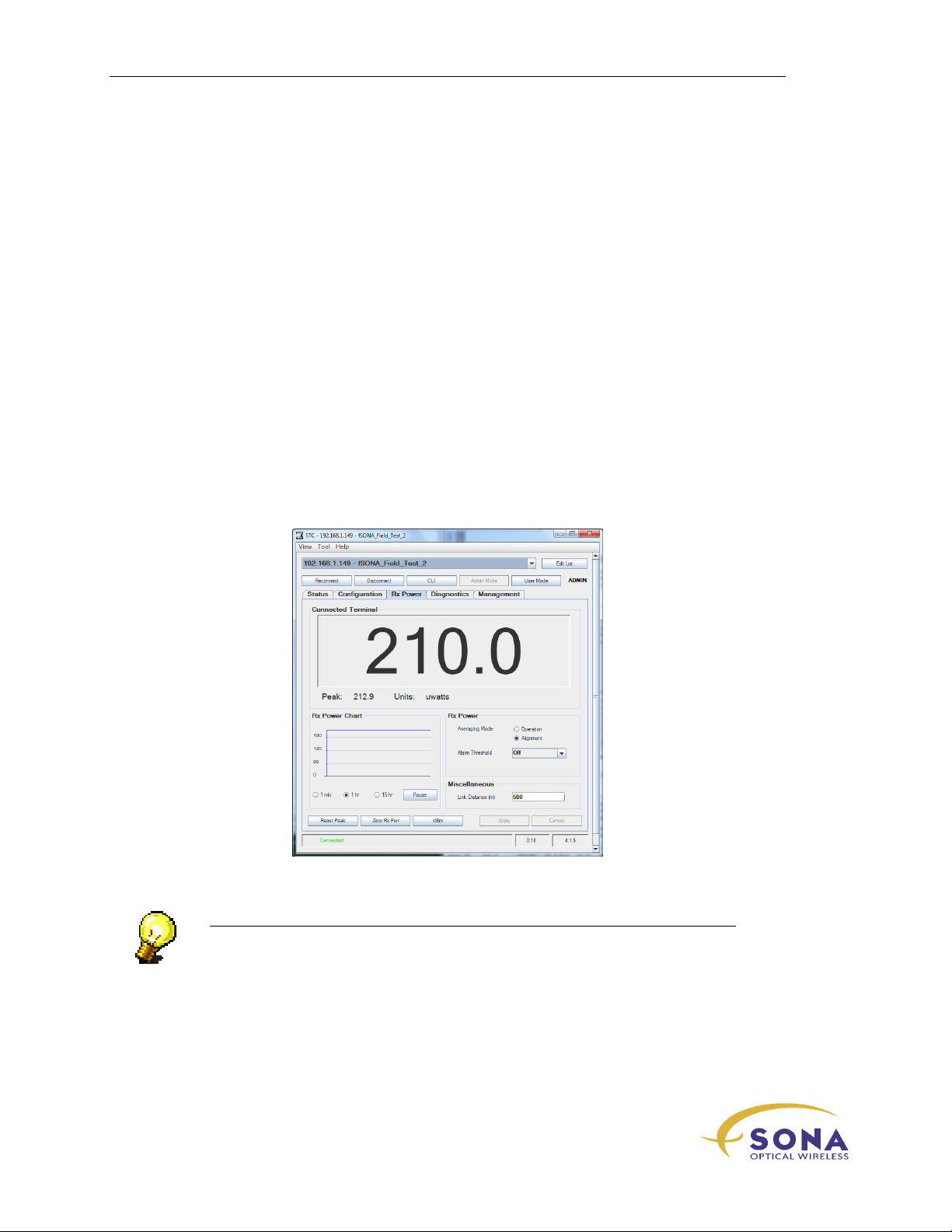
Aligning Your SONAbeam Terminals
12.
Once you have adjusted for maximum Rx Power, stop and have the other side
perform Steps 7 – 10 while you report the observed Rx Power to the other
installer in real time.
If a signal still cannot be found, re-centre the steering blocks on BOTH terminals to
their original starting positions and repeat this whole procedure but starting at the
OTHER side first..
Stage 3 – Fine Tuning your Alignment
Once both SONAbeam terminals have attained a received signal, proceed to alternately
fine tune ONE TERMINAL AT A TIME for optimum receive signal strength by
‘tweaking’ the azimuth and elevation of each SONAbeam terminal in small incremental
adjustments.
Alternate your fine-tuning adjustments on each SONAbeam terminal, ONE AT A TIME,
until no further improvement can be noted.
Figure 31 – Typical STC Rx Power Display
NOTE…
The value illustrated above is for example purposes only! The actual Rx Power
values reported for your terminals will depend on link distance and current
atmospheric conditions.
When using a voltmeter to measure your received signal, 10volt @ the terminal’s
test points is about 1000uW of received optic power.
NAbeam E-Series Installation Manual
66
wireless at the speed of light …………….
Page 77
Aligning Your SONAbeam Terminals
WARNING!
Avoid saturating your FSO receivers when aligning your terminals! If your E
Series terminal reports an STC Rx Power approaching 1000µW (or 0dBm) or a
voltmeter reading approaching 10V, STOP!
Then, using STC (or CLI), reduce the opposing terminal’s laser power level so
that your RX Power reports around 1/2 or 1/3 of that value before continuing
with the fine tuning of your terminal alignment.
WARNING!
If your SONAbeam is installed on a freestanding ballast mast, your weigh in
close proximity to the mast may affect the alignment!
Check for signal variance when all personnel are positioned a distance from the
mast…
If a significant variance is noted (more than 5%), you will need to under- or
over-compensate the alignment to allow for the extra ‘ballast’ of standing in
close proximity to your terminal. In such cases, trial and error are your only
recourse…
NOTE…
The signal must be maximized on both terminals by iterative adjustments on both
terminals.
It is important the installers on both sides of the link continually communicate
their observed receive signal strength readings to each other so that this
information can be taken into account as adjustments are being made.
When making that final adjustment, slightly overshoot to allow for the countering
action of its associated locking screw…
The receive signal strength on each terminal should be roughly the same when
the terminals are properly aligned.
wireless at the speed of light …………….
-Series Installation Manual
67
Page 78
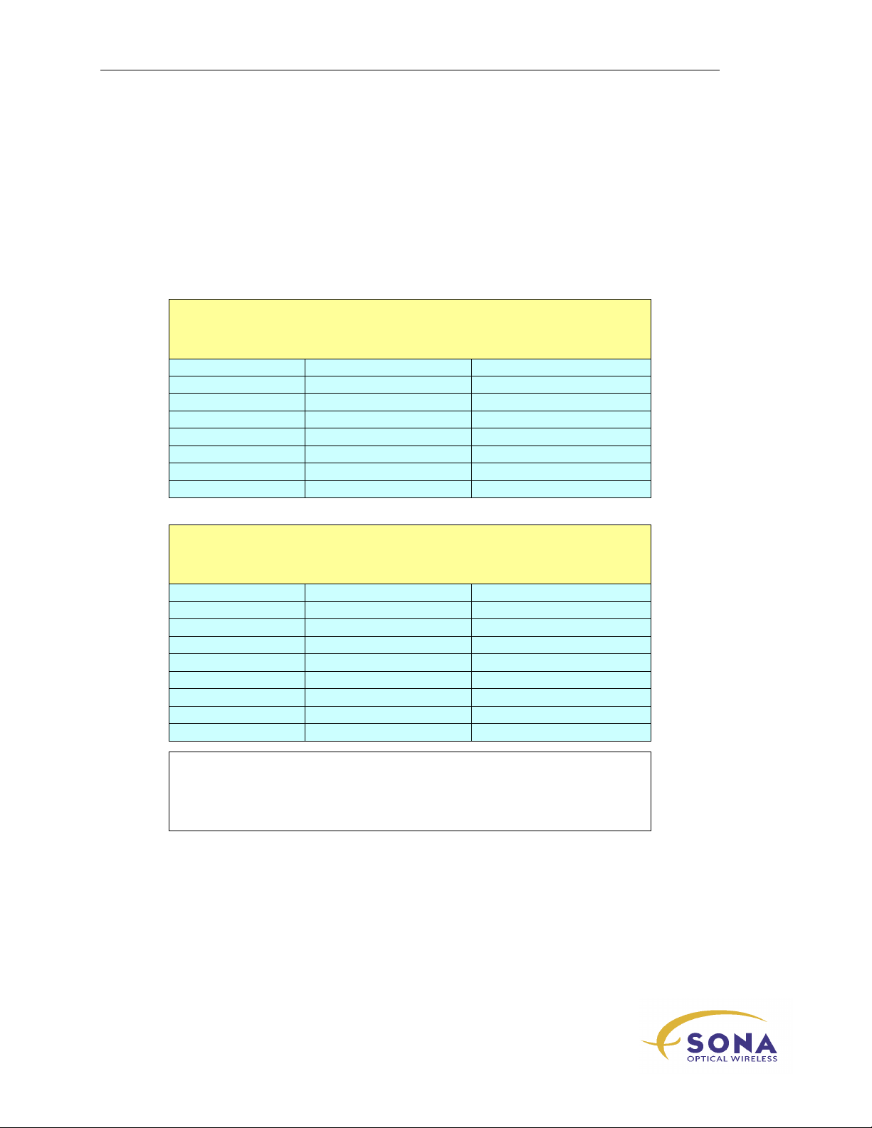
Aligning Your SONAbeam Terminals
2.4 V
Received Signal Strength Guide
The following tables are offered to assist you in gauging when your terminal alignment is
optimal. This information is to be used ONLY as a guide, as daily conditions at your
installation site can affect the received power levels for your particular link. Still, the
information from this table can prove helpful when aligning your SONAbeam link.
155-E:
SONAbeam 155-E Series Terminals @ Laser Pwr Index = 14
Range (meters) STC display (µwatts) Voltmeter
100 900 (Power Index = 6) 4.0 V
150 650 (Power Index = 8) 3.0 V
250 900 4.0 V
500 220 1.0 V
750 90 410 mV
1000 50 230 mV
1500 20 100 mV
2000 10 60 mV
‘Typical’ Clear-Air Receive Signal Strength*
1250-E:
SONAbeam 1250-E Series Terminals @ Laser Pwr Index = 14
Range (meters) STC display (µwatts) Voltmeter
200 330 (Power Index = 8) 5.7 V (Power Index = 8)
300 360 (Power Index = 12) 6.1 V (Power Index = 12)
350 420 7.0 V
400 320 5.6 V
500 200 4.0 V
750 90
1000 50 1.8 V
1200 35 1.3 V
1500 20 0.8 V
*
Clear-weather conditions, with optimal alignment
*
No windows or partial beam obstructions
*
Lasers operated at full-power (unless otherwise specified)
*
Results can vary ±20% (±1 dB) due to smog, haze, and manufacturing variations
‘Typical’ Clear-Air Receive Signal Strength*
NAbeam E-Series Installation Manual
68
wireless at the speed of light …………….
Page 79
Aligning Your SONAbeam Terminals
NOTE…
When properly aligned, both terminals will report similar Rx Power to within
3dB. So for one terminal to report 100uW, while the other reports 200uW is still
within this 3dB margin.
Stage 4 – Locking your Final Alignment
When you have tuned each SONAbeam terminal for optimal signal strength, lock the
azimuth and elevation tuning:
1.
Carefully screw in each locking screw until they make contact with the steering
block.
2.
GENTLY tighten each locking screw against the steering block; noting any
variation in your terminal’s receive signal strength.
3.
If your measured signal strength is affected by the alignment locking operation,
you may need to tweak opposing tuning screws to obtain the desired alignment.
NOTE…
When you have completed the Fine Tuning stage, both SONAbeams should report
approximately the same Receive Signal Strength…
To test mount stability try pushing on the mounting mast and the SONAbeam in
various places so that the signal strength reduces by 25%. After releasing the
force, the signal should return to approximately its original value.
Ask your fSONA representative for a copy of APPNOTE-95-0227, which
documents a simple procedure that you can perform to quantify the stability of
your terminal mount.
wireless at the speed of light …………….
-Series Installation Manual
69
Page 80
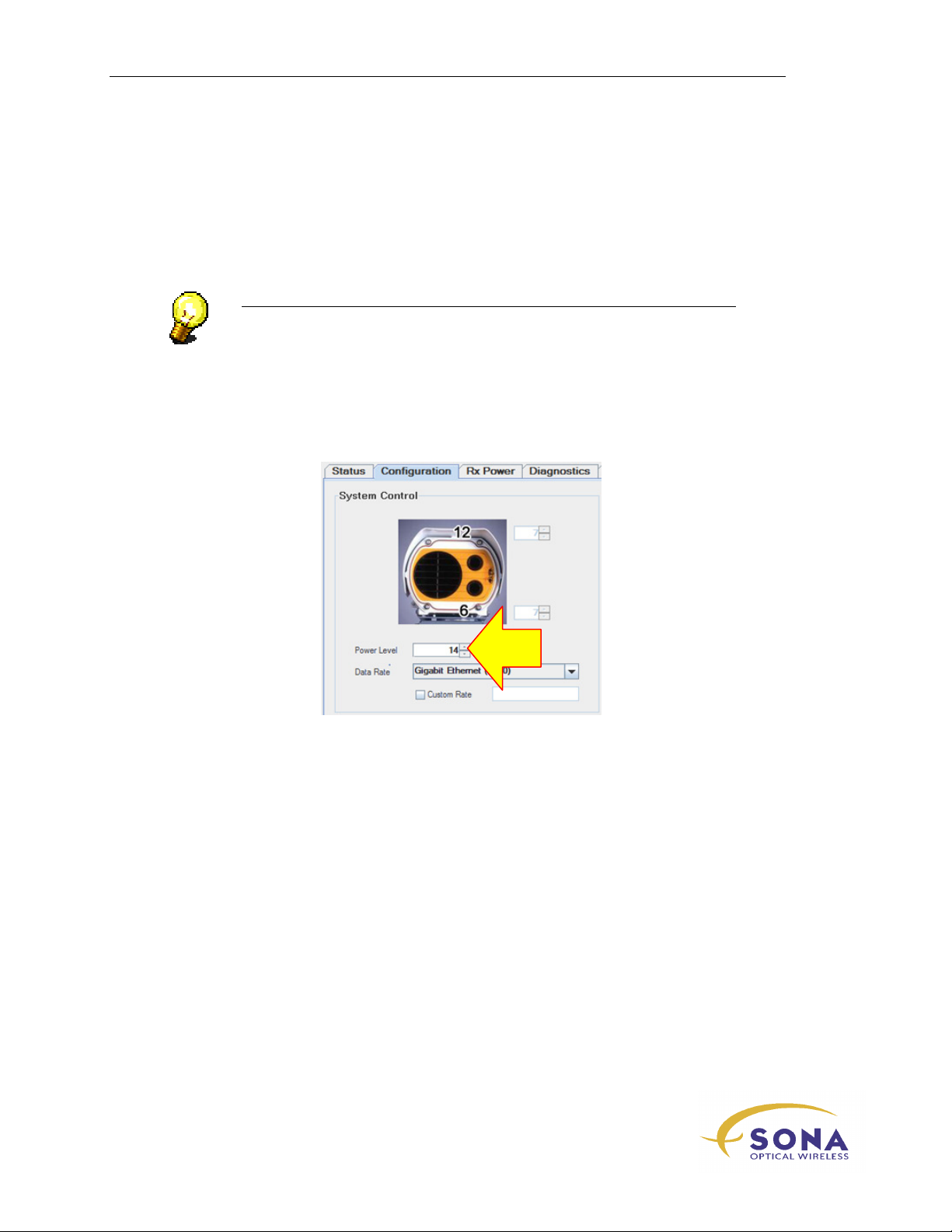
Aligning Your SONAbeam Terminals
Completing the Installation
Completing your installation entails any or all of the following:
1 -
Removing the alignment telescopes.
NOTE…
Take proper care of your Alignment Tool Kits and they will serve you well
for many installations…
2 -
Setup your terminals for maximum power:
If your terminals are both set to maximum
needs be done.
If you have reduced your terminal’s
during alignment, use your STC to increase the terminal’s
either the maximum (14) OR to produce the highest allowable Rx Power reading
according to the following:
Terminal Type Max Allowable Rx Power
155-E 1200µW
Power Level
Power Level
(14), nothing further
to avoid receiver saturation
Power Level
to
1250-E 1500µW
3 -
Removing any temporary connections to the SONAbeams & restoring any
temporary disconnections.
4 -
CAREFULLY replacing the Customer Interface Area cover.
NAbeam E-Series Installation Manual
70
wireless at the speed of light …………….
Page 81
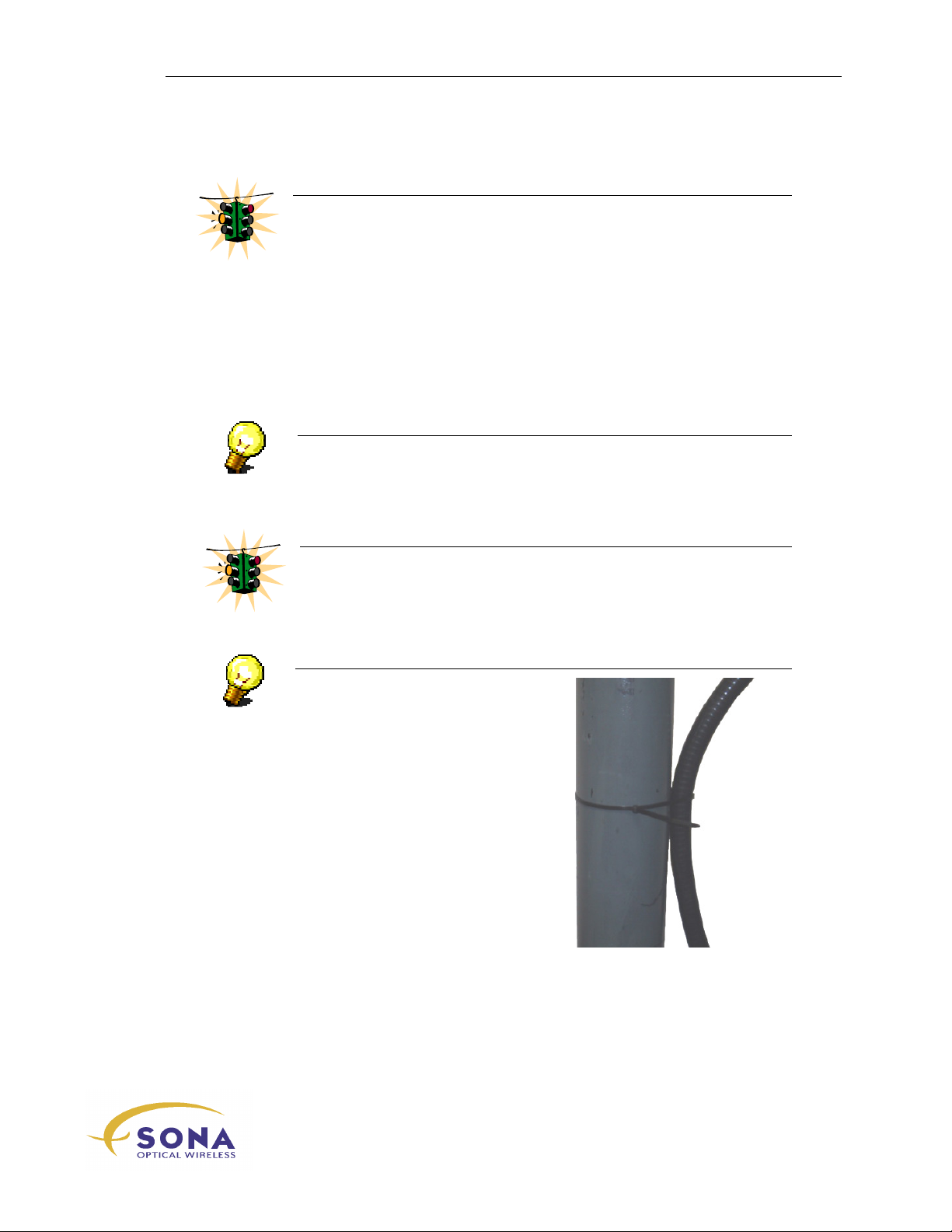
Aligning Your SONAbeam Terminals
WARNING!
When replacing the cover to the Customer Interface Area, ensure the cover’s
gasket is properly seated in the terminal’s housing and be careful not to
pinch any of your interfacing cabling!
Sequentially tighten each of the cover screws one turn at a time to ensure the
cover sits true to the housing…
5 -
Replacing the cover to your (customer-supplied) Customer Interface Box.
6 -
Executing an appropriate acceptance test.
NOTE…
It is best to include your Network Management personnel in devising and
implementing a realistic deployment plan suited to the specific application
of your SONAbeam link…
WARNING!
Contact the appropriate Network Management personnel prior to initiating
the live deployment of the SONAbeam link…
NOTE…
Where applicable, use the large Cable
Ties – included in your Installation Kit
– to secure your Conduit to the
mounting pole, as illustrated here:
-Series Installation Manual
wireless at the speed of light …………….
71
Page 82

Aligning Your SONAbeam Terminals
NAbeam E-Series Installation Manual
72
wireless at the speed of light …………….
Page 83
Deploying Your SONAbeam Link
Deploying Your
SONAbeam Link
After installing and aligning your SONAbeam terminals, all that remains is the actual
deployment of your optical SONAbeam link. After removing the test equipment attached
to each SONAbeam for its alignment and replacing the covers to the Customer Interface
Compartment and any applicable Customer Interface Boxes, this final operation can be
simply described as plug ‘n play, wherein the fiber optic connections to your
SONAbeams at both sides are terminated to their appropriate network ports and data
exchanges across your link are conducted and verified.
WARNING!
Contact the appropriate Network Management personnel prior to initiating the
live deployment of the SONAbeam link…
The actual process by which this operation is conducted will depend upon exactly how
you apply your SONAbeam link and what sorts of networking apparatus you deploy with
your link.
NOTE…
It is best to include your Network Management personnel in devising and
implementing a realistic deployment plan suited to the specific application of
your SONAbeam Link…
Putting SONAbeam Link to Work
Once you have completed and verified deployment of your SONAbeam Optical Wireless
Link, the system will offer you years of virtually maintenance-free service of transporting
data between your installation sites.
Furthermore, if you optionally implemented SNMP Agents for your SONAbeams, you
can use any SNMP compliant Network Management tools to remotely monitor your
SONAbeam terminals’ performance and/or automatically trap irregularities.
wireless at the speed of light …………….
73
-Series Installation Manual
Page 84

Deploying Your SONAbeam Link
NAbeam E-Series Installation Manual
74
wireless at the speed of light …………….
Page 85
System Problems
Syst
em Ready
User LED’s flash
STC will
Fiber Input
Terminal power
Check your power source.
Y
Y
Y
Y
N
N
N
N
Call fSONA Customer Service
Check your serial/USB connection.
Check your F/O Tx power & source.
A
System Problems
The following flowchart illustrates a basic problem-solving process for new SONAbeam
links.
switched ON
ON
LED flashes?
connect?
Check your power wiring.
Restart your STC software.
Check your STC’s Select Terminal choice.
Detect OK?
Check your terminal’s configured Data Rate.
Check your F/O source Data Rate.
Check for F/O Tx/Rx connections backwards.
wireless at the speed of light …………….
-Series Installation Manual
75
Page 86
System Problems
FSO Lock
Your Network
Y
Y
Y
N
N
N
Ready for
Check your OTHER terminal’s Laser Power.
Check for link obstructions.
Check your terminal’s
configured Data Rate.
Check for F/O Tx/Rx connections backwards.
Check your system’s configured Data Rate.
A
Rx Pwr OK?
OK?
Check your alignment.
Link OK?
Check your F/O power levels.
deployment
NAbeam E-Series Installation Manual
76
wireless at the speed of light …………….
Page 87

Customer Service Contact Information
Telephone: 604.273.6333
Fax: 604.278.6340
Web: www.fSONA.com
Email: [email protected]
 Loading...