

Page 1
Operating instructions
Transformer Switching Relay TSRL
FSM AG | Erich-Rieder-Straße 2 | D-79199 Kirchzarten | vertrieb@fsm.ag | www.fsm.ag
1/4
18.10.2018
1 | 8
Page 2

Table of contents
1 Introduction.. ..................................................................................................................................................................... 3
1.1 Notes on operating instructions ..............................................................................................................................................3
1.2 Explanation of icons and symbols ...........................................................................................................................................3
1.3 Intended use and foreseeable misuse ....................................................................................................................................3
1.4 Functions. ......................................................................................................................................................................................3
1.4.1 Smooth switching procedure ....................................................................................................................................................3
1.4.2 Half-wave failure recognition .................................................................................................................................................. 4
1.4.3 Dimming (Special version) ....................................................................................................................................................... 4
2 Notes for your safety.. ..................................................................................................................................................... 4
3 Set up and installation ....................................................................................................................................................4
3.1 Scope of delivery ........................................................................................................................................................................ 4
3.2 Connections and operating elements .................................................................................................................................... 5
3.3 Installation ................................................................................................................................................................................... 5
3.4 Set up ............................................................................................................................................................................................ 5
4 Operation ........................................................................................................................................................................... 5
4.1 Potentiometer (TP1) ................................................................................................................................................................... 5
4.2 Potentiometer setting ............................................................................................................................................................... 6
4.3 Adjustments using a packet core transformer as an example ........................................................................................ 6
5 Maintenance and service ................................................................................................................................................ 6
6 Troubleshooting guide ..................................................................................................................................................... 6
7 Accessories and spare parts .......................................................................................................................................... 7
7.1 Accessories ................................................................................................................................................................................... 7
7.2 Spare parts ...................................................................................................................................................................................7
8 Technical data ................................................................................................................................................................... 7
8.1 Dimensions....................................................................................................................................................................................7
8.2 Order code ................................................................................................................................................................................... 8
9 Disposal.. ............................................................................................................................................................................ 8
FSM AG | Erich-Rieder-Straße 2 | D-79199 Kirchzarten | vertrieb@fsm.ag | www.fsm.ag
2/4
18.10.2018
2 | 8
Page 3
1 Introduction
1.1 Notes on operating instructions
This operating manual was created to ensure perfect mounting, start-up, operation and maintenance, and must be read before
carrying out the following procedures. Keep this documentation handy and accessible for consultation by all users, whenever
needed. Pass on this documentation to any future users of the TSRL.
This manual contains descriptions of all necessary settings. Should any problems occur during commissioning or operation,
please do not make any unauthorised modications. By doing so, you could void your warranty. In such cases, please contact
us immediately:
FSM AG
Erich-Rieder-Straße 2
D-79199 Kirchzarten
+49 7661 9855 0
service@fsm.ag
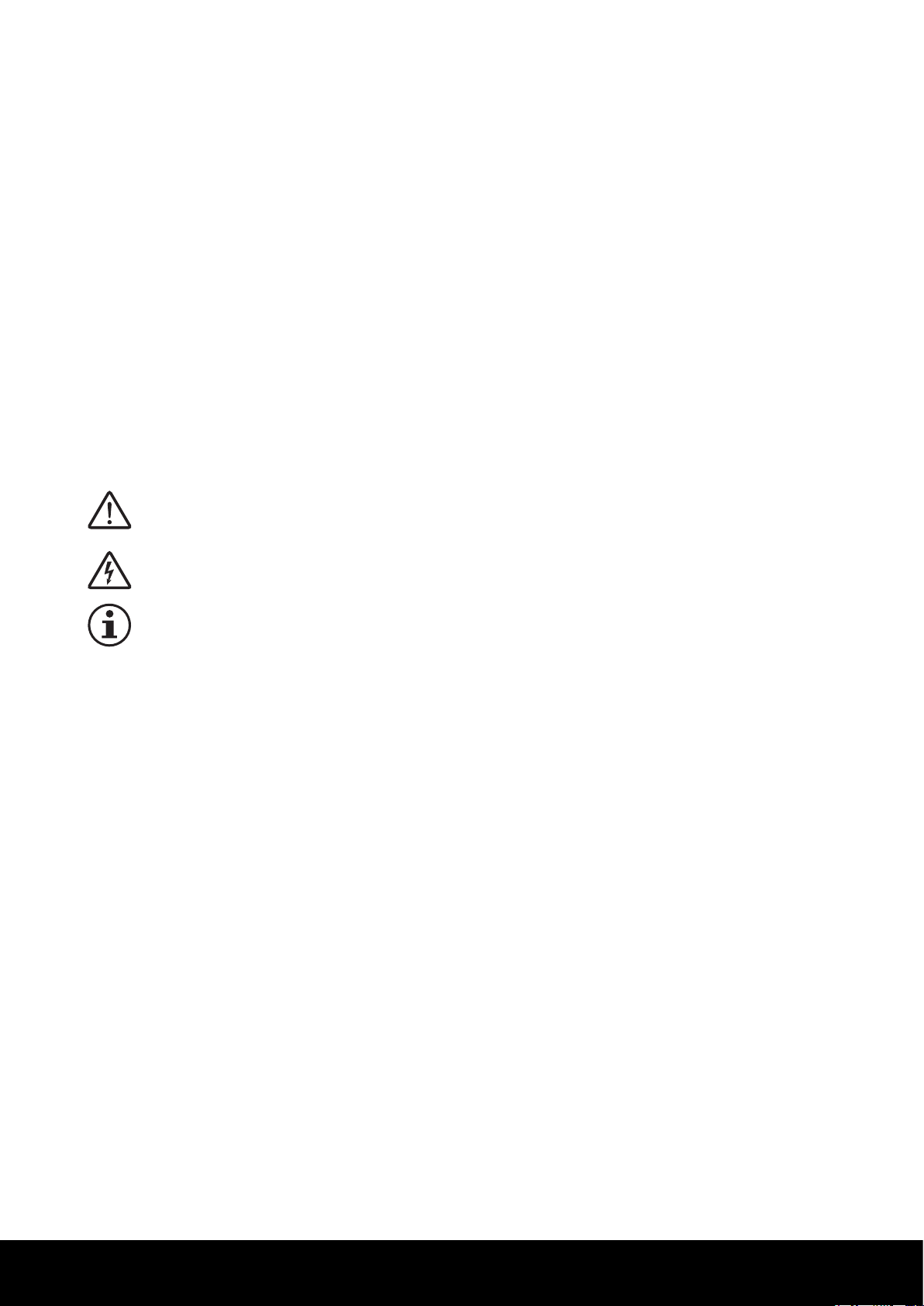
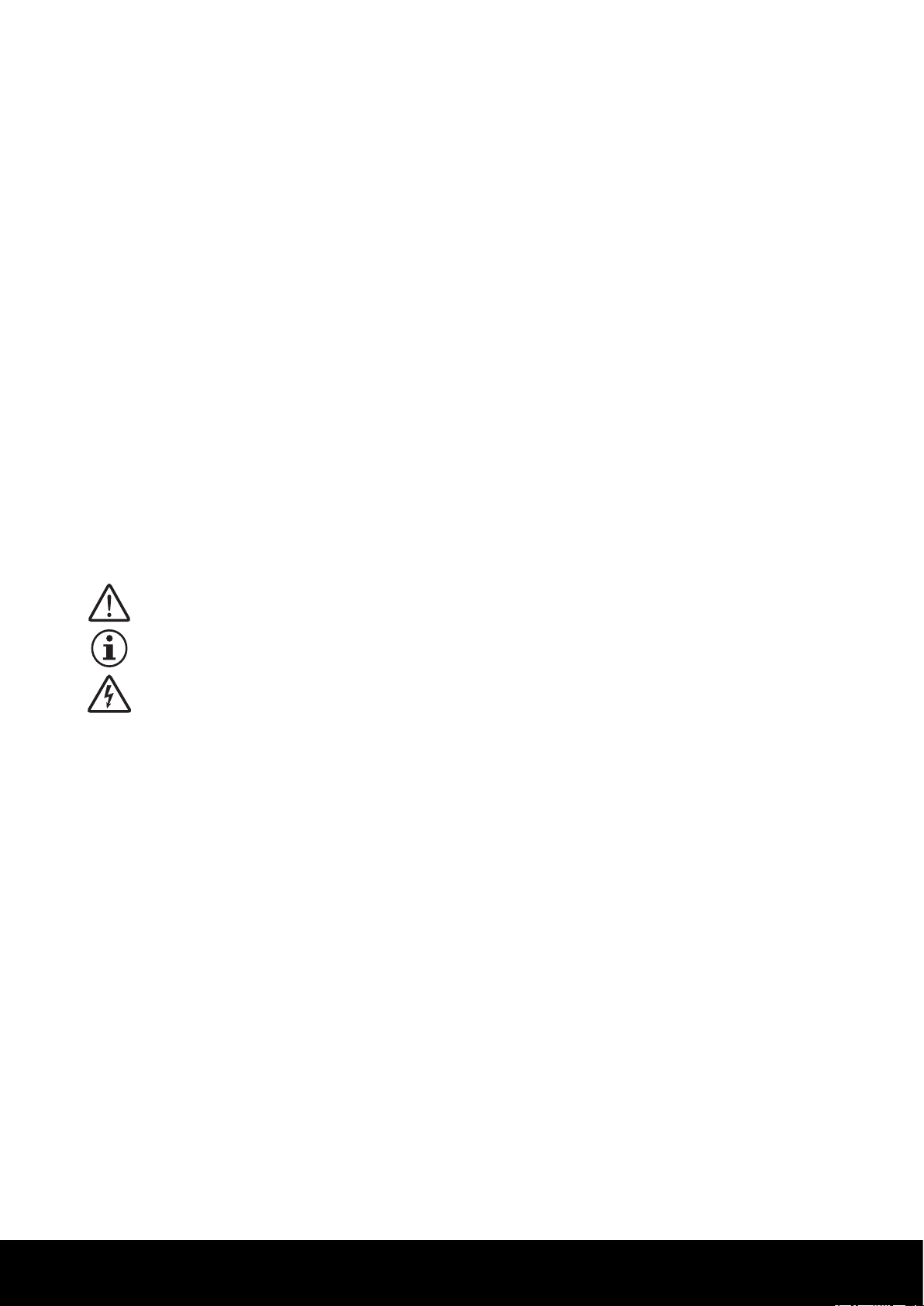
1.2 Explanation of icons and symbols
Danger
Indicates a hazard that could lead to personal injury.
Danger
Indicates a hazard through electric current that could lead to serious or fatal injuries, if disregarded.
Notice
Indicates important information that could lead to e.g. material damage, if disregarded.
1.3 Intended use and foreseeable misuse
The TSRL may only be used to switch transformers with or without load. The TSRL is commonly used for isolating-, control-,
lament- and traction transformers. The TSRL is solely intended for installation in a closed device. Outside mounting is not
allowed. Please ensure correct connection assignment (see chapter 3.2 Connections and operating elements). Please note the
technical datas on the type lable.
1.4 Functions
The TSRL is an electronic device for switching of transformers. It allows inrush-free switching of one or multiple single-phase
transformers with or without load. A smooth switching procedure completely prevents and not only reduces the inrush current. For this a unipolar phase stage is created with a thyristor. For complete switching on of the transformer, the thyristor is
bypassed by an external bypass relay. The TSRL has a control input which manages on and off switching.
The half-wave-failure recognition allows the TSRL to react to mains interruptions in compliance with DIN EN 61000-4-11. This
prevents power surges during the operation and is available as an option.
1.4.1 Smooth switching procedure
The TSRL premagnetises the transformer before complete switching using unipolar voltage impulses. The strength of the
premagnetisation is the same for all transformers, and its value should amount to on by turning point of the hysteresis curve.
The width of the required voltage impulses must be matched to the different transformer types, such as packet core transformers or toroidal core transformers. The potentiometer (TP1) in the TSRL is used for this purpose setting.
FSM AG | Erich-Rieder-Straße 2 | D-79199 Kirchzarten | vertrieb@fsm.ag | www.fsm.ag
3/4
18.10.2018
3 | 8
Page 4
1.4.2 Half-wave failure recognition
Line voltage distortions such as half-wave failures in accordance with DIN EN 61000-4-11 can result in saturation currents
larger than the inrush current in the transformer. The TSRL reacts to half-wave failures by immediately switching off before
saturation currents arise, and then the smooth switching procedure on operation is again resumed. In this manner a triggering
of the fuse can be avoided.
Half-wave-failure recognition with slow restart (available as an option):
At the end of a, faulty half-wave the TSRL switches off the transformer. The transformer is restarted using smooth switching
procedure.
Half-wave-failure recognition with fast restart (special version):
At the end of a half-wave with a failure the TSRL switches the transformer off. The transformer is restarted using the fast
restart-procedure. Depending on its remanence the transformer is restarted at the earliest timing possible. Delay is 40 ms
max. after voltage recovery.
1.4.3 Dimming (Special version)
The TSRL can also be used in the smooth switching of lter capacitor elements such as frequency converters used in mains
input circuits. Large lter capacitors following a transformer can also be switched smoothly. In this case the voltage impulses
are continuously increased up to the potentiometer (TP1) set values before complete switching.
2 Notes for your safety
Danger
The guidelines contained in this book need to be read and followed to ensure safe operation. To avoid injury and
material damage, the device must be installed and operated under conditions and within limits as listed under
“Technical Data”.
The device may only be installed or operated by trained and experienced personnel. Maintenance and servicing of
this device must be carried out by authorized technicians familiar with risks and warranty conditions involved.
For standard units, do not apply external voltage at control input (terminal S1/S2). Terminal S1 and S2 are
connected to mains potential and need to be overrided for power up. Therefore, the connected switching contact
or optocoupler-transistor needs to be potential-free and boast a test voltage of min. 2,5 kV.
If a wire link is tted between terminal S1 and S2 instead, it needs to be appropriately isolated.
When switching the TSRL via the control input and without mains switch, there is no potential separation as a
thyristor with an additional RC element is connected between terminal 1 and 2. Therefore, the TSRL must be
disconnected from the mains while working on the connected transformer or at the load on the secondary side.
3 Set up and installation
3.1 Scope of delivery
The scope of supply includes one TSRL and the corresponding quick reference guide.
FSM AG | Erich-Rieder-Straße 2 | D-79199 Kirchzarten | vertrieb@fsm.ag | www.fsm.ag
4/4
18.10.2018
4 | 8
Page 5

3.2 Connections and operating elements
ccw
cw
P
The TSRL must be connected according to the connection diagram and the version of the control input used.
Transformer
Type
Control input
Control input for normally
open contact (Standard)
Burden
Mains connection
Control input for
Control voltage (Option)
Control voltage
3.3 Installation
Depending on the type of TSRL the following installation methods exist (see also chapter 8.1):
> Circuit board for installation: The TSRL can be installed using three mounting holes.
> Housing for wall mounting: The TSRL can be installed using two mounting holes on the housing.
> Housing with standard rail holder: The TSRL can be installed on any 35 mm standard rail holder in accordance with DIN EN 60715 .
3.4 Set up
> Make sure the voltage of your version of the TSRL and the mains voltage are compatible. Please also consider compatibility
of the transformer’s primary current with the TSRL’s load current.
> Please ensure compatibility of the control input with the intended circuit. Please note that the control input of the TSRL’s
standard version is connected to mains potential.
> Adjust the potentiometer (TP1) to the utilized type of transformer.
> When using the control input please switch control input to „Off“ before applying main voltage.
4 Operation
4.1 Potentiometer (TP1)
View on device for setting of the potentiometer:
R
For orientation please note that position P matches 12:30 o’ clock:
> Toroidal transformers. : Use the setting R
> Packet-core-transformers: Use the setting P (factory settings). The correct setting for this type of transformers (P) can vary
between „10 and 2 o’clock“.
> C-core transformers: Potentiometer setting between „P“ and „R“.
> Switching power supply: Setting potentiometer at 4:30 o‘clock.
FSM AG | Erich-Rieder-Straße 2 | D-79199 Kirchzarten | vertrieb@fsm.ag | www.fsm.ag
5/4
18.10.2018
5 | 8
Page 6

4.2 Potentiometer setting
An analogue instrument for AC current in series with the TSRL - (i.e. parallel to opened fusing device) indicates whether or
not switching occurs with surge currents. If current peaks do not arise either during or at the end of premagnetisation, then
the TSRL is correctly set to the transformer (the pointer on the current meter stands still). Optimum setting: See instructions
below.
4.3 Adjustments using a packet core transformer as an example
Incorrect setting Correct setting Incorrect setting
The premagnetisation is too weak.
The Potentiometer is too far to the
left. The negative magnetisingcurrent pulses are too small. A large
positive inrush current is visible after
premagnetising.
The premagnetisation is just strong
enough. The potentiometer setting is
correct. Inrush current is not present.
The premagnetisation is too strong.
The potentiometer is too far to the
right. Large negative magnetisation
currrent peaks are visible.
5 Maintenance and service
For the TSRL no special maintenance is needed. It is recommended to check and ,if necessary, retighten the connection terminal regularly. Use dry compressed air to remove dust deposits. For that make sure mains voltage is turned off.
6 Troubleshooting guide
If malfunctions occur while installation or operation of the device, the following list can support you to identify and repair those. If your defect is not listed, please contact FSM AG at your earliest convenience or send in your device with an informative
description of the malfunction.
Error indication Error description Error rectication
No mains voltage on device or
transformer.
The fuse trips
A malfunction of the TSRL itself can only be remedied by repair or replacement of the device. If the error can not be remedied please contact our service team: Service@fsm.ag
The TSRL does not switch on.
> Please check mains voltage
(see chapter 3.4)
> Please check fuses (see chapter
3.2)
> Please check connection of control
inputs (see technical data and
chapter 3.4)
> Please check if setting of the po-
tentiometer (TP1) matches type of
transformer (see chapter 4.1)
FSM AG | Erich-Rieder-Straße 2 | D-79199 Kirchzarten | vertrieb@fsm.ag | www.fsm.ag
6/4
18.10.2018
6 | 8
Page 7

7 Accessories and spare parts
45,5 11
89,5
99
D4,5
35
107
88
45,5 11
77,5
99
7.1 Accessories
There are no accessories.
7.2 Spare parts
There are no spare parts available. The TSRL can only be completely replaced or repaired.
8 Technical data
Technical data can be found in the corresponding data sheet, which is available at www.fsm.ag, or can be downloaded
using the QR code below.
8.1 Dimensions
All dimensions in mm
44,25
D3,2
ø
63,5
77,5
61
85
82
3
89,5
D4,5
ø
107
88
35
2,5
FSM AG | Erich-Rieder-Straße 2 | D-79199 Kirchzarten | vertrieb@fsm.ag | www.fsm.ag
7/4
18.10.2018
7 | 8
Page 8

8.2 Order Code
TSRL
Netzspannung
1= 110V
3= 32 A
2= 230 V
4= 400 V
5= 500V
9= Sonderspannungen
Halbwellenausfall
0= ohne Halbwellenausfall-Erkennung
1= mit Halbwellenausfall-Erkennung
1= Steuereingang für Schließerkontakt
Steuereingang
2= Steuereingang für Steuerspannung
Nennstrom
2= 16 A
Externes Potentiometer
0= internes Poetentiometer
1= externes Potentiometer
Sonderversions-Nummer
(wird vom Hersteller vergeben)
00= Standardversion
Bauform
1= Platine zum Einbau
2= Gehäuse für Wandmontage
3= Gehäuse für Normschienenhalter
TSRL
9 Disposal
Special version number
(supplied from the manufacturer)
00 = Standard version
Type
1 = Circuit board for installation
2 = Housing for wall mounting
3 = Housing with standard rail holder
Half-wave failure recognition
0 = without half-wave failure recognition
1 =with half-wave failure recognition
External Potentiometer
0 = internal potentiometer
1 = external potentiometer
Control input
1 = Control input for normally open contact
2 = Control input for control voltage
Rated current
2 = 16 A
3 = 32 A
Main voltage
1 = 110 V
2= 230 V
4 = 400 V
5 = 500 V
9 = Special voltage
FSM AG | Erich-Rieder-Straße 2 | D-79199 Kirchzarten | vertrieb@fsm.ag | www.fsm.ag
This device may not be disposed of with general household garbage. Electronic devices are subject to
guidelines for electronic equipment and need to be disposed at your local collection point.
WEEE-Reg.-Nr. DE 47299690
Notice
Incorrect disposal can lead to environmental hazards.
Equipment components and packaging materials from the TSRL must be disposed of in an environmentally sound
manner in accordance with the local regulations on waste treatment and disposal.
8/4
18.10.2018
8 | 8
 Loading...