

Page 1
FSM AG | Erich-Rieder-Straße 2 | D-79199 Kirchzarten | vertrieb@fsm.ag | www.fsm.ag
13.09.2018
1 | 4
> Operating instructions
Transformator switching relay | Type TSRD
With TSRD the both three-phase transformers and combinations of three individual single-phase transformers can be switched-on in a three-phase network without inrush currents arising. The required application is selected using DIP-switches.
Note in safety
Potential separation does not occur during switching of the TSRD as additional RC elements are connected between the
input and the output thyristor clips. To bypass the thyristors, a bypass contactor must be connected in parallel to the TSRD.
General
The required application is selected using DIP-switches. In the case of applications N and L the transformer core type must
be selected at TP1 (transformer type) The TSRD has a Message Display Output (Message 1). Depending on the DIP-switch
selections four different conditions can be displayed. The DIP-switches should be set only when the power is off.
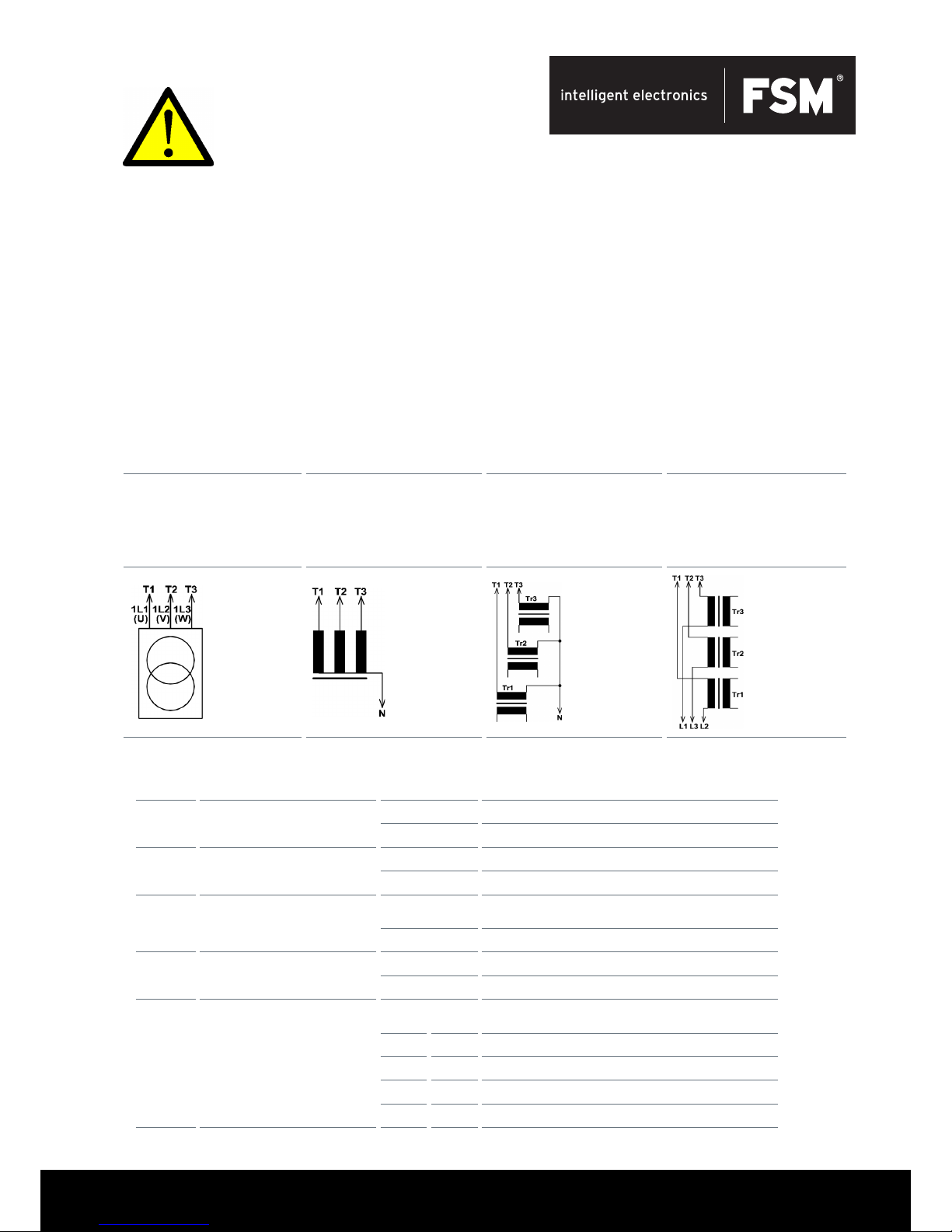
Applications
Application D Application S Application N Application L
Three-phase transformer, prima
-
ry side delta or star cong.
without N (neutral) (arbitrarily
loading). Winding direction
important for transformer
connection.
Three-phase transformer, prima-
ry side star cong. with N
(neutral) (arbitrarily loading).
Winding direction important for
transformer connection.
3 single-phase transformers having the same core (arbitrarily
loading). The core type is set at
TP1.
3 single-phase transformers
having the same core (arbitrarily
loading). The core type is set
at TP1.
DIP-Switches
No. Function Position
1 Error handling
OFF No automatic restart
ON Automatic restart after an error
2 Rotation direction recognition
OFF Switched-on for clockwise phase-sequence
ON Switched-on for clockwise and anticlockwise phase-sequence
3
Control input 1
(Remote-on input)
OFF Control input enabled for external control signal
ON Switched-on without external control signal
4 Control input 2
OFF Control input enabled for additional external control signal
ON Switched-on without external control signal
5/6 Message display 1
5 6 Function Message Display 1:
OFF OFF Fully-on message
ON OFF OK message
OFF ON Error message
ON ON Bypass contactor control
Note: Installation and commissioning
have to be undertaken by a qualied
person or a person under the supervision of a specialist.
Page 2
FSM AG | Erich-Rieder-Straße 2 | D-79199 Kirchzarten | vertrieb@fsm.ag | www.fsm.ag
13.09.2018
2 | 4
7/8 Applications
7 8 Application type:
OFF OFF D, Three-phase transformer, delta or star cong. without MP
ON OFF S, Three-phase transformer, star conguration with MP
OFF ON N, 3 Single phase transformer between phase and N
ON ON L, 3 Single phase transformer between two phases
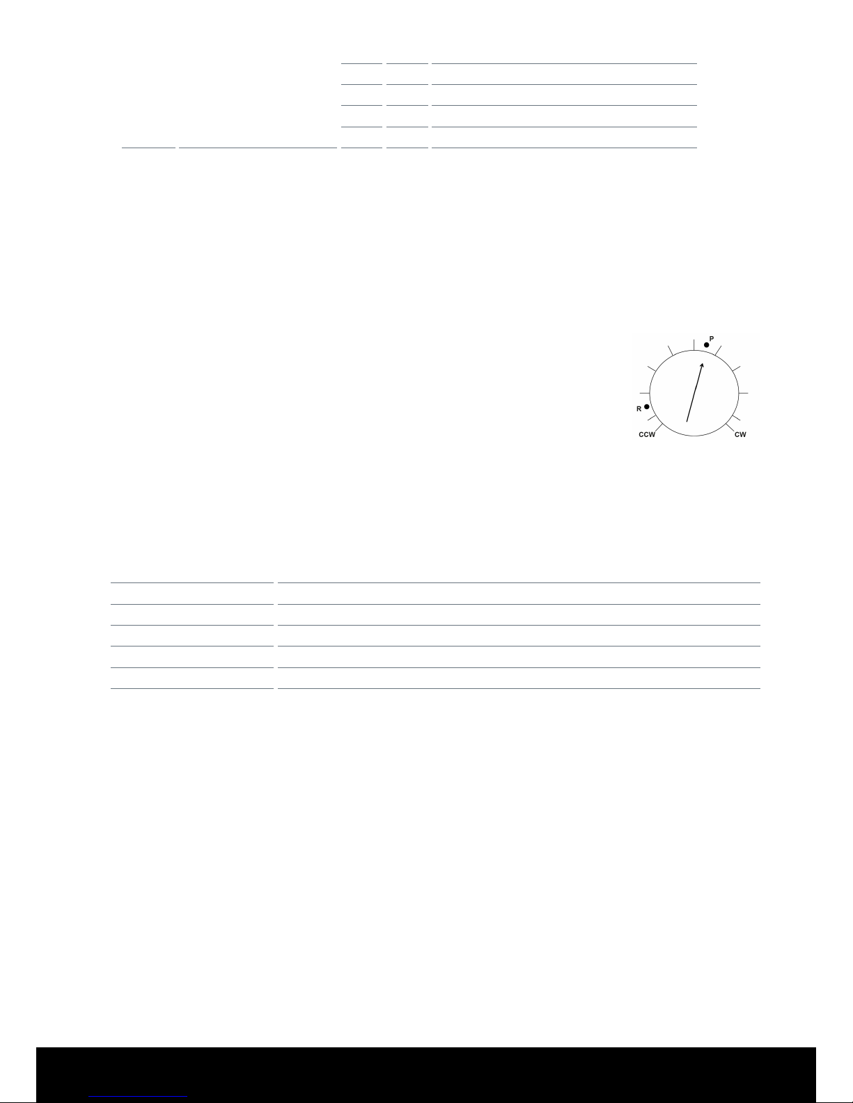
Setting premagnetisation on the trimming potentiometer depending on transformer type
On the trimmer potentiometer TP1 the transformer core type of the single-phase transformer being used
for application N or L must be set. For applications D and S the trimmer function does not apply.
> Toroidal core transformers set to position R
> Coil form (shell) transformers (stack-core transformers): Set to position P (factory setting)
> The correct position for stack-core transformers (P) can vary between the „10- and 2 o’clock „ position.
> Strip-wound cut core transformers: Potentiometer setting between the „P“ and „R“ settings
Messages
The LED „Message Display 1“ (yellow) is illuminated, when the relay contact between the
terminals 23 and 24 is closed. The Message Display1 can be applied for various functions.
Fully-On message: The relay contact is closed, as soon as the connected transformer has been
fully switched-on by the TSRD when the premagnetisation (remnance setting) is completed.
OK message: The relay contact is closed after power is supplied to the TSRD and initialisation is
complete . On malfunction the contact is opened.
Error message: On malfunction the contact is closed.
Bypass contactor: The relay contact is used to control a bypass contactor, used to bridge the control elements.
OK-LED
The LED OK (green) is illuminated when the TSRD is in the ‘OK’ status. Malfunctions are indicated by different ashing
rates.
Flashing rate Interference
continuous OK state
10 Hz A remote-on signal has been applied, and no automatic resetting after malfunction (DIP1=Off)
5 Hz Three-phase network is counter-clockwise, and switching-on only for clockwise phasesequence (DIP2=Off)
1 Hz The supply voltage is outside the limiting voltage values (-20/+15% of U
rated)
10 Hz Internal error
Additional information
> Bypass-contactor: To protect the safety coil it is recommended to connect an RC-element parallel to the coil.
> Fuse: The need in the data sheet under „Current“ dened limits are met. If this is not possible, the TSRD should accor-
ding to the circuit example (see last page) are connected.
Page 3

FSM AG | Erich-Rieder-Straße 2 | D-79199 Kirchzarten | vertrieb@fsm.ag | www.fsm.ag
13.09.2018
3 | 4
Application Description
Application-Description of the coil inter-connection at 3 phase transformers for a particular vector group. For the correct
function of the Transformer Switching Relay TSRD, to switch on 3 phase transformes without inrush current peaks, the
transformer coil endings must be connected in the right manner to the TSRD and must also be inter-connected in the right
manner for the particular vector group.
What means the begin of the coil,
marked with a dot, and the denition
of the direction of the bring up for
the windings
Usual manner of the inter connection from the coils
for a Delta Star vector group and the connections
from the transformer clamps L1, L2, L3 to the clamps
L1, L2, L3, from the TSRD, when windings are put on
in a clockwise manner onto the Iron core, if looking to
the top of the coil and to the winding start, for a DYN5
vector group transformer.
The dot marks the begin, start, of the windings on the
view from top for the bringing up of the windings.
Sometime it happens, that the coils are produced in a count clock wise winding direction onto the core, like showed in
the bottom left. The numbering of the clamps of the transformer must than be changed like showed in the picture in the
bottom right, L3 left and L1 right and similar connected L3 to L3 and L1 to L1 of the TSRD, for softstart the transformer
without inrush current peaks, via the TSRD and only with the value of the no load current at a delta vector group of the
primary side. (The interconnection of the coils for the Delta vector group is then corresponding to the connections showed
in the picture on the top rigt, L1 left and L3 right.)
View to top of the iron core, if the
coils are produced in a count clockwise manner.
View to top of the iron core, if the coils are produced
in a count clockwise manner.
Thats not usual but it can happen. Connections for the
Delta vector group in the usual manner, however with
exchanged connections L1 and L3, if the windings are
bring up count clock wise..
Disclaimer:
Improper installation and commissioning can result in property
damage and endanger people in a row. FSM AG accepts no responsibility or liability for loss, damage or expense resulting from
improper installation, commissioning improper operation, and
improper use and maintenance.
Fuse with F1:
The need in the data sheet (Page 3) under
„Current“ dened limits are met. If this is not
possible, the TSRD should according to the circuit
example (see last page) are connected.
Terminal connection diagram
Page 4

FSM AG | Erich-Rieder-Straße 2 | D-79199 Kirchzarten | vertrieb@fsm.ag | www.fsm.ag
13.09.2018
4 | 4
Circuit Example
TSRD is separately fused with fast blowing types to protect the tyristors inside the TSRD, if the connection cables to and
from the TSRD are small and long enough. This is recommended if the output of the transformer can have a short circuit,
while start procdure. The fuses directly in front of the TSRD are selctive to the fuses on the input of the schematic drawing.
The transformer have to be softstarted in a no-load or low-load state. During the softstart only the no load current value is
owing (at the delta vector group). Then can be softstarted a transformer with a higher value of current like TSRD has. The
TSRD only start the transformer then he activates the bypass contactor. This contactor is going in a self holding mode and
switches the TSRD off with his opener contacts. If any overload or Power line failures occures, the TSRD is not inuenced
with overcurrents or wrong softstart repeating attempts, because he is switched off as long as the Bypasscontactor is
closed.
> Power line lters must be placed in front of the TSRD. In the other way the
phase angle cutting softstart procedure leads to high current peaks and can
disturb the power line or can destruct the thyristors. If capacitive AC- loads
are connected behind the transformer, a additional separation contactor must
switch on this loads after the softstart procedure. Also if other transformers
are connected on the output of the softstarted transformer must these be
separated with a additional separation contactor from the Softstart transformers output, while he is in Softstart procedure. If high valued capacitors are
placed after rectiers behind the softstarted transformer, a special softstart
procedure can also soft start these capacitors. Look to the special order
numbers.
 Loading...