

Page 1

Colibri Grande PRO
User's manual
09.05.2011
Page 2

OVERVIEW
- 1 -
FEATURES
These DVR adapt H.264 video encoding for 4 or 8 channel inputs and G.723
audio encoding in order to store and replay.
● User friendly GUI and easy to install
● Various recording modes (Motion, sensor, scheduled recording)
● Mass storage hard disk backup through high-speed USB2.0 and eSATA.
● 4/8CH Composite Input through RJ45 or BNC connectors
● Mobile viewer for Smartphone
● Talk function for two way communication
● Triplex (Recording, Playback, Networking)
● Supplying DC12V power for camera
● Spot monitor for Public view support
● Web monitoring, Remote client SW, Remote setup
● Easy to control of the PTZ camera
● USB Mouse operation
● E-mail notification
● Abnormal shutdown detection and system auto recovery
● High quality and high performance
Page 3

Specifications – GRM Series
Best, High, Normal, Low / Timer, Motion, SensorQuality / Event type
Remote Controller / USB Mouse / NetworkControl Device
4 Input, 1 Output (Relay)8 Input, 2 Output (Relay)Input / OutputAlarm
DC 12V / 6A (72W)
0 ℃ ~ 45 ℃ / -15 ℃ ~ 55 ℃Operating / StorageTemperature
DC 12V / 8.33A (100W)Power
Pre/Post Event Recording, Summer time, Time SynchronizationOther Function
WEB monitoring, Remote client SW, Remote setupBrowser
Network
Timer, Motion, SensorSearch
380 X 348 X 60 (Excluded Stand)Dimension [mm] (WxHxD)
CIF (352X240 / 352X288)
120fps / 100fps
CIF (352X240 / 352X288)
240fps / 200fps
HALF D1 (704X240 / 704X288)
120fps / 100fps
HALF D1 (704X240 / 704X288)
240fps / 200fps
D1 (704X480 / 704X576)
120fps / 100fps
D1 (704X480 / 704X576)
120fps / 100fps
17” / SXGA17” / SXGA, 22” / WSXGA+Inch / ResolutionLCD
IN: 4CH / OUT: - / Built-inIN: 8CH / OUT: - / Built-inIn / Out / Speaker
7.0㎏ (15.4 lbs) / 9.3㎏ (20.5 lbs)7.2㎏ (15.9lbs) / 9.5㎏ (20.9lbs)Weight (Approx.) Net / Gross
TCP/IP, DHCP, DDNS / Two-way network audioProtocol / Function
RJ45, EthernetPhysical / Mac Layer
eSATA, USB interfaced storage, Network / Watermarking, AVI FormatDevice / FormatBackup
RS-485Signal typePTZ
Recording, Relay out, E-mail notification, Log file, Remote, Buzzer output, Pop Up Action
Sensor In, Motion detection, Video Loss, HDD EventSource
Event
44X30 Grid / 5 StepsResolution / SensitivityMotion detect
Write once / OverwritingMode
HDD(S-ATA) / No limitedType / Capacity
Storage
Abnormal Off detection, Auto recovery, Event log file, USB or Network F/W UpdateSystem Functions
NTSC: 30fps / 15fps / 10fps / 7fps / 5fps / 3fps / 2fps / 1fps
PAL: 25fps / 13fps / 8fps / 6fps / 4fps / 3fps / 2fps / 1fps
Frame Rate
Recording Resolution
H.264Video CODEC
NTSC / PAL Auto detection (Signal check)Format
Video Record
1,4,Sequence/ Graphic User Interface1,4,6,8,9,Sequence/ Graphic User InterfaceDivision / InterfaceScreen
Selectable Output: 4CH(RJ45)Selectable Output: 8CH(RJ45)Talk Output
Audio (Option)
1 CH Composite (BNC)Spot Out
Composite (BNC)Composite (BNC), S-Video (4pin Mini DIN)Monitor out
Video Out
4 X RJ-45, 4 X BNC8 X RJ-45, 8 X BNCNo. of ChannelVideo In
NTSC : 120fps, PAL : 100fpsNTSC : 240fps, PAL : 200fpsLive SpeedMain display
4Channel8ChannelSpecification
- 2 -
Page 4

Instructions
- 3 -
Thank you for buying GRM DVR series
This is the user manual for GRM DVR series. Before installing or operating this product,
please familiarize yourself with this user manual.
We retain the copyright on this manual. Therefore, with the exception of copying for
general use within the copyright law, copying and reprinting the user manual, either
partially or in its entirety, or translating it into another language without our prior written
approval.
Product warranty and limits of responsibility
Product warranty does not cover cases of accidents, negligence, alteration, misuses or
abuse. In addition, no warranty is offered for any attachments or parts not supplied by
the manufacturer.
We are not liable for any or all losses to the product incurred by your use of nonstandard product or violation of instructions mentioned in this manual.
The following cases are not covered by the warranty and payment is required for
repairs.
● Malfunction due to negligence in handling by the user
● Deliberate disassembly and replacement by the user
● Connection of an improper power supply
● Malfunction caused by natural disasters (fire, flood, etc.)
Warranty only refers to the warranty covering products that have been paid for.
After expiration of the warranty period, examination and repair will be provided for a
fee. Even during the warranty period, repair and examination of items outside the
preceding warranty scope will require a payment.
Before Start
This user manual provides Information for using DVR such as brief introduction part
names, functions, connection to other equipment, menu setup, and the like. You
have to keep in mind the following notices:
If you want to open the case of your system for checking problems,
please consult the expert from the shop where you bought the product.
Before operating the DVR
Page 5

Safety Precautions - Warnings
The symbol is intended alert to know in order to prevent
serious injury or death and Warnings are described below.
※ Before the installation
• Various experience and technical is needed for installation of this product.
All installation operations should be performed by the agency you purchased
this product from.
• Before connecting the AC power cord to the DC adaptor outlet, make sure the
voltage designation of the DC adaptor corresponds to the local electrical supply.
• Do not touch the power cord with wet hands and avoid install under humid
conditions or space
• Use only a properly grounded plug and receptacle.
An improper ground may cause electric shock or equipment damage.
• Make sure the POWER is OFF before installation
• Do not overload multiple wall outlets, extension cords or adaptors beyond their
capacity since this can result in fire or electric shock.
• Do not touch the power plug with wet hand and conductor materials etc.
Doing so can cause electrical shock and fire
• Never insert anything metallic or your hand into the open parts of this apparatus
Doing so many create a danger of electric shock.
• Make sure to plug the power cord in until it is firmly inserted. When pulling the
power cord, do not excessive force. Do not touch the power cord with wet hands.
- 4 -
Before operating the DVR
Page 6

Safety Precautions - Cautions
The symbol is intended alert to know in order to prevent
minor injury or product damages and cautions are
described below.
※ During installation
• Keep the required distances between the product and other objects (e.g. walls)
to ensure proper ventilation. Failing to do so may result in fire or a problem with
the product due to an increase in the internal temperature of the product.
• Do not install or place the product in an unstable location such as a shaky
self a slanted floor or a location exposed to vibration.
• Do not place this apparatus near or over a radiator or heat resistor or where it is
exposed to direct sunlight.
※ During use
• Do not move the product while it is operating.
• Do not connect the jacks or cables while your product is turned on.
• Do not allow children to hang onto the product.
• If this apparatus does not operate normally - in particular, if there are any
unusual sounds or smells coming from it - unplug it immediately and contact
an authorized dealer or service center.
• When you install two batteries of remote controller make sure to match the
polarity of the batteries.
• Product design and specifications may be changed without notice in order to
enhance product performance.
• The slots and openings in the cabinet are provided for necessary ventilation to
ensure reliable operation of this apparatus and to protect it from overheating,
these slots and openings must never be blocked or covered.
• This apparatus use batteries require you to dispose of batteries properly for
disposal or recycling information. Use the same type battery.
- 5 -
Before operating the DVR
Page 7

- 6 -
FCC Compliance Statement
Caution : Any changes or modifications in construction of this device which
are net expressly approved by the party responsible for compliance could
void the user’s authority to operate the equipment.
This device complies with part 15 of the FCC Rules. Operation is subject to the following two
conditions: (1) This device may not cause harmful interference, and (2) This device must accept any
interference received, including interference that may cause undesired operation.
Note : This equipment has been tested and found to comply with the limits for a Class A digital
device, pursuant to part 15 of the FCC Rules. These limits are designed to provide reasonable
protection against harmful interference when the equipment is operated in a commercial environment.
This equipment generates, uses, and can radiate radio frequency energy and, if not installed and
used in accordance with the instruction manual, may cause harmful interference to radio
communications. Operation of this equipment in a residential area is likely to cause harmful
interference in which case the user will be required to correct the interference at his own expense.
Before operating the DVR
Page 8

INDEX
- 7 -
OVERVIEW
Before Operating the DVR
INDEX
Package Contents
Optional accessories
Remote Controller
Product exterior
Connecting to other devices
RJ-45 Port Layout
Installation the HDD
Getting Started
Live Mode
Setting the Menu
MAIN MENU
SYSTEM
1 FEATURES
2 Specifications
3 Instructions
4 Safety Precautions - Warnings
5 Safety Precautions - Cautions
6 FCC Compliance Statement
7
9 Package Contents
10 Optional Cable Adapter
11 Parts name and Functions
12 8 Channel - Front, Back and Bottom
13 4 Channel - Front, Back, and Bottom
14 Exterior Names and Functions
15 Connecting to the 8 channel
16 Connecting to the 4 channel
17 Connecting to the RS-485, Sensor
18 Cam Input Pin Assignment
19
20 Starting the System
Power off the System
Screen ON/OFF
21 Started Login
22 Icons on the Live Screen
23 Main Menu Icons
24 Menu Explanation
25 Setting the System Name
26 Password
Page 9

INDEX
- 8 -
SYSTEM
RECORD
CAMERA
REPLAY
EVENT LOG
DISPLAY
SOUND
BACKUP
NETWORK
HDD
PTZ CONTROL
HELP
REMOTE CONTROL
27 Setting System ID
27 System configuration
28 Time / Date Change
29 Firmware Update
29 Hardware / IP / MAC Address etc
30 Setting the Record
31 Setting the event
32 Motion Detection
34 Recording Schedule
36 Camera Setting
37 PTZ Camera Setting
38 Search
39 Event Search
39 Replay
40 Event Log
41 Display
42 Sound
43 Backup
44 Network Configuration
45 DDNS
46 E-Mail notification
47 Setting HDD
48 Controlling a PTZ device
49 HELP
50 Installing the SMART VIEWER
51 DVR LIST SETUP
57 What is Web Viewer
58 Connecting the Smartphone
Page 10
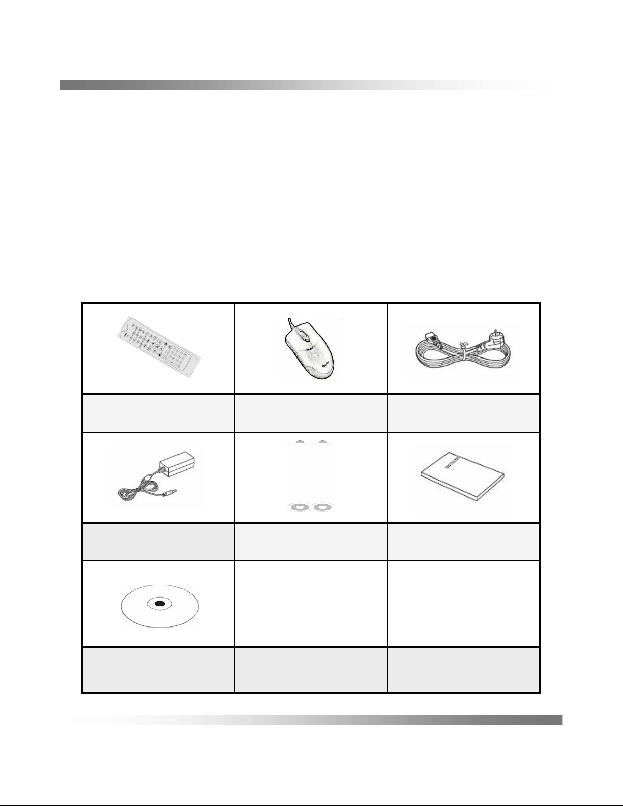
Please unwrap the product, and place the product on a flat place or in the
place to be installed.
Please check the following contents are included in addition to the main unit.
Package Contents
- 9 -
Users ManualBattery AAA x 2DC Power Adapter
Remote Client CD
Power CordMouse (USB)Remote Controller
Page 11

Optional Accessories
- 10 -
Optional Cable Adapter
GC-N50
GC-N40
GC-C40
GC-C30
GC-C20
GC-C10
RJ45(M) to
BNC(F) / RCA(F) / PWR(F)
RJ45(F) to
BNC(M) /RCA(M) /PWR(M)
RJ45(F) to
BNC(M) /RCA(M) /RS485
RJ45(M) to
BNC(F) / PWR(F)
RJ45(M) to
BNC(F) / RCA(F)
RJ45(M) to
BNC(F)
Page 12
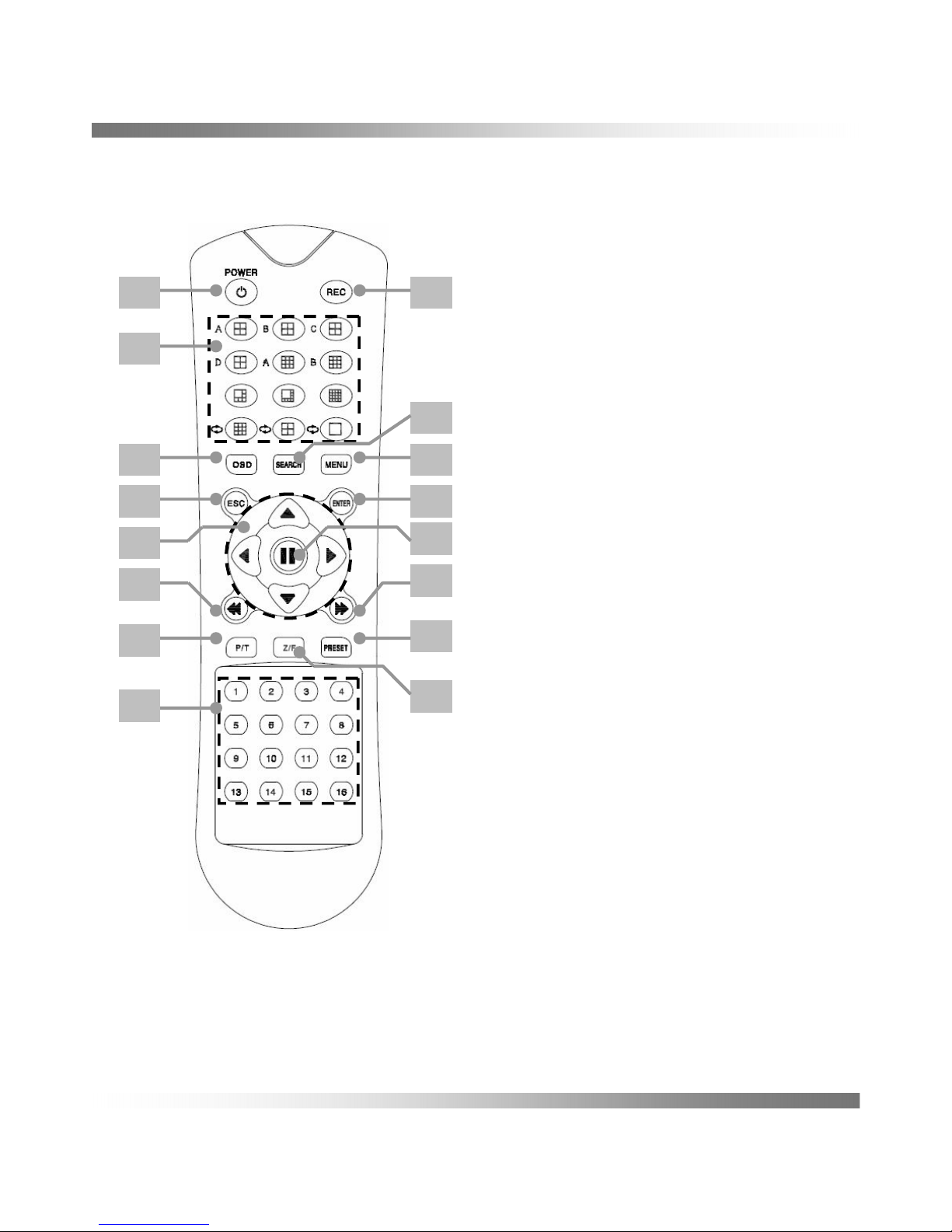
Parts name and Functions
1. POWER : System power On/Off.
2. REC : Start or Stop emergency recording.
3. Split Screen
4. OSD : On or Off OSD of screen
5. SEARCH : Display search menu.
6. MENU : Display main menu.
7. ESC : Cancel Setting or Moving Menu.
8. ENTER : Select to menu.
9. Direction : Moving cursor up/down,
left/right
10. Pause : Used to pause
11. Backward : Backward play
12. Forward : Forward play
13. PAN/TIL T: Sets PTZ Mode ON/OFF.
14. ZOOM/FOCUS : Set zoom and focus of
PTZ camera.
15. PRESET : Displays the Preset Setup
16. Numbers : Used as the numeric input
keys, or displays a single channel
Change ID of Remote control
Select ID numbers and pressing over 3seconds.
The system ID of DVR and ID of the Remote controller should be same to control.
1 2
3
4
5
6
7 8
9
10
11
12
13
15
14
16
Remote Controller
- 11 -
Page 13
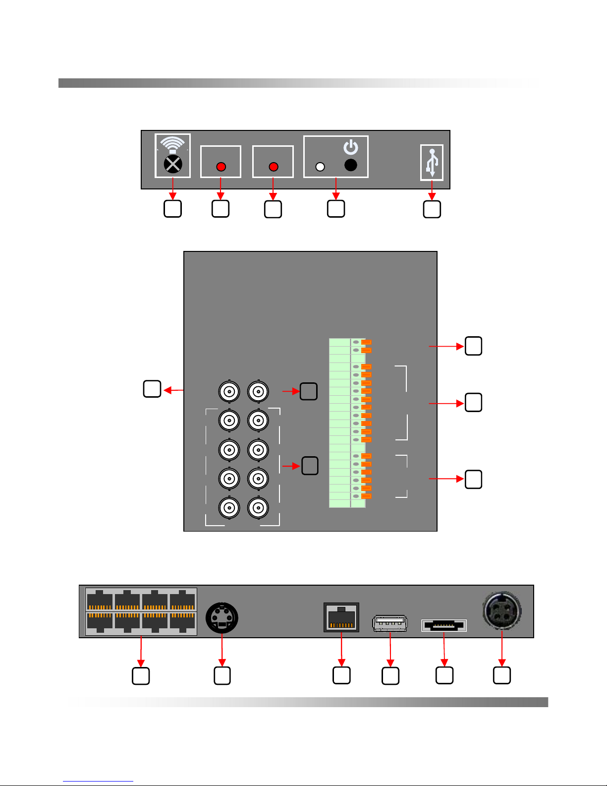
Product exterior
- 12 -
8 Channel – Front, Back and Bottom
Bottom
1
6
52
3
4
RECORD
ALARM
Front
5
1 2
3
4
5
6
4
CVBS
OUT
SPOT
OUT
1 2
3
4
5
6
7
8
CAM
D+
D-
RS-485
1
2
3
4
GND
6
7
8
9
GND
NO
C1
NC
NO
C2
NC
SENSOR
RELAY
OUT
3
1
2
Back
Page 14

- 13 -
Product exterior
4 Channel – Front, Back and Bottom
RECORD
ALARM
Front
5
1 2
3
4
Back
5
6
4
CVBS
OUT
SPOT
OUT
1 2
3
4
CAM
D+
D-
RS-485
1
2
3
4
GND
NO
C1
NC
SENSOR
RELAY
OUT
3
1
2
Bottom
1
52
3
4
Page 15
Exterior Names and Functions
- 14 -
USB port (for data backup and FW update)
USB5
Name
4
3
2
1
NO
Alarm
Power
Red : Power off
Orange: Screen off
Green : Operation
Lighting occurred event.
Lighting during recording
Record
Receive remote control operationReceiver
F
R
O
N
T
Function
POS
6
5
Alarm Output port
Relay out
Composite Video Signal Input Port
(BNC type connector)
Video in
3
Out port composite. (BNC)CVBS out
1
B
A
C
K
4
2
Used for RS-485 communication (D+, D-)
RS-485
Out port Live image. (BNC)Spot out
Alarm Input port
Sensor In
Output Port Separated Video signalS-Video
6
DC12V Power inputPower input
5
Connection terminal for external eSATA HDD or
HDD for backup
eSATA4
Used to Network with other devicesEthernet2
Input Video Signal (RJ45 Type)CAM In
1
B
O
T
T
O
M
USB
USB port (for mouse)
3
Page 16
- 15 -
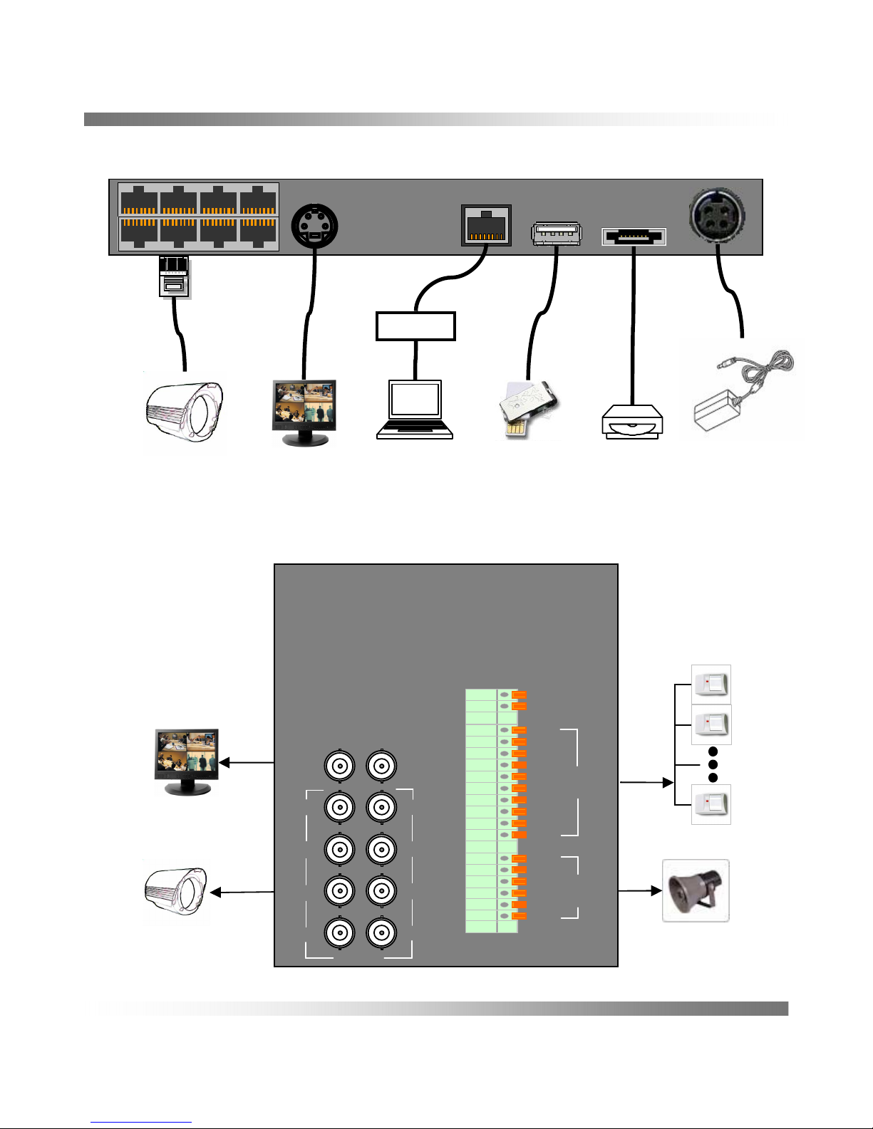
Connecting to other devices
Connecting to the Bottom for 8 channel
eSATA
USB
Devices
RJ-45
Camera In X 8
PC
NETWORK
Monitor
Power Adaptor
DC 12V
Connecting to the Back
CVBS / Spot out
Composite
Alarm Sensor #1-8
CVBS
OUT
SPOT
OUT
1 2
3
4
5
6
7
8
CAM
D+
D-
RS-485
1
2
3
4
GND
6
7
8
9
GND
NO
C1
NC
NO
C2
NC
SENSOR
RELAY
OUT
BNC
Camera Input X 8
Page 17
- 16 -
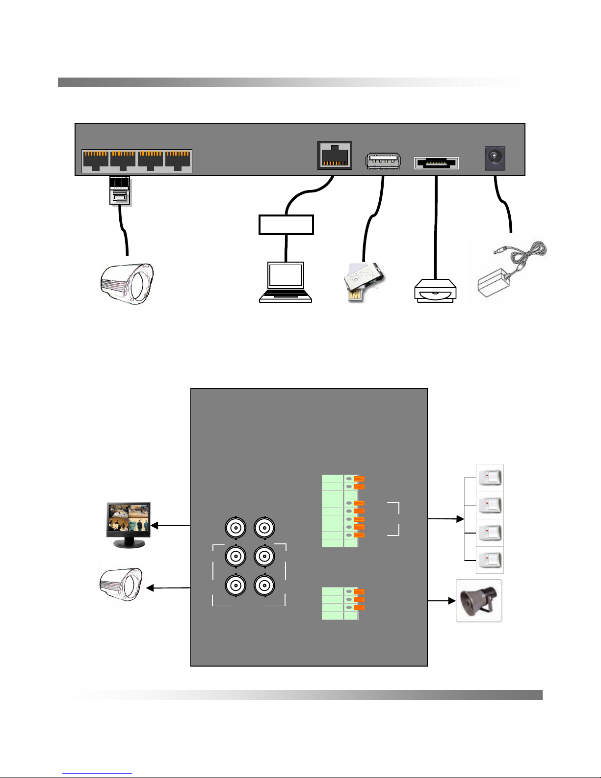
Connecting to other devices
Connecting to the Back
CVBS / Spot out
Composite
BNC
Camera Input X 4
Alarm Sensor #1-4
CVBS
OUT
SPOT
OUT
1 2
3
4
CAM
D+
D-
RS-485
1
2
3
4
GND
NO
C1
NC
SENSOR
RELAY
OUT
eSATA
USB
Devices
RJ-45
Camera In X 4
PC
NETWORK
Power Adaptor
DC 12V
Connecting to the Bottom for 4 channel
Page 18
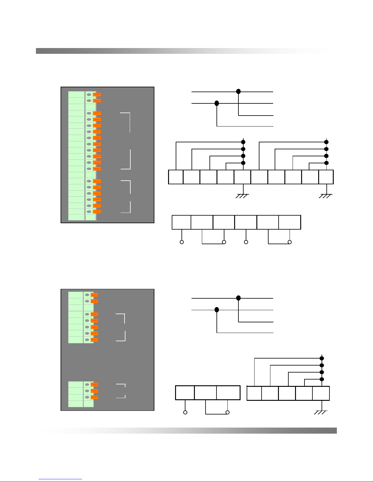
Connecting with the other devices
- 17 -
Connecting the 4Channel Sensor in / Relay out / RS-485
4
G
321
SENSOR IN (ALARM IN)
NCC1NO
ALARM OUT :
0.5A 125VDC / 1.0A 24VDC
D+
D-
RS-485
1
2
3
4
GND
NO
C1
NC
SENSOR IN
RELAY OUT
R+
R-
T+
T-
D+
D-
RS-485
Connecting the 8Channel Sensor in / Relay out / RS-485
NO NCC2NCC1NO
ALARM OUT : 0.5A 125VDC / 1.0A 24VDC
4 G9876G321
SENSOR IN (ALARM IN)
D+
D-
RS-485
1
2
3
4
GND
6
7
8
9
GND
NO
C1
NC
NO
C2
NC
SENSOR IN
RELAY OUT
R+
R-
T+
T-
D+
D-
RS-485
Page 19

RJ-45 Port Layout
- 18 -
Cam Input Pin Assignment
※ Camera Power limit
The power limit is 300mA per camera from the DVR.
If you want to use over 300mA of camera, you must use
separate power sources.
⑧⑦⑥⑤④③②①
⑧⑦⑥⑤④③②①
TALK
VIDEO IN
GND
GND
AUDIO IN
DC 12V
D-
D+
GND
⑤
AUDIO INPUT
④
DC 12V OUTPUT (under 300㎃)
③
RS-485 D-
②
RS-485 D+
①
⑧
⑦
⑥
NAME
TALK OUTPUT
VIDEO INPUT
GND
FUNCTION
CAM IN
(DVR side)
PLUG
(CAM side)
Page 20

Installation the HDD
- 19 -
Managing the HDD
The HDD is very sensitive device, please ensure that the HDD free from shock.
We are not liable for any damage to the HDD incurred by the user’s carelessness
and miss use.
The HDD may be damaged if the DVR is moved or impacted during the HDD operation.
Please backup data as often as possible to minimize the risk of data loss from a
damaged HDD.
The HDD also may be damaged if the DVR is stopped by a power off during the HDD
Operation.
Installation the HDD
There are many factor that cause an electric shock and a fault inside the DVR.
You can contact the retailer to get information including the compatibility list before
installation the HDD.
You must check the brand and Model name that is in the compatibility list before
Installation.
Please check the number of screws and connection wire after Installation the HDD.
If there are wrong connection or feeling the wire, it causes a fault of the DVR .
Page 21

Getting Started
- 20 -
Starting the System
1.Connet the power cable of the DVR
to the wall inlet.
2. Press the Power button on the front panel
or remote control.
3. You will see the initialization screen.
The initialization process will last about 3 minutes.
4. The live screen appears with a beep.
Power off the System
1. You can shut down the system only if you have
logged in to the DVR.
You should have the POWER OFF permission
to shut down the system if you are not an admin.
2. Press the <POWER> button on the remote control
or the Power button of the front panel more than
2 seconds.
3. The “POWER OFF” confirmation window appears.
4. Use Mouse or remote control or the front panel
to move to press and or click <YES>.
The system will be Power off.
Screen ON/OFF
Press the Power button of the remote control or the front panel of DVR shortly.
The DVR works normally during screen off.
<Initial display screen>
<Confirmation window>
Page 22

Getting Started
- 21 -
Started Login
To access a DVR or restricted menu, you should have logged in to the DVR.
1. In live mode, right-click of mouse.
You will see the context sensitive menu as
in the right figure.
2. The login dialog will also appear if you press
a menu button on the remote control or mouse
when the corresponding menu requires logging in.
3. Select user, input password and press <OK>.
• ADMIN : Permitted all DVR function.
The default password of “ADMIN” is “1234”.
• USER1 ~ USER8 : Limited permission by preset
of ADMIN.
<Login Window>
Page 23

- 22 -
Icons on the Live Screen
You can check the status or operation of the DVR with the icons on the live screen.
Press <CH1> and <CH1>, drag and drop <CH1> to <CH4> and right click of the mouse.
You can learn the operation of the live screen after pressing the bar of the bottom.
Live Mode
Stop to alarm if activatedAlarm
Go to main menuMain menu
Indicates Camera numberCamera number
Show live menu barShow Launcher
Rotate split screen 4, 8 split / or sequence dwell
Hide live menu barHide Launcher
Display AUDIO ON / MUTESound (Option)
Transferred Sound by MICTalk
Indicates current used capacity HDDHDD
On or off camera number on the live status
Recording process and canceled
Screen Mode
Indicates current date and timeDate and time
DescriptionName
1
2
3
4
CAM 03
CAM 01
1
2
43
CAM 04
CAM 02
Page 24

- 23 -
Main Menu icons
You can access a desired menu by right clicking or <MENU> of the remote control in live
screen.
Some menus are protected depending on the user right that assigned by “ADMIN”.
You can return to the live screen by the right clicking quickly.
※ Designated numbers ( ~ ) mean sequence of operation manual.
Setting the Menu
1 12
1
2
3
4
5 6 7 8
9 10 11 12
Page 25

- 24 -
Menu Explanation
Back Power Off
MAIN MENU
See Help mode <49 page>
See PTZ Control setting mode <48 page>
See HDD setting mode <47 page>
See Network setting mode <44~46 page>
See Backup setting mode <43 page>
See Sound setting mode <42 page>
See Display setting mode <41 page>
See Record setting mode <30~35 page>
See Replay setting mode <38~39 page>
See Camera setting mode <36~37 page>
See Event setting mode <40 page>
See System setting mode <25~29 page>
1
2
3
4
5
6
7
8
9
10
11
12
Page 26

- 25 -
You can setup the system properties, devices, and options for recording, event, backup
and network.
1.1 Setting the System Name
You can set and change DVR name
and this name is important to access
MAC NAME SERVER without entering
IP address.
• Click <SYSTEM NAME>
Then appears virtual keyboard.
• You can set and change DVR name.
• You can finish virtual keyboard by clicking
the right mouse button or enter key.
Operation Sequence
MENU è SYSTEM è SYSTEM NAME
1. SYSTEM
※ Using Virtual Keyboard
① For alphanumeric inputs, the virtual
keyboard window appears.
② Click the mouse a desired character.
③ You can easily input a small letter,
a capital and special characters.
: close the keyboard
: delete a previous character.
: change character set.
<“SYSTEM” menu>
Page 27

- 26 -
1.2 Password
ADMIN can set permissions of each user over the DVR's specific function and settings.
Setting Permission
Manager can set restricted access for all general users.
• Checked ( ) : Accessible
• Not checked : Restricted
Setting the user’s Name and Password
Manager can set or change manager’s and user’s password including name.
※ By default, the password of “ADMIN” is “1234”.
Operation sequence
MENU è SYSTEM è PASSWORD
1. SYSTEM
<“PASSWORD” menu> <“NEW PASSWORD” menu>
Page 28

- 27 -
1.3 Setting System ID
If there are many DVRs at near place, they
are able to operate simultaneously when
press remote controller. But One DVR
make controllable by designated ID Number
Of System ID number.
Select ID numbers and Pressing over 3 Sec.
The system ID of DVR and ID of the Remote
Controller should be same to control.
Operation Sequence
MENU è SYSTEM è SYSTEM ID (1~16)
1.4 System Configuration
You can Load, Save, Delete the DVR settings
by using a storage media [SYSTEM], [USB].
[SYSTEM CONFIG]
Load or Save settings data to a storage
device.
• Storage : Display Storage media there are
USB and SYSTEM.
• Save : Save configuration to storage media.
• Load : Fetch configuration from storage
media.
• Delete : Delete the configuration.
[FACTORY DEFAULT]
If Factory Default is pressed, a confirmation
dialog for “System will be restarted” window.
Click <YES> to initialize the system to the
factory default and system rebooting.
Operation Sequence
MENU è SYSTEM è SYSTEM CONFIG
è LOAD / SAVE or FACTORY DEFAULT
1. SYSTEM
<“SYSTEM” menu>
<“SYSTEM CONFIG” menu>
<“FACTORY DEFAULT” menu>
Page 29

- 28 -
1.5 Time / Date Change
You can setup the current Date / Time.
• DATE/TIME : Sets the date and the time
• DATE FORMAT : Select the date format
• TIME FORMAT : Select the time format
• NETWORK TIME SERVER : Enter an IP
or URL address of the time server.
• [SYNC.] : You can set the DVR’s current
time from selected Time Server.
• TIME ZONE : Sets the time zone of your
area based on the Greenwich Mean Time (GMT).
• SUMMER TIME : Set up Daylight Saving Time.
Operation Sequence
MENU è SYSTEM è TIME/DATE è CHANGE
1. SYSTEM
<“TIME/DATE” menu>
Page 30

- 29 -
1.6 Firmware Update
• Connect a device storing the software
to be updated. Upgradeable device is
USB memory. (It may take several seconds
to recognize the device.)
• Select <UPDATE> from [SYSTEM] menu.
• Choice F/W version and click <UPDATE>.
While updating, it shows the progress bar.
• Click <SEARCH>, if the firmware does not
recognize.
• When the updating is done, it automatically
restarts.
Do not turn the power off until it finishes restarting.
If “UPDATE FAIL” appears, retry but continued failure, consult the service center for
assistance.
Operation Sequence
MENU è SYSTEM è F/W UPDATE è SEARCH è UPDATE
1.7 Hardware / IP / MAC Address etc
• You can check some information
about Firmware, Hardware version,
IP Address and MAC address.
1. SYSTEM
<“F/W UPDATE” menu>
Page 31

- 30 -
2.1 Setting the Record
You can setup scheduled recording, event recording and other recording related settings.
You can set each channel’s resolution, quality and frame for event recordings.
Using the mouse in [RECORD] window to move to [SIZE], [F/S], [QUALITY] and Choice
conditions you want size, F/S and quality.
• SIZE : Sets the resolution of the recorded screen.
• F/S : It means the frames recorded per a second that is record rate
• QUALITY : Sets the recording quality.
• AUDIO : Sets the sound recording.
2. RECORD
Samples each half of horizontal and vertical screen.
352 X 240 (NTSC)
352 X 288 (PAL)
CIF(S)
Samples original screen size.
704 X 480 (NTSC)
704 X 576 (PAL)
Full D1(L)
Samples half of the horizontal screen.
704 X 240 (NTSC)
704 X 288 (PAL)
Half D1(M)
DescriptionSizeName
Page 32

- 31 -
2.2 Setting the event
You can set recording options for sensor, Relay and Motion.
Sensor Detection
You can set the sensor’s operating condition.
Using the mouse may help easy setup.
• SENSOR : Sets the operation mode of
sensors. There are modes [NO], [NC], [X]
- N.O (Normal Open) : Sensor is opened.
If the sensor is closed, it generates alarm.
- N.C (Normal Close) : Sensor is closed.
If the sensor is open by interruption,
it generates alarm.
- X : Sensor does not operate.
Operation Sequence
MENU è RECORD è SENSOR
Relay Detection
You can set the relay operating condition.
Operation Sequence
MENU è RECORD è RELAY
• The settings of all channels are changed when pressing the bars for <AUDIO>,
<SENSOR> and <RELAY>.
2. RECORD
<“RECORD” menu>
<8CH > <4CH>
Page 33

- 32 -
2.3 Motion Detection
You can set detection region and motion sensitivity as well as the alarm signal output.
When the motion detection region is set, it detects motion within the area.
• Sensitivity
setting the sensitivity and high is
more sensitive.
Setting the Motion Area
① Select <MOTION>.
At first sets the sensitivity level.
② Select <AREA>.
③ When “AREA” window appears,
select the area of motion detection.
• ALL SET : All cells are set to be motion
detection area.
• ALL CLEAR : All cells are removed from
the motion detection area.
• WINDOW SET : Using the mouse drag
selected cells are set to be the motion
detection area.
• WINDOW CLEAR : Using the mouse drag
selected cells are removed from
the motion detection area.
• EACH CELL : You can set or clear the cell
for each cell.
• EXIT : save the setting and move to the
record menu.
Operation Sequence
MENU è RECORD è MOTION AREA
2. RECORD
<“RECORD” menu>
Page 34

- 33 -
Setting display of the Motion Area
2. RECORD
Page 35

- 34 -
2.4 Recording Schedule
You can setup scheduled recording, event recording and other recording related settings.
RECORDING SCHEDULE
Make your reservation on a date and time to schedule the recording on specified time and
channel.
If selected <ALL>, “All Channels and time” are selected.
Event Recording
You can set the beginning and ending point of a recording on an event.
Event recording can be program based on event, time and channel.
• PRE EVENT : The recording will be kept from the point of set pre-event time earlier
than the actual occurrence of an event.
If it is set to 5 seconds, the recording begins from 5seconds before the event.
• POST EVENT : The recording will be kept to the point of set post-event time after
than the actual end of an event.
If it is set to 5 seconds, the recording ends in 5seconds after an event.
• HOLIDAY :You can set specific dates to Holidays according to your preferences.
Use to mouse <SETUP> move to virtual calendar and click any day.
• ALL : If <ALL> are selected, you can program the schedule at same time.
• Event : Select <TIMER>, <MOTION>, <SENSOR>, <MOTION + SENSOR>, <NONE>
and then select channels and time using the mouse or remote controller.
Drag function also accept including click action in case of mouse.
• SAVE : The settings are saved to memory after pressing the <SAVE>.
Operation Sequence
MENU è RECORD è RECORDING SCHEDULE
2. RECORD
Page 36

Setting the recording
2. RECORD
- 35 -
Page 37

- 36 -
3.1 Camera Setting
You can set CHANNEL NAME, COLOR, COVERT, RELAY and PTZ of a camera.
• CHANNEL NAME : Using Virtual Keyboard
you can input channel name.
• COLOR : The video appeared on the
screen may vary depending on the
channel’s camera, configure the DVR
display to your preferences.
- Select a channel and press <SET>.
You can adjust the [Brightness],
[Contrast], and [Color] of the selected
channel, and <EXIT> to return the camera
menu.
In case of the remote controller
[Brightness] : ,
[Contrast] : ,
[Color] : ,
• COVERT : Shows nothing but an empty
screen while the recording continues
for privacy protection, it does not display
the video while the recording continues.
• RELAY : You can set relay operation.
Operation Sequence
MENU è CAMERA
3. CAMERA
<“CAMERA” menu>
Page 38

- 37 -
3.2 PTZ Camera Setting
You can set CHANNEL NAME, COLOR, COVERT, RELAY and PTZ of a camera.
Set the values of each communication setup
of the remote device.
To use Camera’s PTZ functions, ID and
protocols of each camera and DVR should
be matched.
• CAMERA CH : Channel number.
• CAMERA NAME : Channel name.
• PTZ : PTZ settings ON, OFF.
• ID : Set a same ID of the connected
camera of each channel.
• VENDOR : Select the name of the camera
manufacturers.
• MODEL : Select the camera model.
• BAUDRATE : Baudrate settings of the DVR,
PTZ camera and system keyboard should
be matched for proper operations.
You can check the camera’s ID and protocol
if you turn the camera off and on after
connecting it to the DVR.
Please check detail information with user
manual about PTZ camera.
Operation Sequence
MENU è CAMERA è PTZ
3. CAMERA
<“CAMERA” menu>
<“PTZ CAMERA” menu>
Page 39

- 38 -
4.1 Search
You can perform the search for recorded data by the time or by the search criteria
such as an event.
You can choice one of the storage media
HDD, USB and eSATA.
You can search for recorded data of
a desired time.
The record data on the specific date will
be listed.
The display bar is different color according to
the data type.
• RECORD START : Start time of the
recording.
• RECORD END : End time of the recording.
• REPLAY START : Enter a time to perform
the search or use mouse click.
Choose a date using the calendar to
search, you will see that the date of the
recording data
• START : Replay will be start from selected
time.
You can search the video data more easily
with the calendar.
Operation Sequence
MENU è REPLAY è Select time è START
4. REPLAY
<“REPLAY” screen>
<“REPLAY” menu>
Page 40

- 39 -
4.2 Event Search
You can specify a time period and search all channels, some channels, all events,
motion detection or sensors. There are Timer, Motion, Sensor Event Search.
- Time Search : Enter a desired date and time and select search to go to the
video at the specified date and time.
- Motion Search : If a motion is detected in each channel, you can set a desired
area to perform the search. Searches for the motion area for each channel specified
in motion area
- Sensor Search : You can search for data in the sensor device that is connected
to the DVR
Operation Sequence
MENU è REPLAY è Timer or Motion or Sensor è START
4.4 Replay
You can replay the data stored in the HDD, USB and eSATA.
All channel will be displayed at same time.
• Day / Time : Displays the time and date of the current video.
• Speed : Supports various speed options of x1(-1), x2(-2), x4(-4), x8(-8), x16(-16),
x32(-32) and x64(-64), x128(-128), x256(-256), x512(-512)
• Slow : Support x1(-1), x1/2(-1/2)
If you press this key during pause, you can see frame by frame.
• Sound : You can control speaker volume.
If you want to return to the Live screen in Play mode, click <X : Exit> in the menu.
Operation Sequence
MENU è REPLAY è START è Replay controller
4. REPLAY
Exit
Slow
Play
Slow
Rewind
Fast
Play
Play /
Pause
Fast
Rewind
Replay
Speed
Date and Time Sound
Page 41

- 40 -
Event Log
You can browse logs on the system and events.
Event log shows recorded events on system
which system log shows log and timestamp
on every system startup, system shutdown,
and changes on system record, camera,
motion, sensor and remote detections.
It also shows the log and its timestamp.
• START : Starting search day.
• END : Ending search day.
• SEARCH : Start search.
• BACKUP : Backup to USB the logs.
The file format of the backup data is “txt”
Operation Sequence
MENU è EVENT LOG
5. EVENT LOG
<“EVENT LOG” menu>
Page 42

- 41 -
Display
You can configure information to be displayed and its format for spot out monitor.
• CAMERA NAME : Display camera name
in live screen.
• EVENT ICON : Display event icon
in live screen.
• ALARM POP UP : Pop up display time of
the CH after event occurs.
• MOTION POP UP : Pop up display time of
the CH after a motion event.
• SPOT OUT : You can select the channel
for the spot monitor.
• SEQUENCE : Select channels that will be
displayed sequentially.
• SEQUENCE DWELL : Sets the dwell time
Operation Sequence
MENU è DISPLAY
6. DISPLAY
<8CH>
<4CH>
<“DISPLAY” menu>
Page 43

- 42 -
Sound
Each channel can be set to sound and buzzer can be set related items.
• AUDIO IN : You can control the sound
corresponding to the channel in Live mode.
(Option)
• BUZZER : Buzzer can be set followings.
- REMOTE CONTROL : Buzzer will beep
when pressing Remote control.
- SENSOR, MOTION, VIDEO LOSS :
Sensor, Motion, Video loss can beep
the buzzer.
- DURATION : it means beeping time
- MODE : beeping mode.
※ Latched : beeping is activated based on setup duration.
※ Transparent : beeping is activated during event period.
Operation Sequence
MENU è SOUND
7 SOUND
<“SOUND” menu>
Page 44

8. BACKUP
- 43 -
You can check the backup device and set the backup schedule by channel and by time.
1. Backup
• RECORD START : the start time of the Record.
• RECORD END : the end time of the Record
• BACKUP START : the start time for the backup
• BACKUP END : the end time for the backup
• CHANNEL : the channels to be backup. You can select multiple channels.
• VIDEO : Video backup
• AUDIO : Audio backup
• AVI / DVR : Select the backup data format.
- AVI : file format that can be played back by using external viewers such as Windows
Media Player on a PC
- DVR : file format that can be played back by the DVR or the DVR viewer.
• USB / eSATA : Select the backup device
• START : Backup start.
Operation Sequence
MENU è BACKUP
<“BACKUP” menu>
Page 45

9. NETWORK
- 44 -
9.1 Network Configuration
It provides networked monitoring of Live screen from a remote place, and supports mail
forwarding function with events.
You can configure the network environment
and method.
• IP MODE : You can select Static IP or
Dynamic IP
- STATIC IP : You can directly input IP
address, Gateway, Subnet Mask.
- DYNAMIC IP : IP address, Gateway,
and Subnet Mask are set automatically.
• IP ADDRESS, GATEWAY, SUBNET MASK
When you use the remote controller,
use CH11~CH16 keys in order to input “.”.
• PORT : Set the communication port.
• WEBPORT : Set the web server port.
• MAC ADDRESS : Physical address of the DVR
• DDNS : On or Off DDNS
• E-MAIL NOTIFICATION : the function that send information to assigned E-mail
based on system event.
Operation Sequence
MENU è NETWORK
<“NETWORK” menu>
Page 46

- 45 -
9.2 DDNS (Dynamic Domain Name System)
You can set the DDNS site for a remote user’s network connection
DDNS is a short form of Dynamic Domain Naming System.
DNS (Domain Name System) is a
service that routes a domain name
consisting of user friendly characters
(ex: www.google.com) to an IP address
consisting of numbers (64.233.189.104).
DDNS (Dynamic DNS) is a service that
registers a domain name and the floating
IP address with the DDNS server so that
the domain name can be routed to the IP
address even if the IP is changed in a
dynamic IP system.
• DDNS : Select ON or OFF
• SERVER : The server name that support DDNS service provider.
( http://www.no-ip.com
)
You must register the “USER ID” and the “PASSWORD” before using the DDNS function.
• HOST NAME : Enter the HOST NAME that is registered to the DDNS service provider.
(ex. dvr.no-ip.org)
• USER ID : Enter the USER ID that is registered to the DDNS service provider.
• PASSWORD : Enter the PASSWORD that is registered to the DDNS service provider.
Operation Sequence
MENU è NETWORK è DDNS
9. NETWORK
<“DDNS” menu>
Page 47

9.NETWORK
- 46 -
9.3 E-Mail Notification
You can send an e-mail to a DVR-registered user at a specific time interval or
if an event occurs.
• EVENT
You can set the type of the event
that will be sent to the user.
Using the mouse may help easy setup.
- SYSTEM
- RECORD
- CAMERA
- MOTION
- SENSOR
- REMOTE
• E-MAIL ADDRESS :
You can set E-mail address
• INTERVAL TIME : Set the event interval.
If a series of events occurs, the e-mail will be sent at the specified interval,
not on each event.
• SMTP SERVER : Enter a server to connect to.
• PORT : Sets the communication port/
• AUTHENTICATION : Setup authentication on/off.
If the Mail server users user authentication, setup authentication on.
• USER ID : Enter a user to use authentication when connecting to the mail server.
• PASSWORD : Enter the password of the mail server.
Operation Sequence
MENU è NETWORK è E-MAIL NOTIFICATON
<E-MAIL NOTIFICATION>
Page 48

10. HDD
- 47 -
Setting HDD
You can check information for the HDD.
• OVERWRITE
- YES : Overwriting new recoding data
from the first area of the HDD after
the hard disk was full.
- NO : New recoding will be stop
after the hard disk is full.
.
• HDD FULL ALERT : “HDD FULL” event
is activated when the used capacity of
the HDD is reached setting value.
• HDD FAIL / FULL
- RELAY OUT : Relay out when HDD event occurred.
- BUZZER ON / OFF: Buzzer ON when HDD event occurred.
- DISPLAY ON / OFF: Alert display ON when HDD event occurred.
• FORMAT : If press <YES> after conformation window, formatting will be start.
“All data will be cleared after formatting”, so you must backup the data before format.
• CAPACITY / USED : Shows the capacity of the HDD and used status.
Operation Sequence
MENU è HDD
<“HDD” menu>
Page 49

11. PTZ CONTROL
- 48 -
Controlling a PTZ device
The PTZ is activated after setting the camera as PTZ at “CAMERA” setting menu.
You can use one camera to perform all functions of PAN, TILT and ZOOM for monitoring
multiple places and set the preset to your preference in a desired mode.
• PAN / TILT : Control the PAN and TILT of PTZ camera.
Click the PAN/TILT button on the control panel or press the Direction button (U/D/L/R)
after pressing P/T( ) button on the Remote control.
- PAN : è - TILT : è
• ZOOM/FOCUS/IRIS : Control the ZOOM/FOCUS and IRIS of PTZ camera.
Click the ZOOM/FOCUS/IRIS button on the control panel or press the Direction button
(U/D/L/R/FF/REW) after pressing Z/F( ) button on the Remote control.
- ZOOM : è - FOCUS : è - IRIS : è
• PRESET : A preset is a set of specific target points of a PTZ camera.
The number of preset is depended on maker and model.
- SET : You can save the preset number.
- GO : You can run a number of preset settings .
- PRESET setup : è 1~0(10) è SET ( )
- PRESET run : è 1~0(10) è GO ( or )
* Please refer to the user manual of PTZ camera about function and setting.
* You must connect separated DC adaptor because PTZ camera consume a large
current. If you connect PTZ camera to DVR directly, it cause out of order
Operation Sequence
MENU è PTZ CONTROL
PAN/TILT ZOOM/FOCUS/IRIS
CHANNEL PRESET
EXIT
Page 50

12. HELP
- 49 -
Page 51

- 50 -
Installing the SMART VIEWER
Execute “SmartViewer.exe” of the CD that packed with DVR set, then below screen will
be displayed on your monitor of the PC.
Controls full screen, small screen and Exit
Changes full screen or spilt screen
Controls audio output and microphone input level
Connection Information (System name, IP Address)
Displays current time and date
The screen of connected DVR.
Controls PTZ camera
Connect/Disconnect, DVR List
Terminal mode, Live mode, Backup, Replay, Event Log, DVR Setup (Menu)
ExplanationNO
1
2
3
4
5
6
7
8
9
13. REMOTE CONTROL
2
3
4
1
5
9
6
8
7
Page 52

13. REMOTE CONTROL
- 51 -
DVR LIST SETUP
1. Open your DVR SETUP menu ( ) and input the IP/URL, name of DVR .
2. Set the ADMIN ID and password same to those of the DVR ADMIN.
For users, enter the DVR user ID and password.
Cancel
OK
Delete
Modify
ADD
Password
ID
Port
URL/IP
Name
DVR List
Name
Saved current setting and exit the setup window
Cancel all changed data and exit
Delete DVR List
Input ID of connecting DVR (ADMIN or User)
Save modified data of the DVR List
Add new DVR List after input new DVR information
Input DVR name
Listed Registered URL/IP
Input user’s password of DVR
Input Port number of DVR
Input DVR IP / URL Address
ExplanationNO
1
2
3
4
5
6
7
8
9
10
11
1
2
3
4
5
6
7
9
8
10 11
Page 53

- 52 -
• Live Screen
This is a live screen that connected a DVR.
If you select one channel, the channel
will be pop up as full screen.
• Connecting the Smart Viewer
1. Click <DVR Setup> and make DVR list
after input DVR information.
2. Find and click the <DVR List> after pressing
the DVR list icon.
3. Click <Connect/Disconnect> icon to connect.
4. Live screen of the DVR will be display on monitor.
5. You can control the DVR with several function.
6. Click <Connect/Disconnect> icon to disconnect
• Changing the live screen
You can select several split mode,
sequence mode and full screen.
Click mouse on the tool bar.
• Audio output and MIC input
Audio output and MIC input are controlled by “-” and ““+”.
Click the number “ ” that means channel,
the channel number will be increased.
13. REMOTE CONTROL
Connect /
Disconnect
DVR List
Page 54

- 53 -
• Controlling PTZ camera
You can control the PTZ camera with the same method as DVR.
- You can zoom in or out the image by using “-” and “+”.
- You can adjust the focus by using “-” and “+”.
- You can adjust the entering light amount by using “-” and “+”.
• Connection Information
When connect DVR,
connection information of DVR appears.
13. REMOTE CONTROL
Page 55

- 54 -
• Function
① Terminal mode ② Live mode
③ Backup ④ Replay
⑤ Event Log ⑥ Menu
① Terminal mode
You can control all function of the DVR in this mode (Terminal mode) via SmartViewer.
② Live mode
This mode (Live mode) is displayed inputted video only.
③ Backup
1. Click ‘BAKCUP’( ) button, ‘BAKCUP’ window appears.
2. Select the channel to be backup. You can select multiple channels.
3. Set ‘Start time’ and ‘End time’ for backup.
4. Click ‘Backup Start’ button, to start backup.
While saving the data, it shows the progress bar.
※ The AVI files will save the AVI files folder.
( .\SmartViewer\bakcup\avi\ )
13. REMOTE CONTROL
①
②
③
④
⑤
⑥
Page 56

- 55 -
• Function
④ Replay
1. Click ‘REPLAY’( ) button, SmartViewer changes to ‘REPLAY’ mode.
2. Select the date in calendar and time in search bar that you want to playback.
3. You can control replay via replay controller.
13. REMOTE CONTROL
2
3
4
1
5
6
7
Calendar :
Controls screen mode
Search bar : Search & indicate camera recording situation by time bar
The screen of replay
Controls volume
Replay controller
Replay time & date
ExplanationNO
1
2
3
4
5
6
7
Page 57

- 56 -
• Function
⑤ Event Log
1. Click ‘EVENT LOG’( ) button, ‘Event Log Search’ window appears.
2. Set Start and End time for search.
3. Select event for search.
4. Click ‘Search’ button, event log is displayed.
5. If you want to save the event log, click ‘Backup’ button.
※ The Event log files will save in the elog files folder.
( .\SmartViewer\bakcup\elog\ )
The file format of the backup data is “txt”.
13. REMOTE CONTROL
Page 58

- 57 -
What is Web Viewer?
Web Viewer allows remote access to your DVR.
You can access to live video, archived video, PTZ control etc.
DVR FEATURES
• Remote access from a standard browser
Example: Explorer, Opera, Chrome, Firefox, Safari, etc
• Supports 1, 4, 8 camera viewing formats.
• Control function for refresh time.
Connecting method
1. Open the web browser and input DVR IP to address window, then Enter.
The login screen displays on the web browser.
2. Input DVR’s ID and Password, then click <LOGIN> button.
The DVR screen will be displayed on the web browser.
3. If you click one channel, the channel will be displayed as full screen.
The split screen will be displayed after one more click.
4. You can control the refresh time by using the F/S control.
If communication speed is slow, reduce the F/S in order to get images steadily.
If communication speed is good, increase the F/S for smooth images.
13. REMOTE CONTROL
Page 59

Connecting the Smartphone
• The connection method is same as web browser.
1. Open the web browser and input DVR IP to address window, then Enter.
The login screen displays on the web browser.
2. Input DVR’s ID and Password, then click <LOGIN> button.
The DVR screen will be displayed on the web browser.
2. If you click one channel, the channel will be displayed as full screen.
The split screen will be displayed after one more click.
3. You can control the refresh time by using the F/S control.
If communication speed is slow, reduce the F/S in order to get images steadily.
If communication speed is good, increase the F/S for smooth images.
- 58 -
13. REMOTE CONTROL
 Loading...