

Page 1
www.fsm.ag
Telefon +49 7661 9855 0
vertrieb@fsm.ag
FSM AG
Erich-Rieder-Straße 2
D-79199 Kirchzarten
1
Operating instructions
Pressure sensor | Type DPS/ APS
1612_02
Page 2
www.fsm.ag
Telefon +49 7661 9855 0
vertrieb@fsm.ag
FSM AG
Erich-Rieder-Straße 2
D-79199 Kirchzarten
2
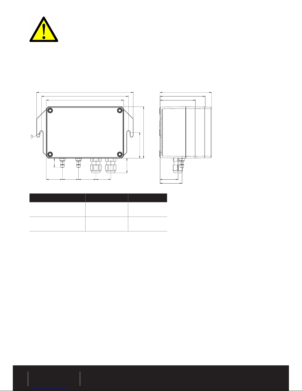
Drawing
Version Supply Output
Four-wire
1 = N
2 = L1
3 = 0
4 = output
Three-wire
1 = 0
2 = VDC
3 = 0
4 = output
Calibration
The pressure sensors are calibrated in the factory. If necessary recalibrate according to the calibration instructions.
Safety precautions and personnel protection
For the correct and safe use of this instrument it is important that the VDE (or similar association) safety precautions as
well as the safety precautions of the professional/trade association having liability for industrial safety regarding the operation
of electrical instruments and equipment be observed.
Installation
Using both straps the pressure sensors are connected to the mounting ttings. Avoid having interference sources (transformers,
transmitters, motors etc.) or heat sources in the neighbourhood. Shocks or vibrations at the mounting connection
can cause distortions to the output signals. Connections should be vertical, i.e. the pressure connections should point
downwards. The sensors are calibrated in the factory for such mounting conditions. In addition the formation of condensation
in the pressure tubing of the sensor is also reduced.
Preparations befor operation
Prior to operation remove the housing cover. Electrical connections are made using terminal connections. Take care when
connecting the power supply. Do not connect the power supply to the output connectors. Instruments with a DC power
supply are reverse-connect protected. The output signal of the sensors is short-circuit protected.
The pressure transducers of the DPS type series are suitable for detection of excess pressure, low pressure or differential pressure of non-aggressive gasses. Pressure measurement is carried out using CuBe membranes sensitive to the respective pressure
range. Using an inductive system the membrane systems are ‘force-free’ scanned.
Note: Commissioning may only be reliable, trained or assigned personnel.
25 25 27 23
23
14,50
150
135
120
40
80
5
80
55
70
28
34
Page 3

www.fsm.ag
Telefon +49 7661 9855 0
vertrieb@fsm.ag
FSM AG
Erich-Rieder-Straße 2
D-79199 Kirchzarten
3
After switching on the power supply the output signal can be measured. Variations in the output signals may be due to two
possible causes:
1) The warm-up time of the sensor is about one hour. After this period the sensor signal should be stable for zero
differential pressure and constant ambient temperature.
2) For small pressure ranges a measurable zero-point shift due to ambient conditions can occur. This error can be
corrected for by adjusting the zero-point potentiometer of the sensor after the warm-up time is completed. (Set the output
signal of the sensor with both pressure inputs open to the nominal value).
Connection the pressure to be measured
The pressure to be measured should be connected to the „+“ input. APS sensors (absolute pressure) have only one pressure
connection. Do not blow into this pressure connection. This can damage or destroy measuring cells for pressures up to
100 hPa.
Transport and storage
Ambient storage temp. range: -10 °C to + 70 °C For transport make sure that both pressure inputs of differential pressure
sensors are open. Air transport of absolute pressure sensors should only be done in pressure compensated cabin.
Calibration instructions
Use the following tools for calibration of the pressure sensor:
Reference pressure
Precision manometer, digital manometer, DPC-pressure calibtraor; for APS use absolute pressure
reference
Pressure source Pumps, bellows or DCP-pressure calibrator
Supply Depending on the pressure measuring transducers
Measuring instruments Multimeter to measure the output current or voltage signals
Calibration of type DPS
1. Connect the correct power supply between terminals 1 and 2.
2. Connect the multimeter to measure the output signals (current or voltage) between terminals 3 and 4.
3. Wait for the sensor to warm-up (ca. 1 hour).
4. To adjust the zero-point both pressure inputs must be open. Using the trimmer TP1 set the display of the multimeter to 0 Volt
(for current output 0 (4) mA).
5. To adjust the full-scale deection using a T-connector apply the rated pressure to the pressure connection of the sensor, the
pressure source and the pressure reference. Using the trimmer TP2 set the display of the multimeter to 10 Volt (for current
output 20 mA).
Page 4

www.fsm.ag
Telefon +49 7661 9855 0
vertrieb@fsm.ag
FSM AG
Erich-Rieder-Straße 2
D-79199 Kirchzarten
4
www.fsm.ag
Calibration of type APS
1. Connect the correct power supply between terminals 1 and 2.
2. Connect the multimeter to measure the output signals (current or voltage) between terminals 3 and 4.
3. Wait for the sensor to warm-up (ca. 1 hour).
4. Using a T-connector connect the pressure input of the sensor with the pressure source and the absolute pressure reference.
Adjust the absolute pressure so that the output signal of the sensor is 0 Volt (for current output 0(4) mA). Using the trimmer
TP1 set the multimeter display to the corresponding value.
5. Apply an absolute pressure to the pressure input to the sensor so that the output signal is 10 Volt (for current output20 mA).
Using the trimmer TP2 set the multimeter display to the corresponding value.
Response times
C14: Capacitor for electronic attenuation
Response times (t):
> t ≈ R x C
> C ≈ t / 50 kOhm
> R = 50 k
Notes
Additional trimmers (TP3 to TP7) are installed in some options:
> TP3: Matching trimmer for sensors with „+/-„ measurement ranges.
> TP4: Adjustment of the internal resistance for current output.
> TP5/TP6: Adjustment trimmer for special pressure ranges and special output signals.
> TP7: Scaling and matching of analog and digital displays.
These trimmers are initially set in the factory. Adjusting these trimmers should only be done after consultation with the
supplier. Readjustment of the sensor does not require readjustment of the trimmers TP3 to TP7. Only the trimmers TP1
and TP2 must be readjusted if necessary according to the calibration instructions.
 Loading...