


MULTI-ROUTER
TCP 0211
INSTALLATION &
OPERATION MANUAL

TABLE OF CONTENTS
OVERVIEW ............................................................................................................... 2
FEATURES OF THE TCP MULTI-ROUTER .................................................................... 2
INSTALLATION ......................................................................................................... 3
ANTENNA .................................................................................................................. 3
GSM ANTENNAS ........................................................................................................ 4
RS232 ........................................................................................................................ 4
PRINTER..................................................................................................................... 4
FUSE .......................................................................................................................... 4
OPERATION .............................................................................................................. 4
DATE / TIME .............................................................................................................. 5
GSM STATUS ............................................................................................................. 5
CONFIGURATION MENU ........................................................................................... 7
IP ADDRESS ............................................................................................................... 7
SUBNET MASK ........................................................................................................... 8
GATEWAY 1 ............................................................................................................... 8
GATEWAY 2 ............................................................................................................... 9
SERIAL OUT ............................................................................................................... 9
BUZZER .................................................................................................................... 10
SERVER 1 ................................................................................................................. 10
LIMIT MODE ............................................................................................................ 11
DHCP ....................................................................................................................... 12
PRINTER................................................................................................................... 12
APPENDIX A - RS232 CONNECTIONS AND PROTOCOL .................................... 14
APPENDIX B - FSK ALARM CODES ...................................................................... 16
APPENDIX C - PRINTER CONNECTIONS ............................................................. 26
APPENDIX D – ROUTER SPECIFICATIONS .......................................................... 27
LIMITED WARRANTEE ......................................................................................... 28

2 | P a g e
1. OVERVIEW
The FSK Router 0211 is a high performance Repeater or Base Station for use on the
FSK long-range radio and GSM networks.
When installed as a base station in the security control room, it will receive alarms
from FSK long-range radio transmitters and GSM units
It has the facility to display the alarm, print it, and send it to the monitoring
computer by means of a serial connection.
When installed as a repeater, it will forward alarms from FSK long-range radio
transmitters to the control room via either radio, GSM or any TCP/IP broad-band
connection to the control room.
The Router 0211 is self-contained and has its own power supply and a backup
battery.
The Router 0211 is programmed using the FSK Router Programming software via a
serial port or remotely (if used on the FSK GSM or TCP/IP networks).
Some of the Router 0211 settings can be changed via the on-board keypad.
2. FEATURES OF THE TCP MULTI-ROUTER
FSK High-performance long-range radio receiver.
FSK Radio Transmitter (repeater only).
Option of dual 3G high-speed GSM modem.
Ethernet TCP/IP port.
Large LCD to display alarms or settings.
Keypad for changing settings as well as performing diagnostics.
On-board power supply with backup battery.
Printer Port (parallel).
Serial ports for programming as well as connections to a monitoring
computer.

3 | P a g e
3. INSTALLATION
The Router 0211 is connected as shown
(ROUTER REAR VIEW)
Connect the Radio Antenna using a PL259 (UHF) 50Ω RF Connector.
Connect the RS232 (monitoring computer) plug to the monitoring
computer using the serial cable supplied.
Plug a printer (if required) into the printer port.
Install the 10A fuse into the fuse holder.
Plug the Ethernet Connector into the Ethernet Switch (if used).
Connect the GSM antennas to the unit. The connectors are the SMA type.
Connect the Power input to a 220V AC mains supply.
ANTENNA
The antenna is crucial to the optimum performance of the
Router. Suitable antennas are
Folded Dipole (outdoor type)
Collinear
The antenna should be mounted outdoors on a mast (as high
as possible) in order to achieve maximum radio range. The
antenna should be connected using RG213 or RG214 cable. RG58 cable is not
suitable for runs of more than 10m as it has too much loss.
The antenna should be mounted vertically (vertical polarisation) and not
horizontally.
GSM ANTENNAS
MTN
VODACOM
RADIO ANTENNA
BOOTLOADER
SWITCH
RS232
MONITORING
COMPUTER
RS232
PROGRAMMING
PRINTER
ETHERNET
USB
FUSE
(DC 10A)
220V AC

4 | P a g e
GSM ANTENNAS
If the Router is fitted with a GSM Module, GSM antennas should be plugged into
the unit. The antenna connector is a SMA type. The antenna should preferably be
mounted externally to the control room. The antenna should be mounted so that
the GSM signal strength is greater than 24 (see the section on GSM).
RS232
The RS232 connection is used to send an incoming alarm to the monitoring
computer at the control room. The bottom RS232 connector is connected to the
computer. The RS232 should be connected using the cable supplied. The RS232
connections are as shown in Appendix A.
The Router has three alarm formats which can be transmitted using the serial port,
FSK Standard, FSK Extended or FSK7 (Contact ID). Refer to Appendix A.
Be sure that the correct format has been chosen (refer to the section on
Programming). The monitoring software should be compatible with the selected
RS232 format.
PRINTER
If a printer is required, it is connected via the DB25 (male) to Centronix cable
required. A purpose-made printer cable should always be used. Do not attempt to
make your own.
The standard printer connections are shown in Appendix B.
Note that a printer will slow down the operation of receiving a large number of
alarms (2+ alarms per second) due to the slow nature of the printer.
FUSE
The fuse is used to protect the internal circuitry from the battery in the event of a
failure. Only use a 20mm glass, 10A, Fast Blow fuse.
4. OPERATION

5 | P a g e
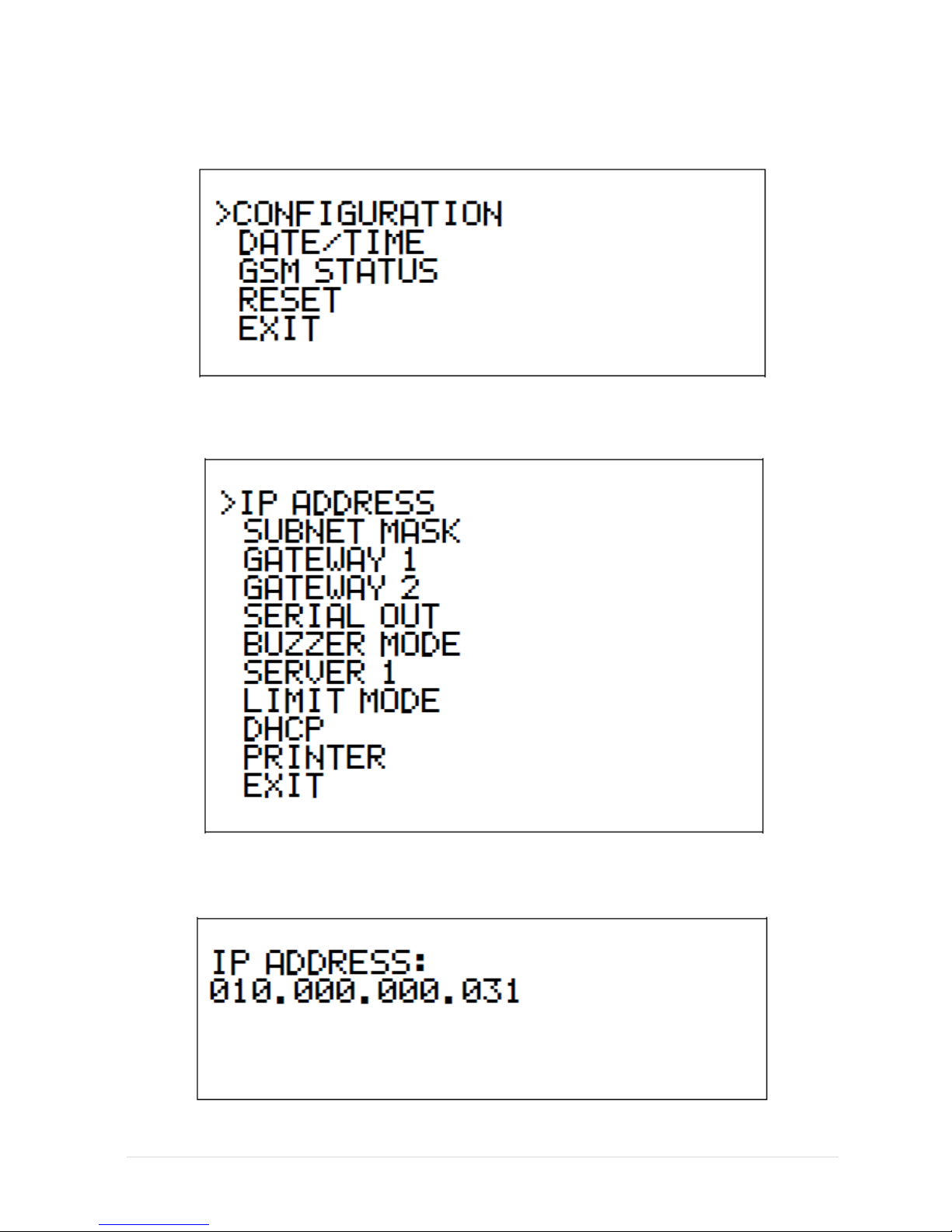
CONFIGURATION
A number of settings on the Router can be changed via the keypad and the LCD.
Be careful when changing settings as you may adversely affect the working of the
Router and its ability to receive and transmit alarms.
1. To change the configuration of the Router, press the ENTER (←) key.
2. The menus can be navigated using the UP (˄) and DOWN (˅) cursors.
3. The ENTER key is used to enter a menu or to enter the data.
Configuration screen
CONFIGURATION MENU – See Below
DATE/TIME
DATE: The date is entered as CCYY/MM/DD
Use the (E) key to advance to the next field
Press ENTER when done
TIME: The time is entered as HH:MM:SS
Use the (E) key to advance to the next field
Press ENTER when done
GSM STATUS
For models fitted with a GSM modem:

6 | P a g e
Press Enter to Display the GSM status:
The GSM status will cycle between the statuses of the two SIM cards installed on
the GSM modem. The Following information is displayed (per SIM card):
DEVICE ID This is the ID of the device on the FSK GSM network
SIG Signal Strength (S0 to S31). Minimum allowable = 20
BER Bit Error Rate (E0 to E99) 0 is optimal 99 is no value obtained
from the network
IP ADDRESS The IP address of this device on the FSK GSM Network
GPRS GPRS connected (GPRS-C) /not connected (GPRS-N)
SIM The status of the SIM card
SIM-OK (SIM card OK)
SIM-ER (SIM Card Error)
STATE Connected State
START (Initialising on GSM network)
READY (connected to FSK routing server)
GSMREG GSM Registration State
GSM-REG (Registered on the GSM network)
GSM-OFF (Not Registered)
GPRSREG Data Registration State
GPRS-REG (Registered on 3G/Edge/GPRS)
GPRS-OFF (Not registered on GSM data)
7 | P a g e
Press the CLEAR button to exit the menu
CONFIGURATION MENU:
Press Enter to access the configuration menu:
IP ADDRESS
The IP address is 10.0.0.31

8 | P a g e
Enter the IP address with leading zeros, e.g. 10 is entered as 010.
Use the (E) key to advance on field.
Press Enter when done.
SUBNET MASK
The Subnet Mask is 255.255.255.0.
Enter the Subnet Mask with leading zeros, e.g. 10 is entered as 010.
Use the (E) key to advance on field.
Press Enter when done.
GATEWAY 1
Gateway 1 is 10.0.0.1.
Enter the Gateway with leading zeros, e.g. 10 is entered as 010.
Use the (E) key to advance on field.
Press Enter when done.
9 | P a g e
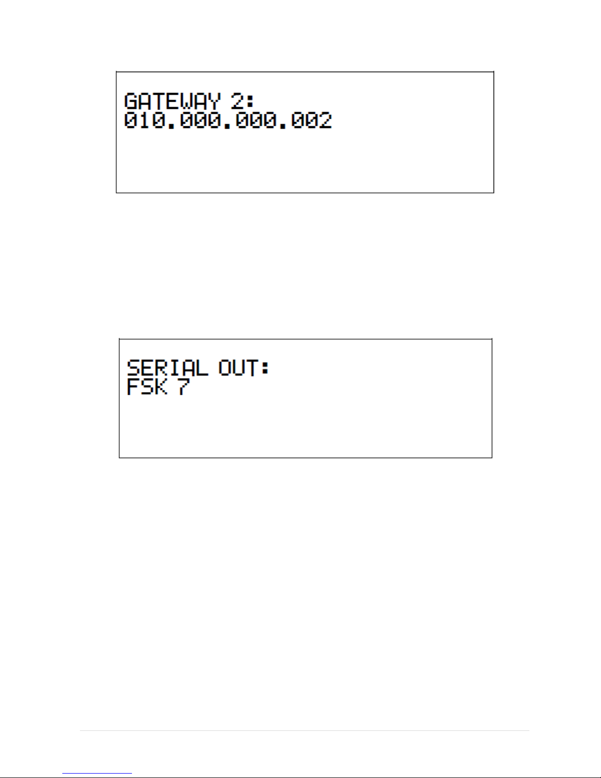
GATEWAY 2
Gateway 2 is 10.0.0.2.
Enter the Gateway with leading zeros, e.g. 10 is entered as 010.
Use the (E) key to advance on field.
Press Enter when done.
SERIAL OUT
The Serial Output format is used to send alarms to the Control Room Computer via
the RS232 port.
Use the UP and DOWN arrows to cycle between the following Serial Output
formats:
FSK 7
FSK
FSK EXTENDED
Refer to Appendix A for the descriptions of the Serial Output formats.
FSK 7 is the preferred Serial Format.
MAKE SURE THAT THE CORRECT SERIAL FORMAT IS SELECTED OR THE
MONITORING COMPUTER WILL NOT RECEIVE ANY ALARMS

10 | P a g e
BUZZER
The buzzer mode can be set to the following:
BUZZER MODE
FUNCTION
BUZZER OFF
The buzzer will not sound when alarms are received
BUZZER ON
The Buzzer will sound when an alarm is received
ON WITH RELAY
When an alarm is received, the Buzzer will turn on briefly
The on-board relay will also turn on (for use with an external
siren)
SUSTAIN WITH
RELAY
When an alarm is received, the Buzzer will turn on and stay on.
The on-board relay will also turn on (for use with an external
siren).
The Buzzer and Relay have to be cancelled by pressing the CLR
key.
Press the UP and DOWN keys to select the required Buzzer operation.
Press ENTER when done.
SERVER 1
Server 1 is 10.0.0.31
Enter the Server address with leading zeros, e.g. 10 is entered as 010
Use the (E) key to advance on field.

11 | P a g e
If the Server IP Address is to be entered as a domain name with letters, do the
following:
Press one of the keys repetitively to select the correct alphabetical
character.
Use the UP and DOWN keys to move between the fields.
Press the (E) key to end the entry (i.e. last character).
Press the ENTER key when done.
KEY
CHARACTER(S)
1
1
2
2 a b c A B C
3
3 d e f D E F
4
4 g h I G H I
5
5 j k l J K L
6
6 m n o M N O
7
7 p q r s P Q R S
8
8 t u v T U V
9
9 w x y z W X Y Z
0
0 /. - , + * ) ( : ; & % $ # “ ! SPACE
*
: ; < = > ? @
(E)
END OF TEXT
Remember to end the Text using the (E) key
LIMIT MODE
The Limit Mode function will restrict the types of alarms which will be sent from the
Router to the Monitoring Computer.
The following limits are used:

12 | P a g e
LIMIT MODE
ALARMS RECEIVED
NONE
All alarms
STRICT
Only panic and Burglary Signals
RECOMMENDED
The recommended list of FSK alarm
codes.
Refer to Appendix B
Limit mode set to NONE is not recommended on older radio networks.
DHCP
The DHCP setting enables or disables DHCP. If DHCP is enabled then the Ethernet
will receive an IP address from the network. If disabled then a static IP must be
entered as per IP address, subnet mask, gateway 1 and gateway 2 settings
described previously on pages 7, 8 and 9.
The following options are available:
DHCP MODE
DHCP ENABLED
ON
DHCP is enabled for the network
OFF
DHCP is not enabled – static IP’s to be used
PRINTER

13 | P a g e
The printer setting enables or disables all signals received to be printed if there is a
printer connected to the router’s printer port.
The following options are available:
PRINTER MODE
ALARMS PRINTED
ON
All alarms printed
OFF
No alarms printed
When all the settings have been changed to the desired ones, go back to the
Configuration Menu. Use the DOWN key to go down to RESET.
Press the ENTER key to save all your new settings.
CHANGED SETTINGS ONLY TAKE EFFECT AFTER A RESET.

14 | P a g e
APPENDIX A - RS232 CONNECTIONS AND PROTOCOL
The Router is fitted with a female DB9 RS232 connector which is used to send
alarms to the monitoring computer.
5
1
9 6
PIN FUNCTION
2 RS232 TXD
3 RS232 RXD
5
GND
5
3
DB9
FEMALE
SERIAL
CABLE
3 25
WIRE LENGTH = 400mm
RXD
2
5 23
5 23
TXD
TXD
RXD
GND (black)
DB9
MALE
DB9 FEMALE CONNECTOR
COMPUTER
FSK STANDARD
BAUD RATE: 1200
Stop Bits: 1
Data Bits: 8
Parity: NONE
Handshaking: NONE
String Format <SOT>
Start of Text ASCII Char 2
ACCOUNT 1-5 Account Code (5 ASCII
characters, e.g. 12345)
INFORMATION 1-3 Alarm Information (3
ASCII characters, e.g.
097)
<CR> Carriage Return (ASCII
character 13)
<LF> Line Feed (ASCII
Character 10)
<EOT> End of Text (ASCII
Character 4)

15 | P a g e
FSK EXTENDED
BAUD RATE: 1200
Stop Bits: 1
Data Bits: 8
Parity: NONE
Handshaking: NONE
String Format <SOT>
Start of Text ASCII Char 2
ACCOUNT 1-5 Account Code (5 ASCII
characters, e.g. 12345)
INFORMATION 1-3 Alarm Information (3
ASCII characters, e.g.
097)
REPEATER 1-2 Repeater Number (2
ASCII characters, e.g.
01)
Repeater is set to 31 if
the signal is received
directly
RSSI Relative Signal Strength
Indicator
ASCII character 0 to 7 (0 =
weakest, 7 = Strongest)
<CR> Carriage Return (ASCII
character 13)
<LF> Line Feed (ASCII
Character 10)
<EOT> End of Text (ASCII
Character 4)
FSK7 (CONTACT ID)
Baud: 9600
Parity: none
Stop bits: 1
Data bits: 8
Handshaking: none
Base to PC (spaces for readability only)
$02 T AAAAA Q CCC PP ZZZ S RR I I NFF $0D
$02 -Start of text 2 hex.
T -Message type (ASCII) ‘C’ *
AAAAA -5 digit account code (ASCII)
Q -Qualifier E, R, S (ASCII) **
CCC -Alarm code 000 to 999 (ASCII)
PP -Partition 00 to 99 (ASCII)
ZZZ -Zone or user 000 to 999 (ASCII)
S -Start code 0 to 7 (ASCII)
RR -Repeater ID 00 to 32 (ASCII)
I -RSSI Local 0 to 7 (ASCII)
(Repeater)
I -RSSI Remote 0 to 7 (ASCII)
(Transmitter)
N - Line Card or slot number A = Line
Card 0, I = Line Card 8
FF -Free space = 00 (ASCII)
$0D -Carriage Return 13 decimal.
* T Only one message type ‘C’ in use. The
ASCII character C means that the alarm
codes (CCC) correspond to the ADEMCO 18
contact ID alarm codes. The alarm codes are
defined in the SIA-05-1999.09 document.
** Q Event qualifier: E = new event, R =
event restore, S = status report.
***N Line Card or Slot.
Identifies the Line Card (slot) from which the
alarm comes in the Multi-Router.
Slot 0 is sent as ‘A’, slot 8 is sent as ‘I’
Slot 0 is for local messages from router (e.g.
heartbeat, power-up etc.)
Slots 1 to 8 are used to identify the receiver
which received the signal.

16 | P a g e
APPENDIX B - FSK ALARM CODES
The Router 0211 is capable of receiving either FSK Alarms or Contact ID Alarms.
If the format of the alarm received is not the same as the serial port protocol selected
(see Appendix A) the Router 0211 will convert from the one format to the other.
For example, if an alarm is received in the FSK format and the RS232 format is set to FSK7
(Contact ID), the Router 0211 will convert the FSK format alarm to its Contact ID
equivalent.
If an alarm is received in Contact ID format and the RS232 protocol is set to FSK , the
Router 0211 will attempt to convert the alarm to the equivalent FSK code.
Note that not all Contact ID codes have an equivalent FSK code.
TABLE B1: FSK ALARM CODES AND EQUIVALENT CONTACT ID CONVERSION
FSK
FSK
FSK
CONTACT ID
PTY
LIMIT
CODE
DESCRIPTION
ALTERNATE
USE
CODE
E
DESCRIPTION
ZONE
ALARM
TELEM
R
0
AUTO TEST
602 E Periodic test report Zone
0
NO
YES 1 CANCEL BY KEYH 1
406 E Cancel User
1
NO
NO 2 TELEMETRY 2
COMMS
RESTORED
357 E Long Range Radio
2
NO
NO 3 TELEMETRY 3
603 E Periodic RF Test
3
NO
NO 4 POINTS MISSED
708 E POINTS MISSED
0
NO
NO
5
PATROL START LATE
703 E PATROL START LATE
0
NO
NO
6
PATROL START ON
TIME
702 E PATROL START
0
NO
NO 7 GUARD PATROL SLOW
711 E GUARD PATROL SLOW
0
NO
NO 8 GUARD PATROL FAST
712 E GUARD PATROL FAST
0
NO
NO
9
GUARD FAIL TO START
SHIFT
716 E GUARD FAIL TO START SHIFT
0
NO
NO
10
PROGRAM COMPLETE
628 E Program Mode Exit
0
NO
NO
11
GUARD LATE ON DUTY
707 E GUARD LATE ON DUTY
0
NO
NO
12
WRONG ROUTE
718 E WRONG ROUTE
0
NO
NO
13
SUPERVISOR ON SITE
140 E Supervisor on site
13
NO
NO
14
SUPERVISOR OFF SITE
140 R Supervisor on site
14
NO
NO
15
OPEN KEYH 99
409 E Keyswitch O/C
99
NO
NO
16
ELECTRIC FENCE
131 E Perimeter Zone
0
NO
YES
17
WATCHDOG RESET
305 E System reset Zone
0
NO
NO
18
LOOP TROUBLE RES
332 R Polling loop short Zone
0
NO
NO
19
SIREN FUSE RESTORE
321 R Bell 1
0
NO
NO
20
FAIL TO REPORT
350 E Communication trouble
0
NO
NO

17 | P a g e
Zone
21
LOOP TROUBLE
141 E Polling loop open Zone
0
NO
NO
22
SIREN FUSE FAIL
321 E Bell 1
0
NO
NO
23
EMERGENCY
101 E Personal Emergency Zone
0
YES
YES
24
REMOTE PANIC
101 E Personal Emergency Zone
0
YES
YES
25
PANIC
120 E Panic Zone
0
YES
YES
26
DURESS
121 E Duress User
0
YES
YES
27
BATT VOLTAGE LOW
302 E Low system battery Zone
0
NO
YES
28
BATT VOLTAGE REST
302 R Low system battery Zone
0
NO
YES
29
AC POWER FAIL
301 E AC Loss Zone
0
NO
YES
30
AC POWER RESTORED
301 R AC Loss Zone
0
NO
YES
31
TRASNMTR LOCKED
ON 353
E
Long Range Radio emitter
fault Zone
0
NO
YES
32
HOLD UP
121 E Duress User
0
NO
YES
33
OPEN BY KEYH 1
GUARD ON
DUTY
400 E Open/Close User
1
NO
YES
34
OPEN BY KEYH 2
400 E Open/Close User
2
NO
NO
35
OPEN BY KEYH 3
400 E Open/Close User
3
NO
NO
36
OPEN BY KEYH 4
400 E Open/Close User
4
NO
NO
37
OPEN BY KEYH 5
400 E Open/Close User
5
NO
NO
38
OPEN BY KEYH 6
400 E Open/Close User
6
NO
NO
39
OPEN BY KEYH 7
400 E Open/Close User
7
NO
NO
40
OPEN BY KEYH 8
400 E Open/Close User
8
NO
NO
41
OPEN BY KEYH 9
400 E Open/Close User
9
NO
NO
42
OPEN BY KEYH 10
400 E Open/Close User
10
NO
NO
43
OPEN BY KEYH 11
400 E Open/Close User
11
NO
NO
44
OPEN BY KEYH 12
400 E Open/Close User
12
NO
NO
45
OPEN BY KEYH 13
400 E Open/Close User
13
NO
NO
46
OPEN BY KEYH 14
400 E Open/Close User
14
NO
NO
47
OPEN BY KEYH 15
400 E Open/Close User
15
NO
NO
48
OPEN BY KEYH 16
400 E Open/Close User
16
NO
NO
49
OPEN BY KEYH 17
400 E Open/Close User
17
NO
NO
50
OPEN BY KEYH 18
400 E Open/Close User
18
NO
NO
51
OPEN BY KEYH 19
400 E Open/Close User
19
NO
NO
52
OPEN BY KEYH 20
400 E Open/Close User
20
NO
NO
53
PARTIAL ARM
456 R Partial Arm
0
NO
NO
54
MANUAL TEST
601
E
Manual trigger test report
Zone
0
NO
NO
55
PROGRAM COMPLETE
628 E Program mode exit Zone
0
NO
NO
56
PERIPHERAL TROUBLE
330
E
System Peripheral trouble
Zone
0
NO
NO
57
COMS TROUBLE
350
E
Communication trouble
Zone
0
NO
NO
58
PERIODIC TEST
602 E Periodic test report Zone
0
NO
NO
59
TELEMETRY 59
603 E Periodic RF Transmission
59
NO
NO
60
TELEMETRY 60
603 E Periodic RF Transmission
60
NO
NO
61
TELEMETRY 61
603 E Periodic RF Transmission
61
NO
NO

18 | P a g e
62
TELEMETRY 62
603 E Periodic RF Transmission
62
NO
NO
63
TELEMETRY 63
603 E Periodic RF Transmission
63
NO
NO
64
TELEMETRY 64
603 E Periodic RF Transmission
64
NO
NO
65
CLOSE BY KEYH 1
GUARD OFF
DUTY
400 R Open/Close User
1
NO
YES
66
CLOSE BY KEYH 2
400 R Open/Close User
2
NO
NO
67
CLOSE BY KEYH 3
400 R Open/Close User
3
NO
NO
68
CLOSE BY KEYH 4
400 R Open/Close User
4
NO
NO
69
CLOSE BY KEYH 5
400 R Open/Close User
5
NO
NO
70
CLOSE BY KEYH 6
400 R Open/Close User
6
NO
NO
71
CLOSE BY KEYH 7
400 R Open/Close User
7
NO
NO
72
CLOSE BY KEYH 8
400 R Open/Close User
8
NO
NO
73
CLOSE BY KEYH 9
400 R Open/Close User
9
NO
NO
74
CLOSE BY KEYH 10
400 R Open/Close User
10
NO
NO
75
CLOSE BY KEYH 11
400 R Open/Close User
11
NO
NO
76
CLOSE BY KEYH 12
400 R Open/Close User
12
NO
NO
77
CLOSE BY KEYH 13
400 R Open/Close User
13
NO
NO
78
CLOSE BY KEYH 14
400 R Open/Close User
14
NO
NO
79
CLOSE BY KEYH 15
400 R Open/Close User
15
NO
NO
80
CLOSE BY KEYH 16
400 R Open/Close User
16
NO
NO
81
CLOSE BY KEYH 17
400 R Open/Close User
17
NO
NO
82
CLOSE BY KEYH 18
400 R Open/Close User
18
NO
NO
83
CLOSE BY KEYH 19
400 R Open/Close User
19
NO
NO
84
CLOSE BY KEYH 20
400 R Open/Close User
20
NO
NO
85
TELEMETRY 85
140 E General Alarm Zone
85
NO
NO
86
PRINTER OFF-LINE
336 E Local printer failure Zone
0
NO
YES
87
RAM OR I/O ERROR
303 E RAM Checksum bad Zone
0
NO
YES
88
SYS TEST BY CNTR
601
E
Manual trigger test report
Zone
0
NO
NO
89
CLOSE BY KEYH 99
409 R Keyswitch O/C User
99
NO
NO
90
TELEMETRY 90
603 E Periodic RF Transmission
90
NO
NO
91
TELEMETRY 91
603 E Periodic RF Transmission
91
NO
NO
92
TELEMETRY 92
603 E Periodic RF Transmission
92
NO
NO
93
TELEMETRY 93
603 E Periodic RF Transmission
93
NO
NO
94
TELEMETRY 94
603 E Periodic RF Transmission
94
NO
NO
95
TELEMETRY 95
603 E Periodic RF Transmission
95
NO
NO
96
TELEMETRY 96
603 E Periodic RF Transmission
96
NO
NO
97
BURGLARY ZONE 1
130 E Burglary Zone
1
YES
YES
98
BURGLARY ZONE 2
130 E Burglary Zone
2
YES
YES
99
BURGLARY ZONE 3
130 E Burglary Zone
3
YES
NO
100
BURGLARY ZONE 4
130 E Burglary Zone
4
YES
NO
101
BURGLARY ZONE 5
130 E Burglary Zone
5
YES
NO
102
BURGLARY ZONE 6
130 E Burglary Zone
6
YES
NO
103
BURGLARY ZONE 7
130 E Burglary Zone
7
YES
NO
104
BURGLARY ZONE 8
130 E Burglary Zone
8
YES
NO

19 | P a g e
105
BURGLARY ZONE 9
130 E Burglary Zone
9
YES
NO
106
BURGLARY ZONE 10
130 E Burglary Zone
10
YES
NO
107
BURGLARY ZONE 11
130 E Burglary Zone
11
YES
NO
108
BURGLARY ZONE 12
130 E Burglary Zone
12
YES
NO
109
BURGLARY ZONE 13
130 E Burglary Zone
13
YES
NO
110
BURGLARY ZONE 14
130 E Burglary Zone
14
YES
NO
111
BURGLARY ZONE 15
130 E Burglary Zone
15
YES
NO
112
BURGLARY ZONE 16
130 E Burglary Zone
16
YES
NO
113
BURGLARY ZONE 17
130 E Burglary Zone
17
YES
NO
114
BURGLARY ZONE 18
130 E Burglary Zone
18
YES
NO
115
BURGLARY ZONE 19
130 E Burglary Zone
19
YES
NO
116
BURGLARY ZONE 20
130 E Burglary Zone
20
YES
NO
117
BURGLARY ZONE 21
130 E Burglary Zone
21
YES
NO
118
BURGLARY ZONE 22
130 E Burglary Zone
22
YES
NO
119
BURGLARY ZONE 23
130 E Burglary Zone
23
YES
NO
120
BURGLARY ZONE 24
130 E Burglary Zone
24
YES
NO
121
BURGLARY ZONE 25
130 E Burglary Zone
25
YES
NO
122
BURGLARY ZONE 26
130 E Burglary Zone
26
YES
NO
123
BURGLARY ZONE 27
130 E Burglary Zone
27
YES
NO
124
BURGLARY ZONE 28
130 E Burglary Zone
28
YES
NO
125
BURGLARY ZONE 29
130 E Burglary Zone
29
YES
NO
126
BURGLARY ZONE 30
130 E Burglary Zone
30
YES
NO
127
BURGLARY ZONE 31
130 E Burglary Zone
31
YES
NO
128
BURGLARY ZONE 32
130 E Burglary Zone
32
YES
NO
129
ISOLATE ZONE 1
570 E Zone/Sensor bypass Zone
1
NO
NO
130
ISOLATE ZONE 2
570 E Zone/Sensor bypass Zone
2
NO
NO
131
ISOLATE ZONE 3
570 E Zone/Sensor bypass Zone
3
NO
NO
132
ISOLATE ZONE 4
570 E Zone/Sensor bypass Zone
4
NO
NO
133
ISOLATE ZONE 5
570 E Zone/Sensor bypass Zone
5
NO
NO
134
ISOLATE ZONE 6
570 E Zone/Sensor bypass Zone
6
NO
NO
135
ISOLATE ZONE 7
570 E Zone/Sensor bypass Zone
7
NO
NO
136
ISOLATE ZONE 8
570 E Zone/Sensor bypass Zone
8
NO
NO
137
ISOLATE ZONE 9
570 E Zone/Sensor bypass Zone
9
NO
NO
138
ISOLATE ZONE 10
570 E Zone/Sensor bypass Zone
10
NO
NO
139
ISOLATE ZONE 11
570 E Zone/Sensor bypass Zone
11
NO
NO
140
ISOLATE ZONE 12
570 E Zone/Sensor bypass Zone
12
NO
NO
141
ISOLATE ZONE 13
570 E Zone/Sensor bypass Zone
13
NO
NO
142
ISOLATE ZONE 14
570 E Zone/Sensor bypass Zone
14
NO
NO
143
ISOLATE ZONE 15
570 E Zone/Sensor bypass Zone
15
NO
NO
144
ISOLATE ZONE 16
570 E Zone/Sensor bypass Zone
16
NO
NO
145
ISOLATE ZONE 17
570 E Zone/Sensor bypass Zone
17
NO
NO
146
ISOLATE ZONE 18
570 E Zone/Sensor bypass Zone
18
NO
NO
147
ISOLATE ZONE 19
570 E Zone/Sensor bypass Zone
19
NO
NO
148
ISOLATE ZONE 20
570 E Zone/Sensor bypass Zone
20
NO
NO

20 | P a g e
149
ISOLATE ZONE 21
570 E Zone/Sensor bypass Zone
21
NO
NO
150
ISOLATE ZONE 22
570 E Zone/Sensor bypass Zone
22
NO
NO
151
ISOLATE ZONE 23
570 E Zone/Sensor bypass Zone
23
NO
NO
152
ISOLATE ZONE 24
570 E Zone/Sensor bypass Zone
24
NO
NO
153
GUARD FIRE
110 E Fire 0 NO
NO
154
ASSISTANCE
REQUIRED
704 E ASSISTANCE REQUIRED
0
NO
NO
155
GUARD PATROL FAIL
705 E GUARD PATROL FAIL
0
NO
YES
156
GUARD SYSTEM ON
715 E GUARD SYSTEM ON
0
NO
YES
157
GUARD SYSTEM OFF
714 E GUARD SYSTEM OFF
0
NO
YES
158
GUARD TAMPER
137 E Tamper
0
NO
NO
159
FAIL TO START PATROL
701 E FAIL TO START PATROL
0
NO
NO
160
GUARD PATROL COMP
713 E GUARD PATROL COMP
0
NO
YES
161
RESTORAL ZONE 1
130 R Burglary Zone
1
NO
NO
162
RESTORAL ZONE 2
130 R Burglary Zone
2
NO
NO
163
RESTORAL ZONE 3
130 R Burglary Zone
3
NO
NO
164
RESTORAL ZONE 4
130 R Burglary Zone
4
NO
NO
165
RESTORAL ZONE 5
130 R Burglary Zone
5
NO
NO
166
RESTORAL ZONE 6
130 R Burglary Zone
6
NO
NO
167
RESTORAL ZONE 7
130 R Burglary Zone
7
NO
NO
168
RESTORAL ZONE 8
130 R Burglary Zone
8
NO
NO
169
RESTORAL ZONE 9
130 R Burglary Zone
9
NO
NO
170
RESTORAL ZONE 10
130 R Burglary Zone
10
NO
NO
171
RESTORAL ZONE 11
130 R Burglary Zone
11
NO
NO
172
RESTORAL ZONE 12
130 R Burglary Zone
12
NO
NO
173
RESTORAL ZONE 13
130 R Burglary Zone
13
NO
NO
174
RESTORAL ZONE 14
130 R Burglary Zone
14
NO
NO
175
RESTORAL ZONE 15
130 R Burglary Zone
15
NO
NO
176
RESTORAL ZONE 16
130 R Burglary Zone
16
NO
NO
177
RESTORAL ZONE 17
130 R Burglary Zone
17
NO
NO
178
RESTORAL ZONE 18
130 R Burglary Zone
18
NO
NO
179
RESTORAL ZONE 19
130 R Burglary Zone
19
NO
NO
180
RESTORAL ZONE 20
130 R Burglary Zone
20
NO
NO
181
RESTORAL ZONE 21
130 R Burglary Zone
21
NO
NO
182
RESTORAL ZONE 22
130 R Burglary Zone
22
NO
NO
183
RESTORAL ZONE 23
130 R Burglary Zone
23
NO
NO
184
RESTORAL ZONE 24
130 R Burglary Zone
24
NO
NO
185
RESTORAL ZONE 25
130 R Burglary Zone
25
NO
NO
186
KEYPAD PANIC
120 E Panic Zone
0
NO
NO
187
KEYPAD TAMPER
137 E Tamper Zone
0
NO
NO
188
EPROM ERROR
304 E ROM checksum bad Zone
0
NO
NO
189
SYSTEM TROUBLE
300 E System Trouble Zone
0
NO
NO
190
FIRE SYSTEM TEST
604 E Fire test User
0
NO
NO
191
FIRE SUPERVISORY
200 E Fire Supervisory Zone
0
NO
NO
192
TELEMETRY 192
140 E General Alarm
192
NO
NO

21 | P a g e
193
FIRE ZONE 1
110 E Fire Zone
1
NO
YES
194
ISOLATE ZONE 25
570 E Zone/Sensor bypass Zone
25
NO
NO
195
ISOLATE ZONE 26
570 E Zone/Sensor bypass Zone
26
NO
NO
196
ISOLATE ZONE 27
570 E Zone/Sensor bypass Zone
27
NO
NO
197
ISOLATE ZONE 28
570 E Zone/Sensor bypass Zone
28
NO
NO
198
ISOLATE ZONE 29
570 E Zone/Sensor bypass Zone
29
NO
NO
199
ISOLATE ZONE 30
570 E Zone/Sensor bypass Zone
30
NO
NO
200
ISOLATE ZONE 31
570 E Zone/Sensor bypass Zone
31
NO
NO
201
ISOLATE ZONE 32
570 E Zone/Sensor bypass Zone
32
NO
NO
202
RESTORAL ZONE 26
130 R Burglary Zone
26
NO
NO
203
RESTORAL ZONE 27
130 R Burglary Zone
27
NO
NO
204
RESTORAL ZONE 28
130 R Burglary Zone
28
NO
NO
205
RESTORAL ZONE 29
130 R Burglary Zone
29
NO
NO
206
RESTORAL ZONE 30
130 R Burglary Zone
30
NO
NO
207
RESTORAL ZONE 31
130 R Burglary Zone
31
NO
NO
208
RESTORAL ZONE 32
130 R Burglary Zone
32
NO
NO
209
FAULT ZONE 25
380 E Sensor trouble Zone
25
NO
NO
210
FAULT ZONE 26
380 E Sensor trouble Zone
26
NO
NO
211
FAULT ZONE 27
380 E Sensor trouble Zone
27
NO
NO
212
FAULT ZONE 28
380 E Sensor trouble Zone
28
NO
NO
213
FAULT ZONE 29
380 E Sensor trouble Zone
29
NO
NO
214
FAULT ZONE 30
380 E Sensor trouble Zone
30
NO
NO
215
FAULT ZONE 31
380 E Sensor trouble Zone
31
NO
NO
216
FAULT ZONE 32
380 E Sensor trouble Zone
32
NO
NO
217
DELAYED ALARM
130 E Burglary Zone
3
YES
YES
218
AUXILIARY ALARM
140 E General Alarm Zone
0
NO
NO
219
BELL TROUBLE
320 E Sounder/Relay Zone
0
NO
NO
220
BELL TROUBLE
RESTORE
320 R Sounder/Relay Zone
0
NO
NO
221
TIMER TEST
602 E Periodic test report Zone
0
NO
NO
222
GENERAL ALARM
140 E General Alarm
0
NO
NO
223
UNWANTED CARRIER
344 E RF Receiver Jam Detect Zone
0
NO
YES
224
MEDICAL EMERGENCY
100 E Medical Zone
0
NO
YES
225
FAULT ZONE 1
380 E Sensor trouble Zone
1
NO
NO
226
FAULT ZONE 2
380 E Sensor trouble Zone
2
NO
NO
227
FAULT ZONE 3
380 E Sensor trouble Zone
3
NO
NO
228
FAULT ZONE 4
380 E Sensor trouble Zone
4
NO
NO
229
FAULT ZONE 5
380 E Sensor trouble Zone
5
NO
NO
230
FAULT ZONE 6
380 E Sensor trouble Zone
6
NO
NO
231
FAULT ZONE 7
380 E Sensor trouble Zone
7
NO
NO
232
FAULT ZONE 8
380 E Sensor trouble Zone
8
NO
NO
233
FAULT ZONE 9
380 E Sensor trouble Zone
9
NO
NO
234
FAULT ZONE 10
380 E Sensor trouble Zone
10
NO
NO
235
FAULT ZONE 11
380 E Sensor trouble Zone
11
NO
NO
236
FAULT ZONE 12
380 E Sensor trouble Zone
12
NO
NO

22 | P a g e
237
FAULT ZONE 13
380 E Sensor trouble Zone
13
NO
NO
238
FAULT ZONE 14
380 E Sensor trouble Zone
14
NO
NO
239
FAULT ZONE 15
380 E Sensor trouble Zone
15
NO
NO
240
FAULT ZONE 16
380 E Sensor trouble Zone
16
NO
NO
241
FAULT ZONE 17
380 E Sensor trouble Zone
17
NO
NO
242
FAULT ZONE 18
380 E Sensor trouble Zone
18
NO
NO
243
FAULT ZONE 19
380 E Sensor trouble Zone
19
NO
NO
244
FAULT ZONE 20
380 E Sensor trouble Zone
20
NO
NO
245
FAULT ZONE 21
380 E Sensor trouble Zone
21
NO
NO
246
FAULT ZONE 22
380 E Sensor trouble Zone
22
NO
NO
247
FAULT ZONE 23
380 E Sensor trouble Zone
23
NO
NO
248
FAULT ZONE 24
380 E Sensor trouble Zone
24
NO
NO
249
TAMPER
137 E Tamper Zone
0
NO
NO
250
POWER UP
301 R AC Loss Zone
0
NO
YES
251
SYSTEM COMMAND 2
603 E Periodic RF Transmission
251
NO
NO
252
GPRS FAILED
350 E Comms Trouble
252
NO
NO
253
GPRS RESTORED
350 R Comms Trouble
253
NO
NO
254
NOT USED
MINIBASE
STUNNED
140 E General Alarm
254
NO
NO
RED - NON STANDARD
TABLE B2 - ADEMCO CODES TO FSK CODES CONVERSIONS
When the Router 0211 receives an Ademco Contact ID format alarm and the RS232
format is set to FSK or FSK Extended, the alarm is converted to the equivalent FSK format
alarm.
ADEMCO
CODE
ADEMCO DESCRIPTION
FSK CODE
ON
EVENT
DESCRIPTION
FSK CODE ON
RESTORAL
DESCRIPTION
100
MEDICAL
224
MEDICAL EMERGENCY
101
PERSONAL EMERGENCY
24
REMOTE PANIC
110
FIRE
193
FIRE ZONE 1
111
SMOKE
193
FIRE ZONE 1
112
COMBUSTION
193
FIRE ZONE 1
113
WATER FLOW
193
FIRE ZONE 1
114
HEAT
193
FIRE ZONE 1
115
PULL STATION
193
FIRE ZONE 1
116
DUCT
193
FIRE ZONE 1
117
FLAME
193
FIRE ZONE 1
118
NEAR ALARM
97-128
BURG ZONE 1 TO 32
161-185,202-208
RESTORAL ZONE 124, 26-32
120
PANIC
25
PANIC
121
DURESS
26
DURESS
122
SILENT
25
PANIC
123
AUDIBLE
25
PANIC
130
BURGLARY
97-128
BURG ZONE 1 TO 32
161-185,202-208
RESTORAL ZONE 124, 26-32

23 | P a g e
131
PERIMETER
97-128
BURG ZONE 1 TO 32
161-185,202-208
RESTORAL ZONE 124, 26-32
132
INTERIOR
97-128
BURG ZONE 1 TO 32
161-185,202-208
RESTORAL ZONE 124, 26-32
133
24 HR (SAFE)
97-128
BURG ZONE 1 TO 32
161-185,202-208
RESTORAL ZONE 124, 26-32
134
ENTRY/EXIT
97-128
BURG ZONE 1 TO 32
161-185,202-208
RESTORAL ZONE 124, 26-32
135
DAY/NIGHT
97-128
BURG ZONE 1 TO 32
161-185,202-208
RESTORAL ZONE 124, 26-32
136
OUTDOOR
97-128
BURG ZONE 1 TO 32
161-185,202-208
RESTORAL ZONE 124, 26-32
137
TAMPER
249
TAMPER
138
NEAR ALARM
97-128
BURG ZONE 1 TO 32
161-185,202-208
RESTORAL ZONE 124, 26-32
140
GENERAL ALARM
222
GENERAL ALARM
141
POLLING LOOP OPEN
21
LOOP TROUBLE
142
POLLING LOOP SHORT
21
LOOP TROUBLE
144
SENSOR TAMPER
225-248,
209-216
FAULT ZONE 1-24, 2532
155
FOIL BREAK
189
SYSTEM TROUBLE
156
DAY TROUBLE
189
SYSTEM TROUBLE
200
FIRE SUPERVISORY
191
FIRE SUPERVISORY
201
LOW WATER PRESSIURE
191
FIRE SUPERVISORY
202
LOW CO2
191
FIRE SUPERVISORY
203
GATE VALVE SENSOR
191
FIRE SUPERVISORY
205
PUMP ACTIVATED
191
FIRE SUPERVISORY
206
PUMP FAILURE
191
FIRE SUPERVISORY
300
SYSTEM TROUBLE
189
SYSTEM TROUBLE
301
AC LOSS
29
AC POWER FAIL
30
AC POWER
RESTORED
302
LOW SYSTEM BATTERY
27
BATT VOLTAGE LOW
303
RAM CHECKSUM BAD
87
RAM OR I/O ERROR
304
ROM CHECKSUM BAD
87
RAM OR I/O ERROR
305
SYSTEM RESET
189
SYSTEM TROUBLE
306
PANEL PROGRAMMING CHANGED
50
OPEN BY K/H 18
307
SELF-TEST FAILURE
189
SYSTEM TROUBLE
308
SYSTEM SHUTDOWN
189
SYSTEM TROUBLE
309
BATTERY TEST FAILURE
189
SYSTEM TROUBLE
310
GROUND FAULT
189
SYSTEM TROUBLE
320
SOUNDER/RELAY
219
BELL TROUBLE
220
BELL TROUBLE
RESTORE
321
BELL 1
219
BELL TROUBLE
220
BELL TROUBLE
RESTORE
322
BELL 2
219
BELL TROUBLE
220
BELL TROUBLE
RESTORE
324
TROUBLE RELAY
219
BELL TROUBLE
220
BELL TROUBLE
RESTORE
325
REVERSING RELAY
219
BELL TROUBLE
220
BELL TROUBLE
RESTORE
330
SYSTEM PERIPHERAL TROUBLE
56
PERIPHERAL TROUBLE
331
POLLING LOOP OPEN
56
PERIPHERAL TROUBLE

24 | P a g e
332
POLLING LOOP SHORT
56
PERIPHERAL TROUBLE
333
EXPANSION MODULE FAILURE
56
PERIPHERAL TROUBLE
334
REPEATER FAILURE
56
PERIPHERAL TROUBLE
335
LOCAL PRINTER OUT OF PAPER
56
PERIPHERAL TROUBLE
336
LOCAL PRINTER FAILURE
56
PERIPHERAL TROUBLE
350
COMMUNICATIONS TROUBLE
57
COMS TROUBLE
2
TELEMETRY 2
351
TELCO FAULT 1
57
COMS TROUBLE
352
TELCO FAULT 2
57
COMS TROUBLE
353
LONG RANGE RADIO TX FAULT
57
COMS TROUBLE
354
FAILURE TO COMMUNICATE
EVENT
57
COMS TROUBLE
355
LOSS OF RADIO SUPERVISION
57
COMS TROUBLE
356
LOSS OF CENTRAL POLLING
57
COMS TROUBLE
370
PROTECTION LOOP
189
SYSTEM TROUBLE
371
PROTECTION LOOP OPEN
189
SYSTEM TROUBLE
372
PROTECTION LOOP SHORT
189
SYSTEM TROUBLE
373
FIRE TROUBLE
189
SYSTEM TROUBLE
380
SENSOR TROUBLE
225
FAULT ZONE 1
381
LOSS OF SUPERVISION-RF
189
SYSTEM TROUBLE
382
LOSS OF SUPERVISION-RPM
189
SYSTEM TROUBLE
383
SENSOR TAMPER
225
FAULT ZONE 1
384
RF LOW BATTERY
189
SYSTEM TROUBLE
400
OPEN/CLOSE
33-52
OPEN BY K/H 1-20
65-84
CLOSE BY K/H 1-20
401
O/C BY USER
33-52
OPEN BY K/H 1-20
65-84
CLOSE BY K/H 1-20
402
GROUP O/C
33-52
OPEN BY K/H 1-20
65-84
CLOSE BY K/H 1-20
403
AUTOMATIC O/C
33-52
OPEN BY K/H 1-20
65-84
CLOSE BY K/H 1-20
405
DEFERRED O/C
33-52
OPEN BY K/H 1-20
65-84
CLOSE BY K/H 1-20
406
CANCEL
1
CANCEL BY K/H 1
407
REMOTE ARM/DISARM
49
OPEN BY K/H 17
81
CLOSE BY K/H 17
408
QUICK ARM
51
OPEN BY K/H 19
83
CLOSE BY K/H 19
409
KEYSWITCH O/C
15
TELEMETRY 15/OPEN
K/H 99
89
CLOSE BY K/H 99
456
PARTIAL ARM
53
PARTIAL ARM
551
DIALLER DISABLED
52
OPEN BY K/H 20
552
RADIO TRANSMITTER DISABLED
52
OPEN BY K/H 20
570
ZONE/SENSOR BYPASS
129-152,
194-201
ISOLATE ZONE 1-24,
25-32
161-185,202-208
RESTORAL ZONE 124, 26-32
571
FIRE BYPASS
129-152,
194-201
ISOLATE ZONE 1-24,
25-32
161-185,202-208
RESTORAL ZONE 124, 26-32
572
24 HOUR ZONE BYPASS
129-152,
194-201
ISOLATE ZONE 1-24,
25-32
161-185,202-208
RESTORAL ZONE 124, 26-32
573
BURG. BYPASS
129-152,
194-201
ISOLATE ZONE 1-24,
25-32
161-185,202-208
RESTORAL ZONE 124, 26-32
574
GROUP BYPASS
129-152,
194-201
ISOLATE ZONE 1-24,
25-32
161-185,202-208
RESTORAL ZONE 124, 26-32
601
MANUAL TEST TRIGGER REPORT
54
MANUAL TEST
602
PERIODIC TEST REPORT
58
PERIODIC TEST

25 | P a g e
604
FIRE TEST
190
FIRE YSTEM TEST
627
PROGRAM MODE ENTRY
55
PROGRAM COMPLETE
55
PROGRAM
COMPLETE
628
PROGRAM MODE EXIT
55
PROGRAM COMPLETE
55
PROGRAM
COMPLETE
NONSTANDARD
FOR GMU
NOT
SENT BY
TX75X
701
Guard fail to start timer (patrol
lead time)
159
GUARD FAIL TO START
PATROL
702
Patrol start tag
6
TELE 6/ PATROL START
ON TIME
703
Patrol start tag late
5
PATROL START LATE
704
Guard requested assistance
154
ASSISTANCE
REQUIRED
705
Guard fail to return timer
155
GUARD PATROL FAIL
706
Guard late return tag
160
GUARD PATROL
COMPLETE
707
Guard late on duty
11
GUARD LATE ON DUTY
708
Points read, points missed
4
POINTS MISSED
709
Points read points slow
7
GUARD PATROL SLOW
710
Points read points fast
8
GUARD PATROL FAST
711
Points read Overall walk slow
7
GUARD PATROL SLOW
712
Points read Overall walk fast
8
GUARD PATROL FAST
713
Points read points OK
160
GUARD PATROL
COMPLETE
714
Guard off duty
157
GUARD SYSTEM OFF
715
Guard on duty
156
GUARD SYSTEM ON
716
Guard off duty timer
9
GUARD FAIL TO START
SHIFT
717
SUPERVISOR ON DUTY
13
SUPERVISOR ON SITE
14
SUPERVISOR OFF
SITE
718
Power up
13
SUPERVISOR ON SITE
719
GUARD SYSTEM POWER-UP
250
POWER UP

26 | P a g e
APPENDIX C - PRINTER CONNECTIONS
PRINTER - DB25 FEMALE ON ROUTER 0211
113
1425
DB25 FEMALE FRONT VIEW
PIN NO
NAME
FUNCTION
1
STROBE
STROBE PRINTER
2
DO
PRINTER DATA 0
3
D1
PRINTER DATA 1
4
D2
PRINTER DATA 2
5
D3
PRINTER DATA 3
6
D4
PRINTER DATA 4
7
D5
PRINTER DATA 5
8
D6
PRINTER DATA 6
9
D7
PRINTER DATA 7
10
PACK
PRINTER ACKNOWLEDGE
11
PBUSY
PRINTER BUSY
12
POUT
PAPER OUT
13
PSEL
PRINTER SELECT
14
15
PERR
PRINTER ERROR
16
PINIT
PRINTER INITIALISE
17
PSELPRN
PRINTER SELECTED
18-25
GND
GROUND

27 | P a g e
APPENDIX D - ROUTER SPECIFICATIONS
Receiver Radio Specifications
Radio Performance tested to : ETSI 300-086
EMI Tested to : ETSI EN 301
Safety to : EN 60 950
Mode of Operation : FM
Channel Spacing : 12,5kHz
Frequency of Operation : 135 to 175MHz
Frequency Error : <1 kHz (0 to 55 °C)
Spurious Conducted Components : < -56 dBm (9 kHz to 1GHz)
< -50 dBm (1GHz to 4GHz)
Adjacent Channel Selectivity : < -70dB
Intermodulation : <-70dB (ETSI)
Antenna : PL259 (UHF) 50Ω
Sensitivity (decode) : < -118dBm (99% decode probability)
Receiver Transmitter Specifications (if fitted)
Radio Performance tested to : ETSI 300-086
EMI Tested to : ETSI EN 301
Safety to : EN 60 950
Mode of Operation : FM
Channel Spacing : 12,5kHz
Frequency of Operation : 135 to 175MHz
Frequency Error : <1 kHz (0 to 55 °C)
Spurious Conducted Components : < -56 dBm (9 kHz to 1GHz)
< -50 dBm (1GHz to 4GHz)
Adjacent Channel Selectivity : < -70dB
Intermodulation : <-70dB (ETSI)
Antenna : PL259 (UHF) 50Ω
Sensitivity (decode) : < -118dBm (99% decode probability)
Power Requirements
220V AC : < 2.5W Active
Or 12V DC (11V to 14V) : < 200mA
Fuse : 10A 20mm Fast Blow

28 | P a g e
LIMITED WARRANTY
Limitations of Security Products: Security products and alarm systems do not offer guaranteed
protection against burglary, fire, or other emergencies. They may fail to warn for diverse reasons,
including (but not limited to): power failure, dead batteries, improper installation, coverage “blind
spots”, coverage areas overlooked during installation, defeat by technically sophisticated
intruders, component failure, or inadequate maintenance. Alarm systems should be checked
weekly to ensure that all devices are working properly. AN ALARM SYSTEM IS NOT A SUBSTITUTE
FOR INSURANCE.
FSK Electronics (Pty) Ltd, warrants its products to be in conformance with its own plans and
specifications and to be free from defects in materials and workmanship under normal use and
service for twelve months from the date of original purchase. Seller's obligation shall be limited to
repairing or replacing, at its option, free of charge for materials or labour, any part which is proved
not in compliance with Seller's specifications or proves defective in materials or workmanship
under normal use and service. Seller shall have no obligation under this Limited Warranty or
otherwise if the product is altered or improperly repaired or serviced by anyone other than Seller.
For warranty service, return transportation prepaid, to the manufacturer
There are no warranties, expressed or implied, of merchantability, or fitness for a particular
purpose or otherwise, which extend beyond the description on the face hereof. In no case shall
seller be liable to anyone for any consequential or incidental damages for breach of this or any
other warranty, express or implied, or upon any other basis of liability whatsoever, even if the loss
or damage is caused by its own negligence or fault.
Seller does not represent that the products it sells may not be compromised or circumvented; that
the products will prevent any personal injury or property loss by burglary, robbery, fire or
otherwise; or that the products will in all cases provide adequate warning or protection. Customer
understands that a properly installed and maintained alarm system may only reduce the risk of a
burglary, robbery, or fire without warning, but it is not insurance or a guarantee that such will not
occur or that there will be no personal injury or property loss as a result.
Consequently, seller shall have no liability for any personal injury; property damage or other loss
based on a claim the product failed to give any warning. However, if seller is held liable, whether
directly or indirectly, for any loss or damage arising under this limited warranty or otherwise,
regardless of cause or origin, seller's maximum liability shall not in any case exceed the purchase
price of the product, which shall be the complete and exclusive remedy against seller.
This warranty replaces any previous warranties and is the only warranty made by Seller on this
product. No increase or alteration, written or verbal, of the obligations of this Limited Warranty is
authorized.
Note: Specifications are subject to change without notice. Patents issued and pending worldwide.

www.fsk.co.za
14 Richard Road, Industria North
Johannesburg, South Africa
T: +27 (0)11 477 2600
E: sales@fsk.co.za
Innovative technology
by FSK Electronics
CALL CENTER: 0861 105 962
 Loading...