

Page 1
Monitor User Manual
Updated 12.18.2014
BM Series CM Series
BM090 CM171
BM210 CM172
BM230 CM240
CM250
CM420TD
CM500TD
This manual is based on rmware version 1.0.00-1969. If you
have an older or newer rmware version some of the functions
mentioned in this manual may not be present or may operate
differently.
E-Mail: Support@FlandersScientic.com
Flanders Scientic, Inc.
6215 Shiloh Crossing
Suite G
Alpharetta, GA. 30005
Phone: +1.678.835.4934
Fax: +1.678.804.1882
www.FlandersScientic.com
Page 2
Contents
TOPIC PAGE(S)
Safety Precautions 3-4
Parts & Their Functions 5-6
Menu Navigation / System Status 7
Function Menu 8-17
Marker Menu 18
Video Menu 19-20
Scopes & VU Meters Menu 21-23
System Menu 24-26
Alarm Menu 27-29
OSD Menu 30
GPI Menu 31
Audio Menu 32
Color Management Menu 33
Color Management Menu: DIT LUTs 34-35
Color Management Menu:
Custom Calibration LUTs 36-39
Troubleshooting Guide 40-41
Monitor Specications 42-45
Return to Table of Contents
2
© 2014 Flanders Scientic, Inc.
Page 3
Safety Precautions
• All operating instructions must be read and understood before the product is operated.
• These safety and operating instructions must be kept in a safe place for future reference.
• All warnings on the product and in the instructions must be observed closely.
• All operating instructions must be followed.
• Do not use attachments or accessories not recommended by the manufacturer. Use of inadequate attachments may
result in serious accidents.
• Do not place heavy objects on the power cord. Route power cord to prevent people from stepping on or resting objects
on the cord. Check to ensure that both outlet and product connection points are properly seated and secured.
• This product must be operated on a power source as specied on the specication label or product screening. Always
operate the product within the voltage range specied.
• Do not overload AC outlets or extension cords. Overloading can cause re or serious electric shock.
• Never insert an object into the product through vents or openings as this can cause serious electric shock or damage.
• Do not expose product to water or other liquids as this can lead to electrical shock or permanent damage.
• Do not attempt to service the product yourself. Removing covers can expose you to high voltage and other unsafe
conditions. Please seek the assistance of a qualied service professional for all service needs.
• If any of the following occur, unplug the power cord from the AC outlet and consult a qualied service professional to
perform repairs:
• Power cord or plug becomes damaged.
• When any liquid is spilled on or in the product.
• When the product has been exposed to rain or water.
• When the product does not operate properly as described in the instruction manual.
• When the product has been dropped or damaged.
• If the product requires replacement parts, make sure that the service person uses replacement parts specied by the
manufacturer, or those equivalent parts having the same characteristics and performance specications as the original
parts. Use of unauthorized parts can result in re, electric shock, and/or other damage.
• Upon completion of any service or repair work, request that the service technician perform safety checks to ensure that
the product is in proper working order.
• When mounting the product to a wall, ceiling, or within a rack/enclosure, be sure to install the product according to the
instructions of both the mount and monitor manufacturer.
• Unplug the power cord from the AC outlet before cleaning the product.
• For proper screen maintenance please follow the guidelines below to prevent scratches, discoloration, or other damage
to the panel:
• Avoid striking the screen with any object.
• Do not wipe screen hard. Apply only gentle pressure if cleaning.
• Do not wipe the screen with solvents such as alcohol, paint thinner, or benzene as this can cause permanent
damage to the panel.
• Do not spray detergent or other cleaners directly on the monitor or panel.
• Do not write on the panel with any substance or object.
• Do not paste or stick anything to the screen as any adhesive can cause damage to the panel.
• Screen may be cleaned by gently wiping with lint free cloth to remove dust. For more thorough cleaning use a
lint free cloth that has been very lightly dampened with distilled water. Please dry any excess moisture from the
monitor or panel immediately to prevent damage.
Return to Table of Contents
3
© 2014 Flanders Scientic, Inc.
Page 4

Safety Precautions
• For proper chassis maintenance please follow the guidelines below to avoid any potential damage:
• Do not wipe the chassis with solvents such as alcohol, paint thinner, or benzene.
• Do not expose the cabinet to any volatile substances.
• Do not allow prolonged contact with rubber or plastic.
• Apply only gentle pressure to chassis when cleaning.
• To clean use soft, lint free cloth to remove dust. A lightly dampened cloth, as described in the screen maintenance
section, may also be used to clean the chassis.
• Take care in moving this product as serious injury or death can result from the sudden shifting or falling of this object.
• The vents and openings in the product’s chassis are designed for ventilation. Do not cover, block, or otherwise obstruct
these vents and openings as insufcient ventilation can cause overheating and/or shorten the life of the product. Do not
place the object on a bed, sofa, rug, or other similar surface as this can result in serious obstruction of ventilation areas.
If using in enclosed space make sure to provide proper ventilation to maintain allowable operating temperature range.
• The panel used in this product contains glass and can cause serious injury if broken. If the unit is dropped or otherwise
damaged take care to avoid possible injury by glass shards.
• Keep this product away from heat generating sources such as radiators, heaters, stoves, or other heat generating
products.
• Avoid prolonged exposure to direct sunlight as this can cause damage to the panel
FCC (Federal Communications Commission)
This equipment has been tested and found to comply with the limits for a class A digital device, pursuant to part 15
of the FCC Rules. These limits are designed to provide reasonable protection against harmful interface when the
equipment is operated in a commercial environment.
This equipment generates, uses, and can radiate radio frequency energy, and if not installed and used in accordance
with the instruction manual, may cause harmful interference to radio communications.
Warning: Changes or modications not expressly approved by the manufacturer responsible for compliance void
the user’s authority to operate the equipment.
Return to Table of Contents
4
© 2014 Flanders Scientic, Inc.
Page 5
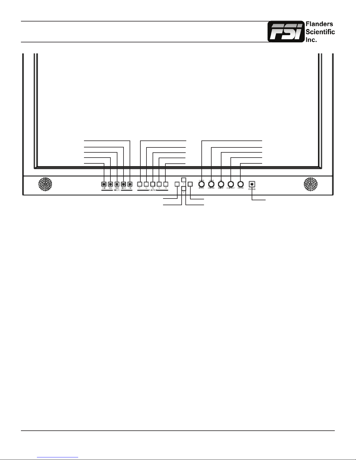
Parts & Their Functions
DVI
VIDEO
YPbPr
SDI 2
SDI 1
MENU
DOWN
F1
F2
F3
F4
F5
ENTER
UP
PHASE / H POS
CHROMA / V POS
BRIGHT / Ref POS
CONTRAST / F Stop
VOLUME / Reset
POWER
• SDI 1: Used to select SDI Input 1 as the active Input.
• SDI 2: Used to select SDI Input 2 as the active Input.
• YPbPr: Used to select the Component Analog Input as the active Input.
• VIDEO: Used to select the Composite Analog Input as the active Input.
• DVI: Used to select the DVI-I Input as the active Input. DVI-Digital / DVI-Analog toggle is available in the System Menu
(Menu/System/DVI Selection).
• F1: Assignable function key. This key’s function is selectable from the Function Menu.
• F2: Assignable function key. This key’s function is selectable from the Function Menu.
• F3: Assignable function key. This key’s function is selectable from the Function Menu.
• F4: Assignable function key. This key’s function is selectable from the Function Menu.
• F5: Assignable function key. This key’s function is selectable from the Function Menu.
• MENU: Used to enable On Screen Menu.
• UP: Used in combination with DOWN and ENTER Keys to navigate On Screen Menu.
• DOWN: Used in combination with UP and ENTER Keys to navigate On Screen Menu.
• ENTER: Used in combination with UP and DOWN Keys to navigate On Screen Menu. The ENTER button is used to
conrm selections within the On Screen Menu.
• POWER: Used to turn power on/off.
• VOLUME: Used to adjust volume. Press down on this knob to instantly mute or unmute the volume.
• CONTRAST: Used to adjust contrast higher or lower. Pressing down on the center of this button will return the contrast
setting to its default position.
• BRIGHT / F.D. / Ref POS: Used to adjust brightness higher or lower. Pressing down on the center of this button will
return the brightness setting to its default position. The brightness knob should NOT be used increase the overall peak
white luminance of the unit, use the Luminance setting on the System Menu to adjust overall luminance.
• CHROMA / V POS: Used to adjust chroma higher or lower. Pressing down on the center of this button will return the
chroma setting to its default position.
• PHASE / H POS: Used to adjust phase. Pressing down on the center of this button will return the setting to default. Hue
is locked by default on SDI, but can be unlocked by the SDI Hue Adjustment option on the System Menu.
• Tally: Three color tally lamp controlled via remote control.
Return to Table of Contents
5
© 2014 Flanders Scientic, Inc.
Page 6
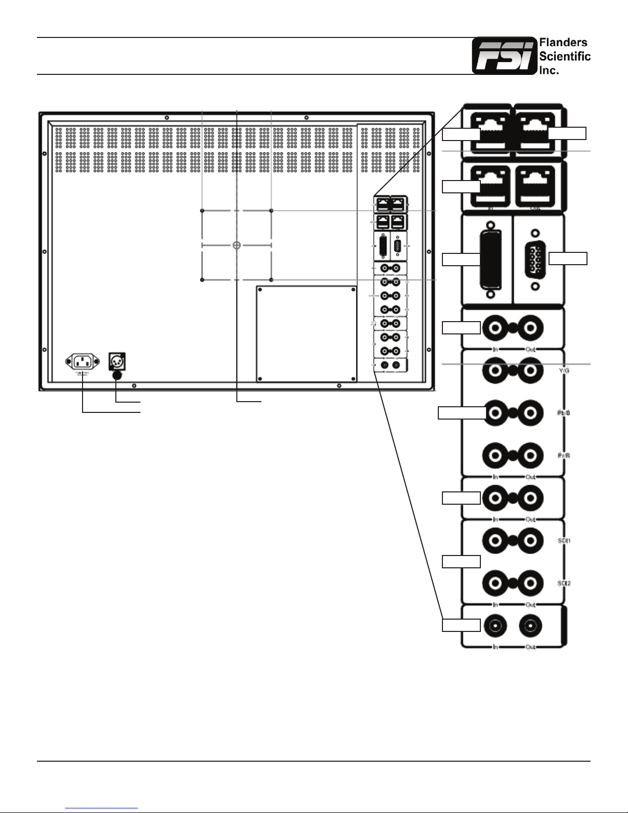
Parts & Their Functions
DC Power
AC Power
100mm VESA
LAN
RJ-485
DVI-I
Video
Component
GPI
RS-232
• LAN: IP Control via select programs. This feature is in beta.
• GPI: General Purpose Interface for Contact Closure Remote Control.
Remote Control Functions can be assigned from the GPI Menu.
• RS-485: RS-485 Ports (In/Out) for looping remote control interface.
• DVI-I: DVI-I Input. Supports both DVI-Analog & DVI-Digital.
Analog / Digital Toggle is found on System Menu.
• Video In/Out: Composite Video Input & Loop Through.
• Component In/Out: Component Video (SD & HD autosensing) Input & Loop
Through.
Supports both YPbPr & RGB signals.
• Ext. Sync. In/Out: External Reference Synchronization Interface.
• SDI In 1 & SDI In 2: Two Autosensing, Autoswitching, Multi-Format 3G/Dual-Link/
HD/SD-SDI Inputs.
• SDI Out 1 & Out 2: Two looped 3G/Dual-Link/HD/SD-SDI Outputs.
• Audio In/Out: Analog Stereo Mini-phono Audio Input & Output. Unbalanced, Audio
Out delayed by exact amount of monitor video procesisng time to maintain sync.
Ext Sync
SDI
Audio
Return to Table of Contents
6
© 2014 Flanders Scientic, Inc.
Page 7

Menu Navigation / System Status
Main Menu
Pressing the MENU button on the monitor’s keypad will call up the On Screen Menu, as shown below:
Main Menu Function
Function F1 Scopes & Audio Meters 1
Scopes & Audio Meters F2 Scopes & Audio Meters 2
Video F3 Scopes & Audio Meters 3
Audio F4 Marker 1
Marker F5 Measurement (10Bit)
System Function Display On
Alarm
OSD
GPI
Color Management
System Status
Support
Navigating the Main Menu
To navigate the Main Menu simply use the UP and DOWN keys to highlight a category and press the ENTER button to
select the highlighted sub menu. Navigate the sub menu in the same way by using the UP and DOWN keys to highlight a
particular function and press ENTER to toggle between that function’s settings. To exit the menu or back out of a sub menu
simply press the MENU button.
System Status Category
The System Status category does not contain any congurable settings, but does provide important information regarding
your monitor’s serial number, rmware version, & current conguration.
Main Menu System Status
Function Input DVI-D
Scopes & Audio Meters Input Mode 1080p 60hz
Video Overscan Off
Audio Pixel Mapping Off
Marker Volume 16
System Contrast 0
Alarm Brightness 0
OSD Chroma 0
GPI Hue 0
Color Management Model BM210
System Status Version 1.0.00-1969
Support S/N M210A0000
Note that pressing an input button will temporarily call up a secondary system status summary window that will indicate
incoming signal resolution and frame rate, active color space selected on Color Management menu, gamma response
selected on Video Menu, & color matching function selected on Color Management Menu*.
*Color Matching Function toggle only works on OLED units, all other units currently use CIE 1931 CMF only.
Return to Table of Contents
7
© 2014 Flanders Scientic, Inc.
Page 8
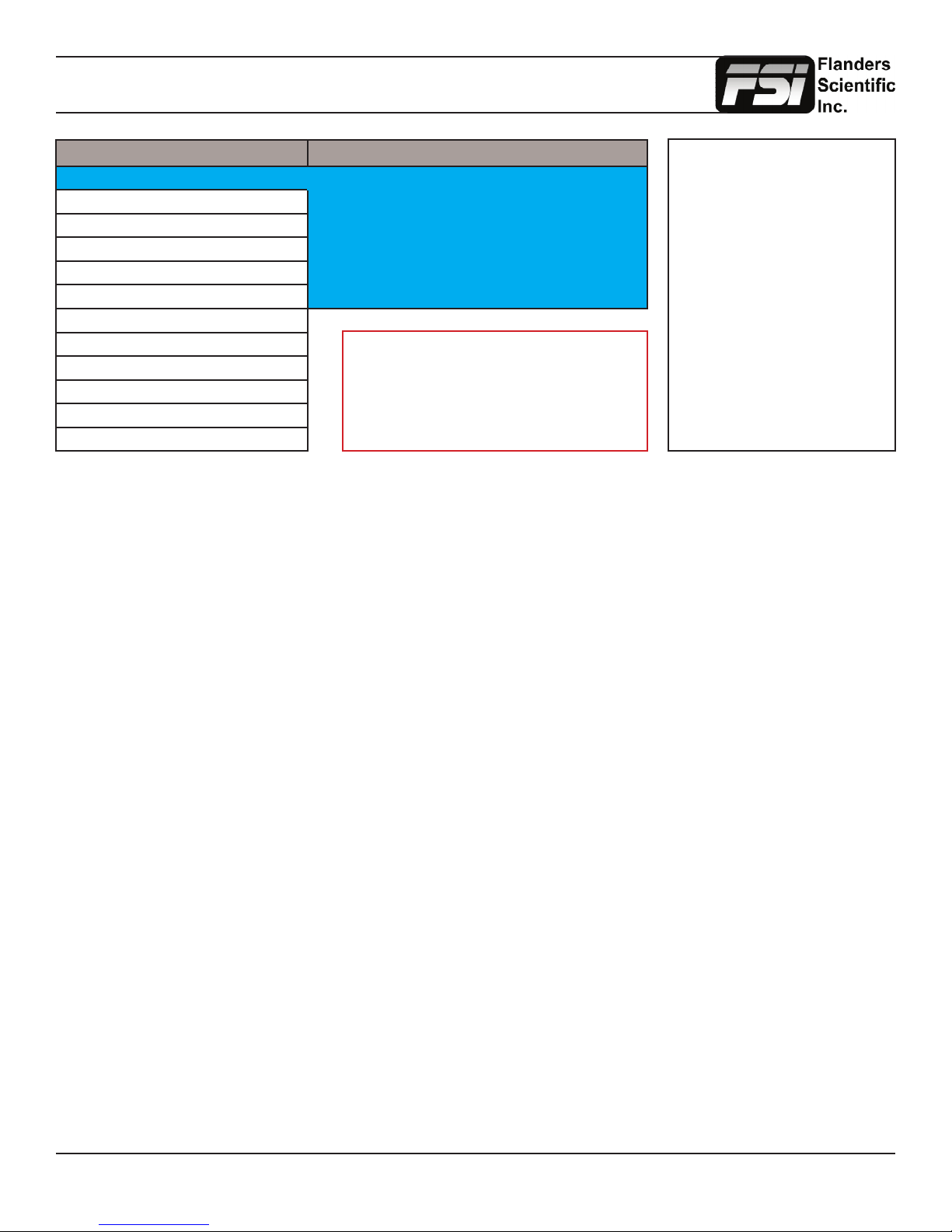
Function Menu
Main Menu Function
Function F1 Scopes & Audio Meters 1
Scopes & Audio Meters F2 Scopes & Audio Meters 2
Video F3 Scopes & Audio Meters 3
Audio F4 Marker
Marker F5 Measurement (10Bit)
System Function Display On
Alarm
OSD
GPI
Color Management
System Status
Support
The Function Menu allows you to assign user selectable functions to any of the 5 function buttons (F1, F2, F3, F4, & F5)
on the monitor keypad. Many monitor features listed as assignable options in the function menu are also selectable via the
embedded menus and are present simply to provide an option for faster, single button press access to the desired function.
Other features listed require a function key for activation, but may have associated customizable settings that can be found
in other menus.
Assigning Function Keys
To assign a function to a function key highlight one of the 5 Function lines and press ENTER. A list of assignable functions
will appear. Select the desired function with the UP and DOWN buttons and press ENTER to assign that function to the
corresponding function key. The Function Display option at the bottom of the Function Menu gives you the option to have
a temporary conrmation window appear on screen after a function key is pressed that will identify the function that was
turned on or off.
WARNING: Changing a function button
assignment does NOT automatically
turn an active function off. Make sure to
disable unwanted active functions before
changing function button assignments.
NOTE: Many features (Waveform,
Vector Scope, Audio Level
Meters, etc.) require a function
key in order to operate. Some
menus (such as the Scopes &
Audio Meters Menu) only set
your display preferences while a
corresponding function key must
be assigned to turn the feature
on and off. If you are having
trouble with a monitor feature
make sure you have assigned
the proper function key and any
corresponding menu settings.
Scopes & Audio Meters 1, 2, 3
These functions toggle on/off a Scopes & Audio Meters prole. Three prole slots are available from the Scopes & Audio
Meters Menu and each prole can be set to a specic function key allowing you to instantly toggle between various types of
Scope and/or Audio Level Meter congurations. Please note that if you have set both Scopes Windows to the Off position in
the Scopes & Audio Meters menu nothing will appear on screen when you toggle this function (see Scopes & Audio Meters
Menu section of this manual for more details).
Cross Hatch
The Cross Hatch function toggles on/off the onscreen display of a graphical cross hatch overlay.
Marker 1, 2, 3
These functions activate the onscreen display of the preset Area, Safety, Custom Graticules, or Active Boundary Markers as
set in the Marker Proles. Marker Proles can be customized via the Marker Menu. By utilizing this function you can toggle
on/off your selected markers with a single function key (see Marker Menu section of this manual for more details).
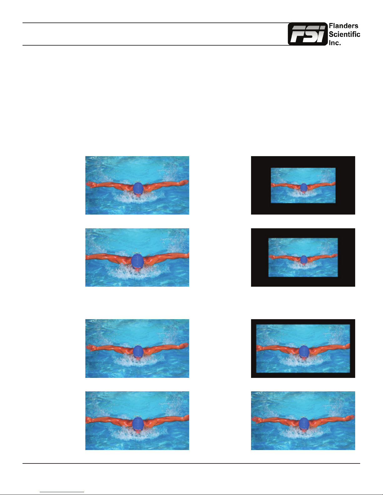
Overscan
The Overscan function can work with 1:1 Pixel mapping mode on or off. With 1:1 Pixel to Pixel mapping mode turned off
the Overscanned image is scaled full screen. With 1:1 Pixel to Pixel mapping mode turned on the image remains unscaled,
but the area lying outside of the active scan area is blacked out. This area represents the same area not visible with Pixel
to Pixel mode off.
Return to Table of Contents
8
© 2014 Flanders Scientic, Inc.
Page 9
Function Menu
Details on Overscan Function
With the overscan function off all active lines of video can be displayed on screen. With overscan on a small percentage
of the outermost active video will not be displayed. Additionally, the monitor can scale the overscanned video full screen
or ‘blackout’ the outlying area while maintaining a pixel to pixel display of the video inside the active scan area. To toggle
between these variations of Overscan use the 1:1 Pixel to Pixel mapping function. With both Pixel to Pixel mapping and
Overscan selected the area outside of the active scan will simply be blacked out, but the active video will not be scaled
outside of the 1:1 pixel scan. With Pixel to Pixel mapping off and overscan on the active scan area will be scaled full screen.
To view all active lines in Pixel to Pixel mapping mode make sure to turn Overscan off.
Overscan Examples
(Images represent 720p source on BM230)
Pixel to Pixel Off
Overscan Off
Pixel to Pixel Off
Overscan On
More Overscan Examples
(Images represent 1080i source on BM230)
Pixel to Pixel Off
Overscan Off
Pixel to Pixel On
Overscan On
Pixel to Pixel On
Overscan Off
Pixel to Pixel On
Overscan On
Pixel to Pixel Off
Overscan On
Return to Table of Contents
Pixel to Pixel On
Overscan Off
9
© 2014 Flanders Scientic, Inc.
Page 10
Function Menu
Sub Window
Largely deprecated for use on CFE2 equipped units. For side by side viewing on CFE2 units please use the dedicated PIP
function instead. The Sub Window function enables a Picture by Picture mode. After assigning the Sub Window function
to a function key the rst key press will result in a picture by picture display of your active input. Once sub window mode is
active you can press down on the H POS rotary knob to freeze the image on the right while the image on the left will continue
to show your live source. Once frozen you can also switch to any other input provided that the resolution of that input is the
same as the frozen source. To exit sub window simply press the assigned function key again.
Pixel Mapping
The Pixel Mapping function toggles between various available pixel mapping options. Options vary depending on the
incoming source, but may include the following:
1:1 Pixel Mapping: 1 pixel of incoming source is displayed as 1 pixel onscreen. If the incoming source resolution is less
than the total pixel count of the monitor your source will not ll the screen. This is often referred to as a postage stamp
representation of the source. If the incoming source resolution is greater than the total pixel count of the monitor then only
a portion of the incoming source will be shown onscreen, but the pixel position function (controlled by the H POS rotary
knob) may be used to view different sections of the 1:1 pixel representation. The monitor’s tally light will ash to remind
you that you are in 1:1 pixel mapping mode if any portion of the image is not shown on screen when in 1:1. This pixel
mapping mode can be combined with the SD Aspect Function (Anamorphic toggle) to activate a PAL SD FHA viewing
mode on the monitor. Once pixel mapping is active pressing down on the H POS knob will move the source to a different
onscreen position when pressed. Please note that if the incoming source is the same resolution as the panel the image
will not move. On monitors with lower than 1920x1080 resolution this feature can be used to view any section of a 1080
source in a native 1:1, unscaled format. Similarly, on all native 1920x1080 or 1920x1200 resolution monitors this mode
will allow you to view any portion of an incoming 2K source in an unscaled 1:1 onscreen representation.
2:1 Pixel Mapping (SD sources only): Every individual pixel of the incoming source is represented by four pixels onscreen.
This scaling algorithm is simple and allows for a largely artifact free double size version of the 1:1 Pixel Mapping Mode for
SD sources. While 2:1 scaling will still not ll the entire screen on a 1920x1080 resolution monitor, it does use a majority
of the vertical screen height and provides an excellent quality large scale representation of the SD source.
Full Screen Mapping: The full screen mode will scale the incoming source to ll as much of the screen as
possible while preserving the incoming source’s native aspect ratio. If the incoming source and panel share
the same resolution then there will be no difference between 1:1 pixel mapping and full screen pixel mapping.
Please note that the Overscan function will be represented differently based on the pixel mapping selection that you select.
Pixel Position
This feature is a part of the Pixel Mapping function and provides a toggle for positioning a 1:1 Pixel to Pixel mapped
representation of an incoming source on different areas of the screen. Once pixel mapping is active the H POS knob
will move the source to a different onscreen position when pressed. Please note that if the incoming source is the same
resolution as the LCD panel the image will not move. The pixel position feature does not work unless the 1:1 Pixel to Pixel
mapping mode function is turned On. On 7”, 9”, and 17” monitors this feature can be used with the Pixel to Pixel Mode
to view any section of a 1080 source in a native 1:1, unscaled format. Similarly, on all native 1920x1080 or 1920x1200
resolution monitors this mode will allow you to view any portion of an incoming 2K source in an unscaled 1:1 onscreen
representation.
H/V Delay Mode
This mode activates the Horizontal and Vertical Delay function to highlight the horizontal and vertical blanking portions of
the incoming signal.
Mono Mode
This mode activates the Monochrome function. Press once to turn on and again to turn off.
Return to Table of Contents
10
© 2014 Flanders Scientic, Inc.
Page 11
Function Menu
SD Aspect Ratio
Toggles between 4:3 and Anamorphic display of Standard Denition source. This function should be set to match the SD
source being viewed. The default setting is 4:3. If used in conjunction with 1:1 pixel mapping this function can also activate
a PAL SD FHA viewing mode.
Full Screen
This function simply stretches any incoming source to ll the entire screen. Unlike the Zoom feature this full screen stretch
does not preserve aspect ratio, but it does keep all of the active video signal present. Though the full screen mode has
many potential uses it was designed primarily for use with rasterizers that generate a 16:10 or 16:9 aspect 1024x768 output.
Enabling Full Screen mode allows the monitor to stretch the image as intended by the rasterizer.
Pixel Zoom
The Pixel Zoom function will generate a positionable and resizable rectangle on screen. The rectangle may be moved left or
right using the H POS rotary knob and up or down using the V POS rotary knob. The Ref POS rotary knob may be used to
change the size of the onscreen rectangle. Using these three rotary knobs you can select any area on screen and then press
down on the F Stop rotary knob to zoom to the selected area. This pixel zoom feature is designed to work with any HD signal
formats. A ashing tally light will be activated on your monitor whenever you are in a zoomed mode as a reminder/warning
that the entire incoming signal is not being shown on the monitor. To exit the zoomed mode simply press down on the F
Stop rotary knob once more. To exit the Pixel Zoom feature entirely simply press the function button assigned to this feature
once more. The Pixel Zoom function allows for an essentially artifact free, high quality zoom on any portion of an HD signal.
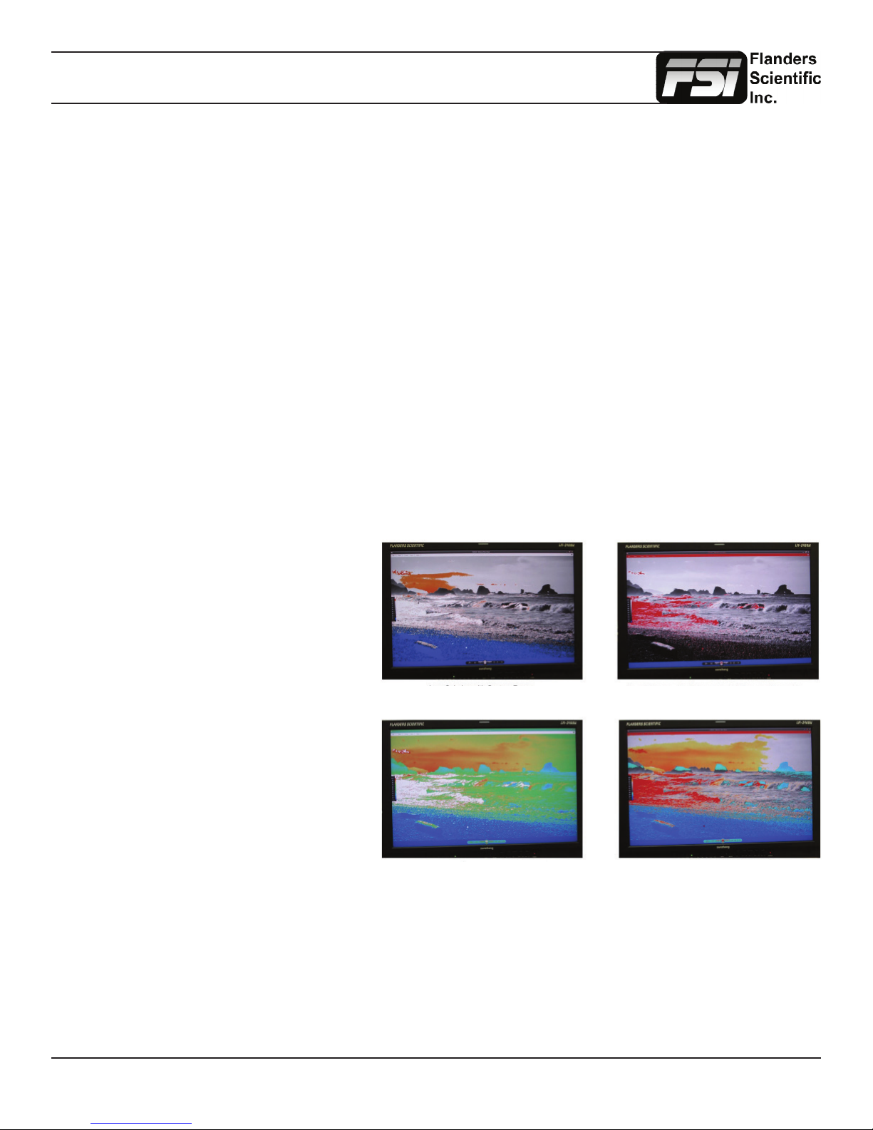
LUM Coloring
This function generates an articial luminance
map of the incoming source that can be
particularly useful in identifying overexposed
areas in any given shot. An onscreen scale
helps indicate what articial color corresponds
to what luminance level. The scale will follow
the selected Waveform Scale set in the Scopes
& VU Meters Prole 1: you can choose from
IRE, Digital Levels, or Voltage. In its default
conguration the LUM Coloring feature will
highlight all levels above 100IRE as white and
all levels below 0 IRE as black. In default mode
levels between 0 and 100 IRE will be color
coded. However, you can change the range of
these color coded regions to any preferred
setting by using the monitor’s rotary knobs.
The H POS rotary knob will adjust the lower
limit of the lower color coded region. The
V POS rotary knob will adjust the upper limit
of the lower color coded region. The Ref
POS rotary knob will adjust the lower
LUM Coloring with Custom Range LUM Coloring with All Legal Levels Shown in Greyscale
LUM Coloring in Default Mode
Overexposed Areas in White
Underexposed Areas in Black
Underexposed Areas in Blue
Overexposed Areas in Red
LUM Coloring with Custom Range
limit of the upper color coded region.
The F Stop Rotary knob will adjust the upper limit of the upper color coded region. These color coded ranges are retained in
memory so you can exit and reenter LUM Coloring Mode without having to reset your desired threshold levels.
Blue/Red/Green Only
This function activates the monitor’s Blue Only, Red Only, and Green Only modes. The respective channels can be shown
as just that color (Red, Green, Blue) or as monochrome.
Return to Table of Contents
11
© 2014 Flanders Scientic, Inc.
Page 12
Function Menu
Measurement (10bit & 8bit)
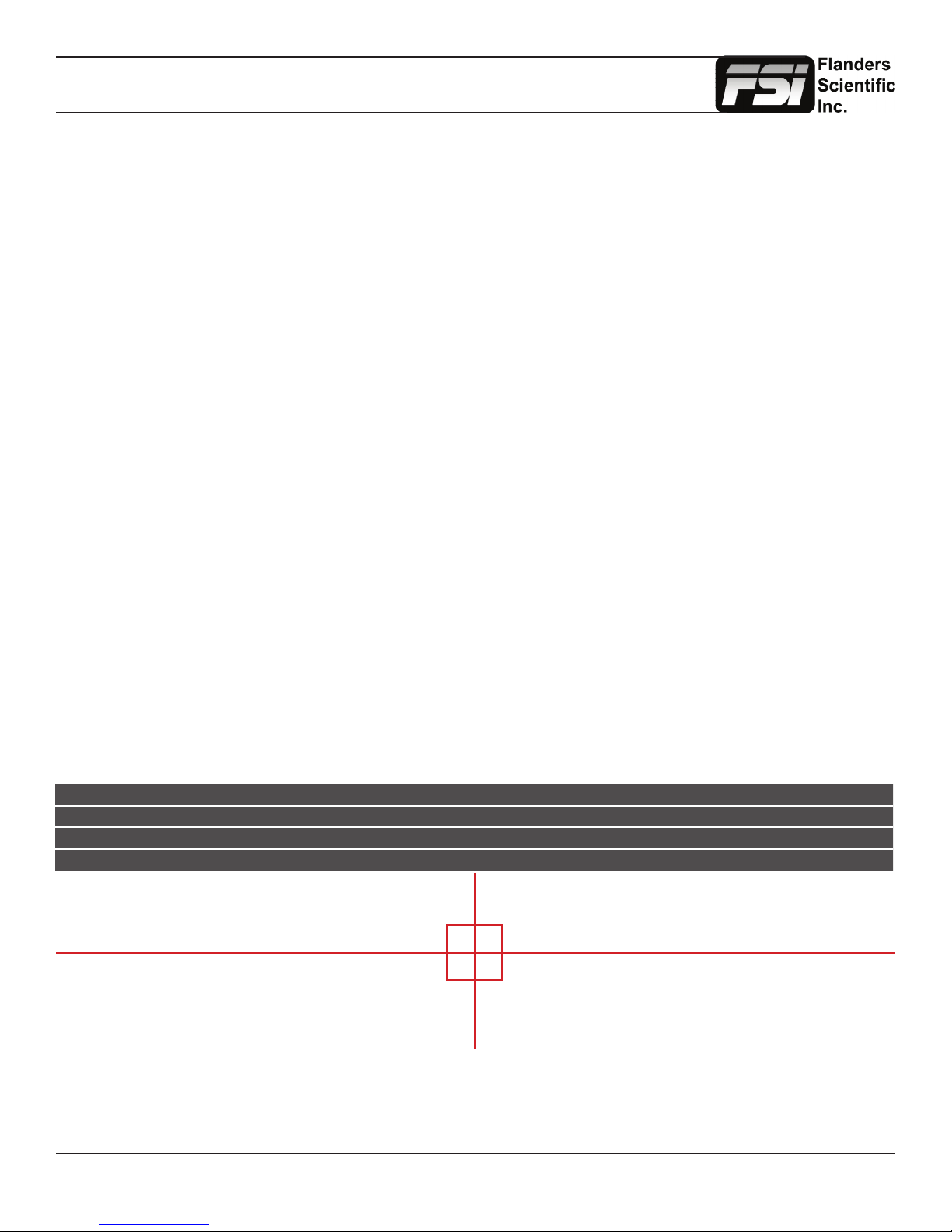
This function allows you to get precise real time YRGB measurements of any point or area within your incoming signal.
With the Measurement function on you can use the H POS and V POS rotary knobs to position your crosshair over the point
within your source that you would like to measure. To reset the vertical or horizontal position of your crosshair back to center
simply press down on the corresponding rotary knob. You may also use the Ref POS rotary knob to select the size of the
sampling area for the measurement data (from a single pixel to a much larger area where the values will be an average of
all pixels within your dened sample area). As you move the crosshair your Measurement data will update in real time. The
Measurement function is available in a 10 bit mode or 8 bit mode and will provide you with the following data in real time:
• Line and Sample (Identies position of your crosshair)
• Y (Luminance as an absolute value between 0-255 for 8 bit and 0-1023 for 10 bit)
• Y% (Luminance level expressed as percentage)
• R% (Red level expressed as percentage)
• G% (Green level expressed as percentage)
• B% (Blue level expressed as percentage)
• R (Red level as an absolute value between 0-255 for 8 bit and 0-1023 for 10 bit)
• G (Green level as an absolute value between 0-255 for 8 bit and 0-1023 for 10 bit)
• B (Blue level as an absolute value between 0-255 for 8 bit and 0-1023 for 10 bit)
You can also press the Ref POS rotary knob to set a reference position onscreen. Once your reference position is set
it will be indicated on screen by a separate crosshair and you will be able to move the active crosshair to obtain a real
time readout of your current and reference positions as well as a separate readout of the precise difference between
current and reference locations. Please note that your reference position is both a spatial and temporal reference meaning
that the values indicated on screen for the reference are for that point on screen at the moment you set the reference.
Pressing the F Stop rotary knob button allows you to set your current crosshair position as an F-Stop Reference
and view differences between this current position and your reference position as an F-Stop value. The F-Stop
reference feature is independent of the Ref POS feature. The F-Stop reference value will always be based on
the levels of your current active crosshair position at the precise moment when the F-Stop knob is pressed.
The crosshair color will follow the color selected for markers from the Marker Menu. To change the color of the Measurement
function’s crosshair change the Marker color.
Measure Line Sample Y1024 R1024 G1024 B1024 Y% R% G% B% F/stop
Current 293 944 249 246 251 217 21.1 20.8 21.3 17.5 -0.0
Ref_Pos 316 994 240 240 241 219 20.1 20.1 20.2 17.7 -0.1
Diff -24 -51 9 6 10 -2 1.0 0.7 1.1 -0.2 0.1
Return to Table of Contents
12
© 2014 Flanders Scientic, Inc.
Page 13
Function Menu
CIE Measurement
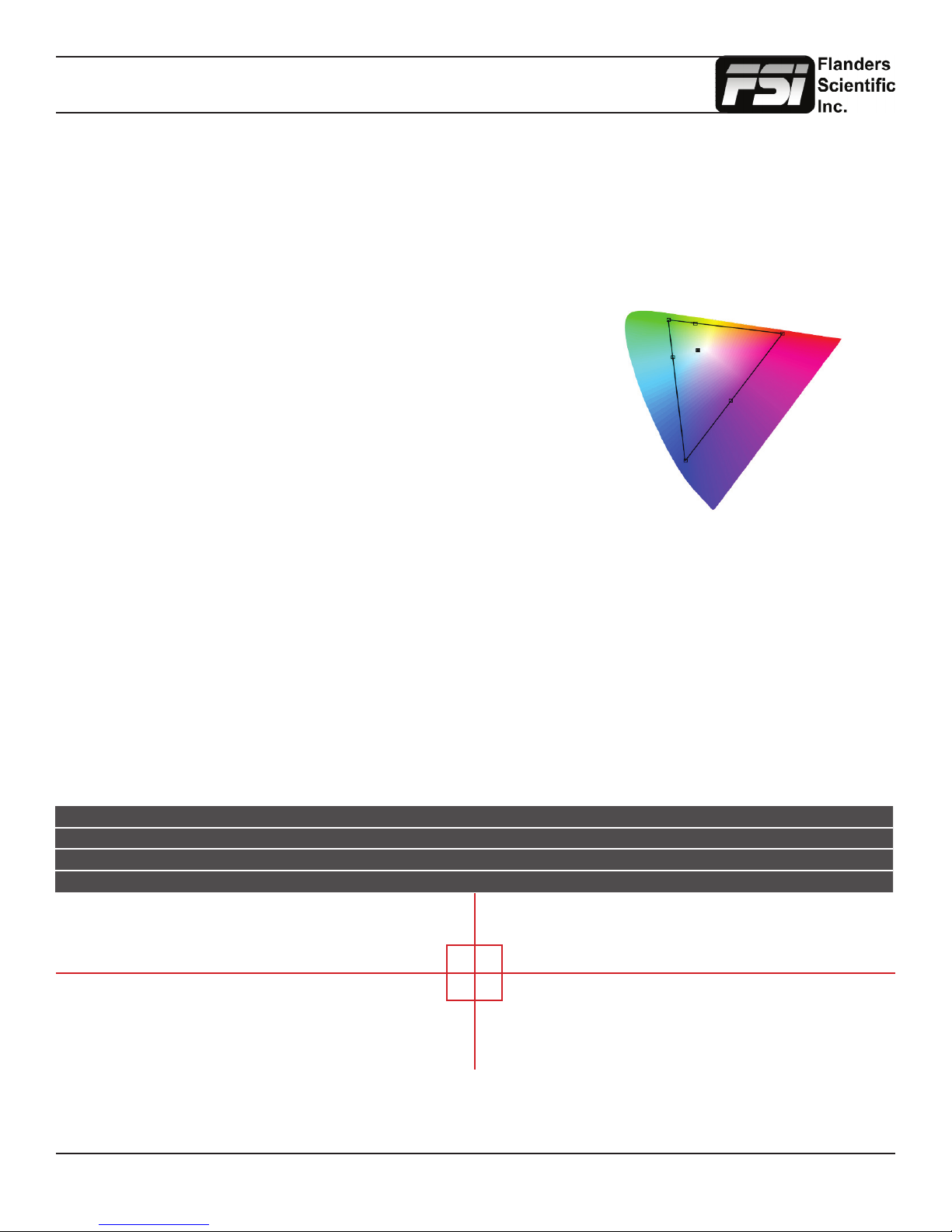
This function allows you to get precise real time chromaticty measurements of any point or area within your incoming
signal as well as a real time plot of the mesured position on a CIE color space diagram. With the Measurement
function on you can use the H POS and V POS rotary knobs to position your crosshair over the point within your
source that you would like to measure. To reset the vertical or horizontal position of your crosshair back to center
simply press down on the corresponding rotary knob. You may also use the Ref POS rotary knob to select the
size of the sampling area for the measurement data (from a single pixel to a much larger area where the values will
be an average of all pixels within your dened sample area). As you move the crosshair your Measurement data
and plot will update in real time. The CIE Measurement function will provide you with the following data in real time:
• Line and Sample (Identies position of your crosshair)
• R’ (Red signal level percentage normalized to 10 bit data range)
• G’ (Green signal level percentage normalized to 10 bit data range)
• B’ (Blue signal level percentage normalized to 10 bit data range)
• Y% (Luminance level as percentage)
• x (CIE 1931 x chromaticty coordinate)
• y (CIE 1931 y chromaticty coordinate)
• u’ (CIE 1976 u’ chromaticty coordinate)
• v’ (CIE1976 v’ chromaticty coordinate)
• dE2000 (difference between current & reference expressed as dE2000 value)
You can press the Ref POS rotary knob to dene a reference position on screen. Once your reference position is set
it will be indicated on screen by a separate crosshair and you will be able to move the active crosshair to obtain a real
time readout of your current and reference positions as well as a separate readout of the precise difference between
current and reference locations. Please note that your reference position is both a spatial and temporal reference meaning
that the values indicated on screen for the reference are for that point on screen at the moment you set the reference.
Pressing the F Stop rotary knob button allows you to toggle the CIE color space diagram between CIE 1931 and CIE 1976
views. Your chromaticty plots are calculated using signal input data relative to your active Color Space selection on the Color
Management menu. Since your reference color gamut for chromaticty calculation follows this selection it allows you to have
Rec709, DCIP3, EBU, or SMPTE C as your reference color gamut. Please note that if you have the Color Space selection set
to Wide Gamut or a custom USER position the reference gamut used for the CIE Measurement feature will default to Rec709.
The crosshair color will follow the color selected for markers from the Marker Menu. To change the color of the Measurement
function’s crosshair change the Marker color.
CIE Line Sample R’ G’ B’ Y% x y u’ v’ dE2000
Current 542 960 971 0 1 18.93 0.6400 0.3300 0.4507 0.5229
Ref_Pos 541 961 1023 1023 1023 100 0.3127 0.3290 0.1978 0.4683
Diff 1 -1 -52 -1023 -1022 -81.7 0.3273 0.0010 0.2529 0.0546 47.678
Return to Table of Contents
13
© 2014 Flanders Scientic, Inc.
Page 14
Function Menu
Focus Assist
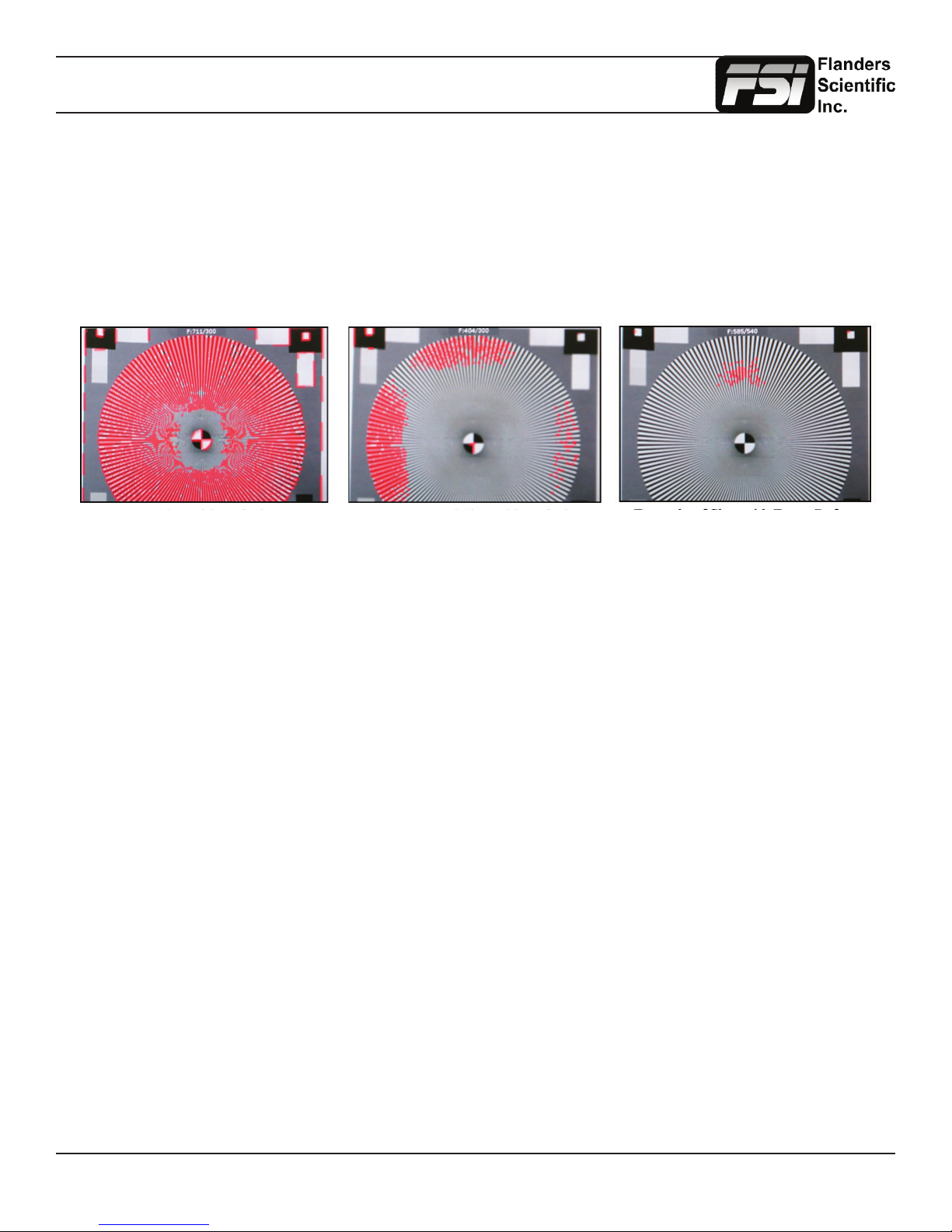
The focus assist feature is comprised of two main parts: a numerical focus meter and a graphical focus highlight.
The numerical focus meter is shown on screen as your current focus value over your reference focus value (i.e.
560/300). When the focus assist feature is activated the rotary knob labeled Ref POS allows you to adjust the
reference focus value. The reference focus value represents the in-focus threshold for the focus highlight portion
of the focus assist feature. Adjusting the focus reference value higher means that the threshold at which the focus
highlight begins to trace in-focus items with a red boundary will be higher. In other words a greater degree of focus
will need to be achieved before the focus highlight feature is visible on screen as a red trace around in-focus objects.
In Focus Shot with Default Focus
Reference Value
Less Focused Shot with Default
Focus Reference Value
Example of Shot with Focus
Reference Value Turned Up
Level B Variable Wipe
When monitoring a Level B 3Gbps SDI signal (monitor must have 3Gbps SDI Input) comprised of two multiplexed 1.5Gbps
HD-SDI signals the monitor will allow you to view these signals in a vertical or horizontal split screen mode. By activating the
Level B Variable Split function while in split screen mode the positioning of the split can be adjusted using the H POS rotary
knob. To quickly reset the split screen positioning to the default center position simply press down on the H POS rotary knob
while the Level B Variable Wipe function is active. Once your desired split screen wipe position is set you can the Level B
Variable Wipe function off to remove the guide line between the two signals.
Still Frame
This function allows you to freeze a video source at anytime. To unfreeze simply press the function key assigned to Still
Frame a second time.
Zoom
This function zooms in on the incoming source until the entire screen is lled. This is strictly a zooming function and does
not alter the native aspect ratio of the source to ll the screen. When viewing a 4:3 source in Zoom mode on a 16:9 display
the aspect ratio of the visible video will remain 4:3 though the entire 16:9 screen will be lled. Essentially the Zoom mode
results in viewing a 16:9 section of the 4:3 source and is most useful when viewing a letterboxed SD source on a widescreen
display so that the letterboxing is not shown and only the video within the letterboxing is present.
DSLR Zoom
This function is designed to be used with many popular DSLR cameras that have preview/record monitoring output in 1080
& 480 resolutions. When DSLR Zoom is active the 16:9 area that will be recorded is scaled to ll the screen. On DSLR
cameras that switch from 1080 to 480 while recording the DSLR Zoom can be left on and the same correct aspect zoom will
be maintained regardless of whether the DSLR is in preview or recording mode. While DSLR Zoom is active the markers
may also be turned on and will be correct relative to the 16:9 video that will be captured to the camera’s memory card. Please
note it may be necessary to toggle the viewing mode preference (Info button on many DSLRs) to ll the screen correctly.
Return to Table of Contents
14
© 2014 Flanders Scientic, Inc.
Page 15
Function Menu
DSLR Zoom (continued)
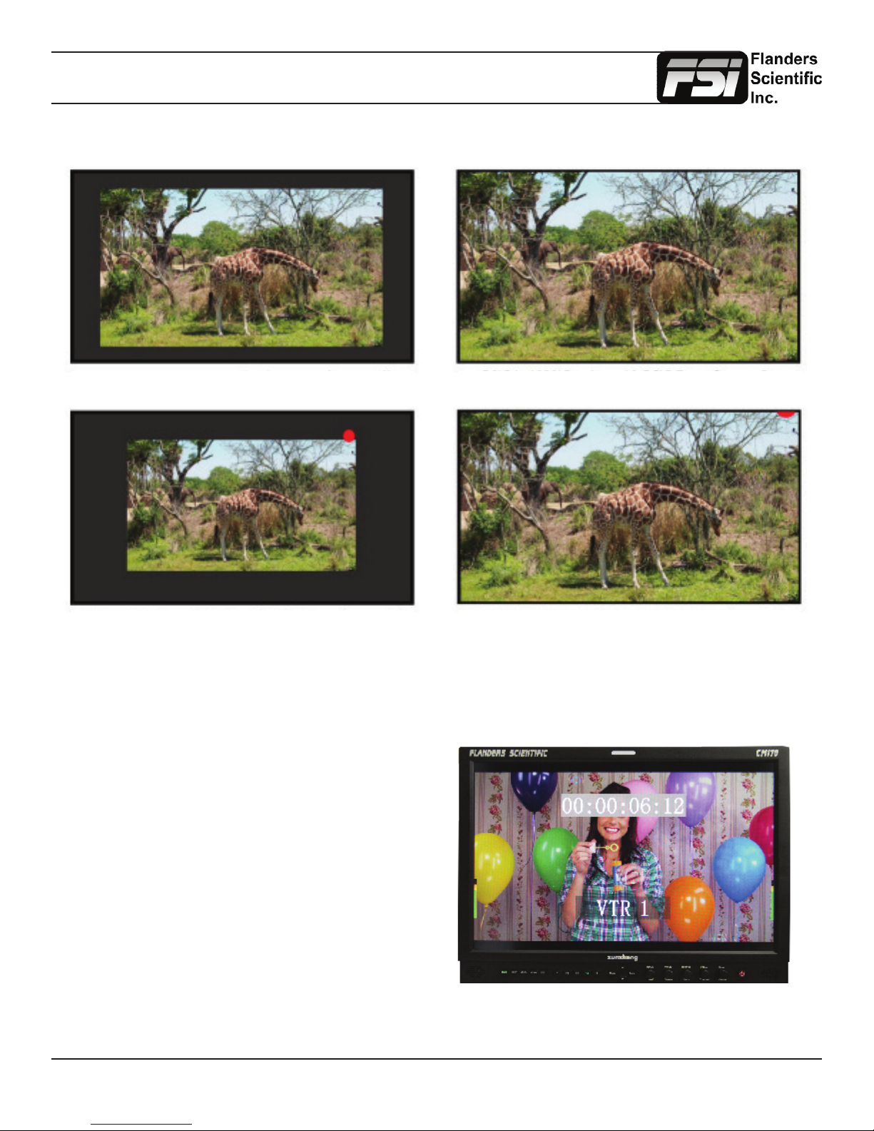
DSLR in 1080i Preview with DSLR Zoom feature Off DSLR in 1080i Preview with DSLR Zoom Feature On
DSLR in 480p Record Mode with DSLR Zoom feature off DSLR in 480p Record Mode with DSLR Zoom feature On
Safety Broadcast
Safety Broadcast is a special monitoring mode designed for Control Room and QC station environments. With Safety
Broadcast mode activated you can have simultaneous display of two audio level meters, Enhanced Source ID display (large
overlay, remotely or manually set), Enhanced Alarm Window Display (large window, red background), and
enhanced timecode display (large timecode overlay
window). Please note that as with the standard Alarm
Monitoring feature the monitor may respond slowly
to user toggles/inputs if a constant alarm condition is
occurring. Toggles for UMD Display, Color, and
Position are found in the Alarm Menu. Vertical or
Horizontal Safety Broadcast Audio Meter selection
is also found in the Alarm Menu.
Return to Table of Contents
15
© 2014 Flanders Scientic, Inc.
Page 16
Function Menu
AFD (Active Format Description)
Activating this function will enable an Active Format Description
reader on the monitor that will provide both a text readout of AFD
data and display corresponding markers onscreen indicating
the portions of the image described by the AFD code. If no AFD
data is present while this feature is active the monitor will show
AFD: NONE in its AFD readout window.
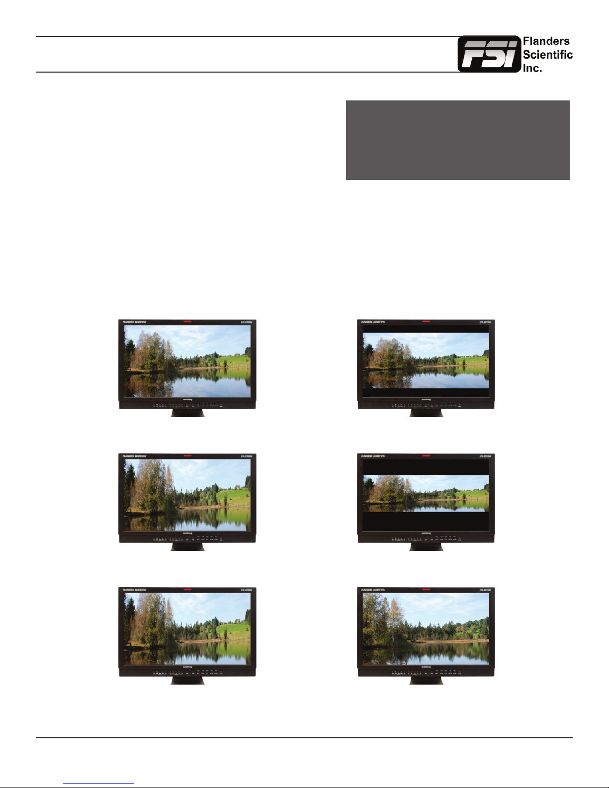
Anamorphic De-Squeeze
This feature gives you the ability to de-squeeze HD signals coming from cameras utilizing anamorphic lenses that may not
have a built in de-squeeze feature of their own. This can be particularly useful in applications outside of post production,
especially onset monitoring, where de-squeezing such signals in real-time may otherwise not be possible. The de-squeeze
modes available are 1.3, 2.0, and 2.0mag. This feature is in addition to, and not a substitute for, the SD Aspect Ratio function.
To use this feature set Anamorphic DeSqueeze to a function button, which will allow you to toggle the de-squeeze on and
off. To set the desqueeze ratio/magnication go to the Video Menu and select your desired Anamorphic De-Squeeze mode.
Anamorphic De-Squeeze Modes
image position horizontal center
with alternative 14:9 center
AFD: 0x0d
code frame 16:9
active image 4:3
1.3x Anamorphic Original 1.3x Anamorphic De-Squeeze
2.0x Anamorphic Original 2.0x Anamorphic De-Squeeze
2.0x Anamorphic Original
2.0x mag Anamorphic De-Squeeze
Return to Table of Contents
16
© 2014 Flanders Scientic, Inc.
Page 17
Function Menu
Invert Screen (LM-0950W Only)
Allows the image to be ipped onscreen in real-time. This function only works on the LM-0950W.
CX Scale
This scaling mode was designed specically to allow the scaled down and top centered ’gate check’ output from Codex™
ARRIRAW Recorders to be scaled full screen. Once assigned to a function key you can quickly enter or exit this custom
scaling mode with a single button press. Please note that some functions, such as markers, will not work while this mode is
active. However, other useful functions such as Waveform and Vector Scope will continue to operate normally.
C-Log, S-Log, S-Log2, S-Log 3 and BMD-Log Modes (Also selectable via Video Menu)
These modes allow for easier on-set monitoring of uncorrected of C-Log, S-Log, S-Log2, or BMD Cinema Camera Film
Mode Output by roughly normalizing the footage. For all Log modes there is both a Standard and Full selection. The
Standard selection is suitable for most applications, but does clip highlights to allow for a brighter overall image. The Full
mode is best used for scenes with extremely wide latitude or scenes that are just very bright overall. Full mode preserves
the entire native latitude of the signal (nothing is clipped), but this can result in a rather dark image in many applications.
We provide both for this reason and you can quickly toggle between them as needed for different applications by assigning
these modes to function keys. These modes should only be used to offer on set viewers a rough normilization of the footage
to give them an idea of what the content might look like as a starting point in post production. In other words, it provides you
with a helpful tool to show on set viewers something that does not look ‘at’. These modes are not a replacement for full 3D
LUT transforms and not a substitution for proper color correction in post production applications. For more advanced Log
mode normalization use a custom 3D DIT LUT.
Rec. Status Tally
This function is designed for use with cameras that output Start/Stop Record ags in the ancillary data of their serial digital
output. To activate this function set Rec. Status Tally to a function button and press that function button once. While active
the monitor’s red tally light will turn on when the Start Record SDI ag is detected and will turn the red tally light off when the
Stop Record SDI ag is detected.
On-Screen Tally
When activated this function will generate an onscreen box that mirrors the status of the physical tally on the monitor’s bezel.
This can be particularly useful in applications where the physical tally may be obscured.
Picture In Picture (PIP) - Live Side by Side and Picture In Picture Viewing
On BM and CM series monitors (excluding CM-170W), the Picture In Picture function will allow you to toggle Picture In
Picture. Corresponding controls can be found in the System Menu to change your PIP Secondary Input and PIP Mode,
allowing you to select Picture In Picture, Picture And Picture (Side-By-Side Monitoring), or Picture On Picture.
Max Sharpness
In addition to the Sharnpess Level Setting found on the Video Menu there is an assignable function called Max Sharpness
that will allow you to use a function button to toggle in/out of maxium sharpness mode quickly.
Dual Link
CM & BM sereies units equipped with FSI’s second generation Color Fidelity Engine (CFE2) can support Dual Link SDI
(2 x 1.5Gpbs SDI) in addition to single link 3Gbps SDI for advanced signal format support. 3Gbps SDI is the preferred
connectivity method if available, but if single link 3Gbps SDI output from your source is not available you can use the Dual
Link funciton to activate Dual Link SDI support. To activate this capability rst select SDI 1 as your input. Then set Dual Link
to a function button. Then press that designated function button to to turn on Dual Link mode. Once active you may need to
set your SDI format manually if no payload ID is present in the signal. To do this go to the SDI format section of the Video
Menu and select the appropriate format.
4K Display (CFE2 Units Only)
This feature is currently in limited beta testing only. Further support & documentation may be offered in conjunction with
future rmware releases.
Return to Table of Contents
17
© 2014 Flanders Scientic, Inc.
Page 18
Marker Menu
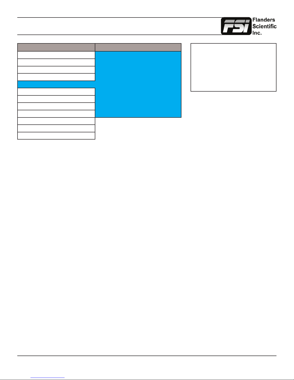
Main Menu Marker
Function Marker Select Prole 1
Scopes & Audio Meters Area Marker 4:3
Video Safety Marker 90%
Audio Marker BG. Normal
Marker Center Marker On
System Marker Color White
Alarm Safety in Area On
OSD Active Boundary Off
GPI Graticules Off
Color Management
System Status
Support
Marker Select
Toggles between three Marker Proles. Each prole stores all marker preferences and can be recalled from the function
menu by assigning a function button to a specic marker prole.
Area Marker
Use the Area Marker function to select what type of marker is displayed when the marker function is active. The marker
selections available from this option include most commonly used markers and more complex user designed custom
markers. Area Markers and Safety Markers may be displayed simultaneously provided that the Marker Background function
(described below) is set to Normal.
NOTE: The Marker Menu only sets
your marker preferences. To toggle the
onscreen display of your congured
marker assign the Marker function to one
of the function keys. See the Function
Menu section of this manual for more
details.
Safety Marker
Use the Safety Marker function to toggle the size, in percentage, of the safety marker displayed. This option can be used by
itself or in conjunction with the Area Marker function provided that the Marker Background function (described below) is set
to Normal. The Safety Marker may be displayed relative to the incoming source or the Area Marker by toggling the Safety
in Area option on the Marker Menu.
Marker BG.
The Marker Background setting can be used to toggle how the area that lies outside of the Area Marker or Safety Marker
boundaries is represented. You can select from Normal, Transparent, or Solid.
Center Marker
Toggles whether the center marker (crosshair) is displayed when the marker is activated.
Marker Color
This setting allows you to select the color of the marker being used. This can be especially useful when one color dominates
the screen and an easily visible high contrast marker is desired.
Active Boundary
When turned on, the Active Boundary marker will highlight the edges of any active video area not directly bordering the
monitor’s bezel. This is useful for detecting missing lines in the active video area.
Safety in Area
Toggles whether Safety Marker is shown relative to incoming source or relative to Area Marker (i.e. 4:3)
Graticules & Graticules Info
Toggles Custom Marker Feature On/Off. Use rotary knobs to adjust line positioning. Set Graticules Info to Off to clear line
position and span size readouts.
Return to Table of Contents
18
© 2014 Flanders Scientic, Inc.
Page 19
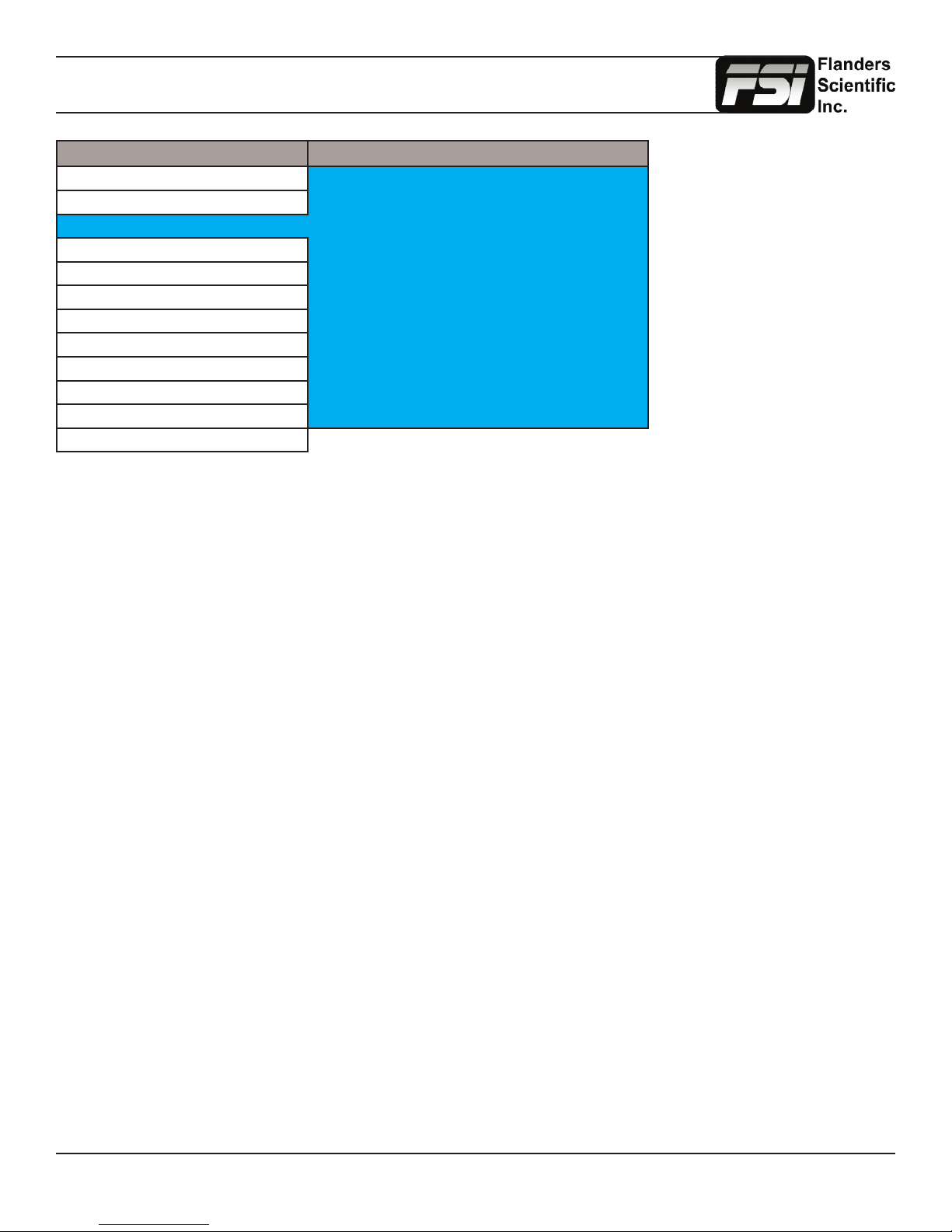
Video Menu
Main Menu Video
Function Gamma Select Gamma 2.4
Scopes & Audio Meters Log Mode Off
Video Color Temperature 6500K
Audio Sharpness Level Default
Marker SD Enhancement Off
System Anamorphic De-Squeeze 4:3
Alarm Signal Mode Auto
OSD Processing Normal Mode
GPI Composite Setup 7.5 IRE
Color Management Component Setup YPbPr SMPTE/N10
System Status SDI Format Auto
Support
Gamma Select
This setting allows you to specify the desired gamma response of the monitor in 0.2 step increments ranging from a gamma
response of 1.8 to 2.8 as well as 2.35 and 1.0. The default gamma setting is 2.4, but any selection may be chosen for instant
adjustment of the monitor’s gamma response. The monitor will override this manual selection in DCI-P3 mode (unless SDI
Format is set to XYZ) & operate with a 2.6 gamma response. Attempting to change the value while in DCI-P3 mode will
result in the monitor exiting this color space mode.
Log Mode (Also selectable via Function Buttons)
This mode allows for easier on-set monitoring of uncorrected of C-Log, S-Log, or BMD Cinema Camera Film Mode Output
by roughly normalizing the footage. For all Log modes there is both a Standard and Full selection. The Standard selection
is suitable for most applications, but does clip highlights to allow for a brighter overall image. The Full mode is best used for
scenes with extremely wide latitude or scenes that are just very bright overall. Full mode preserves the entire native latitude
of the signal (nothing is clipped), but this can result in a rather dark image in many applications. We provide both for this
reason and you can quickly toggle between them as needed for different applications by assigning these modes to function
keys. These modes should only be used to offer on set viewers a rough normilization of the footage to give them an idea of
what the content might look like as a starting point in post production. In other words, it provides you with a helpful tool to
show on set viewers something that does not look ‘at’. These modes are not a replacement for full 3D LUT transforms and
not a substitution for proper color correction in post production applications.
Color Temperature
Use this setting to set the desired color temperature. You can instantly toggle between 3200K, 5000K, 5600K, 6500K,
and 9300K. 6500K is the default setting. Please note that in DCI-P3 mode the monitor will override this manual setting.
Attempting to select a Color Temperature setting manually with DCI-P3 mode active will result in the monitor exiting DCI-P3
color space mode.
SDI Black Level
Use this toggle to set the monitor’s black level for Video (Legal) range or Data (Full) range. Please ensure that your video
signal is setup to match this setting. When set to Video, bit level 16/64 (8 or 10 bit) will be the blackest level on screen. Levels
below 16/64 will not be distinguishable from level 16/64. When set to Data, bit level 0/4 will be the blackest level on screen
and any levels above this will be dinstinguishable as brighter levels. Once set to match your video signal path the brightness
knob can be used to make subtle adjustments to optimize lowlevel response for your particular viewing environment.
Return to Table of Contents
19
© 2014 Flanders Scientic, Inc.
Page 20
Video Menu
Sharpness Level
This function is a peaking level adjustment and produces an effect very similar to a physical aperture adjustment. By
adjusting sharpness lower the image will look softer and by adjusting sharpness higher the image will look sharper. Please
note that perceived sharpness may also be affected by video processing and pixel mapping settings.
SD Enhancement
This toggle applies maximum sharpening and video quality enhancement to SD video sources.
Anamorphic De-Squeeze
Toggles between 1.3, 2.0, and 2.0mag HD Anamorphic De-Squeeze ratios. This is used in conjunction with the Anamorphic
De-Squeeze function described in the Function Menu portion of this manual.
Signal Mode
Selecting ‘Film’ for this setting allows the monitor to compensate for material with 2:3 pulldown to provide a smoother image.
Selecting ‘TV’ for this setting processes the incoming video signal with no 2:3 pulldown compensation. Selecting ‘Auto’ will
automatically trigger ‘Film’ mode anytime 2:3 pulldown is detected.
Processing
The Processing setting has three options: Normal, Fast, & Noise Reduction. In Normal mode the monitor will display
interlaced video as interlaced and have a very low latency processing delay. In Fast mode the video processing delay is
further improved to provide the lowest possible processing latency, but ancillary functions and menu displays are updated
more slowly. In Noise Reduction mode video processing delay is increased to allow for additional noise reduction processing
and the monitor will deinterlace the signal and display it as progressive.
Show PsF as
Select between Interlaced or Progressive to instruct the monitor how to handle and show PsF content on screen. Please
note that when to set Progressive this will add processing delay even if the signal is not PsF. Set to interlaced for lowest
possible processing delay. Please note that some features, like Horizontal Audio Level Meters, are NOT compatible with
‘Show PsF as’ set to Progressive.
Composite Setup
Allows you to toggle between 0 or 7.5 IRE setup selection for composite sources.
Component Setup
Using the Component Setup feature allows you to specify what type of component signal you are sending to the monitor.
Select from YPbPr SMPTE/N10, YPbPr Betacam, YPbPr MII.
SDI Format (ONLY APPLIES TO 3Gbps & Dual-Link SDI ENABLED MONITORS)
FSI Monitors are capable of detecting the payload ID contained in an SDI signal. However, some sources or upstream
equipment may not generate or pass payload ID. For sources lacking proper Payload ID you may override the SDI Format
auto detect function and manually select the appropriate format. It may be necessary to force the monitor to re-sync to a
signal when changing formats at the source even when set to Auto. You can force the monitor to re-sync by either reselecting
Auto from the SDI Format menu, selecting the appropriate format manually from the SDI Format Menu, or simply toggling
to another input and back to the input in use. Please note that on monitors with a selectable color space option that XYZ
signals will be mapped to the color space selected on the Color Management menu.
Flicker Free Mode (Only applies to OLED units)
When turned ON this mode eliminates the low frame rate icker typical of OLED monitors with ultrafast pixel respone times.
For optimal display performance and comfortable viewing we suggest setting Flicker Free Mode to ON for 24p and 25p
material and setting Flicker Free Mode to OFF for higher frame rate material (e.g. 59.94i/p, 50i/p, etc.)
Return to Table of Contents
20
© 2014 Flanders Scientic, Inc.
Page 21
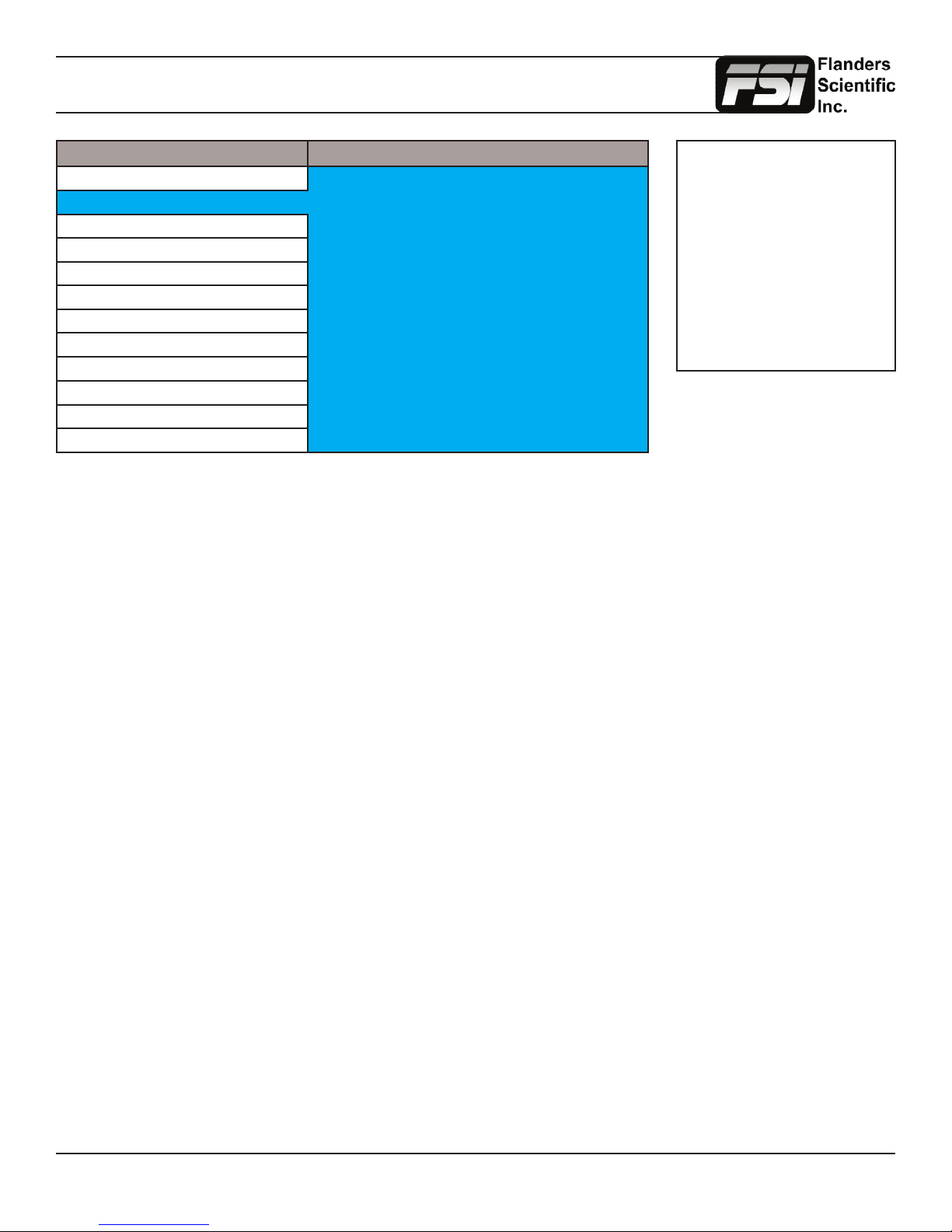
Scopes & Audio Meters Menu
Main Menu Scopes & Audio Meters
Function Scopes & Audio Meters Prole 1
Scopes & Audio Meters Window 1 Luminance
Video Window 2 Vector
Audio Waveform Position Bottom Right
Marker Scopes Stack Horizontal
System Waveform Scale IRE Level
Alarm Audio Display Mode Pairs
OSD Alignment Level -18 dBFS
GPI Permitted Max Level -9 dBFS
Color Management Audio Display Channels 1-16
System Status Ballistics True Peak
Support Peak Hold Time 2
Scopes & Audio Meters Prole 1, 2, 3
The Scopes & Audio Meters menu allows you to setup three Scopes & Audio Meters Proles, each capable of storing all of
the congurable settings found on the Scopes & Audio Meters Menu. To congure a Prole simply select the Prole number,
1 through 3, from the top of the Scopes & Audio Meters menu page. Once you have selected the desired prole number any
settings you change will become associated with that prole number. Changing from one prole to another from the Scopes
and Audio Meters menu will automatically recall your last settings for that prole. Once you have congured your Scopes
& Audio Meters proles you can assign a specic function key to a particular prole, which allows you to instantly switch
between different types of Scope and/or Audio Meters modes without having to go back into the onscreen menu.
NOTE: The Scope & Audio
Meters Menu only sets your
Waveform, Vector, & Audio Level
Meter display preferences. To
toggle the onscreen display
of your congured Scopes &
VU Meters proles assign the
Scopes & VU Meters proles to
specic keys. See the Function
Menusection of this manual for
more details.
Window 1 & Window 2
Two scope windows can be displayed simultaneously so you can view any two of the following modes at the same time:
Luminance (Standard Waveform), Vector Scope, Hue Vector*, RGB Parade, GBR Parade, RGB Overlay, YCbCr, YCbCr
Overlay, Column (YRGB Peak), Histogram, Color Histogram, RGB Histogram, Audio Loudness, Audio Phase, and Vertical
Audio Level Meter. Please note that displaying two Scope Windows at the same time will cause the Scopes to update more
slowly than displaying just one Scope Window. To display just one scope Window select OFF in the secondary window
selection. An additional audio level meter mode called horizontal audio level meter is also selectable. This mode displays
meters horizontally across the top of the screen, but cannot be used in conjunction with any other Scope modes. Waveform
Intensity and Gain can be adjusted by turning the H POS and V POS rotary knobs. Default Scope Intensity as
of rmware version 9.42 is 75% of the maximum level. Hue Vector Intensity, Gain, Reference Vector Angle, and
Percentage of Reference Vector can be adjusted with the H POS, V POS, Ref POS, and F Stop rotary knobs. Audio
Loudness metering can be pasued and reset using the RESET rotary knob.
*Hue Vectors graticule designed by Alexis Van Hurkman and used under Creative Commons Liscense.
Waveform Position
Use the Waveform Position toggle to select in what area of the screen you would like your Scopes to be displayed.
Scopes Stack
Use this option to select whether the Scope Windows are stacked vertically or positioned horizontally next to each other
when utilizing two Scope Windows.
Waveform Scale
This option allows you to choose what type of scale is used on the Waveform Monitor. You may select from V Level (for a
voltage based scale), IRE Level (for an IRE based scale 0-100), or Digital Level (for a 8 bit digital level based scaled, 0-255).
Return to Table of Contents
21
© 2014 Flanders Scientic, Inc.
Page 22
Scopes & VU Meters Menu
Main Menu Scopes & VU Meters
Function Scopes & VU Meters Prole 1
Scopes & Audio Meters Window 1 Luminance
Video Window 2 Vector
Audio Waveform Position Bottom Right
Marker Scopes Stack Horizontal
System Waveform Scale IRE Level
Alarm Audio Display Mode Pairs
OSD Alignment Level -18 dBFS
GPI Permitted Max Level -9 dBFS
Color Management Audio Display Channels 1-16
System Status Peak Hold Time 2
Support OSC Mode Off
Alignment Level
Allows audio level meter alignment level to be set to -12dBFS, -14dBFS, -16dBFS, -18dBFS or -20dBFS, -22dBFS.
Audio Display Mode
This option can be set to either Groups or Pairs. When organized in pairs the odd channels will be displayed on the left side
of the screen and even channels of the right side of the screen. When organized in groups the channels will be arranged
with all channels of an Audio Group displayed on the same side of the screen together.
NOTE: The Scope & VU Meters
Menu only sets your Waveform,
Vector, & Audio Level Meter
display preferences. To toggle
the onscreen display of your
congured Scopes & VU Meters
proles assign the Scopes & VU
Meters proles to specic keys.
See the Function Menusection
of this manual for more details.
Audio Display Channels
Allows you to select the Audio Level Meters Channels that will be shown on the Vertical or Horizontal Audio Level Meters.
Select from Channels 1-2, 1-8, 9-16, or 1-16.
Permitted Max Level
Allows you to specify the Max Audio Level for your onscreen Audio Level Meters: Select from: -10 dBFS, -9 dBFS, -8 dBFS,
-7 dBFS, -6dBFS, -5dBFS.
Peak Hold Time
Allows you to specify the number of seconds that a peak audio level will be held (shown) by the Audio Level Meters.
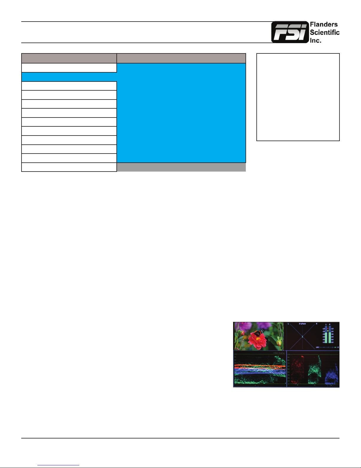
OSC Mode (LM-0750W Only)
Activating this mode, only available on the LM-0750W, will generate a quad
viewing mode with 2 Scopes of your choice (Window 1 and Window 2) as well an
Audio Phase Meter and 2 Channel Audio Level Meters in addition to a preview
window showing the active signal whenever the corresponding Scopes and VU
Meters prole is selected.
Ballistics
This allows you to select the the type of Audio Level Meters to display. You
can select from PPM Type I, PPM Type II, or True Peak.
Return to Table of Contents
22
© 2014 Flanders Scientic, Inc.
Page 23
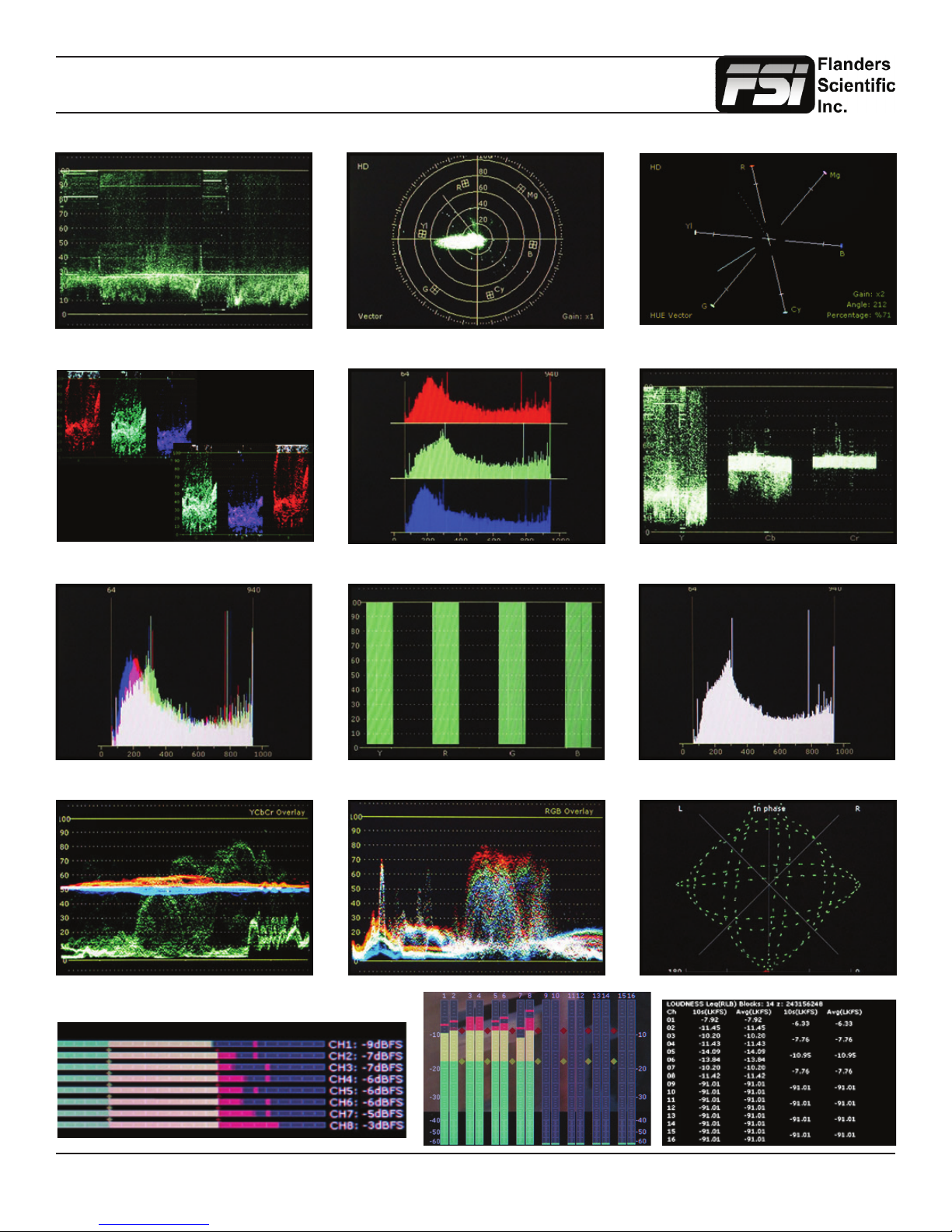
Scopes & Audio Meters
Luminance Vector Scope Hue Vector
RGB & GBR Parade Color Histogram YCbCr
RGB Histogram Column (YRGB Peak) Histogram
YCbCr Overlay RGB Overlay Audio Phase Meter
Audio Loudness
Audio Level Meters
Return to Table of Contents
23
© 2014 Flanders Scientic, Inc.
Page 24
System Menu
Main Menu System
Function DVI Selection DVI-D
Scopes & Audio Meters DVI Pixel Format Full RGB
Video Component Input COMPONENT
Audio Component Pixel Format YPbPr
Marker 3G Level B Stream 1
System SDI Hue Adjustment Off
Alarm Back Light 35
OSD Back Light Interval On
GPI LED Light On
Color Management Language English
System Status Part Display Off
Support Load Prole Default
Save Prole Prole 1
DVI Selection / DVI Pixel Format
FSI Monitors are equipped with a DVI-I Input, which supports both DVI Digital and DVI Analog sources. To select between
DVI-D (Digital) and DVI-A (Analog) simply toggle this control accordingly. Use DVI Pixel Format to select between Full RGB
(0-255), Limited RGB (16-235), or YCbCr modes.
Component Input / Component Pixel Format
Use Component Input to toggle between Component & Composite Video on the LM-0750W’s or LM-0950W’s shared analog
inputs. Use Component Pixel Format to toggle the Analog Component Video Inputs between YPbPr or RGB mode on all
models.
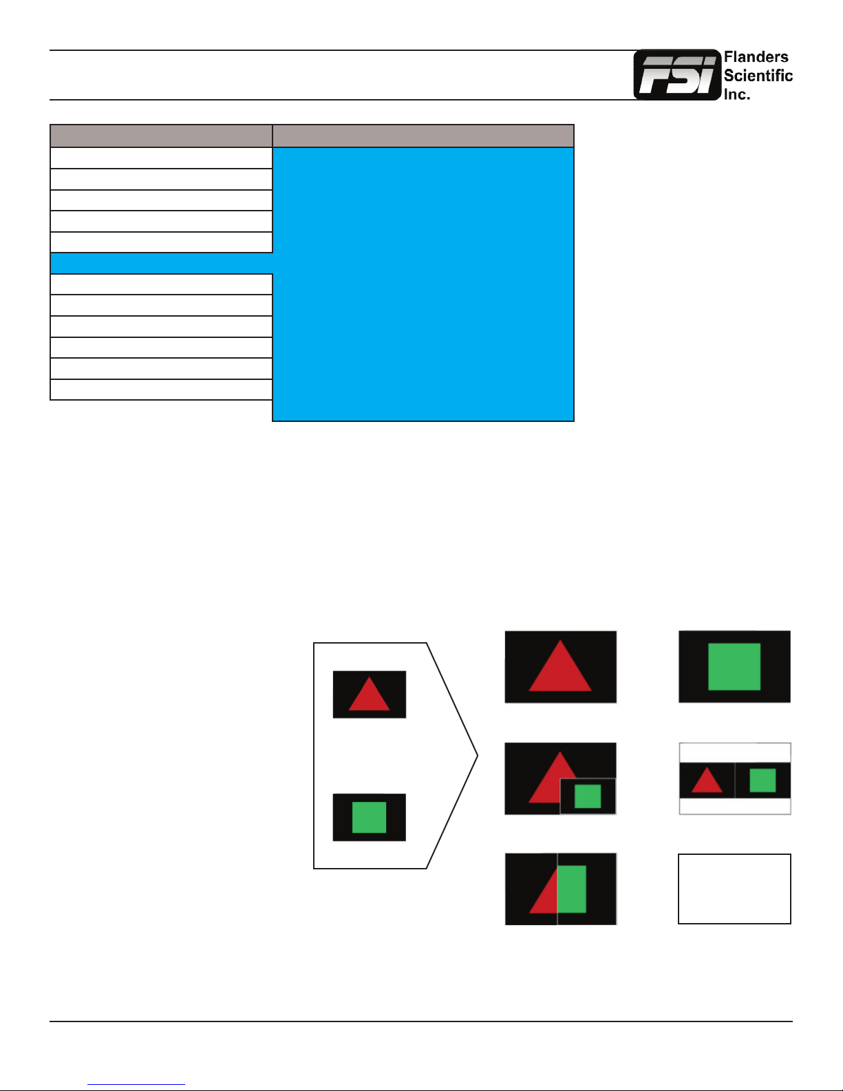
3G Level B
When monitoring a 3Gbps SDI Level B
signal (monitor must be equipped with
3Gbps SDI Inputs) comprised of two
distinct 1.5Gbps HD-SDI signals that
have been muxed together you can
use this 3G Level B selection to select
different monitoring options including:
Stream 1, Stream 2, PAP, PIP, POP,
Vertical Split, Horizontal Split, Overlay
Mode. Please note that Level B 3Gbps
SDI requires that both 1.5Gbps signals
share the same frame rate and resolution
and that Link A and Link B are genlocked.
For signals using SMPTE 425M-B image
format mapping to transport SMPTE
372M formatted Dual Link information
(4:4:4) YCbCr or RGB / 1080p50/60) the
Overlay Mode should be used to view
the combined LinkA and LinkB data as a
Link A
Picture in Picture Picture by Picture
3Gbps SDI (Level B)
Split Screen (Vert or Horiz)
Link B
Link B Full ScreenLink A Full Screen
Overlay Mode (4:4:4 or 1080p50/60)
4:4:4 SMPTE 425M-B
= 4:2:2 Link A +
0:2:2 Link B
single video signal.
Return to Table of Contents
24
© 2014 Flanders Scientic, Inc.
Page 25
System Menu
Main Menu System
Function DVI Selection DVI-D
Scopes & Audio Meters DVI Pixel Format Full RGB
Video Component Input COMPONENT
Audio Component Pixel Format YPbPr
Marker 3G Level B Stream 1
System SDI Hue Adjustment Off
Alarm Back Light 35
OSD Back Light Interval On
GPI LED Light On
Color Management Language English
System Status Part Display Off
Support Load Prole Default
Save Prole Prole 1
3G Level B 3D Monitoring Modes
FSI’s passive 3D technology 3D monitors, such as the CM500TD and CM420TD, are equipped with a circular polarizing
lter that allows signals that have been interleaved before reaching the monitor to be viewed in 3D by simply viewing the
content through passive polarized 3D glasses. However, in addition to viewing interleaved sources FSI’s 3D monitors can
also accept two full resolution sources that have been multiplexed over 3Gbps SDI and interleave them for 3D viewing. If
you have such a 3G Level B signal compromised of full resolution left and right eye channels you can select Line by Line
from the 3G Level B Menu selection, which will instruct the monitor to interleave the sources and display them onscreen for
3D viewing through passive 3D glasses. In addition to this Line by Line mode all FSI monitors with 3Gbps SDI inputs will
have the following diagnostic modes for monitoring 3D signals without glasses:
3D Checkerboard: Checkerboard display of both signals with alternating blocks shown from Link A and Link B of the
multiplexed 3Gbps SDI signal. The checkerboard size is adjustable using the Checkerboard Size menu option.
3D Disparity: This shows an overlay of Link and Link B with differences between the links highlighted.
Stream 1, Stream 2, PAP, Horizontal Split, and Vertical Split: As with all Level B 3Gbps SDI signals these 3G Level B
viewing modes can be useful for analyzing and comparing Left and Right Eye streams.
*Helpful Tip: When viewing 3D signals on any passive 3D device try to sit as eye level to the center of the screen as
possible. Viewing from the left or right of center should not prevent proper 3D viewing, but passive 3D technology
has a very small vertical position window. If the monitor is viewed from too high or too low of a position the 3D
image will not be seen properly
PIP Input
Select the input for use with the Picture In Picture Function.
PIP Mode
Select between Picture In Picture, Picture On Picture, and Picture And Picture for the PIP Function.
Return to Table of Contents
25
© 2014 Flanders Scientic, Inc.
Page 26
System Menu
Main Menu System
Function DVI Selection DVI-D
Scopes & Audio Meters DVI Pixel Format Full RGB
Video Component Input COMPONENT
Audio Component Pixel Format YPbPr
Marker 3G Level B Stream 1
System SDI Hue Adjustment Off
Alarm Back Light 35
OSD Back Light Interval On
GPI LED Light On
Color Management Language English
System Status Part Display Off
Support Load Prole Default
Save Prole Prole 1
SDI Hue Adjustment
This option allows you to activate the HUE (PHASE) adjustment knob while monitoring in SDI. In analog monitoring modes
(i.e. Composite Video) the HUE (PHASE) adjustment will always be active. Technically speaking Serial Digital being both a
Digital and YCbCr or RGB video format should not require a HUE (PHASE) adjustment, but should you wish to have such
an adjustment in SDI you should set this option to On.
Lock Chroma/Bright/Contrast
When set to On this option will lockout the Chroma, Brightness, & Contrast knobs to help prevent accidental adjustment.
Luminance
This setting adjust peak white luminance on the display and is the correct way to increase or decrease overall display
luminance (not the brightness knob).
Luminance Interval
The luminance interval is a power saving feature; It allows you to specify the amount of time without an active signal being
shown on the monitor that should be allowed to expire before the monitor’s backlight (if applicable) is turned off to reduce
the power consumption of the unit. When placed in the On position the monitor will not enter the power saving mode and
will keep the backlight on so long as the monitor is left on.
LED Light
Allows you to turn off the LED lights on the Monitor’s Keypad.
UDisk Mode
As of rmware version 9.53-1907 or later you can set this to ON, now the default, to allow your monitor to permanently
remain in update mode. When on you can simply plug your monitor into any compatible computer with the provided USB to
RJ-45 update cable and it will be recongized as a USB mass storage device for transfer of new rmware and/or 3D LUTs.
This should only be turned OFF when using GPI control.
Part Display
Toggles whether just the center part (On) or entire source (Off) is shown in Sub Window Mode.
Load Prole
Recall Saved Prole Settings. Highlight desired prole & press ENTER to activate the saved prole selection.
Save Prole
Saves all current monitor settings under a recallable prole by highlighting Prole number & pressing ENTER.
Return to Table of Contents
26
© 2014 Flanders Scientic, Inc.
Page 27
Alarm Menu
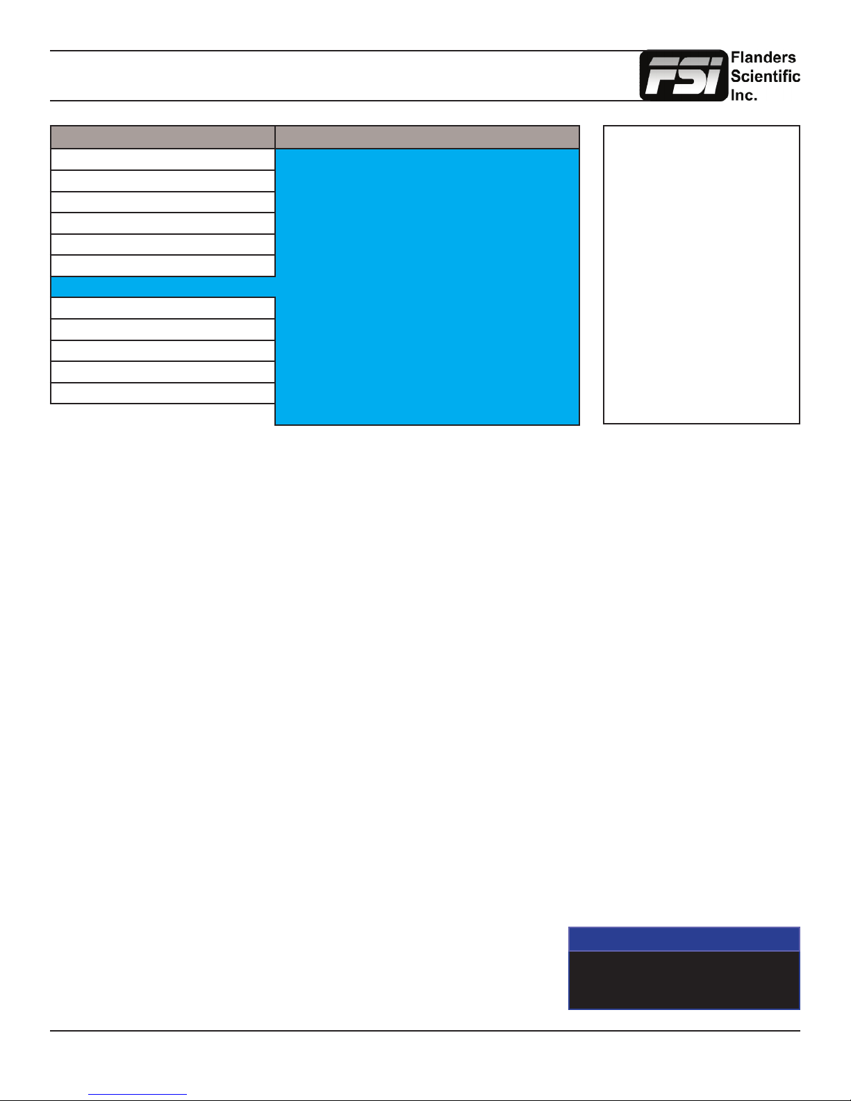
Main Menu Alarm
Function Alarm Off
Scopes & Audio Meters Visual Alarm Off
Video Remote Alarm Monitoring Off
Audio IRE Trigger Level 100 IRE
Marker Audio Trigger Time 5s
System UMD Display UMD
Alarm UMD Color White
OSD UMD Position Bottom
GPI Audio Meter Vertical
Color Management Select Alarm Area
System Status RS422 Address 1
Support Baud Rate 9600
Parity None
The monitor’s built in Alarm system allows for simplied QC monitoring of signals with minimal overlap of active video.
The alarm monitoring system allows you to specify alarm parameters that will trigger onscreen and/or remotely monitored
warnings when a specied condition is met. This feature provides an unobtrusive QC viewing mode compared to having
onscreen scopes active at all times. Please note the alarm monitoring capabilities are limited by the processing power of
the monitor. The signal will be sampled at a variable rate depending on other processing loads placed on the monitor. With
minimal additional processing demands the fastest sample rate is approximately every 2 to 3 frames. It is therefore possible
that an alarm event occurring for only 1 or 2 frames may be missed by the alarm monitoring system. The alarm monitoring
system is a useful tool for quick analysis of content to make sure no serious errors exist, but it should not be used as
substitute for standalone legalizers and signal level monitoring systems in ultra-critical level monitoring applications.
NOTE: Onscreen Alarms are
processing power intensive.
When active the monitor may
respond more slowly to user
input via buttons/remote control
if a large number of successive
alarm events are occurring.
Switching to an unused input with
no video will allow the monitor
to respond quickly to user input
should the operator simply want
to turn Alarm monitoring off in
scenarios where monitor menu
response is slowed by such
successive alarm events.
Alarm
Selects the type of alarm events that will be monitored. This selection only affects onscreen (visual) alarms and does not
change what alarm events can be monitored through the remote control alarm monitoring software.
Safety Alarm: Will trigger an alarm if a loss of signal is detected, a full black eld is detected, a full blue eld is detected,
and/or embedded audio goes mute for the amount of time specied in the Audio Trigger Time setting. The audio mute
alarm will only trigger if audio is being embedded into the signal and is mute for the specied amount of time, there will
be no audio mute warning if audio is not being embedded into the SDI signal.
Safety Video Alarm: Same as Safety Alarm minus audio alarms.
IRE Alarm: Will trigger an alarm if the IRE level specied in the IRE Trigger Level setting is exceeded.
RGB Alarm: Will trigger an alarm if any RGB Levels exceed 100 IRE.
IRE & RGB Alarm: Combines IRE and RGB Alarms and will trigger an alarm if either or both exceed their set parameters.
All Alarms: Will trigger an alarm if any alarm condition is met (Loss of Signal, Black Field, Blue Field, Audio Mute, IRE
threshold exceeded, RGB levels over 100 IRE).
Visual Alarm
When set to ON a small box will appear on the monitor’s screen whenever the
alarm condition set in the Alarm menu selection explained above is triggered.
Alarm
IRE
Return to Table of Contents
27
© 2014 Flanders Scientic, Inc.
Page 28
Alarm Menu
Main Menu Alarm
Function Alarm Off
Scopes & Audio Meters Visual Alarm Off
Video Remote Alarm Monitoring Off
Audio IRE Trigger Level 100 IRE
Marker Audio Trigger Time 5s
System UMD Display UMD
Alarm UMD Color White
OSD UMD Position Bottom
GPI Audio Meter Vertical
Color Management Select Alarm Area
System Status RS422 Address 1
Support Baud Rate 9600
Parity None
Remote Alarm Monitoring
When set to ON allows for remote alarm monitoring via FSI’s remote alarm monitoring software.
IRE Trigger Level
Sets the luminance threshold at which IRE alarms will be triggered, adjustable from 90 to 109 IRE
Audio Trigger Time
Sets the amount of time with mute audio that should elapse before the mute audio alarm is triggered.
Select Alarm Area
The screen area monitored for Alarm Triggers can be adjusted using the Select Alarm Area feature. To set the alarm area
simply highlight Select Alarm Area and press ENTER. Once active you can use the monitor’s rotary knobs to adjust 4 lines
on screen, similar to the custom graticules feature on the marker menu, to dene the onscreen area that will be monitored.
Once your desired area has been set simply use the MENU button to back out of the Select Alarm Area function. The default
alarm monitoring area is the whole screen, but this function allows users to specify smaller regions if only a portion of the
screen area needs to be monitored.
UMD Display
Only applies to Safety Broadcast feature. Allows you to select whether the Source ID overlay displayed is based on the
manually set source ID on the monitor’s OSD menu or based on remotely set UMD information over RS232 or RS422. You
may also turn the selection to off to remove the Source ID overlay.
UMD Color
Only applies to Safety Broadcast feature. Toggles the Source ID text color between White and Black.
UMD Position
Only applies to Safety Broadcast feature. Select top or bottom of screen. Please note that when Timecode Overlay is active
the UMD will automatically be positioned at the bottom of the screen.
Audio Meter
Only applies to Safety Broadcast feature. Determines position of 2 channel audio level meters. Select from Horizontal or
Vertical.
RS422 Address
Sets the monitors RS422 address for remote control and alarm monitoring. Set between 0~126.
Return to Table of Contents
28
© 2014 Flanders Scientic, Inc.
Page 29
Alarm Menu
Main Menu Alarm
Function Alarm Off
Scopes & Audio Meters Visual Alarm Off
Video Remote Alarm Monitoring Off
Audio IRE Trigger Level 100 IRE
Marker Audio Trigger Time 5s
System UMD Display UMD
Alarm UMD Color White
OSD UMD Position Bottom
GPI Audio Meter Vertical
Color Management Select Alarm Area
System Status RS422 Address 1
Support Baud Rate 9600
Parity None
Baud Rate
Sets the RS422 baud rate. This should be left at the default 9600 value unless otherwise specied by Flanders Scientic’s
support department.
Parity
Sets Parity for RS422 communication. This should be left at the default None position unless otherwise specied by Flanders
Scientic’s support department.
Return to Table of Contents
29
© 2014 Flanders Scientic, Inc.
Page 30
OSD Menu
Main Menu OSD
Function Status Display 5 Sec.
Scopes & Audio Meters Menu Pos. Top Right
Video Status Pos. Top Left
Audio Rotary Pos. Bottom
Marker Source ID Off
System Source ID Position Bottom
Alarm Source ID Character CAM1
OSD Time Code VITC1
GPI Time Code Size Small
Color Management Time Code Position Top
System Status
Support
Status Display
Toggles settings for pop up window indicating resolution and frame rate of source when input button is pressed or a new
signal type is routed to monitor. Setting this option to Off turns the Status Display function completely off, setting to 5 Sec.
enables a 5 second onscreen status display when the input button is pressed or source format is changed, and setting to
On leaves the Status Display onscreen permanently.
Menu Pos.
Changes position of onscreen menu between three choices: Center, Top Left, or Top Right.
Status Pos.
Changes position of onscreen status display window. Select from Top Left, Top Right, Bottom Left, Bottom Right, or Center.
Rotary Pos.
Changes position of onscreen window indicating status of any rotary knob (Volume, Contrast, etc.) during adjustment.
Select from Top, Center, or Bottom.
Source ID
Allows you toggle source ID function on/off. The Source ID function can be used to set a manual onscreen label of up to 5
characters. This is often used to allow for the labeling of a monitor as PGM, PVM, CAM, etc. without using placards or tape.
Source ID Position
Changes position of onscreen Source ID function.
Source ID Character
Allows you to customize text for Source ID label using ENTER, UP, and DOWN buttons.
Time Code
Allows you to select whether to display Time Code on screen pulled from an HD/SD-SDI signal. Select between Off, LTC,
VITC 1, or VITC 2. Please note that Time Code cannot be displayed at the same time as Scopes, Markers, or other onscreen
ancillary functions.
Time Code Size
Allows you to toggle between Large or Small Timecode Display.
Time Code Position
Use this toggle to change the onscreen position of Time Code.
Return to Table of Contents
30
© 2014 Flanders Scientic, Inc.
Page 31
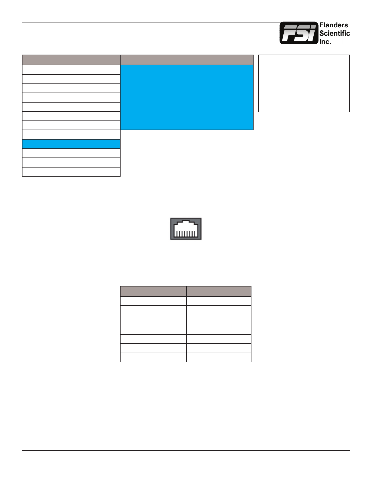
GPI Menu
Main Menu GPI
Function GPI 1 Keyboard Locking
Scopes & Audio Meters GPI 2 SDI 2 Input
Video GPI 3 Red Tally
Audio GPI 4 Green Tally
Marker GPI 5 UNDEF
System GPI 6 Toggle Back Light
Alarm GPI 7 DVI Input
OSD
GPI
Color Management
System Status
Support
This menu allows you to set 7 assignable functions for remote control via the GPI interface on the back of the monitor (RJ45 connector labeled GPI). Simply select one of the GPI slots, 1 through 7, and press ENTER to generate a list of available
functions that can be toggled using the GPI interface.
NOTE: As of rmware version
9.53-1907 or later you must set
the UDisk Mode (System Menu)
to OFF in order to use the GPI
Contact Closure port for remote
control.
87654321
When looking at the GPI RJ-45 Connector located on the back of the monitor the pins are arranged 1 through 8 from right to
left. This GPI interface is a contact closure based system and PIN 5 is always the ground. The GPI numbering on the GPI
menu corresponds to the physical Pin assignments as follows:
Menu RJ-45 Pin
GPI 1 Pin 1
GPI 2 Pin 2
GPI 3 Pin 3
GPI 4 Pin 4
GPI 5 Pin 6
GPI 6 Pin 7
GPI 7 Pin 8
To prevent conicts between menu toggles and GPI commands some features such as the marker selection toggle must be
set to GPI in their respective menus (i.e. Marker Menu) in order to function properly.
If using FSI’s GPI Keypad Lock to lockout the monitor’s keypad or menu the corresponding Keyboard Locking or Menu
Locking function must be set to GPI 1.
Return to Table of Contents
31
© 2014 Flanders Scientic, Inc.
Page 32
Audio Menu
Main Menu Audio
Function SDI 1 Audio Digital CH1&2
Scopes & Audio Meters SDI 2 Audio Digital CH1&2
Video Component Audio Analog
Audio CVBS Audio Analog
Marker DVI-D Audio Analog
System DVI-A Audio Analog
Alarm Audio Sync Signal Clock
OSD Audio Lockout Off
GPI
Color Management
System Status
Support
SDI 1 Audio
Allows you to select what audio source should be active (audible) when SDI 1 is the selected video input. You may select
any single channel or stereo pair of embedded audio (i.e. Digital Channel 1, 1&2, 3&4, etc.), Analog Audio (from minijack
input), or No Sound. The active stereo pair selected here will be the stereo pair shown when the Audio Phase Meter is
activated on the SDI 1 Input.
SDI 2 Audio
Allows you to select what audio source should be active (audible) when SDI 2 is the selected video input. You may select
any single channel or stereo pair of embedded audio (i.e. Digital Channel 1, 1&2, 3&4, etc.), Analog Audio (from minijack
input), or No Sound. The active stereo pair selected here will be the stereo pair shown when the Audio Phase Meter is
activated on the SDI 2 Input.
NOTE: All FSI Monitors can
monitor embedded audio in
SD-SDI, HD-SDI, and 3G-SDI
signals. However, on LM series
units 3G-SDI audio monitoring is
only possible over 3Gbps Level
A signals, not Level B signals.
All CFE2 equipped units can
monitor 3G Level A and Level B
audio.
Component Audio
Allows you to select between Analog Audio input (via minijack connector) or No Sound when Component Video is the
selected video input.
CVBS Audio
Allows you to select between Analog Audio input (via minijack connector) or No Sound when Composite Video is the
selected video input.
DVI-D Audio
Allows you to select between Analog Audio input (via minijack connector) or No Sound when DVI-Digital is the selected
video input. On monitors shipped AFTER October 27th, 2014 you can also use the Channel 1 & 2 selection listed here for
stereo HDMI audio support when using a HDMI or Display Port to DVI cable.
DVI-A Audio
Allows you to select between Analog Audio input (via minijack connector) or No Sound when DVI-Analog is the selected
video input.
Audio Sync
Choose between Signal Clock or Internal Clock for Audio Sync. Some embedded audio sources may have a poor quality
signal clock that may lead to audio distortion. Switching to Internal Clock can help to eliminate or minimize such distortion.
Audio Lockout
When set to On this feature will lock the Volume Knob, which retains the last used audio setting used. While On no
adjustments to Audio volume will be possible.
Return to Table of Contents
32
© 2014 Flanders Scientic, Inc.
Page 33
Color Management Menu
Main Menu Color Management
Function Start Display Alignment
Scopes & Audio Meters Reset Factory Alignment
Video Red Gain 50
Audio Green Gain 50
Marker Blue Gain 50
System Red Bias 50
Alarm Green Bias 50
OSD Blue Bias 50
GPI Color Space Rec 709
Color Management Video Clipping Off
System Status Update Firmware
Support
NOTE: All FSI Monitors are precisely
calibrated before shipping with NIST
traceable color analyzers specically
setup to measure the model in
question. However, if you would
manually like to adjust the white
balance of the monitor you may do
so by using the RGB Gain and Bias
adjustment. Please DO NOT use the
Reset Factory Alignment or Start
Display Alignment functions unless
asked to do so by an authorized
FSI service representative. For
uorescent backlight equipped
monitors a warm-up period of 30 to
60 minutes should be allowed before
making adjustments.
Start Display Alignment
Used at the factory level or with the CA310 DCAA kit. Not used for 3D LUT based calibration with third party calibration
software.
Reset Factory Alignment
The password protected Reset Factory Alignment option is for use by FSI and/or authorized FSI service centers only. This
option does not reset your monitor to factory default mode, but rather deletes factory calibration data. To reset to factory
default mode go to the System Menu, select Load Prole, select Default, and then conrm by pressing enter.
Red/Green/Blue Gain & Bias
These settings allow you to manually adjust the white balance of the monitor. We suggest using a 100% white eld for Gain
adjustment and a 30 to 40IRE grey eld for Bias adjustment.
Color Space
The new BM & CM series monitors & CM-170W, LM-2450W (wiht CFE), LM-2460W, LM-2461W, & LM-2470W are equipped
with the FSI Color Fidelity Engine and have the ability to work in several different color spaces. Select from available options
to instantly change the active color space. Please note that switching to DCI P3 may take up to 10 seconds.
Color Matching (Alternate CMF Selection for OLED Monitors)
FSI’s OLED monitors are capable of operating with calibration based on the standard CIE 1931 Color Matching Function
(CMF) or the Judd Modied CMF, which has largely become the preferred CMF for use with OLEDs. As the Judd Modied
CMF is an easy to apply known offset from CIE 1931 for any given display type you can easily toggle between these without
having to recalibrate the monitor. This also allows for calibration using software and equipment based on the the more
common CIE 1931 CMF with the ability to quickly and easily apply the Judd based offset after calibration is complete.
Video Clipping
Setting Video Clipping to On will clip all levels exceeding legal broadcast limits. With Video Clipping on you can see how
source content will look if clipped within legal broadcast limits. Setting Video Clipping to Off will show you the full range of
levels onscreen, this is the recommended operating mode.
Return to Table of Contents
33
© 2014 Flanders Scientic, Inc.
Page 34
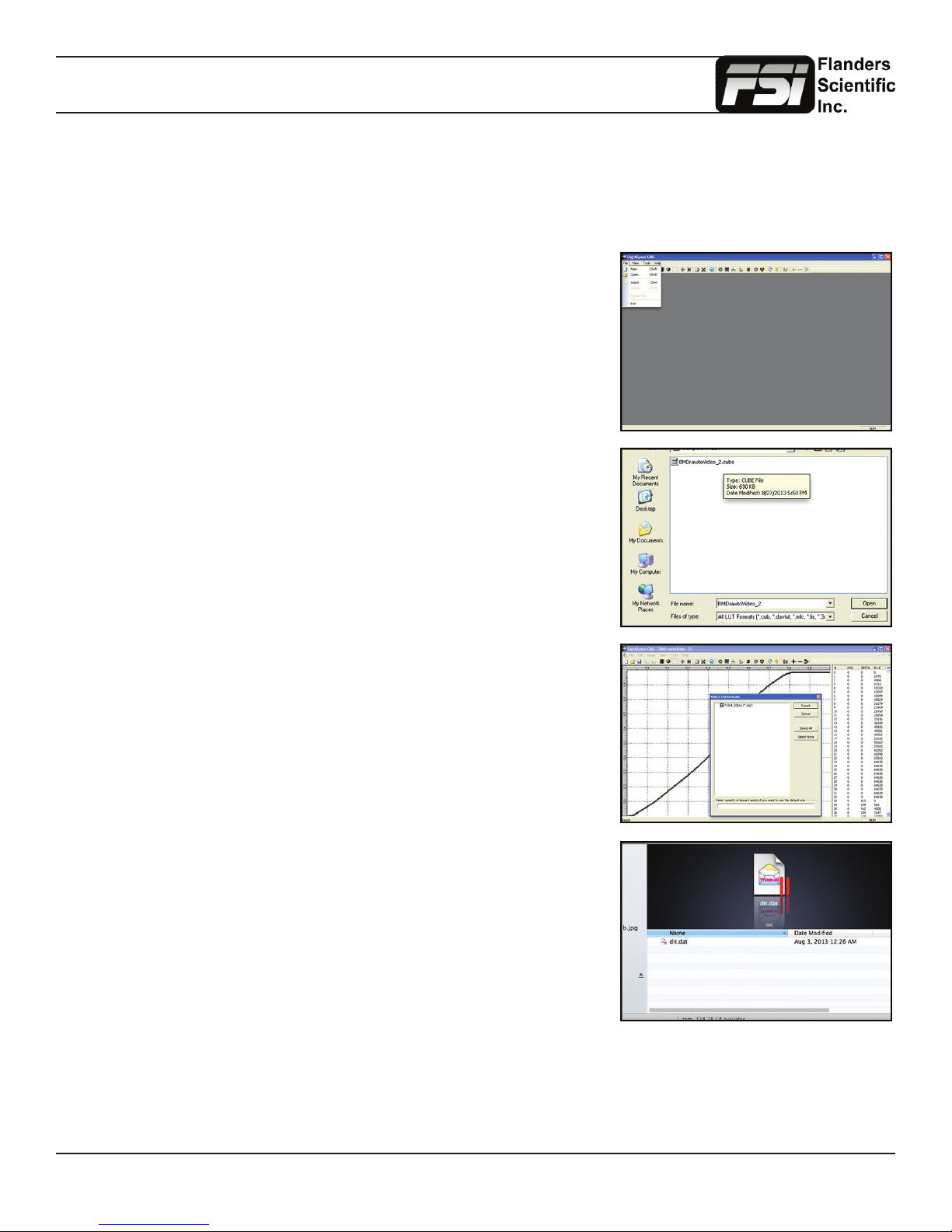
Color Management Menu
DIT LUTs
As of rmware update 1.0.00-1958, CFE 2 equipped monitors are capable of loading multiple custom DIT LUTs which do not
require you to prole the panel. You can use Lattice, the main component of Light Illusion’s LightSpace, or LightSpace FSI
LUTs software to convert and export LUTs in the FSI format. The LightSpace workow is shown below.
Open LightSpace CMS
Select File \ Import \ YourLUT
Select File \ Export \ Choose FSI17_32bits (*.dat) as the export format.
In Lattice you should select .dat V2 as the export type.
Once the le is saved, change the le name to ditXX.dat where XX is a 2 digit
number ranging from 00 to 16. The monitor can store up to 16 DIT LUTs at a
time. The naming structure is ditXX.dat with valid LUT names ranging from
dit01.dat to dit16.dat.
Return to Table of Contents
34
© 2014 Flanders Scientic, Inc.
Page 35
Color Management Menu
Verify that the monitor’s update mode is turned on via the System Menu:
System -> UDisk Mode -> On
Connect the FSI update cable that came with your monitor (USB to RJ45) to an
available USB port on your computer.
After a short time, the computer should recognize the FSI monitor as a mass storage
device, viewable in Mac’s Finder or PC’s My Computer.
Drag and drop the ditXX.dat le(s) you created to the monitor. All 16 DIT LUTs can be
transfered at one time.
System
LED Light On
UDisk Mode On
DHCP On
Select Menu \ Color Management \ Update LUT to save the LUT(s).
Once saved the DIT LUTs can be turned on/off by assigning DIT 3D LUT to a funciton
key.
The active 3D LUT that is enabled by the function key can be selected with the DIT 3D
LUT Channel Selection on the Color Management Menu.
As of rmware version 1.0.00_1960 you can also simply use the up and down arrow
keys while the DIT LUT funciton is active to toggle between 3D DIT LUTs you have
loaded to the monitor.
NOTE: When a DIT LUT is active it will impact the Scope and Measurement feature
values accordingly to reect your DIT LUT’s impact on the signal. This is in contrast
to the simpler Log mode selections found on the Video menu, which will not change
scope or measurement values even when active.
Color Management
Red Bias 50
Green Bias 50
Blue Bias 50
Color Space Rec 709
Video Clipping Off
Lut Bypass None
Update LUT ----
DIT 1D LUT Channel 1
DIT 3D LUT Channel 1
Return to Table of Contents
35
© 2014 Flanders Scientic, Inc.
Page 36
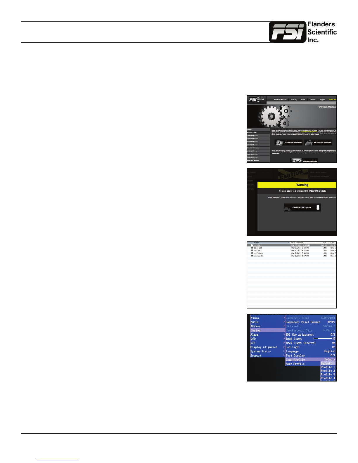
Color Management Menu
Custom Calibration LUTs
Starting with Firmware 0.9.49, FSI models equipped with the Color Fidelity Engine are capable of loading custom calibration
3D LUTs. This advanced feature requires use of color management software (such as Light Illusion’s LightSpace CMS or
SpectraCal’s CalMAN, both of which are currently supported) and a professional grade probe. The steps below cover the
general process of updating LUTs on the monitor.
Check your monitor’s rmware version by accessing System Status from the Main
Menu. If necessary, update your FSI CFE equipped monitor to rmware version 9.50
or newer. Firmware updates and instructions can be found at FlandersScientic.com.
If you already have rmware 9.50 or newer and the supporting CFE les installed
on your monitor, skip ahead to Page 38: Generating Custom LUTs.
Download the latest CFE distribution package from the Firmware section of
FlandersScientic.com.
Select your monitor’s model from the left hand side and then click on the download link.
A verication box will appear with a warning about downloading the correct update for
your model of monitor.
The download will be a zip le containing a code le, and data les related to each
color space.
Unzip this le on your computer.
Load the default prole on the monitor.
Menu \ System \ Load Prole \ Default
Hit ENTER and conrm with Yes.
Return to Table of Contents
36
© 2014 Flanders Scientic, Inc.
Page 37
Color Management Menu
After the monitor has loaded the prole and restarted, turn the monitor off by using the
POWER button on the keypad.
Connect the FSI update cable that came with your monitor (USB to RJ45) to the GPI
port on your monitor.
If you misplaced your update cable, they are available from ShopFSI.com.
Verify that the monitor’s update mode is turned on via the System Menu:
System -> UDisk Mode -> On
Connect the FSI update cable that came with your monitor (USB to RJ45) to an
available USB port on your computer.
After a short time, the computer should recognize the FSI monitor as a mass storage
device, viewable in Mac’s Finder or PC’s My Computer.
Drag and drop the downloaded (unzipped) CFE les to the monitor. It will take a few
moments to transfer.
It is important to transfer ALL of the new downloaded CFE les to the monitor.
System
LED Light On
UDisk Mode On
DHCP On
Return to Table of Contents
37
© 2014 Flanders Scientic, Inc.
Page 38
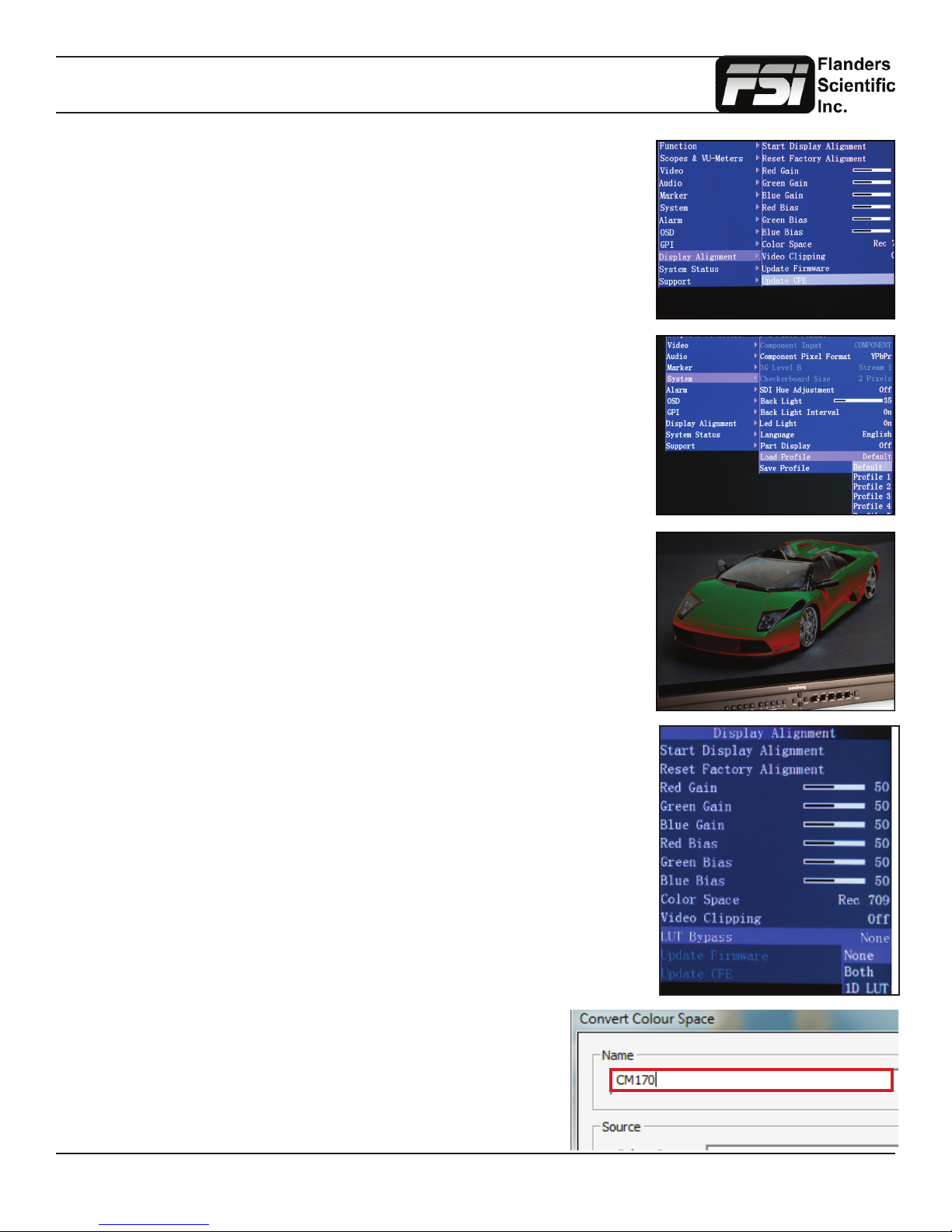
Color Management Menu
Once the les have nished transferring, on the monitor go to:
Menu \ Color Management \ Update LUT
Press ENTER to begin the process, and conrm with Yes when the monitor prompts
you.
The update process can take several minutes. Upon completion of the LUT transfer,
power cycle the monitor and load the default prole.
Menu \ System \ Load Prole \ Default
Hit ENTER and conrm with Yes.
Note: If you notice image solarization, the CFE update did not complete correctly. It
may be necessary to repeat this process.
Loading Custom Calibration LUTs
If you are now running rmware version 9.50 or later you can follow the steps outlined
below to load a custom calibration LUT to the monitor. For guidance on proling a monitor with a third party program that outputs LUTs in a compatible FSI LUT format please
see the program specic instructions for the solution you are using. The instructions in
this manual will only cover pre-proling setup and how to load a completed 3D LUT to
the monitor.
In the Color Management menu, set LUT Bypass to 3D LUT, effectively placing the
monitor in Wide Gamut mode and bypassing the factory 3D LUTs. The monitor should
be placed in this mode before proling with any third party solution.
Special Notes for OLED Monitors
We suggest setting the Color Matching Function (CMF) selection to CIE 1931 for
proling and 3D LUT creation. Once calibration is complete you can switch to Judd
modied if you prefer to operate with a Judd modied CMF based calibration. Please
note the Judd Mode selection adds a slight delay to signal locking speed when switching
sources.
When using LightSpace to generate custom user LUTs for FSI monitors, the
colorspace image name typed into the Convert Color Space Window MUST
match the monitor model name. Valid Model Names: LM-2461W, BM210, BM230,
CM170, CM171, CM172, CM240, CM250, CM320TD, CM500TD
Once you’ve generated your custom LUT, You must rename
the .dat le saved by the third party program to “user1”,
“user2”, or “user3” if not already named this way before you
attempt to import it.
Return to Table of Contents
38
© 2014 Flanders Scientic, Inc.
Page 39
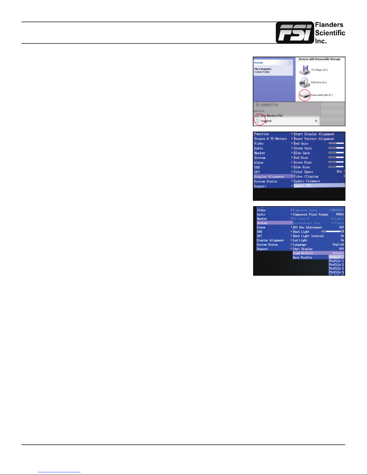
Color Management Menu
Drag and drop the custom LUT les to the monitor. It will take a few moments to
transfer.
You may load up to three custom LUTs at a time. (“user1”, “user2”, and “user3”)
Once the le has nished transferring, on the monitor go to:
Menu \ Color Management \ Update LUT
Press ENTER to begin the process, and conrm with Yes when the monitor prompts
you.
The update process will take approximately 6 minutes per LUT on monitors with rst
generation CFE boards and about 15 seconds per LUT on units with CFE2 boards.
Upon completion of the LUT transfer, power cycle the monitor.
Custom LUTs can be accessed from the Color Management menu by selecting Color
Space: USER1, USER2, USER3. Press ENTER to conrm your selection.
Monitors with a rst generation CFE board (LM-2461W, LM-2460W, CM-170W) utilize the .dat LUT format for calibration
LUTs.
Monitors with a second generation CFE board (CFE2) running rmware version 9.53-1935 or later utilize a .cfe LUT format
for calibration LUTs and a .dat LUT format for DIT LUTs. Units with CFE2 boards include:
-CM171
-CM172
-CM240
-CM250
-CM320TD
-CM420TD
-CM500TD
-BM090
-BM210
-BM230
Return to Table of Contents
39
© 2014 Flanders Scientic, Inc.
Page 40
Troubleshooting Guide
Problem Solution Notes
Image has a heavy green or magenta
cast over DVI
Image has a heavy green or magenta
cast over SDI
Too much video processing delay On the Video Menu make sure Show
Function button not responding Reload Default Prole (System Menu
Rotary knob not responding Disable any active functions. To acti-
Set DVI Pixel Format selection on System Menu to match your signal format
(RGB or YCbCr)
Set SDI Format to match your signal
type. This is found at the bottom of the
Video Menu.
PsF as is set to Interlaced. For further
reduction in processing delay set Pro-
cessing to Fast Mode on the Video
Menu.
Processing speed in all modes is a set
interval of the frame rate so the higher
your frame rate is the lower your delay
will be in milliseconds. For this reason
if your camera is capable of independent recording and monitor out frame
rates a 50 or 60Hz monitor output will
provide the lowest possible delay.
-> Load Prole -> Default)
If you have custom settings selected
that you want to retain please make
sure to take note of those custom
settings or save them to a Prole (1
through 5) for future reference as re-
loading the default prole will reset all
custom settings to factory default.
vate the Phase rotary knob in SDI set
SDI Hue Adjustment to On from Sytem
Menu. Ensure the Lock Chroma/Bright/
Contrast setting is set to Off on the
System .
A heavy green cast to the image typically means you are feeding the monitor a YCbCr signal, but have the DVI
Pixel Format Selection set to RGB. A
heavy Magenta cast to the image typically means you are sending RGB to
the monitor, but have DVI Pixel Format
set to YCbCr.
FSI monitors detect payload ID, if present, and automatically set the monitor
to receive RGB, YCbCr, or XYZ signals over SDI. However, if payload ID
is missing or corrupt from the source it
may be necessary to manually select
the SDI format to match your signal
type.
Setting Show PsF as to Progressive,
even if the signal is not PsF, adds signicant processing delay. Setting this
to Interlaced greatly reduces processing delay. Normal Mode processing offers the best balance between anciallary feature speed (e.g. scopes) and
video processing speed. Fast Mode
can reduce video processing even further, but pulls processing resources
away from scopes and other ancillary
features so menu artifacts and slower
scope update speeds may occur. However, there is no loss in video quality in
Fast Mode vs. Normal Mode.
If a function button is not responding it
is typically because a conicting function is active. For example if you set a
marker to a function button and enable
the marker, then reassign the marker
function button to a different feature
without turning the marker off rst the
marker will stay on screen and prevent
other functions from being activated.
Avoiding such conicts will prevent the
problem or for a quick solution you can
reload the default prole to clear the
conict.
The Phase knob is locked by default in
SDI as there is no phase to adjust in a
digital component signal. Rotary knobs
may serve secondary purposes (e.g.
Vector Scope Gain) or may be inaccessible with certain functions active.
Return to Table of Contents
40
© 2014 Flanders Scientic, Inc.
Page 41
Troubleshooting Guide
Problem Solution Notes
Progressive signal looks interlaced
and/or there are unexpected lines on
screen.
External audio leads video Ensure that the ‘Show PsF as’ option
Image is ickering On OLED units verify that Flicker Free
Image not as sharp as desired Adjust sharpness level from the Video
Scopes refreshing slowly Displaying 1 scope window instead of
Ensure that you are sending the monitor a true progressive signal, not PsF.
You can verify whether the signal is PsF
or P from the System Status Menu. The
monitor will indicate PsF or P accordingly. If PsF is your only output option
you can set Show PsF as to Progressive on the Video Menu.
on the Video Menu is set to Interlaced,
even if your signal is not PsF. This will
greatly reduce video processing delay.
Setting Processing to Fast Mode on
the Video Menu can further reduce video delay.
Mode is turned ON. With all monitors
verify the frame rate being received on
the System Status menu. If interlaced
or PsF the icker may be normal and
part of the signal. Feeding the montior
progressive instead of PsF or setting
Show PsF as to Progressive instead of
interlaced may further eliminate icker.
Menu or use the Max Sharpness function.
2 will greatly increase scope update
speed. Normal update speed with a
single scope active is approximatley
every other frame.
Setting show PsF as to Progressive,
instead of interlaced, adds processing
delay to the signal so if at all possible
feeding the monitor a true progressive
signal is preferred.
You can also use the monitor’s audio
out to ensure perfect audio/video sync
as disembedded audio is always delayed by the exact amount of video
procesing time.
No artical dithering or image enhancement is applied to the image by default.
Scope refresh rate is governed by
avaialble processing power.
Return to Table of Contents
41
© 2014 Flanders Scientic, Inc.
Page 42
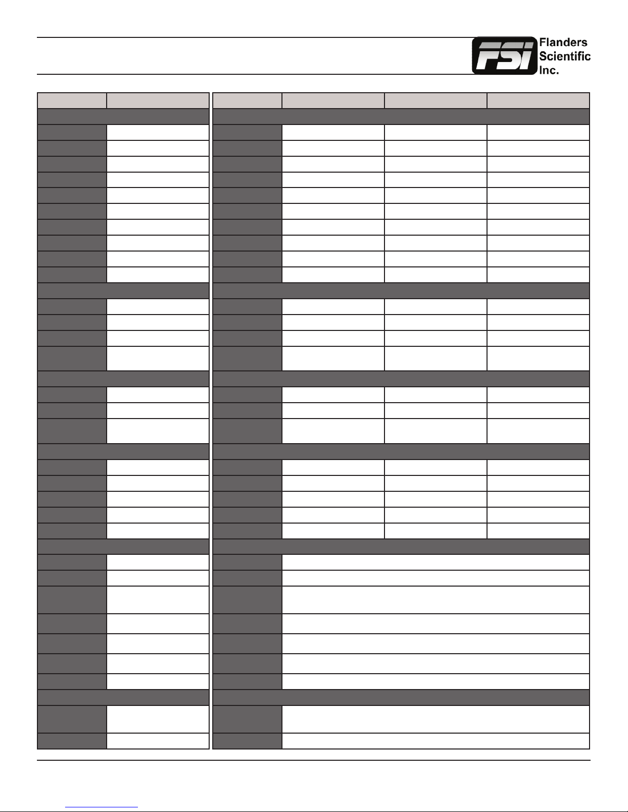
Monitor Specications
LM Series
Panel Specications
Screen Size 7”
Resolution 800x480
Aspect Ratio 15:9
Bit Depth (Colors) 8 (16.7M)
3D Polarizing Filter No
Processing 12 Bit
Contrast Ratio 500:1
Backlight White LED
Max Luminance 300nit
Viewing Angle 160°
Inputs
1x DVI-I DVI-I (Analog/Digital)
2x BNC 3gbps/HD/SD-SDI
1x BNC Composite
3x BNC Component
Outputs
2x BNC N/A
1x BNC 3Gbps/HD/SD-SDI
3x BNC N/A
LM-0750W
(YPbPr/RGB)
BM Series
Panel Specications
Screen Size 9” 21.5” 23”
Resolution 1920x1080 1920x1080 1920x1080
Aspect Ratio 16:9 16:9 16:9
Bit Depth (Colors) 8 (16.7M) 8 (16.7M) 8 (16.7M)
3D Polarizing Filter No No No
Processing 12 Bit 12 Bit 12 Bit
Contrast Ratio 750:1 1000:1 1000:1
Backlight White LED White LED White LED
Max Luminance 250nit 250nit 250nit
Viewing Angle 178° 178° 178°
Inputs
1x DVI-I DVI-I (Analog/Digital) DVI-I (Analog/Digital) DVI-I (Analog/Digital)
2x BNC 3Gbps/Dual Link/HD/SD-SDI 3Gbps/Dual Link/HD/SD-SDI 3Gbps/Dual Link/HD/SD-SDI
1x BNC N/A Composite Composite
3x BNC N/A Component
Outputs
2x BNC 3Gbps/Dual Link/HD/SD-SDI 3Gbps/Dual Link/HD/SD-SDI 3Gbps/Dual Link/HD/SD-SDI
1x BNC N/A Composite Composite
3x BNC N/A Component
BM090 BM210 BM230
(YPbPr/RGB)
(YPbPr/RGB)
Component
(YPbPr/RGB)
Component
(YPbPr/RGB)
Audio
Audio Disembedding Ye s
Audio Level Meters Yes
Internal Speakers 2
Audio In N/A
Audio Out 1 Mini-Phono
Supported SDI Formats
ITU-R BT.656 (PAL) 576i (50)
SMPTE-125M 480i (59.94)
SMPTE-274M 1080i (60/59.94/50) 1080p
SMPTE-296M 720p
2K 2048x1080 (23.98PsF/24Ps-
SMPTE-372M N/A
SMPTE-425M Standard (Level A & B)
Supported DVI Formats
DVI-A & DVI-D VGA (640x480), NTSC (720x480),
DVI Digital Only 1280x720, 1440x900, 1920x1080
(30/29.97/25/24/24Ps-
F/23.98/23.98PsF)
(60/59.94/50/30/29/25/24/23.98)
F/23.98p/24p)
SVGA (800x600), XGA
(1024x768), SXGA (1280x1024)
Audio
Audio Disembedding Ye s Ye s Ye s
Audio Level Meters Yes Yes Ye s
Internal Speakers 2 2 2
Audio In N/A 1 Mini-Phono 1 Mini-Phono
Audio Out 1 Mini-Phono 1 Mini-Phono 1 Mini-Phono
Supported SDI Formats
ITU-R BT.656 (PAL) 576i (50)
SMPTE-125M 480i (59.94)
SMPTE-274M
SMPTE-296M 720p (60/59.94/50/30/29/25/24/23.98)
2K 2048x1080 (23.98PsF/24PsF/23.98p/24p)
SMPTE-372M 1080i (29.97/25/24/23.98) 1080p (30/29.97/25/24/23.98) 720p (60/59.94/50) 4:4:4 YCbCr, RGB
SMPTE-425M Standard (Level A & B)
Supported DVI Formats
DVI-A & DVI-D VGA (640x480), NTSC (720x480), SVGA (800x600), XGA (1024x768), SXGA (1280x1024)
DVI Digital Only 1280x720, 1440x900, 1920x1080
1080i (60/59.94/50) 1080p (30/29.97/25/24/24PsF/23.98/23.98PsF)
Return to Table of Contents
42
© 2014 Flanders Scientic, Inc.
Page 43
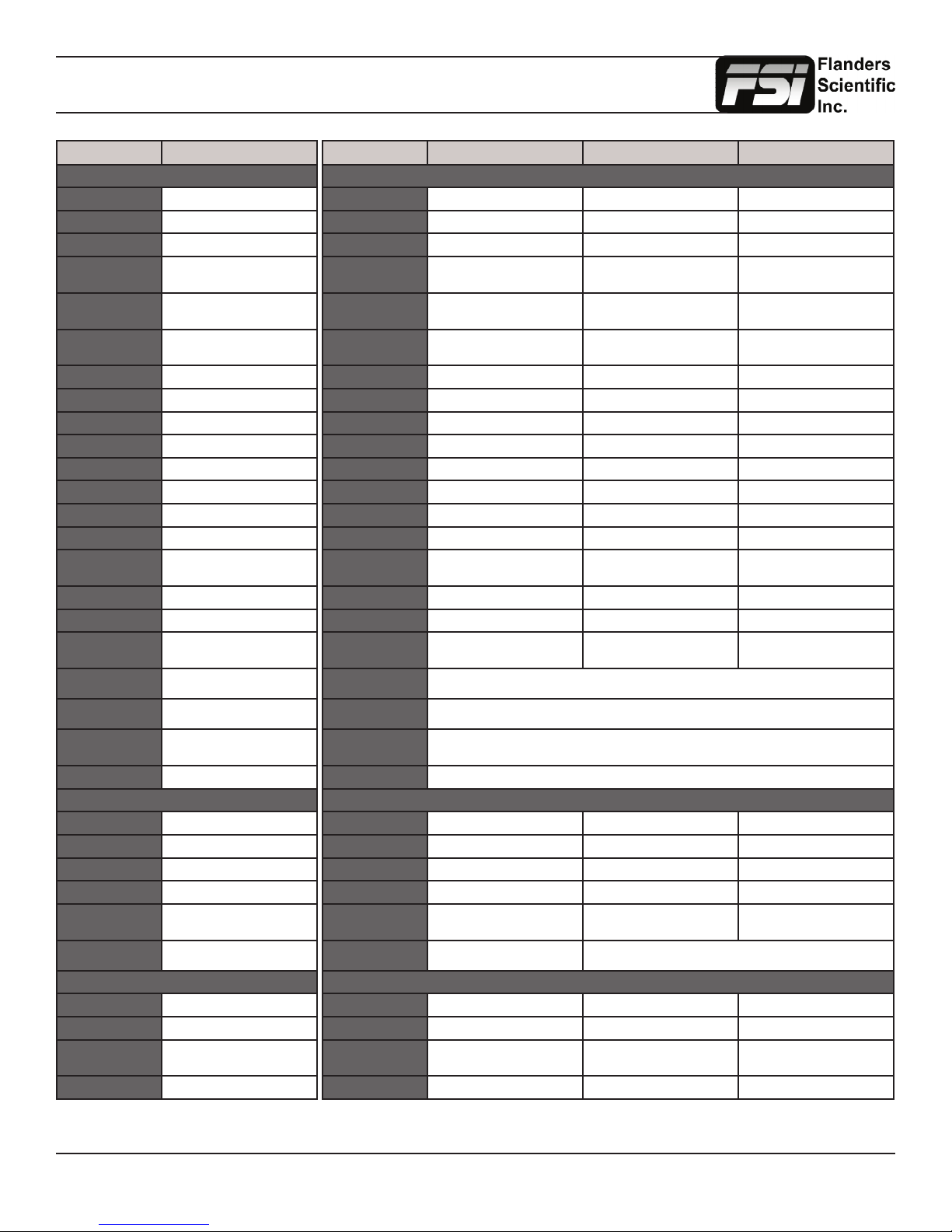
Monitor Specications
LM Series
Features
Rack Mount Kit Single or Dual
Desktop Stand N/A
External Mounting 1/4” x 20 Top & Bot
VESA to Light Stand
Mount
Carrying Bag w/
Integrated Hood
Clear Protective
Panel Cover
16 Scope Modes Yes
Measure Function Yes
H/V Delay Yes
Reverse Scan No
Timecode Display LTC, VITC1, VITC2
Color Fidelity Engine No
Overscan Yes
1:1 Pixel Mapping Ye s
Picture by Picture
Freeze Frame
Blue Only Mode Yes
Monochrome Mode Yes
3D Lut Color Space
Selection
Color Temp Select 3200K, 5000K, 5600K, 6500K,
Gamma Selection Instantly adjustable between 1.0 /
SD Aspect Ratio
Selection
Tally Lights 3 Color Front & Rear (Talent)
Power
AC Input Standard with Adaptor
DC Input Standard
Battery Plate V-Mount or Gold Mount
Power Requirement 12 VDC
DC Power Consump-
tion
Energy Saving Mode No Load Power Consumption <
Physical Characteristics
Weight (w/o stand) 3.0 lbs
Weight (with stand) N/A
Weight in Carrying
Bag with Hood
Aluminum Frame Ye s
1.8 / 2.0 / 2.2 / 2.35 / 2.4 / 2.5 / 2.8
LM-0750W
N/A
Optional
Optional (CPC 7)
Yes
N/A
9300K
4:3 or Anamorphic
15 Watts
0.75W
4.6 lbs
BM Series
Features
Rack Mount Kit Optional Optional Optional
Desktop Stand Optional Standard Standard
External Mounting 1/4” x 20 Top & Bot 100mm VESA 100mm VESA
VESA to Light Stand
Mount
Carrying Bag w/
Integrated Hood
Clear Protective
Panel Cover
16 Scope Modes Yes Yes Ye s
Measure Function Yes Yes Ye s
H/V Delay Yes Yes Ye s
Reverse Scan No No No
Timecode Display LTC, VITC1, VITC2 LTC, VITC1, VITC2 LTC, VITC1, VITC2
Color Fidelity Engine CFE2 CFE2 CFE2
Overscan Yes Ye s Ye s
1:1 Pixel Mapping Ye s Ye s Yes
Picture by Picture
Freeze Frame
Blue Only Mode Yes Ye s Ye s
Monochrome Mode Ye s Yes Ye s
3D Lut Color Space
Selection
Color Temp Select 3200K, 5000K, 5600K, 6500K, 9300K
Gamma Selection Instantly adjustable between 1.0 / 1.8 / 2.0 / 2.2 / 2.35 / 2.4 / 2.5 / 2.8
SD Aspect Ratio
Selection
Tally Lights Red / Green / Amber
Power
AC Input Standard with Adaptor IEC / C14 IEC / C14
DC Input Standard 4 PIN XLR 4 PIN XLR
Battery Plate V-Mount or Gold Mount Optional Optional
Power Requirement 12 VDC 100~240 VAC / 12 VDC 100~240 VAC / 12 VDC
DC Power Consump-
tion
Energy Saving Mode
Physical Characteristics
Weight (w/o stand) 3.35 lbs 9 lbs 10 lbs
Weight (with stand) N/A 11.2 lbs 12.5 lbs
Weight in Carrying
Bag with Hood
Aluminum Frame Ye s Yes Ye s
SMPTE C/EBU/REC709/DCI-P3
BM090 BM210 BM230
N/A Optional Optional
Optional Optional Optional
Optional (CPC UP 9) Optional (CPC UP 21) Optional (CPC UP 23)
Yes Yes Ye s
USER
23 Watts 28 Watts @ 120 cdm2
4.95 lbs 17.8 lbs N/A
SMPTE C/EBU/REC709/DCI-P3
USER
4:3 or Anamorphic
37 Watts @ 275 cdm2
SMPTE C/EBU/REC709/DCI-P3
USER
30 Watts @ 120 cdm2
40 Watts @ 275 cdm2
Return to Table of Contents
43
© 2014 Flanders Scientic, Inc.
Page 44
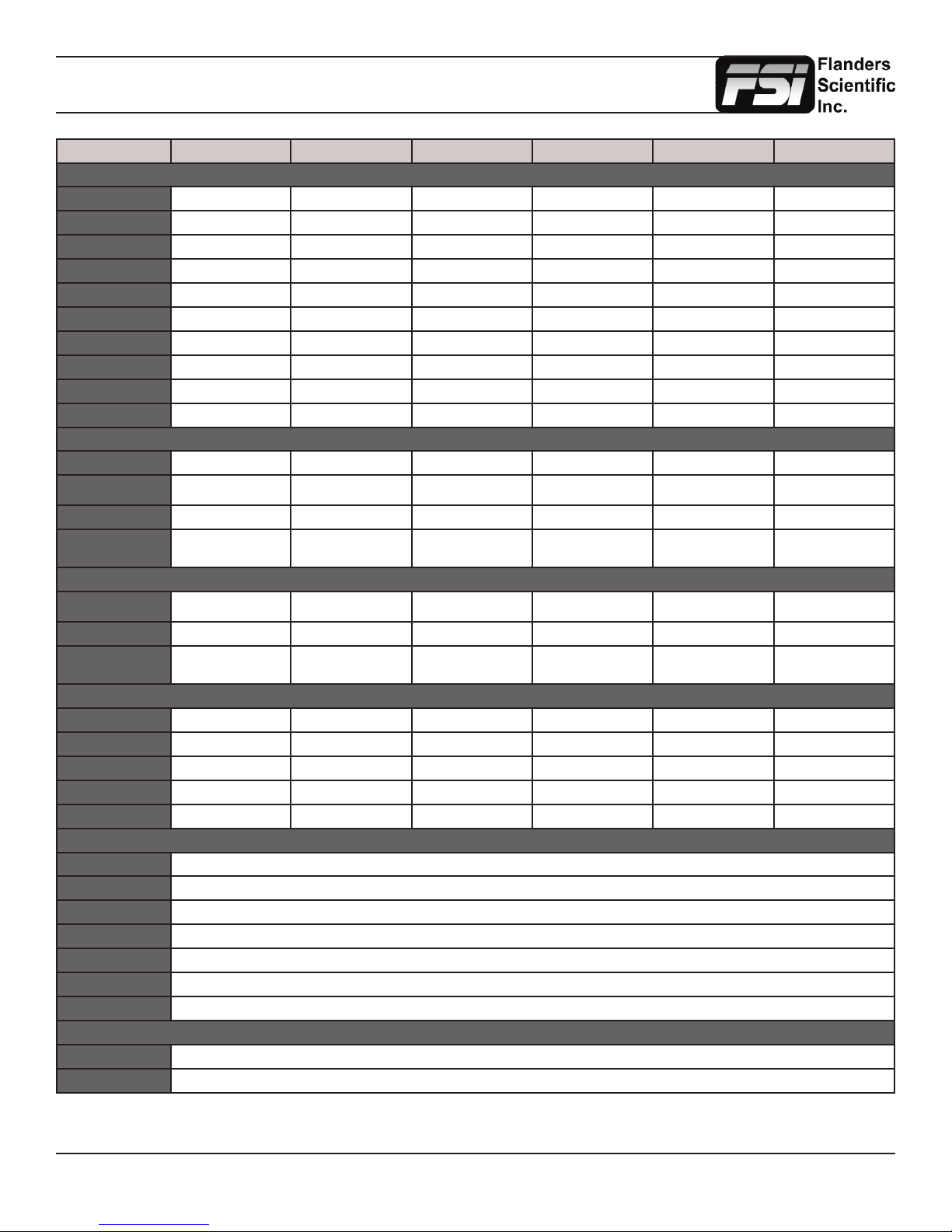
Monitor Specications
CM Series
Panel Specications
Screen Size 17.3” 16.5” 24” 24.5” 42” 50”
Resolution 1920x1080 1920x1080 1920x1200 1920x1080 1920x1080 1920x1080
Aspect Ratio 16:9 16:9 16:10 16:9 16:9 16:9
Bit Depth (Colors) True 10 bit (1.073B) 10 bit OLED (1.073B) 10 bit FRC (1.073B) 10 big OLED (1.073B) True 10 bit (1.073B) True 10 bit (1.073B)
3D Polarizing Filter No No No No Ye s Ye s
Processing 12 Bit 12 Bit 12 Bit 12 Bit 12 Bit 12 Bit
Contrast Ratio 1000:1 ≥ 5000:1 1100:1 ≥ 5000:1 1600:1 1600:1
Backlight RGB LED N/A OLED CCFL N/A OLED White LED White LED
Max Luminance 250nit TBA 350nit TBA 250nit 250nit
Viewing Angle 178° 179° 178° 179° 178° 178°
Inputs
1x DVI-I DVI-I (Analog/Digital) DVI-I (Analog/Digital) DVI-I (Analog/Digital) DVI-I (Analog/Digital) DVI-I (Analog/Digital) DVI-I (Analog/Digital)
2x BNC 3Gbps/Dual Link/HD/
1x BNC Composite Composite Composite Composite Composite Composite
3x BNC Component
Outputs
2x BNC 3Gbps/Dual Link/HD/
1x BNC Composite Composite Composite Composite Composite Composite
3x BNC Component
CM171 CM172 CM240 CM250 CM420TD CM500TD
SD-SDI
(YPbPr/RGB)
SD-SDI
(YPbPr/RGB)
3Gbps/Dual Link/HD/
SD-SDI
Component
(YPbPr/RGB)
3Gbps/Dual Link/HD/
SD-SDI
Component
(YPbPr/RGB)
3Gbps/Dual Link/HD/
SD-SDI
Component
(YPbPr/RGB)
3Gbps/Dual Link/HD/
SD-SDI
Component
(YPbPr/RGB)
3Gbps/Dual Link/HD/
SD-SDI
Component
(YPbPr/RGB)
3Gbps/Dual Link/HD/
SD-SDI
Component
(YPbPr/RGB)
3Gbps/Dual Link/HD/
SD-SDI
Component
(YPbPr/RGB)
3Gbps/Dual Link/HD/
SD-SDI
Component
(YPbPr/RGB)
3Gbps/Dual Link/HD/
Component
(YPbPr/RGB)
3Gbps/Dual Link/HD/
Component
(YPbPr/RGB)
SD-SDI
SD-SDI
Audio
Audio Disembedding Ye s Ye s Yes Yes Yes Yes
Audio Level Meters Yes Yes Yes Yes Yes Yes
Internal Speakers 2 2 2 2 2 2
Audio In 1 Mini-Phono 1 Mini-Phono 1 Mini-Phono 1 Mini-Phono 1 Mini-Phono 1 Mini-Phono
Audio Out 1 Mini-Phono 1 Mini-Phono 1 Mini-Phono 1 Mini-Phono 1 Mini-Phono 1 Mini-Phono
Supported SDI Formats
ITU-R BT.656 (PAL) 576i (50)
SMPTE-125M 480i (59.94)
SMPTE-274M 1080i (60/59.94/50) 1080p (30/29.97/25/24/24PsF/23.98/23.98PsF)
SMPTE-296M 720p (60/59.94/50/30/29/25/24/23.98)
2K 2048x1080 (23.98PsF/24PsF/23.98p/24p)
SMPTE-372M 1080i (29.97/25/24/23.98) 1080p (30/29.97/25/24/23.98) 720p (60/59.94/50) 4:4:4 YCbCr, RGB
SMPTE-425M Standard (Level A & B)
Supported DVI Formats
DVI-A & DVI-D VGA (640x480), NTSC (720x480), SVGA (800x600), XGA (1024x768), SXGA (1280x1024)
DVI Digital Only 1280x720, 1440x900, 1920x1080, 1920x1200
Return to Table of Contents
44
© 2014 Flanders Scientic, Inc.
Page 45
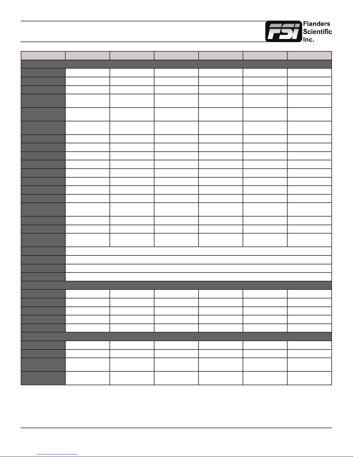
Monitor Specications
Model CM171 CM172 CM240 CM250 CM420TD CM500TD
Features
Rack Mount Kit Included Included Optional Optional N/A N/A
Desktop Stand Standard Standard Standard Standard Standard Standard
External Mounting 100mm VESA 100mm VESA 100mm VESA 100mm VESA 400mm VESA 400mm VESA
VESA to Light Stand
Mount
Carrying Bag w/ Integrated Hood
Clear Protective Panel
Cover
16 Scope Modes Yes Ye s Yes Ye s Yes Ye s
Measure Function Ye s Yes Ye s Ye s Yes Ye s
H/V Delay Ye s Ye s Ye s Yes Ye s Ye s
Reverse Scan No No No No No No
Timecode Display LTC, VITC1, VITC2 LTC, VITC1, VITC2 LTC, VITC1, VITC2 LTC, VITC1, VITC2 LTC, VITC1, VITC2 LTC, VITC1, VITC2
Color Fidelity Engine CFE CFE2 CFE2 CFE2 CFE2 CFE2
Overscan Yes Yes Yes Yes Ye s Ye s
1:1 Pixel Mapping Yes Ye s Yes Ye s Yes Ye s
Picture by Picture Freeze
Frame
Blue Only Mode Ye s Ye s Ye s Ye s Ye s Yes
Monochrome Mode Ye s Yes Ye s Ye s Ye s Yes
3D Lut Color Space
Selection
Color Temperature Select 3200K, 5000K, 5600K, 6500K, 9300K
Gamma Selection Instantly adjustable between 1.0 / 1.8 / 2.0 / 2.2 / 2.35 / 2.4 / 2.5 / 2.8
SD Aspect Ratio 4:3 or Anamorphic
Tally Lights Red / Green / Amber
Power
AC Input IEC / C14 IEC / C14 IEC / C14 IEC / C14 IEC / C14 IEC / C14
DC Input 4 PIN XLR 4 PIN XLR 4 PIN XLR 4 PIN XLR 4 PIN XLR 4 PIN XLR
Battery Plate Optional Optional Optional 12V Conversion Optional 12V Conversion N/A N/A
Power Requirement 100~240 VAC / 12 VDC 100~240 VAC / 12 VDC 100~240 VAC / 24 VDC 100~240 VAC / 24 VDC 100~240 VAC / 24 VDC 100~240 VAC / 24 VDC
DC Power Consumption 28 Watts 42 Watts 50 Watts 50 Watts 46 Watts 53 Watts
Physical Characteristics
Weight (w/o stand) 6.4 lbs (2.9kg) 11.3 lbs (5.1kg) 15.8 lbs (7.1kg) 17 lbs (7.7kg) 34.6 lbs (15.7kg) 46.2 lbs (20.9kg)
Weight (with stand) 10.4 lbs (4.7kg) 13.5 lbs (6.1kg) 19.8 lbs (8.9kg) 19.2 lbs (8.7kg) N/A N/A
Weight in Carrying Bag
with Hood
Die Cast Aluminum
Frame
Optional Optional Optional Optional Optional N/A
Optional Optional N/A N/A N/A N/A
Optional Optional Optional Optional N/A N/A
Yes Ye s Yes Ye s Yes Ye s
SMPTE C/EBU/REC709/
DCI-P3/USER
14.5 lbs (6.6kg) 19.4 lbs (8.7kg) N/A N/A N/A N/A
Yes Ye s Yes Ye s Yes Ye s
SMPTE C/EBU/REC709/
DCI-P3/USER
SMPTE C/EBU/REC709/
DCI-P3/USER
SMPTE C/EBU/REC709/
DCI-P3/USER
SMPTE C/EBU/REC709/
DCI-P3/USER
SMPTE C/EBU/REC709/
DCI-P3/USER
Return to Table of Contents
45
© 2014 Flanders Scientic, Inc.
 Loading...