

FSI BM090, BM210, CM172, CM240, CM250 User Manual
...
Monitor User Manual
Updated 12.18.2014
BM Series CM Series
BM090 CM171
BM210 CM172
BM230 CM240
CM250
CM420TD
CM500TD
This manual is based on rmware version 1.0.00-1969. If you
have an older or newer rmware version some of the functions
mentioned in this manual may not be present or may operate
differently.
E-Mail: Support@FlandersScientic.com
Flanders Scientic, Inc.
6215 Shiloh Crossing
Suite G
Alpharetta, GA. 30005
Phone: +1.678.835.4934
Fax: +1.678.804.1882
www.FlandersScientic.com

Contents
TOPIC PAGE(S)
Safety Precautions 3-4
Parts & Their Functions 5-6
Menu Navigation / System Status 7
Function Menu 8-17
Marker Menu 18
Video Menu 19-20
Scopes & VU Meters Menu 21-23
System Menu 24-26
Alarm Menu 27-29
OSD Menu 30
GPI Menu 31
Audio Menu 32
Color Management Menu 33
Color Management Menu: DIT LUTs 34-35
Color Management Menu:
Custom Calibration LUTs 36-39
Troubleshooting Guide 40-41
Monitor Specications 42-45
Return to Table of Contents
2
© 2014 Flanders Scientic, Inc.

Safety Precautions
• All operating instructions must be read and understood before the product is operated.
• These safety and operating instructions must be kept in a safe place for future reference.
• All warnings on the product and in the instructions must be observed closely.
• All operating instructions must be followed.
• Do not use attachments or accessories not recommended by the manufacturer. Use of inadequate attachments may
result in serious accidents.
• Do not place heavy objects on the power cord. Route power cord to prevent people from stepping on or resting objects
on the cord. Check to ensure that both outlet and product connection points are properly seated and secured.
• This product must be operated on a power source as specied on the specication label or product screening. Always
operate the product within the voltage range specied.
• Do not overload AC outlets or extension cords. Overloading can cause re or serious electric shock.
• Never insert an object into the product through vents or openings as this can cause serious electric shock or damage.
• Do not expose product to water or other liquids as this can lead to electrical shock or permanent damage.
• Do not attempt to service the product yourself. Removing covers can expose you to high voltage and other unsafe
conditions. Please seek the assistance of a qualied service professional for all service needs.
• If any of the following occur, unplug the power cord from the AC outlet and consult a qualied service professional to
perform repairs:
• Power cord or plug becomes damaged.
• When any liquid is spilled on or in the product.
• When the product has been exposed to rain or water.
• When the product does not operate properly as described in the instruction manual.
• When the product has been dropped or damaged.
• If the product requires replacement parts, make sure that the service person uses replacement parts specied by the
manufacturer, or those equivalent parts having the same characteristics and performance specications as the original
parts. Use of unauthorized parts can result in re, electric shock, and/or other damage.
• Upon completion of any service or repair work, request that the service technician perform safety checks to ensure that
the product is in proper working order.
• When mounting the product to a wall, ceiling, or within a rack/enclosure, be sure to install the product according to the
instructions of both the mount and monitor manufacturer.
• Unplug the power cord from the AC outlet before cleaning the product.
• For proper screen maintenance please follow the guidelines below to prevent scratches, discoloration, or other damage
to the panel:
• Avoid striking the screen with any object.
• Do not wipe screen hard. Apply only gentle pressure if cleaning.
• Do not wipe the screen with solvents such as alcohol, paint thinner, or benzene as this can cause permanent
damage to the panel.
• Do not spray detergent or other cleaners directly on the monitor or panel.
• Do not write on the panel with any substance or object.
• Do not paste or stick anything to the screen as any adhesive can cause damage to the panel.
• Screen may be cleaned by gently wiping with lint free cloth to remove dust. For more thorough cleaning use a
lint free cloth that has been very lightly dampened with distilled water. Please dry any excess moisture from the
monitor or panel immediately to prevent damage.
Return to Table of Contents
3
© 2014 Flanders Scientic, Inc.

Safety Precautions
• For proper chassis maintenance please follow the guidelines below to avoid any potential damage:
• Do not wipe the chassis with solvents such as alcohol, paint thinner, or benzene.
• Do not expose the cabinet to any volatile substances.
• Do not allow prolonged contact with rubber or plastic.
• Apply only gentle pressure to chassis when cleaning.
• To clean use soft, lint free cloth to remove dust. A lightly dampened cloth, as described in the screen maintenance
section, may also be used to clean the chassis.
• Take care in moving this product as serious injury or death can result from the sudden shifting or falling of this object.
• The vents and openings in the product’s chassis are designed for ventilation. Do not cover, block, or otherwise obstruct
these vents and openings as insufcient ventilation can cause overheating and/or shorten the life of the product. Do not
place the object on a bed, sofa, rug, or other similar surface as this can result in serious obstruction of ventilation areas.
If using in enclosed space make sure to provide proper ventilation to maintain allowable operating temperature range.
• The panel used in this product contains glass and can cause serious injury if broken. If the unit is dropped or otherwise
damaged take care to avoid possible injury by glass shards.
• Keep this product away from heat generating sources such as radiators, heaters, stoves, or other heat generating
products.
• Avoid prolonged exposure to direct sunlight as this can cause damage to the panel
FCC (Federal Communications Commission)
This equipment has been tested and found to comply with the limits for a class A digital device, pursuant to part 15
of the FCC Rules. These limits are designed to provide reasonable protection against harmful interface when the
equipment is operated in a commercial environment.
This equipment generates, uses, and can radiate radio frequency energy, and if not installed and used in accordance
with the instruction manual, may cause harmful interference to radio communications.
Warning: Changes or modications not expressly approved by the manufacturer responsible for compliance void
the user’s authority to operate the equipment.
Return to Table of Contents
4
© 2014 Flanders Scientic, Inc.
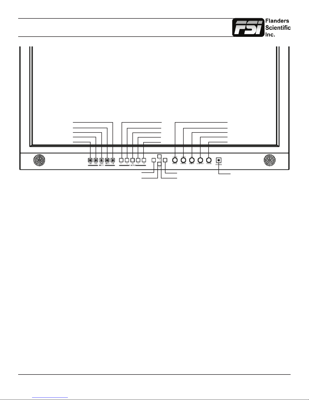
Parts & Their Functions
DVI
VIDEO
YPbPr
SDI 2
SDI 1
MENU
DOWN
F1
F2
F3
F4
F5
ENTER
UP
PHASE / H POS
CHROMA / V POS
BRIGHT / Ref POS
CONTRAST / F Stop
VOLUME / Reset
POWER
• SDI 1: Used to select SDI Input 1 as the active Input.
• SDI 2: Used to select SDI Input 2 as the active Input.
• YPbPr: Used to select the Component Analog Input as the active Input.
• VIDEO: Used to select the Composite Analog Input as the active Input.
• DVI: Used to select the DVI-I Input as the active Input. DVI-Digital / DVI-Analog toggle is available in the System Menu
(Menu/System/DVI Selection).
• F1: Assignable function key. This key’s function is selectable from the Function Menu.
• F2: Assignable function key. This key’s function is selectable from the Function Menu.
• F3: Assignable function key. This key’s function is selectable from the Function Menu.
• F4: Assignable function key. This key’s function is selectable from the Function Menu.
• F5: Assignable function key. This key’s function is selectable from the Function Menu.
• MENU: Used to enable On Screen Menu.
• UP: Used in combination with DOWN and ENTER Keys to navigate On Screen Menu.
• DOWN: Used in combination with UP and ENTER Keys to navigate On Screen Menu.
• ENTER: Used in combination with UP and DOWN Keys to navigate On Screen Menu. The ENTER button is used to
conrm selections within the On Screen Menu.
• POWER: Used to turn power on/off.
• VOLUME: Used to adjust volume. Press down on this knob to instantly mute or unmute the volume.
• CONTRAST: Used to adjust contrast higher or lower. Pressing down on the center of this button will return the contrast
setting to its default position.
• BRIGHT / F.D. / Ref POS: Used to adjust brightness higher or lower. Pressing down on the center of this button will
return the brightness setting to its default position. The brightness knob should NOT be used increase the overall peak
white luminance of the unit, use the Luminance setting on the System Menu to adjust overall luminance.
• CHROMA / V POS: Used to adjust chroma higher or lower. Pressing down on the center of this button will return the
chroma setting to its default position.
• PHASE / H POS: Used to adjust phase. Pressing down on the center of this button will return the setting to default. Hue
is locked by default on SDI, but can be unlocked by the SDI Hue Adjustment option on the System Menu.
• Tally: Three color tally lamp controlled via remote control.
Return to Table of Contents
5
© 2014 Flanders Scientic, Inc.
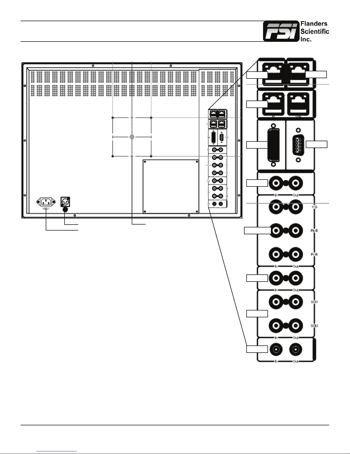
Parts & Their Functions
DC Power
AC Power
100mm VESA
LAN
RJ-485
DVI-I
Video
Component
GPI
RS-232
• LAN: IP Control via select programs. This feature is in beta.
• GPI: General Purpose Interface for Contact Closure Remote Control.
Remote Control Functions can be assigned from the GPI Menu.
• RS-485: RS-485 Ports (In/Out) for looping remote control interface.
• DVI-I: DVI-I Input. Supports both DVI-Analog & DVI-Digital.
Analog / Digital Toggle is found on System Menu.
• Video In/Out: Composite Video Input & Loop Through.
• Component In/Out: Component Video (SD & HD autosensing) Input & Loop
Through.
Supports both YPbPr & RGB signals.
• Ext. Sync. In/Out: External Reference Synchronization Interface.
• SDI In 1 & SDI In 2: Two Autosensing, Autoswitching, Multi-Format 3G/Dual-Link/
HD/SD-SDI Inputs.
• SDI Out 1 & Out 2: Two looped 3G/Dual-Link/HD/SD-SDI Outputs.
• Audio In/Out: Analog Stereo Mini-phono Audio Input & Output. Unbalanced, Audio
Out delayed by exact amount of monitor video procesisng time to maintain sync.
Ext Sync
SDI
Audio
Return to Table of Contents
6
© 2014 Flanders Scientic, Inc.

Menu Navigation / System Status
Main Menu
Pressing the MENU button on the monitor’s keypad will call up the On Screen Menu, as shown below:
Main Menu Function
Function F1 Scopes & Audio Meters 1
Scopes & Audio Meters F2 Scopes & Audio Meters 2
Video F3 Scopes & Audio Meters 3
Audio F4 Marker 1
Marker F5 Measurement (10Bit)
System Function Display On
Alarm
OSD
GPI
Color Management
System Status
Support
Navigating the Main Menu
To navigate the Main Menu simply use the UP and DOWN keys to highlight a category and press the ENTER button to
select the highlighted sub menu. Navigate the sub menu in the same way by using the UP and DOWN keys to highlight a
particular function and press ENTER to toggle between that function’s settings. To exit the menu or back out of a sub menu
simply press the MENU button.
System Status Category
The System Status category does not contain any congurable settings, but does provide important information regarding
your monitor’s serial number, rmware version, & current conguration.
Main Menu System Status
Function Input DVI-D
Scopes & Audio Meters Input Mode 1080p 60hz
Video Overscan Off
Audio Pixel Mapping Off
Marker Volume 16
System Contrast 0
Alarm Brightness 0
OSD Chroma 0
GPI Hue 0
Color Management Model BM210
System Status Version 1.0.00-1969
Support S/N M210A0000
Note that pressing an input button will temporarily call up a secondary system status summary window that will indicate
incoming signal resolution and frame rate, active color space selected on Color Management menu, gamma response
selected on Video Menu, & color matching function selected on Color Management Menu*.
*Color Matching Function toggle only works on OLED units, all other units currently use CIE 1931 CMF only.
Return to Table of Contents
7
© 2014 Flanders Scientic, Inc.
Function Menu
Main Menu Function
Function F1 Scopes & Audio Meters 1
Scopes & Audio Meters F2 Scopes & Audio Meters 2
Video F3 Scopes & Audio Meters 3
Audio F4 Marker
Marker F5 Measurement (10Bit)
System Function Display On
Alarm
OSD
GPI
Color Management
System Status
Support
The Function Menu allows you to assign user selectable functions to any of the 5 function buttons (F1, F2, F3, F4, & F5)
on the monitor keypad. Many monitor features listed as assignable options in the function menu are also selectable via the
embedded menus and are present simply to provide an option for faster, single button press access to the desired function.
Other features listed require a function key for activation, but may have associated customizable settings that can be found
in other menus.
Assigning Function Keys
To assign a function to a function key highlight one of the 5 Function lines and press ENTER. A list of assignable functions
will appear. Select the desired function with the UP and DOWN buttons and press ENTER to assign that function to the
corresponding function key. The Function Display option at the bottom of the Function Menu gives you the option to have
a temporary conrmation window appear on screen after a function key is pressed that will identify the function that was
turned on or off.
WARNING: Changing a function button
assignment does NOT automatically
turn an active function off. Make sure to
disable unwanted active functions before
changing function button assignments.
NOTE: Many features (Waveform,
Vector Scope, Audio Level
Meters, etc.) require a function
key in order to operate. Some
menus (such as the Scopes &
Audio Meters Menu) only set
your display preferences while a
corresponding function key must
be assigned to turn the feature
on and off. If you are having
trouble with a monitor feature
make sure you have assigned
the proper function key and any
corresponding menu settings.
Scopes & Audio Meters 1, 2, 3
These functions toggle on/off a Scopes & Audio Meters prole. Three prole slots are available from the Scopes & Audio
Meters Menu and each prole can be set to a specic function key allowing you to instantly toggle between various types of
Scope and/or Audio Level Meter congurations. Please note that if you have set both Scopes Windows to the Off position in
the Scopes & Audio Meters menu nothing will appear on screen when you toggle this function (see Scopes & Audio Meters
Menu section of this manual for more details).
Cross Hatch
The Cross Hatch function toggles on/off the onscreen display of a graphical cross hatch overlay.
Marker 1, 2, 3
These functions activate the onscreen display of the preset Area, Safety, Custom Graticules, or Active Boundary Markers as
set in the Marker Proles. Marker Proles can be customized via the Marker Menu. By utilizing this function you can toggle
on/off your selected markers with a single function key (see Marker Menu section of this manual for more details).
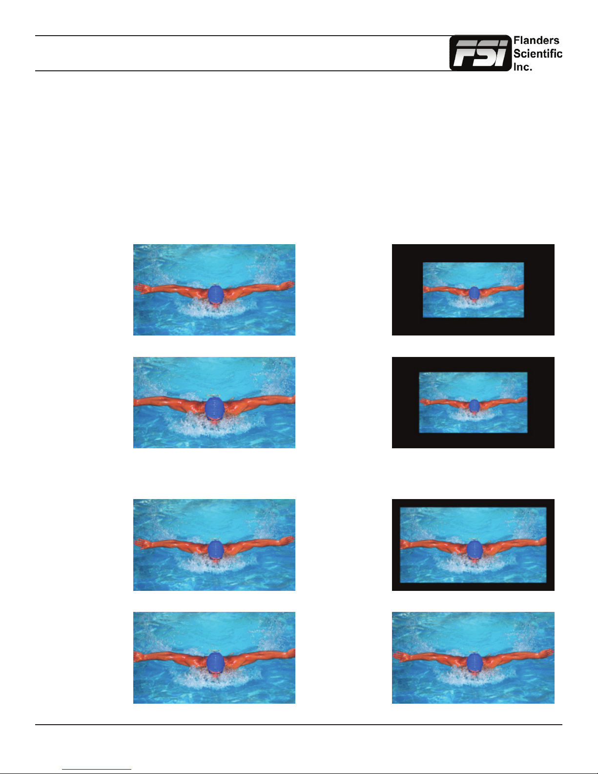
Overscan
The Overscan function can work with 1:1 Pixel mapping mode on or off. With 1:1 Pixel to Pixel mapping mode turned off
the Overscanned image is scaled full screen. With 1:1 Pixel to Pixel mapping mode turned on the image remains unscaled,
but the area lying outside of the active scan area is blacked out. This area represents the same area not visible with Pixel
to Pixel mode off.
Return to Table of Contents
8
© 2014 Flanders Scientic, Inc.
Function Menu
Details on Overscan Function
With the overscan function off all active lines of video can be displayed on screen. With overscan on a small percentage
of the outermost active video will not be displayed. Additionally, the monitor can scale the overscanned video full screen
or ‘blackout’ the outlying area while maintaining a pixel to pixel display of the video inside the active scan area. To toggle
between these variations of Overscan use the 1:1 Pixel to Pixel mapping function. With both Pixel to Pixel mapping and
Overscan selected the area outside of the active scan will simply be blacked out, but the active video will not be scaled
outside of the 1:1 pixel scan. With Pixel to Pixel mapping off and overscan on the active scan area will be scaled full screen.
To view all active lines in Pixel to Pixel mapping mode make sure to turn Overscan off.
Overscan Examples
(Images represent 720p source on BM230)
Pixel to Pixel Off
Overscan Off
Pixel to Pixel Off
Overscan On
More Overscan Examples
(Images represent 1080i source on BM230)
Pixel to Pixel Off
Overscan Off
Pixel to Pixel On
Overscan On
Pixel to Pixel On
Overscan Off
Pixel to Pixel On
Overscan On
Pixel to Pixel Off
Overscan On
Return to Table of Contents
Pixel to Pixel On
Overscan Off
9
© 2014 Flanders Scientic, Inc.

Function Menu
Sub Window
Largely deprecated for use on CFE2 equipped units. For side by side viewing on CFE2 units please use the dedicated PIP
function instead. The Sub Window function enables a Picture by Picture mode. After assigning the Sub Window function
to a function key the rst key press will result in a picture by picture display of your active input. Once sub window mode is
active you can press down on the H POS rotary knob to freeze the image on the right while the image on the left will continue
to show your live source. Once frozen you can also switch to any other input provided that the resolution of that input is the
same as the frozen source. To exit sub window simply press the assigned function key again.
Pixel Mapping
The Pixel Mapping function toggles between various available pixel mapping options. Options vary depending on the
incoming source, but may include the following:
1:1 Pixel Mapping: 1 pixel of incoming source is displayed as 1 pixel onscreen. If the incoming source resolution is less
than the total pixel count of the monitor your source will not ll the screen. This is often referred to as a postage stamp
representation of the source. If the incoming source resolution is greater than the total pixel count of the monitor then only
a portion of the incoming source will be shown onscreen, but the pixel position function (controlled by the H POS rotary
knob) may be used to view different sections of the 1:1 pixel representation. The monitor’s tally light will ash to remind
you that you are in 1:1 pixel mapping mode if any portion of the image is not shown on screen when in 1:1. This pixel
mapping mode can be combined with the SD Aspect Function (Anamorphic toggle) to activate a PAL SD FHA viewing
mode on the monitor. Once pixel mapping is active pressing down on the H POS knob will move the source to a different
onscreen position when pressed. Please note that if the incoming source is the same resolution as the panel the image
will not move. On monitors with lower than 1920x1080 resolution this feature can be used to view any section of a 1080
source in a native 1:1, unscaled format. Similarly, on all native 1920x1080 or 1920x1200 resolution monitors this mode
will allow you to view any portion of an incoming 2K source in an unscaled 1:1 onscreen representation.
2:1 Pixel Mapping (SD sources only): Every individual pixel of the incoming source is represented by four pixels onscreen.
This scaling algorithm is simple and allows for a largely artifact free double size version of the 1:1 Pixel Mapping Mode for
SD sources. While 2:1 scaling will still not ll the entire screen on a 1920x1080 resolution monitor, it does use a majority
of the vertical screen height and provides an excellent quality large scale representation of the SD source.
Full Screen Mapping: The full screen mode will scale the incoming source to ll as much of the screen as
possible while preserving the incoming source’s native aspect ratio. If the incoming source and panel share
the same resolution then there will be no difference between 1:1 pixel mapping and full screen pixel mapping.
Please note that the Overscan function will be represented differently based on the pixel mapping selection that you select.
Pixel Position
This feature is a part of the Pixel Mapping function and provides a toggle for positioning a 1:1 Pixel to Pixel mapped
representation of an incoming source on different areas of the screen. Once pixel mapping is active the H POS knob
will move the source to a different onscreen position when pressed. Please note that if the incoming source is the same
resolution as the LCD panel the image will not move. The pixel position feature does not work unless the 1:1 Pixel to Pixel
mapping mode function is turned On. On 7”, 9”, and 17” monitors this feature can be used with the Pixel to Pixel Mode
to view any section of a 1080 source in a native 1:1, unscaled format. Similarly, on all native 1920x1080 or 1920x1200
resolution monitors this mode will allow you to view any portion of an incoming 2K source in an unscaled 1:1 onscreen
representation.
H/V Delay Mode
This mode activates the Horizontal and Vertical Delay function to highlight the horizontal and vertical blanking portions of
the incoming signal.
Mono Mode
This mode activates the Monochrome function. Press once to turn on and again to turn off.
Return to Table of Contents
10
© 2014 Flanders Scientic, Inc.
Function Menu
SD Aspect Ratio
Toggles between 4:3 and Anamorphic display of Standard Denition source. This function should be set to match the SD
source being viewed. The default setting is 4:3. If used in conjunction with 1:1 pixel mapping this function can also activate
a PAL SD FHA viewing mode.
Full Screen
This function simply stretches any incoming source to ll the entire screen. Unlike the Zoom feature this full screen stretch
does not preserve aspect ratio, but it does keep all of the active video signal present. Though the full screen mode has
many potential uses it was designed primarily for use with rasterizers that generate a 16:10 or 16:9 aspect 1024x768 output.
Enabling Full Screen mode allows the monitor to stretch the image as intended by the rasterizer.
Pixel Zoom
The Pixel Zoom function will generate a positionable and resizable rectangle on screen. The rectangle may be moved left or
right using the H POS rotary knob and up or down using the V POS rotary knob. The Ref POS rotary knob may be used to
change the size of the onscreen rectangle. Using these three rotary knobs you can select any area on screen and then press
down on the F Stop rotary knob to zoom to the selected area. This pixel zoom feature is designed to work with any HD signal
formats. A ashing tally light will be activated on your monitor whenever you are in a zoomed mode as a reminder/warning
that the entire incoming signal is not being shown on the monitor. To exit the zoomed mode simply press down on the F
Stop rotary knob once more. To exit the Pixel Zoom feature entirely simply press the function button assigned to this feature
once more. The Pixel Zoom function allows for an essentially artifact free, high quality zoom on any portion of an HD signal.
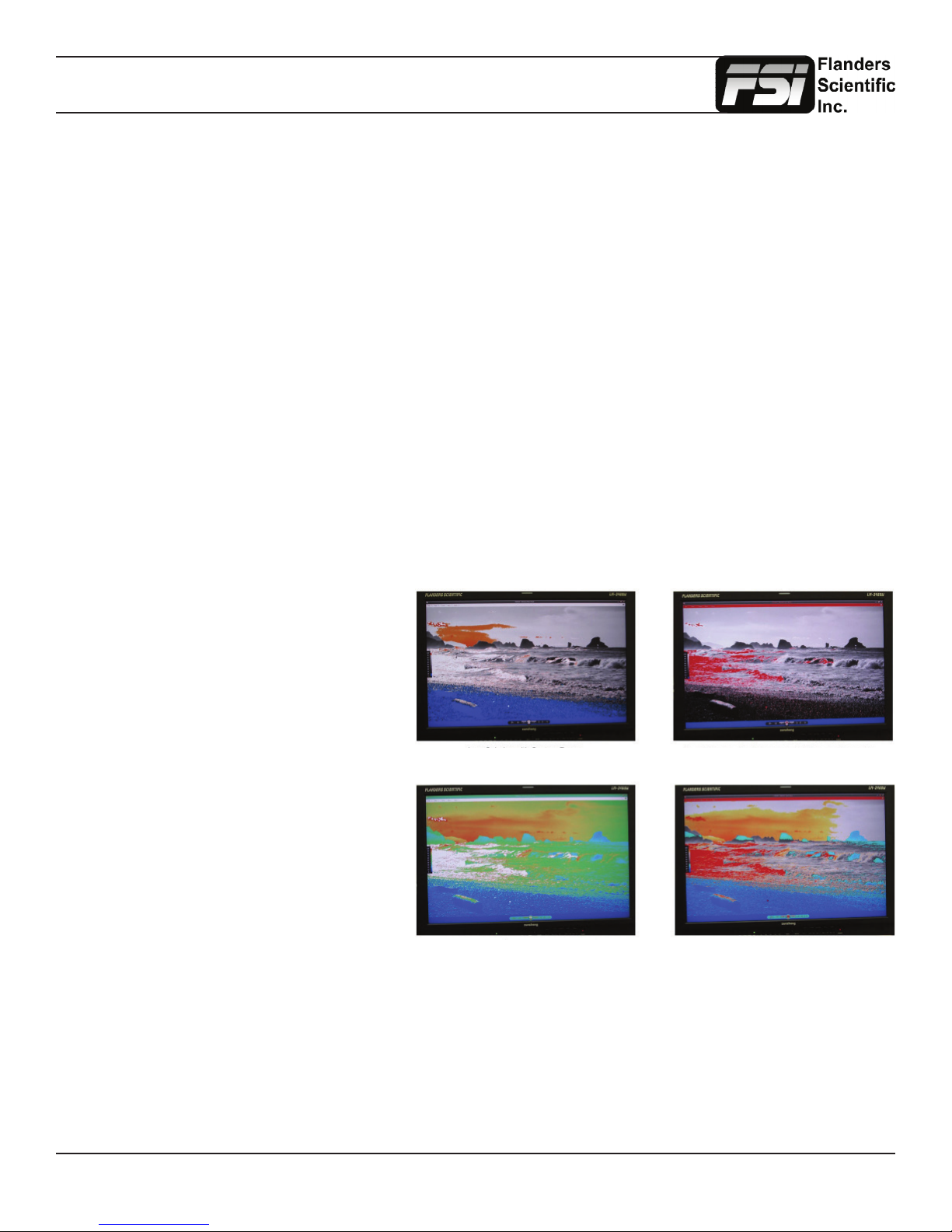
LUM Coloring
This function generates an articial luminance
map of the incoming source that can be
particularly useful in identifying overexposed
areas in any given shot. An onscreen scale
helps indicate what articial color corresponds
to what luminance level. The scale will follow
the selected Waveform Scale set in the Scopes
& VU Meters Prole 1: you can choose from
IRE, Digital Levels, or Voltage. In its default
conguration the LUM Coloring feature will
highlight all levels above 100IRE as white and
all levels below 0 IRE as black. In default mode
levels between 0 and 100 IRE will be color
coded. However, you can change the range of
these color coded regions to any preferred
setting by using the monitor’s rotary knobs.
The H POS rotary knob will adjust the lower
limit of the lower color coded region. The
V POS rotary knob will adjust the upper limit
of the lower color coded region. The Ref
POS rotary knob will adjust the lower
LUM Coloring with Custom Range LUM Coloring with All Legal Levels Shown in Greyscale
LUM Coloring in Default Mode
Overexposed Areas in White
Underexposed Areas in Black
Underexposed Areas in Blue
Overexposed Areas in Red
LUM Coloring with Custom Range
limit of the upper color coded region.
The F Stop Rotary knob will adjust the upper limit of the upper color coded region. These color coded ranges are retained in
memory so you can exit and reenter LUM Coloring Mode without having to reset your desired threshold levels.
Blue/Red/Green Only
This function activates the monitor’s Blue Only, Red Only, and Green Only modes. The respective channels can be shown
as just that color (Red, Green, Blue) or as monochrome.
Return to Table of Contents
11
© 2014 Flanders Scientic, Inc.

Function Menu
Measurement (10bit & 8bit)
This function allows you to get precise real time YRGB measurements of any point or area within your incoming signal.
With the Measurement function on you can use the H POS and V POS rotary knobs to position your crosshair over the point
within your source that you would like to measure. To reset the vertical or horizontal position of your crosshair back to center
simply press down on the corresponding rotary knob. You may also use the Ref POS rotary knob to select the size of the
sampling area for the measurement data (from a single pixel to a much larger area where the values will be an average of
all pixels within your dened sample area). As you move the crosshair your Measurement data will update in real time. The
Measurement function is available in a 10 bit mode or 8 bit mode and will provide you with the following data in real time:
• Line and Sample (Identies position of your crosshair)
• Y (Luminance as an absolute value between 0-255 for 8 bit and 0-1023 for 10 bit)
• Y% (Luminance level expressed as percentage)
• R% (Red level expressed as percentage)
• G% (Green level expressed as percentage)
• B% (Blue level expressed as percentage)
• R (Red level as an absolute value between 0-255 for 8 bit and 0-1023 for 10 bit)
• G (Green level as an absolute value between 0-255 for 8 bit and 0-1023 for 10 bit)
• B (Blue level as an absolute value between 0-255 for 8 bit and 0-1023 for 10 bit)
You can also press the Ref POS rotary knob to set a reference position onscreen. Once your reference position is set
it will be indicated on screen by a separate crosshair and you will be able to move the active crosshair to obtain a real
time readout of your current and reference positions as well as a separate readout of the precise difference between
current and reference locations. Please note that your reference position is both a spatial and temporal reference meaning
that the values indicated on screen for the reference are for that point on screen at the moment you set the reference.
Pressing the F Stop rotary knob button allows you to set your current crosshair position as an F-Stop Reference
and view differences between this current position and your reference position as an F-Stop value. The F-Stop
reference feature is independent of the Ref POS feature. The F-Stop reference value will always be based on
the levels of your current active crosshair position at the precise moment when the F-Stop knob is pressed.
The crosshair color will follow the color selected for markers from the Marker Menu. To change the color of the Measurement
function’s crosshair change the Marker color.
Measure Line Sample Y1024 R1024 G1024 B1024 Y% R% G% B% F/stop
Current 293 944 249 246 251 217 21.1 20.8 21.3 17.5 -0.0
Ref_Pos 316 994 240 240 241 219 20.1 20.1 20.2 17.7 -0.1
Diff -24 -51 9 6 10 -2 1.0 0.7 1.1 -0.2 0.1
Return to Table of Contents
12
© 2014 Flanders Scientic, Inc.
Function Menu
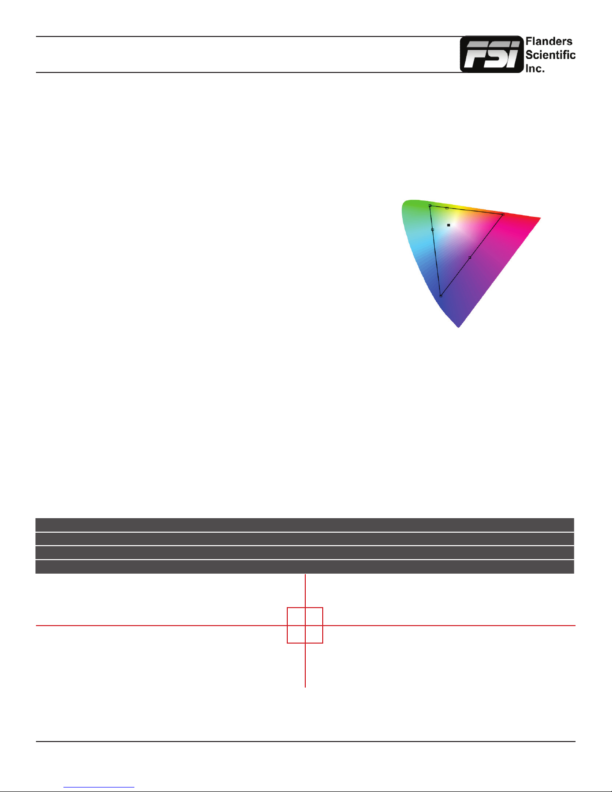
CIE Measurement
This function allows you to get precise real time chromaticty measurements of any point or area within your incoming
signal as well as a real time plot of the mesured position on a CIE color space diagram. With the Measurement
function on you can use the H POS and V POS rotary knobs to position your crosshair over the point within your
source that you would like to measure. To reset the vertical or horizontal position of your crosshair back to center
simply press down on the corresponding rotary knob. You may also use the Ref POS rotary knob to select the
size of the sampling area for the measurement data (from a single pixel to a much larger area where the values will
be an average of all pixels within your dened sample area). As you move the crosshair your Measurement data
and plot will update in real time. The CIE Measurement function will provide you with the following data in real time:
• Line and Sample (Identies position of your crosshair)
• R’ (Red signal level percentage normalized to 10 bit data range)
• G’ (Green signal level percentage normalized to 10 bit data range)
• B’ (Blue signal level percentage normalized to 10 bit data range)
• Y% (Luminance level as percentage)
• x (CIE 1931 x chromaticty coordinate)
• y (CIE 1931 y chromaticty coordinate)
• u’ (CIE 1976 u’ chromaticty coordinate)
• v’ (CIE1976 v’ chromaticty coordinate)
• dE2000 (difference between current & reference expressed as dE2000 value)
You can press the Ref POS rotary knob to dene a reference position on screen. Once your reference position is set
it will be indicated on screen by a separate crosshair and you will be able to move the active crosshair to obtain a real
time readout of your current and reference positions as well as a separate readout of the precise difference between
current and reference locations. Please note that your reference position is both a spatial and temporal reference meaning
that the values indicated on screen for the reference are for that point on screen at the moment you set the reference.
Pressing the F Stop rotary knob button allows you to toggle the CIE color space diagram between CIE 1931 and CIE 1976
views. Your chromaticty plots are calculated using signal input data relative to your active Color Space selection on the Color
Management menu. Since your reference color gamut for chromaticty calculation follows this selection it allows you to have
Rec709, DCIP3, EBU, or SMPTE C as your reference color gamut. Please note that if you have the Color Space selection set
to Wide Gamut or a custom USER position the reference gamut used for the CIE Measurement feature will default to Rec709.
The crosshair color will follow the color selected for markers from the Marker Menu. To change the color of the Measurement
function’s crosshair change the Marker color.
CIE Line Sample R’ G’ B’ Y% x y u’ v’ dE2000
Current 542 960 971 0 1 18.93 0.6400 0.3300 0.4507 0.5229
Ref_Pos 541 961 1023 1023 1023 100 0.3127 0.3290 0.1978 0.4683
Diff 1 -1 -52 -1023 -1022 -81.7 0.3273 0.0010 0.2529 0.0546 47.678
Return to Table of Contents
13
© 2014 Flanders Scientic, Inc.
Function Menu
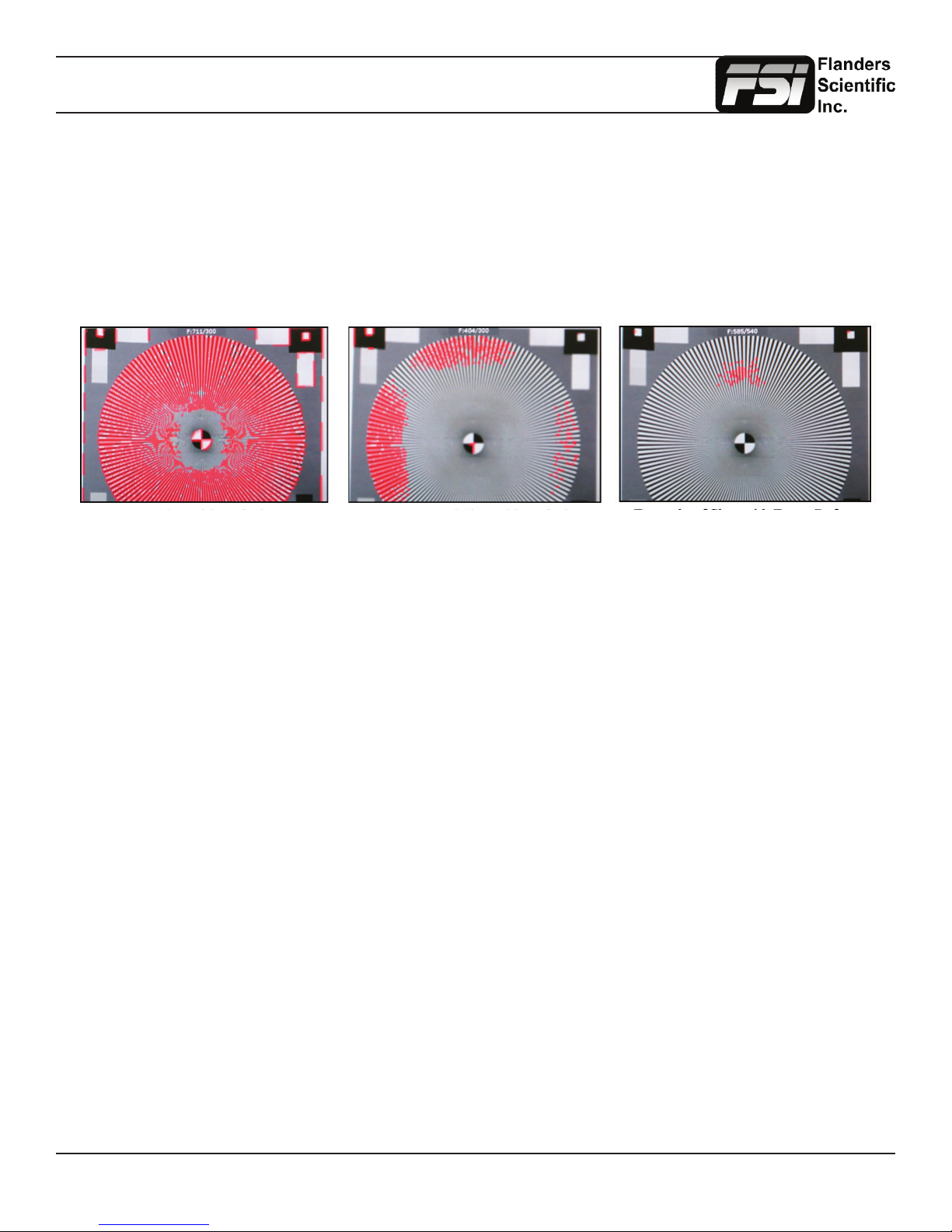
Focus Assist
The focus assist feature is comprised of two main parts: a numerical focus meter and a graphical focus highlight.
The numerical focus meter is shown on screen as your current focus value over your reference focus value (i.e.
560/300). When the focus assist feature is activated the rotary knob labeled Ref POS allows you to adjust the
reference focus value. The reference focus value represents the in-focus threshold for the focus highlight portion
of the focus assist feature. Adjusting the focus reference value higher means that the threshold at which the focus
highlight begins to trace in-focus items with a red boundary will be higher. In other words a greater degree of focus
will need to be achieved before the focus highlight feature is visible on screen as a red trace around in-focus objects.
In Focus Shot with Default Focus
Reference Value
Less Focused Shot with Default
Focus Reference Value
Example of Shot with Focus
Reference Value Turned Up
Level B Variable Wipe
When monitoring a Level B 3Gbps SDI signal (monitor must have 3Gbps SDI Input) comprised of two multiplexed 1.5Gbps
HD-SDI signals the monitor will allow you to view these signals in a vertical or horizontal split screen mode. By activating the
Level B Variable Split function while in split screen mode the positioning of the split can be adjusted using the H POS rotary
knob. To quickly reset the split screen positioning to the default center position simply press down on the H POS rotary knob
while the Level B Variable Wipe function is active. Once your desired split screen wipe position is set you can the Level B
Variable Wipe function off to remove the guide line between the two signals.
Still Frame
This function allows you to freeze a video source at anytime. To unfreeze simply press the function key assigned to Still
Frame a second time.
Zoom
This function zooms in on the incoming source until the entire screen is lled. This is strictly a zooming function and does
not alter the native aspect ratio of the source to ll the screen. When viewing a 4:3 source in Zoom mode on a 16:9 display
the aspect ratio of the visible video will remain 4:3 though the entire 16:9 screen will be lled. Essentially the Zoom mode
results in viewing a 16:9 section of the 4:3 source and is most useful when viewing a letterboxed SD source on a widescreen
display so that the letterboxing is not shown and only the video within the letterboxing is present.
DSLR Zoom
This function is designed to be used with many popular DSLR cameras that have preview/record monitoring output in 1080
& 480 resolutions. When DSLR Zoom is active the 16:9 area that will be recorded is scaled to ll the screen. On DSLR
cameras that switch from 1080 to 480 while recording the DSLR Zoom can be left on and the same correct aspect zoom will
be maintained regardless of whether the DSLR is in preview or recording mode. While DSLR Zoom is active the markers
may also be turned on and will be correct relative to the 16:9 video that will be captured to the camera’s memory card. Please
note it may be necessary to toggle the viewing mode preference (Info button on many DSLRs) to ll the screen correctly.
Return to Table of Contents
14
© 2014 Flanders Scientic, Inc.
 Loading...