

FSD International Commander 115 TC Pilot Operating Handbook

FSD International
Commander 115 TC
Pilot Operating Handbook
Version: 2.0
Revised: December, 2008
Introduction
The complete information on the Commander 115 TC consists of this documents, pleas several
specialized handbooks. All handbooks are available in your Flight Simulator X\FSD
International\Pilot Manuals folder on your hard drive. They may also be accessed through your
Windows Start Menu.
The following is a complete listing of the installed handbooks:
Handbook Description
Panel Handbook Complete manual for operating panel controls and explanation
of their functions
Load Manager Handbook Details all of the functions of the Load Manager and their proper
operation
Realism Module Handbook Full description of the operation and function of the Realism
Module
Totalizer Handbook Detailed description of the functions and usage of the fuel
Totalizer
GNS 480 Manual Complete pilot handbook for the Garmin GNS 480 included with
the Commander
SL30 Manual Handbook for the Apollo NAV2/COM2 radio included with the
Commander
KR 87 Manual Manual for the Bendix King KR 87 ADF radio
ST55X Autopilot Manual Pilot handbook for the STEC ST55X autopilot and inconnected
modules
This handbook is provided with the Commander 115 TC to allow the pilot to attain as much
knowledge about the airplane and its operation as possible. It is not intended as a textbook on
basic flying techniques but is oriented towards those areas specific to the 115 TC. The pilot should
become familiar with the contents of this handbook and use them to guide his operations of the
airplane.
Table of Contents
Introduction ................................................................................................................... 1
1 Descriptive Data........................................................................................................... 5
1.1 Engine................................................................................................................... 5
1.2 Propeller................................................................................................................ 5
1.3 Weights................................................................................................................. 5
1.4 Fuel & Oil Capacity .................................................................................................. 5
1.5 Wing Area/Loadings ................................................................................................ 5
1.6 Performance Speeds................................................................................................ 5
1.7 Takeoff Performance ............................................................................................... 5
1.8 Climb Performance.................................................................................................. 6
1.9 Range ................................................................................................................... 6
For use with Microsoft Flight Simulator only. Not to be used for real-world aviation.
Copyright© 2008 by FSD International. All rights reserved.
- 1 –

FSD International
Commander 115 TC
Pilot Operating Handbook
1.10 Landing Performance ............................................................................................. 6
2 Limitations .................................................................................................................. 6
2.1 Speed Limitations ................................................................................................... 6
2.2 Flap Limits ............................................................................................................. 7
2.3 FLIGHT LOAD FACTOR LIMITS .................................................................................. 7
2.4 Airspeed Indicator Markings ..................................................................................... 7
2.5 AIRSPEEDS FOR EMERGENCY OPERATION .................................................................. 8
2.6 Power Plant and Prop Limitations............................................................................... 8
2.7 Engine Instrument Markings ..................................................................................... 9
2.8 Center of Gravity Limits ........................................................................................... 9
2.9 General Operation Limits by Type............................................................................ 10
2.10 Placards............................................................................................................. 11
3 Emergency Procedures................................................................................................ 12
3.1 ENGINE FAILURES ................................................................................................ 12
3.2 EMERGENCY LANDINGS ......................................................................................... 13
3.3 ICING ................................................................................................................. 15
3.4 LANDING GEAR MALFUNCTION PROCEDURES ........................................................... 16
3.5 ELECTRICAL SYSTEM EMERGENCIES........................................................................ 19
3.6 MISCELLANEOUS ABNORMALITIES .......................................................................... 20
3.7 AMPLIFIED EMERGENCY PROCEDURES..................................................................... 21
4 Normal Procedures ..................................................................................................... 26
4.1 AIRSPEEDS FOR NORMAL OPERATION ..................................................................... 26
4.2 PREFLIGHT INSPECTION ........................................................................................ 27
4.3 EXTERNAL............................................................................................................ 28
4.4 STARTING ENGINE................................................................................................ 30
4.5 BEFORE TAXI ....................................................................................................... 30
4.7 BEFORE TAKEOFF ................................................................................................. 31
4.8 NORMAL TAKEOFF................................................................................................. 31
4.10 BEFORE LANDING ............................................................................................... 32
4.11 LANDING - NORMAL LANDING............................................................................... 32
4.12 SHORT FIELD LANDING........................................................................................ 32
4.13 BALKED LANDING / GO-AROUND........................................................................... 33
4.14 AFTER LANDING.................................................................................................. 33
4.15 SHUTDOWN........................................................................................................ 33
4.16 AMPLIFIED PROCEDURES ..................................................................................... 34
5 Performance .............................................................................................................. 40
5.1 Commander 115 TC Performance and Operating Limitations........................................ 40
6 Airplane and Systems Descriptions................................................................................ 45
6.1 GENERAL ............................................................................................................. 45
6.2 AIRFRAME............................................................................................................ 45
6.3 FLIGHT CONTROLS................................................................................................ 46
6.5 IGNITION SYSTEM ................................................................................................ 49
6.6 EXHAUST SYSTEM................................................................................................. 50
6.7 FUEL INJECTION SYSTEM....................................................................................... 50
6.9 ENGINE COOLING SYSTEM ..................................................................................... 50
6.10 STARTER............................................................................................................ 50
6.12 HYDRAULIC SYSTEMS .......................................................................................... 52
6.13 ELECTRICAL SYSTEM ........................................................................................... 54
6.15 PITOT PRESSURE SYSTEM .................................................................................... 56
6.16 STATIC PRESSURE SYSTEMS ................................................................................ 57
7 Terminology .............................................................................................................. 58
For use with Microsoft Flight Simulator only. Not to be used for real-world aviation.
Copyright© 2008 by FSD International. All rights reserved.
- 2 –

FSD International
Commander 115 TC
Pilot Operating Handbook
For use with Microsoft Flight Simulator only. Not to be used for real-world aviation.
Copyright© 2008 by FSD International. All rights reserved.
- 3 –
FSD International
Commander 115 TC
Pilot Operating Handbook
Copyright© 2008 by FSD International. All rights reserved.
For use with Microsoft Flight Simulator only. Not to be used for real-world aviation.
- 4 –

FSD International
Commander 115 TC
Pilot Operating Handbook
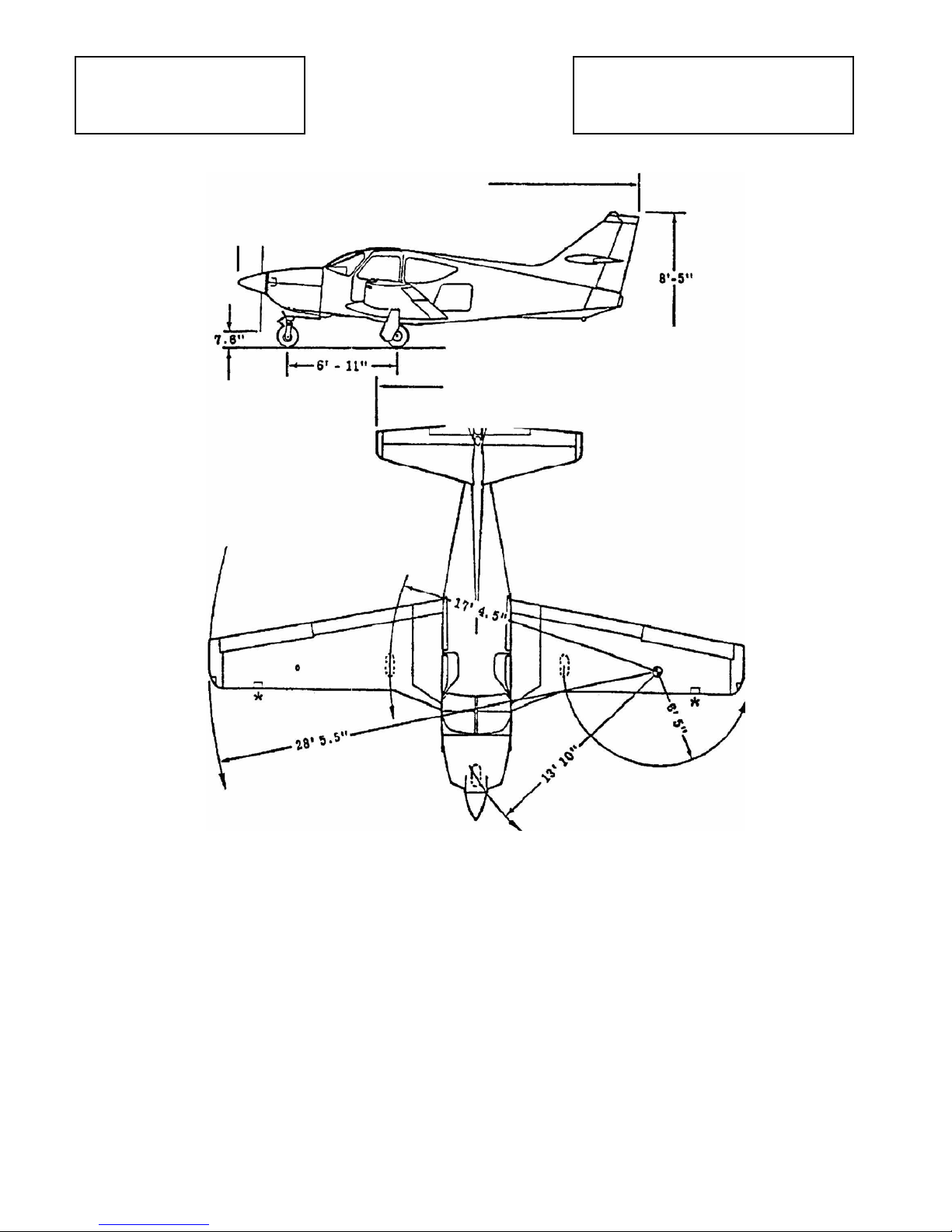
1 Descriptive Data
1.1 ENGINE
Manufacturer Textron Lycoming
Model TIO-540-AG1A
Number of Cylinders 6
Displacement 541.5 cu. in. (8.87 l)
Maximum Power 270 HP @ 2,700 RPM
Recommended TBO 2,000 hours
1.2 PROPELLER
Manufacturer McCauley
Model B3D32C419/82 NHA-5
Type Constant-Speed, Hydraulic
Number of Blades 3
Diameter 77" (1.96 m)
1.3 WEIGHTS
Maximum Ramp 3,260 lbs. (1,478.71 kg)
Maximum Take-off 3,250 lbs. (1,474.17 kg)
Standard Empty 2,102 lbs. (953.45 kg)
Max Baggage
Compartment 200 lbs. (90.72 kg)
Standard Useful Load 1,158 lbs. (525.26 kg)
1.4 FUEL & OIL CAPACITY
Fuel 90 US gal./88 usable
(340.65 liters/333.08 usable)
Oil 8 quarts (7.57 l)
1.5 WING AREA/LOADINGS
Wing Area 152 sq. ft. (14.12 sq. m)
Wing Loading 21.4 lbs./sq. ft.(104.48 kg/sq. m)
Power Loading 12.5 lbs./hp. (5.67 kg/hp)
1.6 PERFORMANCE SPEEDS
Maximum 164 kts. (304 kph)
Performance Cruise (75% Power) 160 kts. (297 kph)
Economy Cruise (65% Power) 155 kts. (287 kph)
Long Range Cruise (55% Power) 149 kts. (276 kph)
Stall (Cruise Configuration) 60 kts. (111 kph)
Stall (Landing Configuration) 54 kts. (100 kph)
1.7 TAKEOFF PERFORMANCE
Ground Roll 1,145 ft. (348.99 m)
Distance over
50 ft. Obstacle 1,985 ft. (605.02 m)
For use with Microsoft Flight Simulator only. Not to be used for real-world aviation.
Copyright© 2008 by FSD International. All rights reserved.
- 5 –

FSD International
1.8 CLIMB PERFORMANCE
Initial S.L. Rate of Climb 1,070 ft./min.(326.14 m/min.)
Service Ceiling 16,800 ft.(5,120.64 m)
1.9 RANGE
Range @ Performance Cruise 855 NM @ 14.3 gph.(54.13 lph)
Range @ Economy Cruise 940 NM @ 12.6 gph.(47.69 lph)
Range @ Long Range Cruise 1005 NM @ 11.2 gph.(42.39 lph)
1.10 LANDING PERFORMANCE
Ground Roll 720 ft. (219.46 m)
Distance over 50 ft. Obstacle 1,200 ft. (365.77 m)
Pilot Operating Handbook
Commander 115 TC
2 Limitations
This section presents the airplane operating limitations, required instrument markings and the
significance thereof, and the required placards. All material included in this section has been
approved by the Federal Aviation Administration. Observance of all operating limitations is required
by the Federal Aviation Regulations. Similarly all required instrument markings and placards must
be maintained in a legible and usable condition on the airplane.
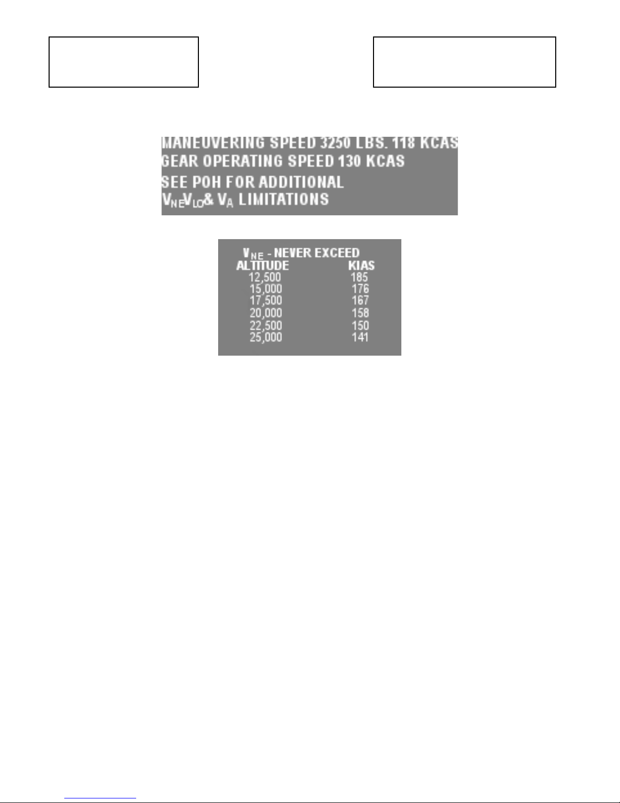
2.1 SPEED LIMITATIONS
SPEED SYMBOL KCAS KIAS SIGNIFICANCE
Never Exceed ASL
12500 ft
16000 ft
20000 ft
24000 ft
Maximum Structural Cruise ASL
12500 ft
16000 ft
20000 ft
24000 ft
Maneuvering
3250 lbs.
2658 lbs.
2023 lbs.
Maximum Flap Extended To
1st flap (9 deg)
2nd flap (25 deg)
Full flap (35deg)
Maximum Landing Gear Operating
Maximum Landing Gear Extended
Maximum Vent Open
VNE
VNO
V
A
VFE
VLO
VLE
---
186
175
161
147
148
139
128
117
118
109
95
150
120
109
130 130 Do not extend or retract
186 187 Do not exceed this speed
130 130 Do not exceed this speed
187
176
161
147
148
139
128
117
118
109
95
151
121
111
Do not exceed this speed
in any operation.
Do not exceed this speed
except in smooth air, and
then only with caution.
Do not make full or abrupt
control movements above
this speed.
Do not exceed these
speeds with the given flap
deflection.
the landing gear above this
speed.
with landing gear
extended.
with storm vent open.
For use with Microsoft Flight Simulator only. Not to be used for real-world aviation.
Copyright© 2008 by FSD International. All rights reserved.
- 6 –

FSD International
2.2 FLAP LIMITS
Approved Takeoff Range: 0° to 20°
Approved Landing Range: 0° to 35
2.3 FLIGHT LOAD FACTOR LIMITS
Flaps 0° +3.8 G's - 0 G
Flaps 35° +2.0 G's - 0 G
2.4 AIRSPEED INDICATOR MARKINGS
MARKING KCAS VALUE OR RANGE SIGNIFICANCE
White Arc
58-114
Full Flap Operating Range. Lower limit is
maximum weight zero thrust stall speed
in the landing configuration. Upper limit is
maximum speed allowable with flaps fully
extended.
Commander 115 TC
Pilot Operating Handbook
Green Arc
Yellow Arc
Red Radial Line
65-160
160-185
186
Normal Operating Range. Lower limit is
maximum weight zero thrust stall speed
with flaps and landing gear retracted.
Upper Inuit is maximum structural
cruising speed.
Caution Range. Operations must be
conducted with caution and only in
smooth air.
Never Exceed Speed. Maximum speed for
all operations.
For use with Microsoft Flight Simulator only. Not to be used for real-world aviation.
Copyright© 2008 by FSD International. All rights reserved.
- 7 –

FSD International
Commander 115 TC
Pilot Operating Handbook
2.5 AIRSPEEDS FOR EMERGENCY OPERATION
Engine Failure After Takeoff:
Flaps Up: maintain 85 KIAS
Wing Flaps 20°: maintain 80 KIAS
Maneuvering Speed:
3250 Lbs 118 KIAS
2600 Lbs 109 KIAS
2023 Lbs 95 KIAS
Maximum Glide:
3250 Lbs 86 KIAS
2600 Lbs 76 KIAS
2023 Lbs 66 KIAS
Precautionary Landing
With Engine Power: approach speed 75 KIAS
Without Engine Power: approach speed 75 KIAS
Flaps : 35°
2.6 POWER PLANT AND PROP LIMITATIONS
Maximum Power: 260 BHP Rating
Engine Operating Limits for Takeoff
and Continuous Operations
Maximum Engine Speed: 2700 RPM
Maximum Cylinder Head
Temperature: 500 °F (260 °C)
Maximum Oil Temperature 245°F (118 °C)
Oil Pressure, Minimum: 25 PSI
Maximum: 115 PSI
Fuel Injector Inlet Pressure
Minimum: 12 PSI Maximum: 45 PSI
Fuel Nozzle Pressure, Maximum: 9.5 PSI, 27.5 gal/hr
Propeller Blade Angle at the
30 Inch Blade Station
Low: 12.6°
High: 33°
For use with Microsoft Flight Simulator only. Not to be used for real-world aviation.
Copyright© 2008 by FSD International. All rights reserved.
- 8 –
FSD International
Commander 115 TC
Pilot Operating Handbook
2.7 ENGINE INSTRUMENT MARKINGS
Instrument RED LINE
MIN
YELLOW ARC GREEN ARC RED LINE
MAX
Manifold Pressure InHg -- -- 10-29 39
Tachometer - RPM -- 2500-2700 2200-2400 2100
Fuel Flow - GPH PSI -- -- 0-22
Cylinder Head Temp. 500-550 -- 200-500 500
Oil Temperature °F -- -- 100-250 250-270
Oil Pressure - PSI 30 90-110 60-90 115
Fuel Pressure - PSI 10 -- 10-58 58
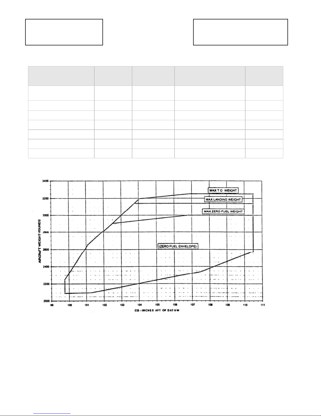
2.8 CENTER OF GRAVITY LIMITS
Copyright© 2008 by FSD International. All rights reserved.
For use with Microsoft Flight Simulator only. Not to be used for real-world aviation.
- 9 –

FSD International
Commander 115 TC
Pilot Operating Handbook
2.9 GENERAL OPERATION LIMITS BY TYPE
KIND OF OPERATION INSTRUMENT SYSTEM OR EQUIPMENT
DAY NIGHT IFR
Alternate induction air system X X X
Alternate static source X X X
Alternator X X X
Altimeter. sensitive X X X
Ammeter X X X
Auxiliary fuel pump X X X
Battery X X X
Circuit breakers X X X
Compass X X X
Flap position indicator X X X
Engine Gauges X X X
Gear locked lights (3) X X X
Gear system. emergency X X X
Gear warn light X X X
Gear warning horn system X X X
Gyro. attitude - - X
Gyro. directional - - X
Gyro. turn & bank indicator or turn coordinator - - X
Instrument panel lighting -- X -
Exterior Lights - X -
Propeller governor X X X
Propeller spinner X X X
Stall warning system X X X
Steering system. nose wheel X X X
Switch. alternator master X X X
Switch. battery master X X X
Tachometer X X X
Trim indicators X X X
Voltage regulator X X X
Voltmeter X X X
Copyright© 2008 by FSD International. All rights reserved.
For use with Microsoft Flight Simulator only. Not to be used for real-world aviation.
- 10 –
FSD International
2.10 PLACARDS
Commander 115 TC
Pilot Operating Handbook
For use with Microsoft Flight Simulator only. Not to be used for real-world aviation.
Copyright© 2008 by FSD International. All rights reserved.
- 11 –

FSD International
Commander 115 TC
Pilot Operating Handbook
3 Emergency Procedures
Emergencies caused by airplane or engine malfunctions are rare if proper preflight inspections and
maintenance are practiced. Enroute weather emergencies can be minimized or eliminated by cardul
flight planning and good judgment when unexpected weather is encountered. Should an
emergency arise, the basic guidelines described in this section are to be applied as necessary to
alleviate the problem.
The procedures contained herein are not intended to constitute basic flight instruction but are
intended to supplement those principles relating to emergencies that each pilot acquires in the
process of learning to fly and obtaining FAA pilot certification.
Checklists are provided to assist a pilot where it would be reasonable for a pilot to refer to one.
Where reference to a checklist would be impractical, or where the material is not amenable to a
checklist form, or where additional material is helpful, amplified procedures are provided following
the checklist section.
3.1 ENGINE FAILURES
3.1.1 ENGINE FAILURE DURING TAKEOFF ROLL
Throttle - IDLE
Brakes - APPLY
Flaps - RETRACT
Mixture - IDLE CUT-OFF
Ignition - OFF
Battery Master Switch - OFF
3.1.2 ENGINE FAILURE IN FLIGHT
Airspeed - MAINTAIN 86 KIAS
Auxiliary Fuel Pump - ON - CHECK PRESSURE
Alternate Induction Air - ON
Mixture - SET FULL RICH
Fuel Selector - SELECT FULLEST TANK
Ignition Switch - CHECK BOTH
3.1.3 IN-FLIGHT ENGINE RESTART PROCEDURES
[NOTE : If propeller stops, use normal starting procedures.]
Airspeed - MAINTAIN 86 KIAS
Fuel Selector - SELECT FULLEST TANK
[NOTE : Do not use the BOTH position. Selecting fullest tank will minimise start time]
Auxiliary Fuel Pump - ON
Mixture - RICH
Ignition Switch - CHECK BOTH ON
Throttle - AT LEAST 1/2 OPEN
For use with Microsoft Flight Simulator only. Not to be used for real-world aviation.
Copyright© 2008 by FSD International. All rights reserved.
- 12 –

FSD International
Commander 115 TC
Pilot Operating Handbook
After engine has restarted:
Throttle - SET AS REQUIRED
auxiliary Fuel Pump - OFF
Mixture - LEAN as required
_______________________________________________________________________________
______
3.2 EMERGENCY LANDINGS
3.2.1 EMERGENCY LANDING WITHOUT ENGINE POWER
Seatbacks - UPRIGHT, LOCKED
Seats, Belts & Harnesses - SECURE
Loose Objects - SECURE
Emergency Locator Transmitter - ON
Transponder - CODE 7700
Airspeed - MAINTAIN 85 KIAS (flaps UP)
MAINTAIN 75 KIAS (flaps 35 Deg)
Auxiliary Fuel Pump - OFF
Fuel Selector - OFF
Landing Gear - DOWN, CHECK LOCKED
[NOTE : If the landing site chosen appears to have an extremely soft surface, recommended that
landing gear remains retracted.]
Mixture - IDLE CUT-OFF
Ignition Switch - OFF
Wing Flaps - 35 Deg (recommended)
Battery & Alternator &
Master Switches - OFF when landing assured.
[NOTE : Stall warning will not be available with electrical system turned off].
Touchdown - TAIL LOW
Brakes - AS REQUIRED
For use with Microsoft Flight Simulator only. Not to be used for real-world aviation.
Copyright© 2008 by FSD International. All rights reserved.
- 13 –

FSD International
Commander 115 TC
Pilot Operating Handbook
3.2.2 PRECAUTIONARY LANDING WITH ENGINE POWER
Seatbacks - UPRIGHT, LOCKED
Seats, Belts & Harnesses - SECURE
Loose Objects - SECURE
Sharp objects in clothing - REMOVE & STOW
Radio - TRANSMIT MAYDAY on area frequency and 121.5 MHz (if time permits)
Emergency Locator
Transmitter - ON (if circumstances so warrant)
Transponder - CODE 7700 (if circumstances so warrant)
Airspeed - MAINTAIN 85 KIAS (flaps UP)
MAINTAIN 75 KIAS (flaps 35 Deg)
SURVEY Selected Landing Site - OVERFLY, noting terrain, obstacles & hazards
SWITCHES ALL SWITCHES (except battery & alternator masters & ignition) - OFF
Auxiliary Fuel Pump - OFF
Fuel Selector - BOTH
Landing Gear - DOWN, VERIFY LOCKED
Mixture - FULL RICH
Propeller Control- FULL INCREASE RPM
Flaps - 35 Deg (recommended)
Power - AS REQUIRED
Airspeed - 75 KIAS
Battery & Alternator &
Master Switches - OFF when landing assured.
[NOTE : Stall warning will not be available with electrical system turned off]
Touchdown - TAIL LOW
Brakes - AS REQUIRED
3.2.3 DITCHING
[NOTE : AIRCRAFT HAS NOT BEEN TESTED IN ACTUAL DITCHING. FOLLOWING ARE AIRCRAFT
MANUFACTURERS RECOMMENDATIONS]
Seatbacks - UPRIGHT, LOCKED
Seats, Belts & Harnesses - SECURE
Loose Objects - SECURE
Sharp objects in clothing - REMOVE & STOW
Radio - TRANSMIT MAYDAY on area frequency and 121.5 MHz (if time permits)
Emergency Locator
Transmitter - ON (if circumstances so warrant)
Transponder - CODE 7700 (if circumstances so warrant)
Airspeed - 85 KIAS (flaps UP)
75 KIAS (flaps 35°)
Auxiliary Fuel Pump - OFF
Fuel Selector - BOTH
Landing Gear - UP
Mixture - FULL RICH
Propeller Control - FULL INCREASE RPM
For use with Microsoft Flight Simulator only. Not to be used for real-world aviation.
Copyright© 2008 by FSD International. All rights reserved.
- 14 –

FSD International
Commander 115 TC
Pilot Operating Handbook
Flaps - 20 Deg (recommended)
Cowl Flap - CLOSED
Power - SET TO MAINTAIN 300 FT/MIN DESCENT AT 75 KIAS
Approach
High Winds, Heavy Seas - INTO WIND
Light Winds, Heavy Swells - PARALLEL TO SWELLS
Touchdown - LEVEL AITITUDE AT 300 FT/MIN DESCENT. Do not flare.
Airplane - EVACUATE.
[NOTE : If necessary, open vent window(s) and flood cabin to equalize pressure so that cabin doors
can be opened. ]
Life Vests, Raft - INFLATE *OUTSIDE* AIRCRAFT
3.3 ICING
3.3.1 INADVERTENT ICING ENCOUNTER
1. Pitot Heat - ON
2. Defrost Control- FULL ON
3. Engine RPM - INCREASE TO 2700 (enrich mixture as required)
4. Alternate Air - PULL ON
5. Course - REVERSE OR ALTER as required to avoid icing.
Evasive action should be initiated immediately when icing conditions are encountered.
6. Altitude - CHANGE to an altitude less conducive to icing.
IF ICING CONDITIONS CANNOT BE ESCAPED:
6. Airplane - LAND AT NEAREST AIRPORT. With extremely rapid ice build-up, plan for an
off-airport forced landing.
7. Approach Speed - INCREASE 5 TO 20 KIAS depending on ice accumulation.
3.3.2 OBSTRUCTED STATIC SOURCE
1. Alternate Static Source - ON
2. Heat & Defrost Controls - ON
3. Cabin Air Vents - CLOSED
3.3.3 OBSTRUCTED PITOT SOURCE
1. Pitot Heat Switch - ON
NOTE
Use familiar pitch attitude/power settings to achieve desired airspeeds if airspeed indicator
readings appear to remain unreliable.
For use with Microsoft Flight Simulator only. Not to be used for real-world aviation.
Copyright© 2008 by FSD International. All rights reserved.
- 15 –

FSD International
Commander 115 TC
Pilot Operating Handbook
3.4 LANDING GEAR MALFUNCTION PROCEDURES
3.4.1 LANDING GEAR FAILS TO RETRACT
(Green Gear Locked And/Or Red Gear Warn lights Remain On)
1. Gear Motor Circuit Breaker - CHECK IN
2. Emergency Gear Extension Valve Knob - CHECK FULL UP
3. Landing Gear Switch - RECYCLE
If landing gear still fails to retract:
4. Landing Gear Switch - DN
5. Landing Gear Lights - VERIFY 3 GREEN
6. Airplane - LAND AS SOON AS PRACTICAL for repairs.
3.4.2 LANDING GEAR FAILS TO EXTEND
(Green Gear Locked Light(s) Fails To Illuminate and Red Gear Warn Light Remains On)
1. Gear Light Press- To-Test Switch - CHECK green light bulb integrity
2. Gear Motor Circuit Breaker – CHECK IN
3. Landing Gear Switch - RECYCLE
If an unsafe indication persists, proceed as follows:
4. Gear Motor Circuit Breaker - PULL
5. Landing Gear Switch - CHECK DN
6. Wing Flaps – FULL EXTEND
NOTE
Gear Warning horn will activate as flaps exceed approximately 20°
7. Power - MINIMUM FOR FLIGHT CONDITIONS
8. Airspeed - REDUCE TO 80 KIAS.
9. Emergency Extension Valve Knob - PULL OUT & PUSH DOWN
10. Landing Gear Lights - VERIFY 3 GREEN
NOTE
If the nose gear fails to extend, it may be necessary to cycle the rudder pedals, reduce power,
and/or reduce the airspeed.
3.4.3 GEAR WARN LIGHT ILLUMINATES
(Gear Up Selected)
1. Gear Motor - CHECK AUDIBLY for operation.
2. Airspeed - CHECK for normal gear retracted performance.
For use with Microsoft Flight Simulator only. Not to be used for real-world aviation.
Copyright© 2008 by FSD International. All rights reserved.
- 16 –

FSD International
Commander 115 TC
Pilot Operating Handbook
LANDING GEAR MALFUNCTION PROCEDURES (CON'T)
3. Gear Motor Circuit Breaker -- PULL if gear appears to be retracted and flight is to be
continued to a maintenance facility.
NOTE
For landing gear extension at destination reset the Gear Motor Circuit Breaker.
3.4.4 GEAR WARN LIGHT ILLUMINATES
(Gear On Selected)
1. Landing Gear Locked Lights - CHECK 3 GREEN
2. Gear Motor - CHECK AUDIBLY for operation.
3. Gear Motor Circuit Breaker -- PULL until just prior to landing, then RESET.
3.4.5 GEAR UP LANDING
1. Seatbacks - UPRIGHT
2. Seats, Seat Belts, Shoulder Harnesses -- SECURE
3. Loose Objects - SECURE
4. Radio -- TRANSMIT MAYDAY to A TC or on 121.5 mHz (if circumstances so warrant)
5. Emergency Locator Transmitter - ON (if circumstances so warrant)
6. Transponder - CODE 7700 (if circumstances so warrant) 7. Airspeed -85 KIAS (flaps UP)
1. 75 KIAS (flaps 20°)
7. Fuel Selector Valve - BOTH (OFF if power is oft)
8. Mixture - FULL RICH (IDLE CUT-OFF if power is oft) 10. Propeller Control - FULL
INCREASE RPM
11. Wing Flaps - 20° (recommended)
12. Touchdown -- TAIL LOW
13. Elevator Control - FULL AFT
14. Mixture -- IDLE CUT-OFF
15. Fuel Selector Valve - OFF
16. Airplane - EVACUATE after coming to stop.
3.4.5 LANDING WITHOUT POSITIVE INDICATION OF GEAR LOCKING
1. Before Landing Checklist -- COMPLETE
2. Loose Objects -- SECURE
3. Gear Motor Circuit Breaker -- IN
4. Approach -- NORMAL (full flap)
5. Landing -- TAIL LOW as SMOOTHLY as possible
6. Braking -- MINIMUM necessary.
7. Taxi -- SLOWLY clear of runway.
8. Engine -- SHUTDOWN before inspecting landing gear system.
For use with Microsoft Flight Simulator only. Not to be used for real-world aviation.
Copyright© 2008 by FSD International. All rights reserved.
- 17 –

FSD International
Commander 115 TC
Pilot Operating Handbook
LANDING GEAR MALFUNCTION PROCEDURES (CON'T)
3.4.6 LANDING WITH ONE RETRACTED OR UNLOCKED MAIN GEAR
(Or Flat Main Tire)
1. Before Landing Checklist - COMPLETE
1. NOTE
2. If it is suspected that a tire is defective prior to retraction, it is recommended that the gear
remain extended.
3. Loose Objects - SECURE
4. Approach - NORMAL (full flap)
5. NOTE
6. Select a runway with a crosswind component from ihe same side as the good main
gear/tire.
7. Touchdown - ON GOOD MAIN GEAR FIRST
8. Aileron - BANK AWAY FROM DEFECTIVE GEARITIRE as long as possible.
9. If one main gear was still retracted, or the airplane begins to lower the wing on the
defective
10. Mixture - IDLE CUT-OFF
11. Fuel Selector - OFF
12. Battery & Alternator Master Switches - OFF
3.4.7 LANDING WITH A DEFECTIVE NOSE GEAR
(Or Flat Nose Tire)
1. Before Landing Checklist - COMPLETE
NOTE
If it is suspected that a tire is defective prior to retraction, it is recommended that the gear remain
extended.
2. Loose Objects - SECURE
3. Approach - NORMAL (full flap)
4. Touchdown - SLIGHTLY TAIL LOW
5. Rollout - NOSE HIGH
6. If the nose gear was still retracted, or the airplane begins to lower the nose toward the
ground:
7. Mixture -- IDLE CUT-OFF
8. Fuel Selector – OFF
9. Battery & Alternator Master Switches - OFF
For use with Microsoft Flight Simulator only. Not to be used for real-world aviation.
Copyright© 2008 by FSD International. All rights reserved.
- 18 –
 Loading...