

Page 1
OCTOBER, 2012
SEG Series
OIL-INJECTED ROTARY SCREW COMPRESSORS
CAP881
REV.A
OPERATOR
MANUAL
SEG-5 SEG-10
SEG-7.5 SEG-15
Page 2

CAP881
Table of Contents
1.0 Introduction
-Preface ………………………………………………………………………….. 3
-Safety …………………………………………………………………………… 7
2.0 Receiving and Installation
- Installation / Precaution …………………………...…………………………… 9
-Electrical …………………………………..…………………………………… 19
3.0 Principle of Screw air compressor
- General …...……………………………………………………………..…….. 21
- Air/Oil Flow………………………………………………………………......... 22
4.0 System Flow Chart and Components Function
- System Flow Chart ……………………………………………………………. 23
- Description …………………………………………………………………….. 25
- Protection / Warning …………………………………………….……………. 27
- Control Systems / Electrical Circuit …………………………….…………..... 27
-Controller Operating Panel……………………………………………….. 29
5.0 Operation
- Inspection …………………………………………….……………………… 30
- Storage ………………………………………………………………………… 31
6.0 Maintenance
- Maintenance Intervals ………………………………………………………... 32
- Air Filter / Oil Filter ………………………………………………………….. 33
- Air / Oil Separator …........................................................................................... 34
- Lubricant ………...……………………………………………………….…... 35
- Oil Analysis ………...……………………………………………….….......... 35
- Thermostatic & Minimum Pressure Valves …………………………….…….. 36
- Belts …………………………...……………………………………….……... 36
- Sheave...……………………………..………………………………….….…... 37
-Fan / Motor ………………………………………………………….………… 38
- Bearings……….…………………………………………..………………….. 39
- Air end / Motor Removal ………………..……………………………………. 39
7.0 Trouble Shooting ………………………………………………………………… 40
8.0 Maintenance Log ………………………………………………………………… 43
- 2 -
Page 3

CAP881
△
!
Danger
Danger is used to indicate presence of a hazard that will cause
severe personal injury, death, or substantial property damage.
△
!
Warning
Warning is used to indicate the presence of a hazard, which can
cause severe personal injury, or substantial property damage.
△
!
Caution
Caution is used to indicate the presence of a hazard, which can
cause personal injury, or property damage.
_ ____
_ ____
_ ____
Supplementary instruction for operation and maintenance
Reference
1.0 Introduction
Preface
Warning
Read this manual before assembly or operation of the compressor. Become
familiar with this information, its safety instructions and its operation before
starting unit. Serious personal injury may result if safety and/or operational
information is not understood or comprehended.
◎ Alert signals
Description of signals
- 3 -
Page 4
CAP881
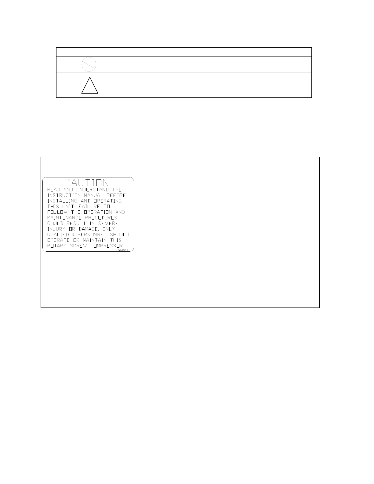
Symbols
Description of symbols
Prohibited
Extreme caution
Operation manual
Follow the instructions before using this compressor.
Confirm the direction of motor rotation before
startup.
See Section 5.5 for instructions
Caution before startup
To restart compressor after a long period of being inactive,
rotate air end manually with the power off. If it is difficult
to rotate, contact FS CURTIS directly.
Description of symbols – cont.
◎ Warning Labels are placed on the machines.
If the labels are not clear or missing, contact FS CURTIS directly.
◎ Explanations of safety symbols
- 4 -
Page 5

CAP881
Danger: Electric circuits
Danger: Rotating parts
Danger: Hot or noxious gas outlet: Not Breathable
Danger: Heat. Do not touch hot areas
Rotation
- 5 -
Page 6
CAP881
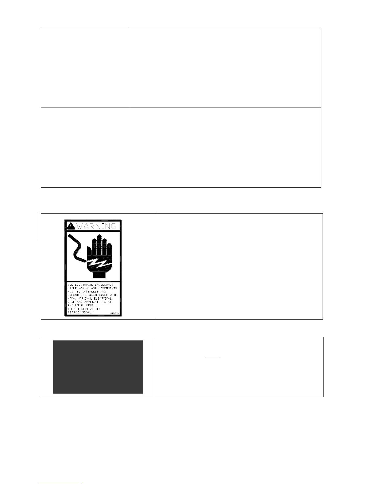
Read instruction
Hearing protection required
Turn off power supply before maintenance or service
around electric equipment, such as starter, and motor.
Remove the 2 RED Shipping Brackets that secure
the motor/airend to the base frame before test run
or startup. Contact FSCURTIS or distributor for
assistance if necessary.
- 6 -
Page 7

CAP881
Safety
1. Become familiar with this manual and follow the instructions before
operating the compressor.
2. If any malfunctions or trouble has occurred, do not run compressor until problem is
resolved.
3. Make sure the compressor has been disconnected before servicing or changing
parts. Lockout and tagout prior to maintenance.
4. To ensure human safety and protect the facility from damage, an electrical ground is
necessary.
5. Wear proper apparel during operation. Protective clothing should be worn such as
facemask or safety goggles and non slip footwear.
6. Optional Dryer should be connected to separate 120V power source and follow
Lockout/Tagout procedures for inspection or maintenance.
- 7 -
Page 8

CAP881
Caution
- Users that neglect these safety precautions run the risk of serious injury or death.
- Fingers and clothing must be kept away from rotating parts.
- Compressed air from this machine cannot be used for pharmaceutical, food or health
requirements without further treatment.
- Release all pressure from the system prior to maintenance.
- Electric shock could be fatal.
- Grounding of starter and motor is necessary. Choose grounding cable according to
the power range of the compressor.
- Lockout and tagout power supply before working on control panel.
- Lockout and tagout power supply before inspection and maintenance - compressor is
controlled by PID and may start automatically according to the setting.
- Optional Dryer should be connected to separate 120V power source and follow
Lockout/Tagout procedures for inspection or maintenance.
Additional Safety information for Air Compressors
Like all power tools, there is danger associated with operating this equipment. Accidents are
frequently caused by lack of familiarity or failure to pay attention. Use this machine with
extreme caution. If normal safety precautions are overlooked or ignored, serious personal injury
may occur.
The following are some safety suggestions that users should observe:
Warning
- Users who neglect the following instructions may damage the compressor.
- Lockout and tagout the compressor if maintenance is needed.
- Lockout and tagout power supply before inspection and maintenance - compressor is
controlled by PID and may start automatically according to the setting.
- Optional Dryer should be connected to separate 120V power source and follow
Lockout/Tagout procedures for inspection or maintenance.
- Relief valve is necessary for air piping larger than 1/2”.
- Do not exceed the rated discharge pressure on nameplate during operation.
- The enclosure should be in place prior to operation
- 8 -
Page 9

CAP881
2.0 Receiving and Installation
A. Receiving
1. Check that your shipment matches your order.
2. Check for any damage that may have occurred during shipment.
B. Installation.
In order to ensure proper installation and trouble free operation with minimal maintenance:
1. Select a location where light is adequate enough to operate, maintain, and inspect the
compressor.
2. A clean, low relative humidity and well-ventilated area is best for safe operation.
The ambient temperature should be kept below 104°F (40℃). The air delivery of the
compressor will decrease as the temperature gets higher.
3. Reserve space for maintenance, the distance between the compressor and the wall or
other equipment must be greater than 28 inches (71 cm).
4. There must be at least 3 feet of clearance between top of compressor and any over head
obstructions.
5. To avoid damage to the unit, lift using eyebolts and straps as shown in Figure 2.1
Figure 2.1
- 9 -
Page 10

CAP881
C. Precaution for piping foundation and cooling system
1. Air piping
(1). Install required accessories.
(2). Main piping should have 1˚- 2˚ slope away from compressor to drain the condensate.
(3). Pressure drop of piping must not exceed 5% of discharge pressure. Select larger piping
than required for better efficiency.
(4). Branch line must be located at the top side of main piping to avoid the condensate from
flowing to the equipment.
(5). To prolong service life of pneumatic tools, install an air filter regulator unit on the
outlet.
(6). Do not randomly reduce the size of the main piping. Use the proper reducer if
necessary to reduce pressure losses.
(7). The ideal installation arrangement of air solution is air compressor + air tank + dryer.
The air tank is capable of draining some of the condensate and cooling down the
temperature of compressed air. This will lead to more efficient dryer operation.
(8). If the air requirement is large in a short period of time, install a higher volume air tank
to reduce the frequency of full/off load control.
(9). The ideal main piping is constructed around the factory as a loop which is better for
delivering compressed air from both sides at any point.
2. Foundation
(1). Select a solid and level surface to install the compressor.
(2). There is no need to construct a base for the screw air compressor since the vibration is
relatively small. However, the area must be flat and strong enough to support the
weight of the unit.
3. Cooling system
Install an air-cooled compressor in a well-ventilated area to avoid high temperature
shutdown. If placed in a sealed room, air extracting and removal apparatus is required
and its capacity must be larger than the cooling fan in the compressor.
- 10 -
Page 11

CAP881
- 11 -
Page 12

CAP881
- 12 -
Page 13

CAP881
Page 14

CAP881
- 14 -
Page 15

CAP881
Page 16

CAP881
- 16 -
Page 17

CAP881
- 17 -
Page 18

CAP881
- 18 -
Page 19
CAP881
Model
230 V
460 V
SEG-5
Amp Draw
16.1
8.1
SEG-7.5
Amp Draw
21.6
10.8
SEG-10
Amp Draw
28.8
14.4
SEG-15
Amp Draw
41.6
20.8
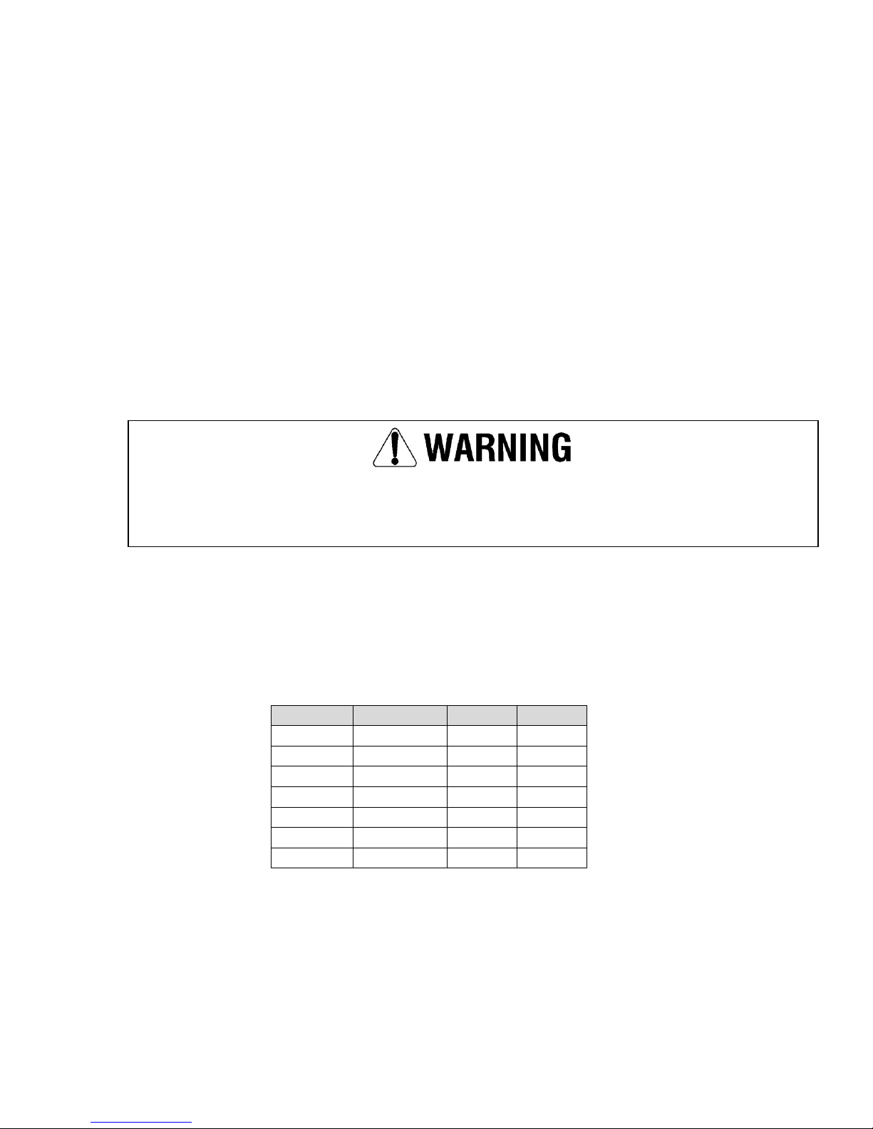
Failure to properly ground compressor package could result in controller malfunction.
D. Electrical
A qualified electrician in compliance with standards and local codes should do all electrical
wiring. Be sure to investigate local requirements before installing the compressor. Refer to
the wiring diagram before starting any work.
The power supply should be adequate and free of parasitic loads that may cause a low
voltage condition during the operation of the compressor; otherwise, there may be nuisance
electrical shutdowns. This equipment requires a properly grounded electrical disconnect
switch.
We recommend the use of time delay fuses in a fusible disconnect for isolating the unit. This
disconnect should be located so an operator can disconnect the unit without being near the unit
in case of an emergency. We also recommend the use of a lockout/tagout to help insure safety
during maintenance of the compressor. Per the National Electric Code the time delay fuses
should be sized at 175% of the full load amperage (FLA) found on the motor nameplate.
Consult the Code if you want to use another style of branch circuit protection.
All internal wiring has been done at the factory. Wiring of the power supply to the
compressor should be done by a qualified electrician to comply with the National
Electric Code, state code, and any local codes in accordance with the wiring
diagram specific to your compressor model shown in the included wire diagram.
Chart of Unit Max Amp Draw (Motor SFA)
Figure: 2-1
Note: Optional Dryer should be connected to separate 120V power source and follow
Lockout/Tagout procedures for inspection or maintenance.
- 19 -
Page 20

CAP881
- 20 -
Page 21
CAP881
INLET
DISCHARGE
MAIN ROTOR
SECONDARY
ROTOR
A B C
3.0 General Description
COMPRESSOR
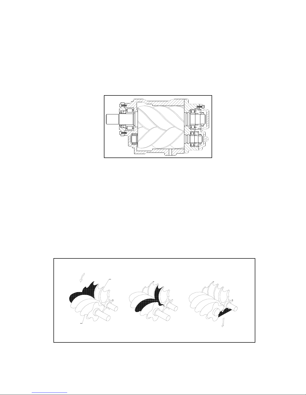
The compressor assembly is an oil flooded positive displacement, single stage, helical screw type
unit consisting of two rotors or screws supported axially by roller bearings and enclosed in a
housing or stator as depicted in the sectional view Figure 3-1.
Figure 3-1
Compressor Assembly
In operation, as depicted below in the compression cycle (Ref. Figure 3-2), air enters the compressor
through the inlet port becomes trapped between the helical lobes of the main rotor and the matching
grooves of the secondary rotor (A). As the rotors turn air is trapped in the cavity created by the
mashing lobe and groove and reduced in volume or “compressed”. It is then pushed through the
successive cavities (B) until it reaches the discharge end of the compressor (C) and is sent to the oil
separator.
During the compression cycle, oil is injected into the compressor for the purpose of dissipating the
heat of compression and to seal the internal clearances. The compressed air laden with oil leaves the
compressor through the discharge port and enters a reservoir where the oil and air are separated. This
process delivers a smooth flow of compressed air at the desired pressure.
Figure 3-2
Compression Cycle
- 21 -
Page 22

CAP881
22
AIR/OIL FLOW
Air enters the compressor through the air filter and air inlet valve where it is mixed with oil. After
compression, the air/oil mixture is discharged into the oil receiver tank. The oil is removed as the air passes
through the Air/Oil Separator element. Oil collected at the bottom of the separator element is returned to the
inlet of the compressor through the scavenger line that is equipped with a sight glass for monitoring the flow
of oil to determine when separator replacement is necessary. The coalesced air then passes through the
minimum pressure valve set to maintain a minimum of 65 PSI in the oil separator to ensure a sufficient flow
of oil to the compressor. The compressed air is discharged to its point of use or enters the aftercooler on
SEG-10 & 15 models where it is then cooled and discharged to its point of use.
A sufficient amount of oil is stored in the Oil Receiver Tank and is forced by the pressure of compression
from the separator to the thermal by-pass valve, which regulates its flow into the oil cooler depending on the
temperature of the oil. The thermal valve will open when the oil reaches a predetermined temperature
allowing the hot oil to enter the cooler. Oil, which has not reached this temperature setting will by-pass the
cooler.
The oil is then filtered and sent to the compressor to initiate the compression cycle. The oil also serves as
lubrication for the compressor bearings.
Page 23

CAP881
23
4.0 System flow diagram and components function
A. System flow diagram and components function
SEG-5 & 7.5 System Flow Diagram
Page 24

CAP881
24
SEG-10 &15 System Flow Diagram
Page 25

CAP881
25
B. Description of system flow chart and component function
1. Air flow path (refer to the flow chart for each type)
1.1. After dust is removed by the intake filter, clean air goes through the air inlet valve into the
compression chamber and is mixed with oil. The mixture is compressed and delivered into the oil
receiver tank, Air/Oil Separator, minimum pressure valve, (and after cooler on SEG-10 & 15
models only).
1.2. Function of parts in the air flow path
(1). Air intake filter
Air intake filter is a suction filter which is a special-purpose air cleaner of the air compressor. For
normal environmental use, clean out the dust on the element every 2,000 hours of operation. Do
not use compressed air.
(2). Air Inlet Valve
On/Off Load Control:for SEG-5/SEG-7.5/SEG-10/SEG-15 models
The solenoid valve is switched by different capacity controls such as: start, stop, off load. Each
will move the piston of the intake valve. The minimum pressure valve (MPV) keeps minimum
pressure to maintain oil circulation.
When system pressure is less than the unload setting value, the solenoid valve is activated and the
air inlet valve opens fully. When the value is reached, the intake valve closes and the compressor is
then running off load.
(3). Temperature Sensor
Lack of oil in circulation will induce high discharge temperature. It displays on the panel through
the signal from the thermal couple. General setting value is 212°F (100℃). Do not operate the unit
over this temperature otherwise a trip will occur.
(4). Oil Receiver
There is a sight glass on the bottom side of the receiver. Maintain the oil level between H-L.
On the bottom there is a drain valve, remember to drain condensate water every time before
startup. In addition, an oil fill hole for oil replacement is on the tank as well.
The larger cross-section area design of this tank will slow down the compressed air,
this is known as the first stage of air oil separation.
(5). Air/Oil Separator
Refer to the description on oil flow path.
(6). Solenoid Valve
During start, stop, or off load operation, this valve will release pressure to ensure the air end starts
without back pressure or stops under off load operation.
(7). Minimum Pressure Valve
Minimum pressure valve is located at the outlet air discharge from Air/Oil Fines Separator Tank.
Operating pressure is set at around 65 PSIG. The functions of minimum pressure valve are shown
below:
A. To build up oil circulation pressure and operating temperature at start.
B. When pressure is over 65 PSIG, it will reduce flow rate passing and protect air/oil separator
from damage due to large pressure difference and increase oil separator efficiency.
C. Prevent back flow under off load running.
(8). After Cooler (On SEG-10 & 15 Models Only)
The compressed air is circulated through the aftercooler which is cooled by the blower attached to
the main motor shaft. Generally discharge air temperature is 27°F above ambient temperature.
Environment is a crucial factor for air-cooled type air compressors. Install in a
well-ventilated area.
Page 26

CAP881
26
2. Oil flow path (refer to the flow chart of each type)
(1). Description of oil injection flow chart
Pressure in the separator pushes oil into the oil cooler and then passes through the oil filter for
filtration after being cooled down. Oil flow then goes into compression chamber from the bottom of
air end and also goes to the bearing on the discharge side for lubrication. The compressed air and oil
mixture is delivered to the Air/Oil Separator which then passes through the filter element separating
the oil from the air and discharging the oil back to the oil receiver.
(2). Volume of oil injection
The purpose of oil injection in an oil flooded screw compressor is to dissipate the heat away in the
process of air compression.
(3). Function of the parts in the oil flow system
A. Oil Cooler
The function of the oil cooler is similar to the air cooler. Oil is circulated through the oil cooler to
dissipate heat with additional cooling from the blower fan. Environment is a crucial factor for
air-cooled type compressors; install unit in a well-ventilated area. Clean the dust on the fins of
radiator periodically with compressed air or with solvent.
B. Oil Filter
Oil filters help get rid of metallic particles, and sludge from compressor oil in order to protect
bearings and rotors. After the first 500 hours of operation is reached, follow the instructions for
replacement. Failure to do so may result in lack of oil which will lead to high discharge temperature
and shorter bearing life.
C. Air/Oil Separator
a. Function
The filter element of the air/oil fines separator is made by multiple layers of filtration materials.
Most of the oil mist in the compressed air is filtered out through the separator filter element. The
life span of the air/oil separator filter element is affected greatly by lubricant grade and condition.
Use CurtisLubePlus FSC- 8000 in order to maintain your warranty. There is a pressure sensor and a
minimum pressure valve at the air/oil separator outlet. Compressed air is fed through the air/oil
separator, to the minimum pressure valve and discharged to its point of use, or to the after cooler
(on SEG-10 & 15 models) prior to discharge. Oil collected by the air/oil separator will return to the
suction side of the air end to avoid oil carry over.
b. Air/Oil Separator Filter Element needs to be replaced when:
1. Oil carry over increases.
2. Amp draw increases.
Page 27

CAP881
27
E. Protection and warning
1. Motor overload protection
When the Amp draw exceeds the upper limit of the overload relay setting, the unit will shutdown
automatically. Re-setting the unit is required prior to the next start. The relay limit has been set by the
factory. To maintain normal operation, do not change the limit setting without consulting the factory.
If motor overloads during operation, contact manufacturer immediately to prevent
damage to the motor.
2. Discharge temperature protection
Discharge temperature setting is 212°F (100℃). If the temperature exceeds 212°F (100℃), the
compressor will trip. One of the most common reasons for high discharge temperature is an issue with
the oil cooler. For an air-cooled compressor, if the radiator is clogged, oil temperature goes up resulting
in a compressor trip because cooling air can’t pass through the radiator. Clean the dust off the fins of the
radiator periodically with compressed air or with a solvent if the situation gets worse.
The air compressor is designed to operate up to 104°F (40℃) ambient temperature which makes it
necessary to place the unit in a well-ventilated area. When the compressor is tripped due to a high
discharge temperature, the system is unable to restart unless the reset button is pressed after the
system cools down.
F. Control system and electric circuit
1. Control system
(1)Start & Overload Operation
After motor start, the solenoid valve is energized to keep the intake valve open and building pressure.
When pressure reaches 65 PSIG, the minimum pressure valve (MPV) opens allowing compressed air
to discharge.
(3)Off load operation
When the discharge pressure reaches the unload pressure setting, the solenoid valve is de-energized
and blows down air and closes the intake valve. Compressor is running in off load condition.
(4)Stop
Pressing the “STOP” button will de-energize the solenoid valve and a close the intake valve. As a
result the system blows down into the atmosphere. Motor stops after 15 seconds (default setting)
(5)Emergency stop
When the E-Stop button is activated, the motor will stop immediately and an E-Stop warning will
display on the control panel. The blow down line opens, and the intake valve closes to prevent
lubricant from coming out of the air end. Only use the E-Stop button in an emergency and the
“Stop” button for normal shut down use.
Page 28

CAP881
28
(6)Auto stop over time period
If there is no demand for compressed air, the compressor runs in “off load” mode until it stops after a
set time period and remains in Stand-by Mode. The compressor starts automatically to meet air
demand. There is an AutoStop warning sign displayed on the controller. The unit should not start
more than 6 times per hour. This is controlled by AutoStop time setting on AIMS controller.
Minimum is setting is 10 minutes, default is 15 minutes.
2. Electric Circuit
The motor uses across the line start. The compressor system is operated by an AIMS controller
3. Controller:
Refer to the AIMS Controller Manual (CAP 830) included in document package.
Page 29

CAP881
29
A. Controller Operating Panel
START
Turns the compressor ON
STOP
Turns the compressor OFF. Compressor stops after preset idle time.
SET
Password menu access. After the parameters are modified, pressing this key
confirms the change of parameter.
UP
UP-key scrolls to the next display, switches to the next menu or increases
parameter value.
DOWN
DOWN-key scrolls to the previous display, switches to the previous menu or
decreases parameter value.
SHIFT/ENTER
The key is used as a shift key for the data being modified and an enter key
for the menu being selected.
RETURN
The key is used for returning to the upper menu.
LCD DISPLAY
START
STOP
RETURN
SHIFT/ENTER
SET
DOWN
UP
Page 30

CAP881
30
5.0 Operating Procedure
A. Test run: start and stop
1. Connect power, ground cable, and check power supply.
2. Maintain oil level by keeping it visible in the sight glass by the oil fill port on the side of the airend.
3. If the initial start of the unit will be 6 months or longer after delivery, add 0.5
quarts of CurtisLubePlus FSC- 8000 lubricant through air inlet valve and rotate air end
manually to prevent compressor damage due to lack of oil.
4. Check cooling system
5. Check Motor Rotation: Press the “Start” button and immediately push the “Emergency Stop”
button. Verify the rotation of the motor coupling against arrow on airend. This will require help from
an additional person. Switch any 2 of the 3 power cables if direction is not correct.
6. Press “START” button to restart the compressor.
7. Observe any warnings on controller screen.
8. Time delay will be activated after pressing the “STOP” button; the motor will stop automatically
after 10-15 seconds.
9. Compressed air will be released immediately after pressing the “OFF” button.
B. Inspection before start
In order to protect the compressor and increase operation efficiency it is necessary to inspect the system
prior to operation.
1. Open both ball valves below the oil tank to drain any water. Condensed water will cause
bearing damage and reduce the lifespan of the lubricant.
2. Check oil level:
Do not use other lubricant than CurtisLubePlus FSC- 8000 for warranty purposes.
Make sure that the pressure is released before refilling.
Warning: Opening the oil fill cap while under pressure may cause injury.
3. Inspect the oil level 10 minutes after unit stops. The Oil level could read lower during operation.
C. During operation
1. Stop the compressor if any abnormal noise or vibration is observed.
2. Do not loosen any screws or open any control valve during operation.
Warning: Doing so may cause injury.
3. Make sure any condensed water is released from the after cooler (SEG-10/15 models only). Moisture
is not allowed in the system.
4. Record discharge pressure, discharge temperature, oil level and inspect gauge periodically during
operation for future reference.
Page 31

CAP881
31
D. Storage
In some cases it may be necessary to store the compressor for an extended period of time before placing
the unit in operation.
When this is required do the following:
1. Cover and seal all machine openings to prevent moisture and dirt from entering the unit.
2. If the storage conditions are below freezing, drain any condensate from the system and the after
cooler on SEG-10/15 models. Outdoor storage is not recommended.
Page 32

CAP881
32
6.0 Maintenance
6.1 Maintenance Intervals
Page 33

CAP881
33
6.2 Air Filter
The air filter is the primary protection of the compressor from harmful dirt being ingested into the oil
system. It needs to be inspected weekly for clogging or holes. The period for these inspections is
dependent on the environment the machine is in (at least 2000 hours).
Element Inspection and Replacement
1. Switch off the unit; disconnect the power, and lock and tagout to prevent accidental starting.
2. Allow one minute after stopping for the system to settle and the pressure to be relieved.
3. Loosen the wing nut that secures the cover, and remove the cover.
4. Loosen the wing nut that secures the element and remove the element.
5. Place a bright light inside the element to inspect for damage or leak holes. Discard any element that
shows the slightest hole.
6. Inspect all the gaskets and gasket contact surfaces of the housing. Correct any faulty conditions
immediately.
7. Clean the housing with a damp cloth. Do not blow out dirt with compressed air.
8. Place a new element in the housing and re-secure in place with the wing nut.
9. Replace the cover and tighten the wing nut.
10. Reset the filter service advisory in the controller and the machine will be ready for operation.
6.3 Oil Filter
The oil filter in the compressor system is a full flow replaceable canister type. Initially, the filter should
be replaced after 500 hours of operation, then every 2000 hours. This element protects the compressor
bearings from grit and dirt ingression throughout the system. A dirty filter will cause an oil flow
restriction that can result in high oil temperature and a unit shutdown.
DANGER
Hot oil under pressure will cause severe injury, death, or property damage.
Be sure the compressor is shutdown and pressure relieved before attempting to
remove the oil filter, separator, filling oil, or changing the oil.
Oil Filter Replacement
1. Switch off the unit; disconnect the power, and lockout and tagout to prevent accidental starting.
2. Allow one minute after stopping for the system to settle and the pressure to be relieved.
3. Using a strap wrench, remove the old element and gasket.
4. Clean the gasket surface with a clean rag.
5. Apply a light film of oil to the new gasket.
6. Hand tighten the new element until the new gasket is seated in the gasket groove.
7. Continue tightening by hand an additional ½ to ¾ turn.
8. Reconnect power and reset filter service advisory.
9. Restart the machine to check for leaks.
Page 34
CAP881
34
6.4 Air/Oil Separator
The air/oil separator should be changed at 4000 hours, once a year, when there is excessive oil vapor in
the discharge air, whichever occurs first. Higher temperature operation can cause the element to plug
faster. Consistent operation in temperatures over 180oF oil discharge temperature, will require more
frequent separator element changes.
DANGER
Hot oil under pressure will cause severe injury, death, or property damage.
Be sure the compressor is shutdown and pressure relieved before attempting to
remove the oil filter, separator, filling oil, or changing the oil.
Separator Filter Replacement
Turn off the unit; disconnect the power, and lockout and tagout to prevent accidental starting.
1. Relieve pressure from entire system.
2. Using a strap wrench, remove the old filter element.
3. Clean the gasket mating surface with a clean rag.
4. Apply a light film of oil to the new gasket on the filter element.
5. Hand tighten the new filter element until the new gasket is seated against the mating surface.
6. Continue tightening by hand an additional ½ to ¾ turn.
7. Reconnect power, reset separator service advisory.
8. Restart the machine and check for leaks.
6.5 Service Kit Part Numbers
Model
Service
2000hr Kit
Service
4000hr Kit
Service
6000hr Kit
Service
8000hr Kit
SEG-5 & 7.5
VGB707
VGB708
VGB707
VGB709
SEG-10 & 15
VGB710
VGB711
VGB710
VGB712
2000/6000 hr Kit = Air Filter + Oil Filter
4000 hr Kit = Air Filter + Oil Filter + Air/Oil Separator
8000 hr Kit = Air Filter + Oil Filter + Air/Oil Separator + Enclosure Filters +
Inlet valve, Thermal valve, MPV kits
Use only genuine FS Curtis replacement parts.
Substitute parts can reduce performance and void the warranty.
Page 35
CAP881
35
6.6 Lubricant
Your compressor has been filled and tested with a high quality synthetic compressor lubricant. It has
the advantage of extended service life, high temperature operation, and easy start-up when cold, reduced
sludge and lacquer buildup, and is completely compatible with all seals, gaskets, and other compressor
materials.
When operating in severe conditions it will be necessary to change the lubricant more frequently.
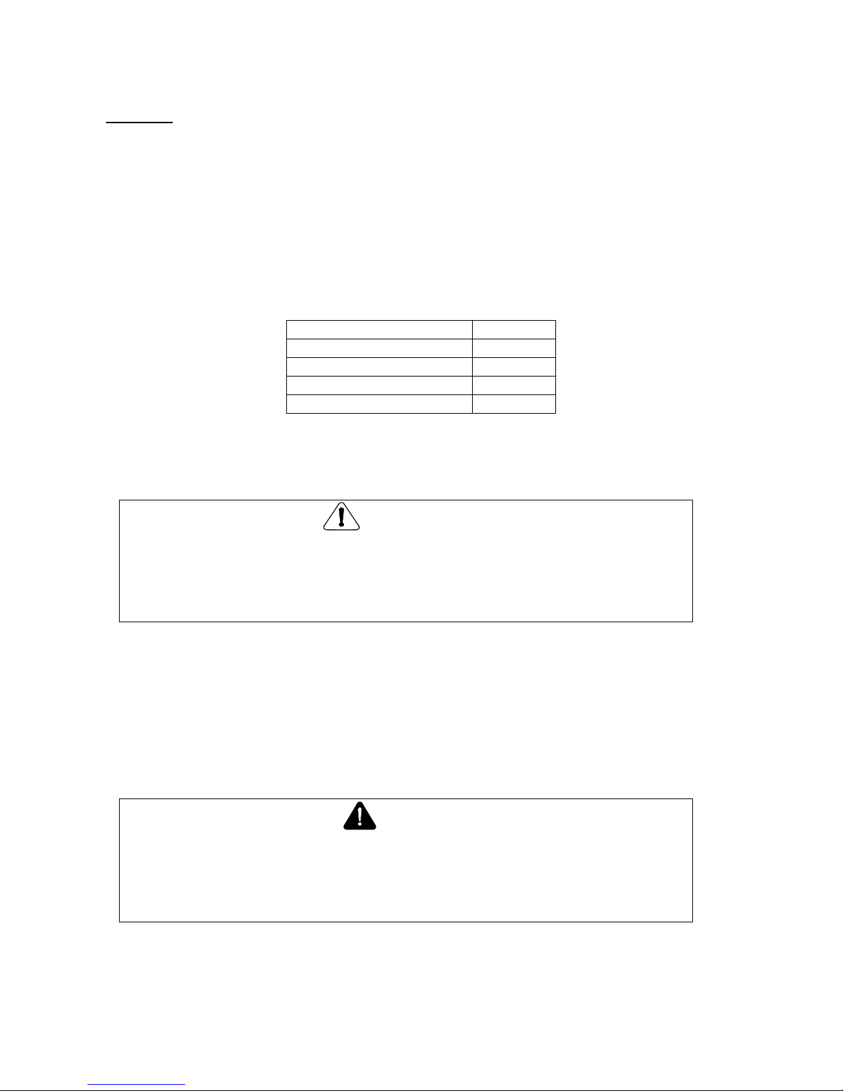
Temperature of operation has the most significant effect on the life of the lubricant. The following
chart shows the decrease in interval based on temperature.
Discharge Temperature
FSC8000
Up to 180oF
8000 hrs
180 to 190oF
6000 hrs
190 to 200oF
4000 hrs
200 to 210oF
2000 hrs
To eliminate confusion concerning what type of lubricant to use, always use CurtisLubePlus FSC- 8000
Lubricants. If other lubricants are used, failures due to lubrication are not warrantable.
CAUTION
Plugged filters, coolers, and orifices can result from mixing different lubricants and
conditioners. This will also void the warranty.
Be sure to always use CurtisLubePlus FSC- 8000 in refilling your compressor.
Oil Analysis
Oil analysis is an excellent tool to add to your compressor maintenance program. At regular intervals,
submit lubricant samples to a qualified laboratory for analysis. You should receive a detailed report
showing the lubricant condition, wear metals, and contaminants. The rate that these measurements
change over time provides the basis for predictive compressor maintenance, saving you from unplanned
machine downtime and unnecessary oil changes. Order part number VO701-POL oil sample kit.
DANGER
Hot oil under pressure will cause severe injury, death, or property damage.
Be sure the compressor is shutdown and pressure relieved before attempting to
remove the oil filter, separator, filling oil, or changing the oil.
Page 36

CAP881
36
Checking Oil Level and Adding Compressor Oil
1. Turn off the unit; disconnect the power, and lockout and tagout to prevent accidental restarting.
2. Allow one minute after stopping the compressor for settling and the pressure to relieve.
3. Remove any dirt from around the fill cap, and then remove the fill cap.
4. Inspect the cap for damage and cleanliness. Replace if necessary.
5. The oil should be visible in the window by the oil fill port on the side of the airend.
6. Replace the cap securely. Never put the cap on without tightening it immediately.
Changing Compressor Lubricant
1. Turn off the unit; disconnect the power, and lockout and tagout to prevent accidental restarting.
2. Allow one minute after stopping the compressor for settling and the pressure to relieve.
3. Remove any dirt from around the fill cap, and then remove the fill cap. If the lubricant appears
dirty or has a foul smell it should be replaced.
4. Drain the lubricant from the bottom of the oil receiver using both ball valves. Oil will drain more
quickly and completely if it is warm from operation.
5. Close all drains and replace with fresh compressor oil to the proper level.
6. Replace the fill cap and run the unit.
7. Switch off the unit and disconnect the power to prevent accidental restarting.
8. Allow one minute after stopping the compressor for settling and the pressure to relieve.
9. Remove the fill cap to see if more lubricant should be added and to insure that there are no leaks.
6.7 Thermostatic Valve
The thermostatic valve is a non-adjustable temperature control valve. On the compressor we use this
valve to mix hot and cold oil. It will begin to open at 150-155oF and be fully open at 170oF. This
insures that the system temperature is above the pressure condensation point and there is minimal
accumulation of water.
6.8 Minimum Pressure Valve
The minimum pressure valve is a non-adjustable spring biased check valve. It has been designed to
maintain a minimum sump pressure of 65 psig. If the pressure is allowed to get too low, the oil
carryover rate will increase and the separator could be damaged.
Air exiting the vent hole in the cap of the valve indicates an o-ring failure and it needs to be replaced.
The air leaking into the spring cavity where the vent is located will change the operation of the valve.
6.9 Belts
Routine examination of the drive system is recommended to insure maximum compressor life. The
belts need to be checked for wear and stretch.
To check the belts:
Turn off the unit; disconnect the power, and lockout and tagout to prevent accidental restarting.
Allow one minute after stopping the compressor for settling and the pressure to relieve.
Remove the belt guard.
Inspect for any fraying or cracking of the belts and replace if present.
Page 37
CAP881
37
Check the tension. The deflection should be about 1/64” per inch of span between the sheaves with
about 4 pounds of force perpendicular to the belt.
To change the belts: (SEG-5 thru SEG-15)
1. Turn off the unit; disconnect the power, and lockout and tagout to prevent accidental restarting.
2. Allow one minute after stopping the compressor for settling and the pressure to relieve.
3. Remove the belt guard.
4. Release tension by loosening the 2 tension bolts for the pulley.
5. Remove belts
6. Install new belts.
7. Tighten the 2 tensioning bolts and reset the tension on the belts.
6.10 Sheave Alignment
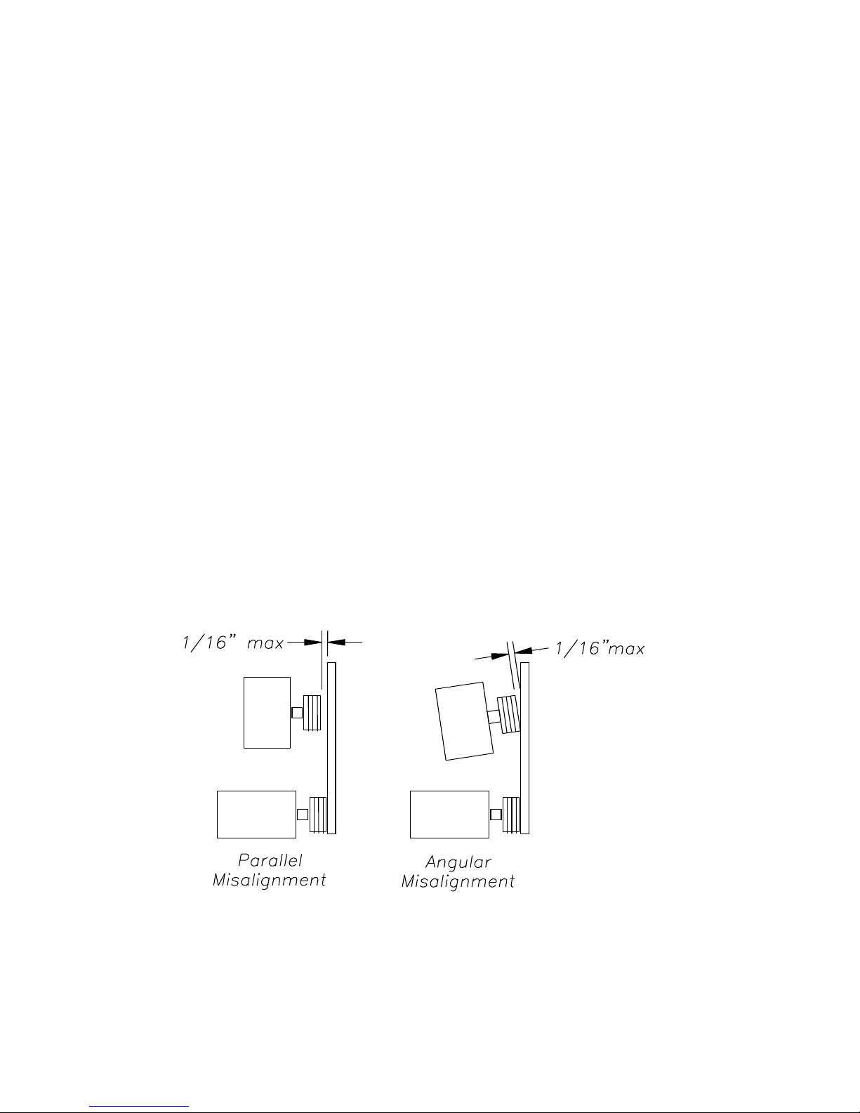
Any degree of sheave misalignment will result in a reduction of belt life. Misalignment whether parallel
or angular should not exceed 1/16”.
Parallel misalignment occurs when the shafts are parallel, but the face of the sheave is not in alignment.
Angular misalignment occurs when the shafts are not parallel.
An easy and effective method for checking the alignment in both directions is to use an accurate straight
edge.
1. Turn off the unit; disconnect the power, and lockout and tagout to prevent accidental restarting.
2. Allow one minute after stopping the compressor for settling and the pressure to relieve.
3. Remove the belt guard.
4. Lay the straight edge across the face of the motor sheave and check the alignment with the air end
sheave.
5. Then lay the straight edge across the face of the air end sheave and check the alignment with the motor
sheave.
6. If the alignment gap is greater than 1/16” in either direction, loosen the belts as outlined in changing
belts section and align the sheaves.
7. Reset the tension on the belts
Page 38
CAP881
38
CAUTION
Over greasing is a major cause of bearing and motor failure.
Make sure not to over grease or to introduce any contaminants during
greasing.
8. Return the unit to operation.
6.11 Fan
Check the fan mounted to the main motor shaft for cracking, bent or loose blades. Make sure that it is
securely mounted and tighten the mounting screws if loose. Replace a damaged fan immediately.
6.12 Motor
The motor in the air compressor requires routine maintenance. Every 1000 hours of operation or six
months, whichever comes first, check that the motor is clean and ventilation openings are clear.
The second area to maintain to insure long motor life is bearing lubrication. Bearing grease will lose its
lubricating ability over time, not suddenly. The type of grease used the temperature of operation, and
the speed of the motor effect the life of the bearing lubrication. You should re-grease the bearings
every 2000 hrs or once a year. Units in severe duty (dusty locations or high ambient temperatures) the
time interval is 1000 hours.
A high quality ball or roller bearing grease with the following characteristics should be used:
Standard Service
Hi-Temperature Service
Soap Type
Lithium
Lithium
Grease Viscosity
SSU at 100oF
400 – 550
475 – 525
Worked Penetration
265 – 296
220 – 240
N-H Bomb min hrs for 20
psi drop at 210oF
750
1000
Bleeding, max weight % in
500 hrs at 212oF
10
3
Rust Inhibiting
Yes
Yes
WARNING
Rotating machinery can cause injury or death. Open main disconnect,
tagout and lockout power supply to the starter before working on the
electric motor
Page 39

CAP881
39
Greasing the bearings:
Turn off the unit; disconnect the power, and lockout and tagout to prevent accidental restarting.
1. Clean grease fittings.
2. Remove the relief plug and free the hole of hardened grease.
3. Add grease with hand operated grease gun until it appears at the shaft hole in the end plate or the
relief plug outlet.
4. Re-connect the power, and run the unit for 20 minutes without the relief plug in place.
5. Switch off the unit; disconnect the power, and lockout and tagout to prevent accidental restarting.
6. Re-install the grease relief plug.
7. Return unit to service.
6.13 AIR END/MOTOR REMOVAL
Air end/motor removal and installation
(Note: It is important to have clear access to the air end/motor area)
Lifting devices are necessary for the removal and installation of the air end/motor
A) Turn off compressor.
B) Turn off main power and lock out and tagout to avoid accidental start-up.
C) Remove all side access panels.
D) Remove belt guard and belts from pulleys.
E) Remove 3 hose fittings from the airend which are coming from the cooler.
F) Remove 3 sensors (2-Pressure sensors & 1-Temperature sensor).
G) Unplug PD (Position Differential) switch.
H) Unplug solenoid coil from airend.
I) Remove 4 air end mounting bolts.
J) Remove air end
Installation of the air end
Reverse removal instructions and readjust belt tension before installing the belt guard screen.
Motor Removal
K) Remove cover from motor junction box.
L) Note wire connections.
M) Remove wires and conduit connectors from the motor junction box.
N) Remove 4 bolts from motor base studs.
O) Lift and remove motor from cabinet.
To reinstall motor and air end, start with step (O) and reverse procedure.
Page 40

CAP881
40
7.0 Troubleshooting
Compressor will not start
a. No power
b. Fuses blown in the control circuit.
c. Loose or missing wires or components in
the control circuit.
d. Incorrect voltage e.g. using 230 volt in a
460 volt system.
e. Faulty temperature sensor.
f. Pressure in oil separator tank.
Unit starts – but shuts down immediately
a. Pressure transducer or timer failure.
b. High Air Temperature
c. Loose or missing electrical components.
d. Pressure limit set too low.
e. Motor overloads trip out.
f. Low voltage.
Compressor does not build up to the desired
pressure.
a. Inlet valve partially closed.
b. Belt slippage.
c. Restricted inlet air cleaner.
d. Excessive air demand.
e. Defective pressure gauge.
f. Pressure limit set too low.
g. Excessive pressure drop across the separator
element.
h. Solenoid valve stuck open.
i. Air end malfunction – excessive clearance
or rotor movement.
j. Compressor sized too small.
k. Safety valve keeps discharging.
Page 41

CAP881
41
Compressor will not load
a. Pressure set too low
b. Inlet valve will not open.
c. Faulty solenoid valve.
Capacity (delivery) is below stated amount
a. Restricted inlet air filter.
b. Inlet valve partially closed.
c. Air pressure set too high.
d. Insufficient oil flow.
e. Solenoid valve malfunction.
f. Belt slippage.
g. Leakage in air system.
h. Worn air end.
Compressor surges
a. Erratic air demand.
b. Customer air system too small for supply.
c. Minimum pressure valve.
d. Pressure differential too low for the system
conditions.
e. Loose electrical connection between the
controller and the solenoid valve.
f. Faulty pressure transducer.
g. Faulty solenoid valve.
h. Faulty pressure relief valve.
Excessive Oil Consumption
a. Overfilled sump.
b. Broken oil line.
c. Plugged oil return line.
d. Operating below rated pressure.
e. Damaged or dirty separator.
f. Lightly loaded or excessive load/unload
cycles.
g. Using incorrect oil.
Page 42

CAP881
42
High Temperature Shutdown
a. Elevated ambient temperature.
b. Low sump oil level.
c. Plugged oil filter.
d. Restricted cooling airflow.
e. Clogged heat exchanger.
f. Thermal bypass is leaking
g. Faulty high air temperature sensor.
h. Delivery pressure set too high.
i. Panels are open.
j. Exhaust air is restricted.
High power consumption
a. Plugged separator.
b. Plugged aftercooler.
c. Improper air pressure switch setting.
d. Too low of a line voltage.
e. Electrical phase imbalance.
f. Imminent motor failure.
g. Imminent air end failure
h. Belt slippage
i. Loose electrical connection
Safety valve discharges
a. Over pressure not set correctly.
b. Inlet valve not closing properly in relation to
air demand.
c. Plugged separator.
d. Faulty minimum pressure check valve.
e. Faulty safety valve.
Page 43

CAP881
43
8.0 Maintenance Log
Model: _____________________ Serial Number: _____________________
Date
Hourmeter
Reading
Changed
Greased
Motor
Bearings
Cleaned
Cooler
Checked
Fitting
Tightness
Air
Filter
Oil
Filter
Oil
Separator
Page 44

CAP881
44
NOTES
 Loading...