

FScurtis CA series, ES03, ES05, ES06, ES10 Installation And Operating Instruction Manual
...
CAP600AE
NOVEMBER, 2008
AIR COMPRESSOR
INSTALLATION AND
OPERATING INSTRUCTION
MANUAL
Before installing and operating this compressor, read
and understand the safety precautions contained in
LV-474 supplement to and part of CAP-600
IMPORTANT
Make a permanent record of the
Model and Serial number of
your machine here. You’ll save
time and expense by including
this reference identification on
replacement part orders.
*CONSULT FACTORY FOR SPECIAL APPLICATIONS
WARNING
CURTIS-TOLEDO, INC.
1905 Kienlen Avenue
St. Louis, MO 63133
REFER TO MODEL & SERIAL NUMBER.
READ INSTAL. & OPERATION INSTR.
DO NOT OPERATE LOW ER THAN 500
R.P.M. OR ABOVE MAX. AS STIPULATED
BY PERFORMANCE DATA SHEET.
SERIAL NO.MODEL NO.
CURTIS-TOLEDO, INC.
1905 Kienlen Avenue, St. Louis, Missouri 63133
phone: 314-383-1300 fax: 314-381-1439
email:info@curtistoledo.com website: www.fscurtis.com
Sales representatives in principal cities

CAP-600
INSTALLATION
CONGRATULATIONS on your new Curtis
Challenge Air Compressor. Please examine the
compressor for shipping damage(s) and if any are
found report it immediately to the carrier.
Select a clean dry location with a rigid floor strong
enough to support the compressor. If the
compressor is to be located in an area where
vibration is critical, properly engineered vibration
mounts and flexible piping should be used.
Remove the skid. NOTE: The compressor should
never be operated on the shipping skid. Level
the compressor so it can be bolted down securely.
Before tightening the bolts, check to see that all
four feet are resting on the foundation. Shim as
necessary to eliminate stress on the receiver or
base when the bolts are tightened. We suggest
using a level for proper alignment.
Maximum ambient temperature in which the
compressor and motor should be operated is
104°F. Therefore, adequate ventilation must be
provided.
The suction openings of the compressor are
equipped with a combination air filter-muffler to
protect the compressor from normal dust and other
harmful substances. If the air around the
compressor is excessively hot, dusty, humid or
contaminated with foreign gases (such as ammonia
or acid fumes) move the filter-muffler to a remote
point where the air is clean, cool and dry. Run a
pipe to the compressor suction opening. If the run
is over 50 feet in length, use a larger pipe to avoid
excessive pressure drop. In order to fit the filter to
the compressor, bush down the connections. Be
sure piping and fittings are clean and free from dirt
and chips. If the filter is installed outside, check to
insure that it is located above the normal outside
dust level, and that rain cannot enter the filter
element. Where the relocation of the filter-muffler
is not possible or feasible, an oil bath filter is
recommended and is available from Curtis.
LIMITED SAFETY PRECAUTIONS
(Also see supplement LV-474)
The following safety precautions are recommended
in the use of this compressor:
1. Use a totally enclosed OSHA-approved belt
guard to cover the drive assembly. Where
possible, place the flywheel toward the wall, and
mount the unit a minimum distance of 2 feet from
the wall for maintenance convenience.
2. Turn off & lock out the electrical disconnect
switch before working on the unit to prevent the
unit from starting unexpectedly
WARNING: Read and understand supplement LV-474 before installing and operating the compressor.
On basic or base mounted compressors run a
discharge pipe to the receiver or optional
aftercooler and bush up or down as necessary.
The pipe should enter near the top of the receiver.
Keep in mind that condensate may form in the
discharge line; therefore, the lines should always
be pitched to drain condensate away from the
compressor. Always provide a safety relief valve in
the discharge line between the compressor and inline shutoff valves. If more than one compressor
pumps into a common system, a check valve in the
discharge line of each compressor is recommended
to prevent moisture from entering the cylinder head
when one compressor is idle. A globe or gate valve
installed in the discharge line will allow compressor
isolation from plant air system for compressor
maintenance. (Note: A safety relief valve should be
located between the compressor and the
globe/gate valve.)
Check the electrical supply for voltage, phase, and
frequency to see that they match the nameplate
stampings on the motor, magnetic starter,
solenoids, and other controls. Use electrical wires
of adequate size to carry the full load current of the
motor without excessive voltage drop. Charts are
available from Curtis (upon request) to provide
information on this. The motor must always be
protected by a starter with properly sized thermal
overload(s). The starter should protect the motor
from overheating and burnout due to an overload,
low voltage or single phasing of a 3-phase circuit.
Failure to install the proper starter and
overloads will void the motor manufacturers
warranty. Follow the National Electric Code or
local electric code in providing wiring, fusing and
disconnect switches. NOTE: Do not close the
disconnect switch to start the compressor until
the procedures outlined under "Startup
Procedures" have been completed.
3. Release all air pressure from the system before
working on the unit and red tag all electrical
control switches, for safety precaution.
4. Do not by-pass motor over-current protection.
5. Do not change the setting or in any way affect
the operation of the safety valve.
6. Keep unit securely anchored so that movement
will not put a strain on piping, wiring, or air
receiver.
2
START-UP PROCEDURES
OIL RECOMMENDATION
Use Genuine CURTISLUBEPLUS Lubricants. Specially
formulated for Curtis Reciprocating Air Compressors. NonDetergent type with anti-foam, anti-rust and oxidation inhibitors.
Recommended ISO68 RC-1000 Premium Reciprocating
Compressor Lubricant, Part no. VO411-3, 12-quart case or
VO411-2, 4 gallon case.
Recommended ISO100 RC-1000A Premium Reciprocating
Compressor Lubricant Part no. VO421-3, 12-quart case or
VO421-2, 4 gallon case.
CURTISLUBEPLUS Lubricants are available through your
authorized Curtis distributor.
CAP-600
If the compressor is equipped with an automatic start-stop
control (with pressure switch unloading), it is automatically
unloaded upon starting, and will automatically load after
attaining running speed. If the compressor is equipped with
a constant speed control (pilot valve unloading), it is
necessary to manually unload the compressor, if there is
pressure in the discharge line, in order to achieve an
unloaded start. The compressor must be manually loaded
after the compressor has attained full running speed, there
after, it functions automatically to maintain operating
pressure until the unit is shut off.
Close the disconnect switch and start the compressor.
Observe the direction of rotation, which should be
counterclockwise when viewed from the flywheel side of the
compressor on all models. For single-phase units, the
direction of rotation is determined by the motor nameplate
instructions, and is adjusted at the factory. For three-phase
units, if the rotation is incorrect, stop the unit and
interchange any two of the three wires to the motor at the
disconnect switch. This will reverse the direction of rotation
of the motor and compressor.
PREVENTIVE MAINTENANCE
A good maintenance program will add years of service to your air
compressor. The following is recommended as a minimum
maintenance program. (TURN OFF POWER BEFORE
SERVICING.)
LUBRICATION
1. For proper lubrication the compressor shall not be
operated below the minimum or above the maximum R. P.M.
recommended for the various models.
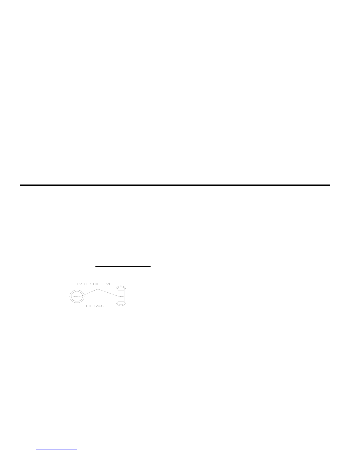
2. Maintain oil level mid-way between the upper and lower lines
of the crankcase sight gage.
3. Stop compressor to add and gauge oil.
4. Do not fill above the upper line and do not operate compressor
with oil level below the lower line.
DO NOT OVER FILL
5. Change oil at the first 100 hours of operation and 1000 hours
thereafter, or as required. It may be necessary to change oil
more frequent due to abnormal humid and contaminated
conditions.
DAILY MAINTENANCE
1. Check and maintain oil level at centerline of sight glass and
add oil as necessary.
2. Drain condensate from receiver unless it is equipped with an
automatic tank drain, in which case the drain should be
checked weekly to see that it is operating. See automatic tank
drain instructions.
NOTE ILLUSTRATION:
WARNING: Read and understand supplement LV-474 before installing and operating the compressor.
3. Check for unusual noise or vibration (See "Trouble Shooting".)
WEEKLY MAINTENANCE
1. Clean the air filters. A clogged air filter can seriously affect the
efficiency of the compressor and cause overheating and oil
usage.
2. Clean all external parts of the compressor and driver. Be sure
to clean the intercooler-finned surface on two-stage
compressors. A dirty compressor will cause abnormally high
discharge temperature and resulting oil carbonization on
internal valve components
3. Check the safety valve manually (by pulling ring or lever) to
see that it is not stuck.
MONTHLY MAINTENANCE
1. Inspect the entire air system for leaks.
2. lnspect condition of oil and change if necessary.
3. Check drive belt tension and tighten if needed.
EVERY 3 MOS. OR 1,000 HRS. OF OPERATION
1. Change oil.
2. lnspect valves. Clean the carbon from valves and head if
necessary.
3. Check and tighten if necessary all bolts, nuts, etc.
4. Check unloader operation.
*CHECKING BELT TENSION
The v-belt(s) should be adjusted so that a declination of about 3/8
– 1/2 inch will be obtained when it is pushed by a finger at the
middle point as shown in Figure 1.
CAUTION: Over tightening the v-belt(s) will result in
overloading of the motor and belt failure, while a loose belt
will be slipping and resulting in an unstable speed,
overheating the belt and high amp draw.
3
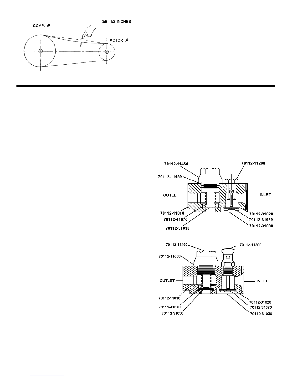
Figure 1
VALVE INSPECTION AND MAINTENANCE
Valves should be inspected at regular intervals as
recommended under "Maintenance" and cleaned or
replaced when necessary. The valve can be serviced
without disconnecting air piping or removing the head.
(Be sure the power to the motor is disconnected and
all pressure released before starting to work on the
compressor.)
On constant run models, it is necessary to remove the
unloader piping before the valve plugs can be removed.
MODELS E-11 AND E-23 (Figures 2 and 3)
A. Disassembly:
1. Unbolt the outlet valve push cover (70112- 11450).
2. Remove the outlet valve push cover packing (70112-
11650), spring (70112-41070) and valve plate (70112-
31030). CAUTION: Steps 1 and 2 are for outlet
valve.
3. Remove the unloading connecting tube for Models
E-11 and E-23.
4. Untighten four cylinder head fixed bolts.
5. Remove cylinder head carefully and turn it over.
6. Unbolt inlet valve receiver (70112-31020).
7. Remove valve spring (70112-31070) and valve plate
(70112-31030).
Valves should be inspected approximately every 1,000
hours of operation. Inspect the valve seats on
cylinder head for dents, cracks or wear. Replace all
defective parts. Remove carbon deposits and wash all
valve components in a suitable non-flammable
cleaning fluid.
B. Assembly:
1. Place outlet valve plate (70112-31030) in position.
2. Place the outlet valve push cover packing (70112-
11650) in position.
3. Insert the spring (70112-41070) into outlet valve push
cover (70112-11450).
4. Turn outlet valve push cover (70112-11450) in position
carefully.
CAP-600
To change tension, loosen the motor hold-down bolts and
slide the motor on the base, using a lever if necessary, or
by turning the adjusting bolt at the end of the base.
Retighten motor hold-down bolts.
NOTE: Do not over tighten belts.
ELECTRIC MOTOR
Grease once a year with a good grade of lithium ball
bearing grease, or as directed by the motor manufacturer.
5. Check the valves to see if they can move freely in their
guides.
6. Turn over the cylinder head (70112-11010).
7. Place the inlet valve plate (70112-31030) in position.
8. Insert the small end of inlet valve spring (70112-
31070) into position of valve receiver (70112- 31020).
9. Screw inlet valve receiver in position.
10. Check the valves to see if they can move freely in their
guides and do not pinch or bind between the seat and
guard legs.
Figure 2
WARNING: Read and understand supplement LV-474 before installing and operating the compressor.
Figure 3
4
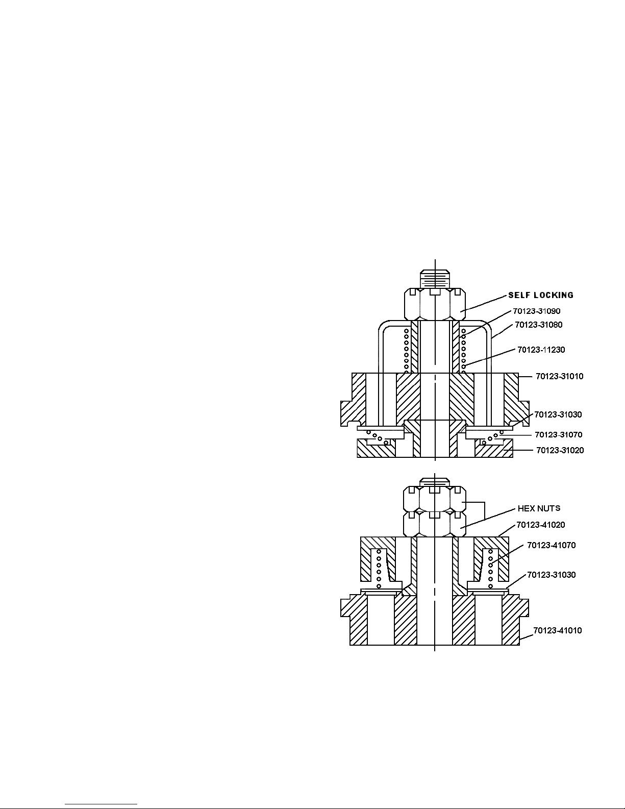
MODELS E-50, E-71 AND E-15 (Figures 4 and 5)
A. Disassembly of Inlet Valve Assembly (Figure 4).
1. Untighten the hex nut.
2. Remove unloading fork (70123-31080), unloading fork
guide (70123-31090), unloading spring (70123-11230)
and valve seat (70123-31010).
CAUTION:
1. If a vise is used to hold the valve assembly, be
careful not to clamp the assembly too tight.
2. Valve assembly should be inspected approximately
every 1,000 hours of operation.
3. Inspect the valve seat for dents, cracks or wear.
4. Replace all defective parts.
5. Valve seats that might be worn after years of
operation can be re-lapped or re-ground, in this
case the recess in which the valve guard legs fit
must also be cut down accordingly to ensure a
same valve lift.
6. Remove carbon deposits and wash all valve
components in a suitable non-flammable cleaning
fluid.
B. Reassembly of Inlet Valve Assembly
1. Place valve spring (70123-31070) and valve plate
(70123-31030) on valve receiver (70123-31020).
2. Place valve seat (70123-31010), unloading fork guide
70123-31090), unloading spring (70123- 11230) and
unloading fork (70123-31080) respectively.
3. Tighten the valve assembly by tightening the hex nut.
4. Check the valves to see if they can move freely in their
guides and do not pinch or bind between the seat and
guard legs.
C. Disassembly of Outlet Valve Assembly (Figure 5)
1. Untighten the hex nuts.
2. Remove valve receiver (70123-41020), valve spring
(70123-41070) and valve plate (70123-31030).
CAUTION: Refer to disassembly of inlet valve assembly
(paragraph B).
CAP-600
D. Reassembly of Outlet Valve Assembly
1. Place valve spring (70123-41070) in valve receiver
70123-41020).
2. Place valve plate (70123-31030) in valve receiver.
(70123-41020).
3. Insert the sub-assembled part (assembled in
step I and 2) into valve seat (70123-41010).
4. Tighten the hex nuts.
5. Check the valves to see if they can move freely in their
guides and do not pinch or bind between the seat and
guard legs.
FIGURE 4 (EXAMPLE SHOWN E-50)
WARNING: Read and understand supplement LV-474 before installing and operating the compressor.
FIGURE 5
5
(EXAMPLE SHOWN E-50)
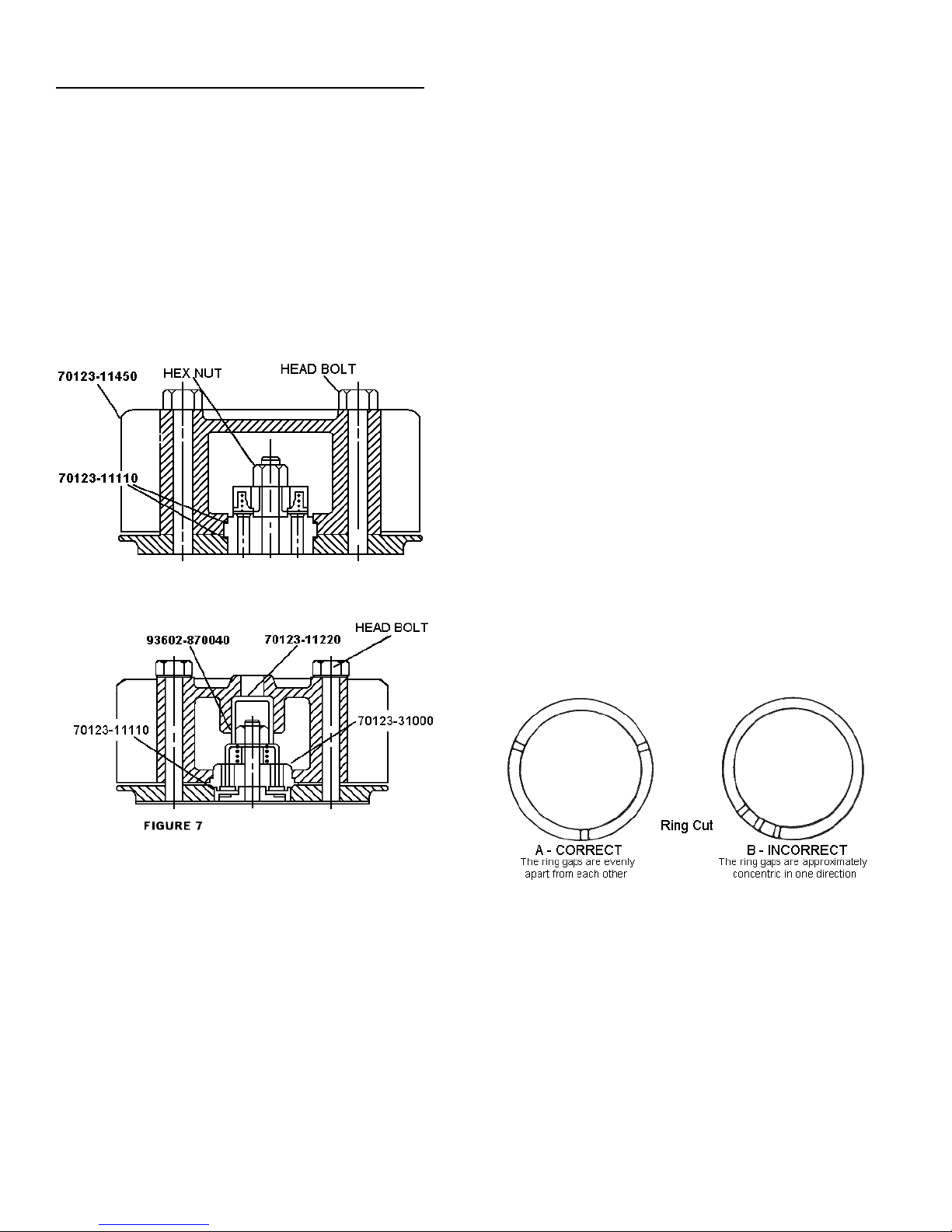
VALVE ASSEMBLY INSTALLATION - E-50 MODEL
(Figures 6 and 7)
1. Install valve assembly gasket (70123-11110)
2. Install valve assembly (70123-31000).
3. Install valve push cover (70123-11150).
4. Install head bolt and tighten evenly and securely.
It is strongly recommended that a Preventative
Maintenance Kit & Valve/Gasket Maintenance Kit be kept
on hand. In this manner, the valves can be used in turn to
keep the compressor always in good condition and a
minimum downtime.
FIGURE 6
CAP-600
PISTON RINGS (Rebuild Kit)
To inspect or replace piston rings as follows:
1. Remove cylinder head.
2. Remove cylinder.
3. Loosen the connecting rod bolts.
4. Push out the piston with piston rings and connecting
rod.
5. To remove the old rings, pry them out of their grooves
and slide them over the piston. Care should be taken
not to damage the piston.
6. Inspect the ring grooves for nicks and carbon deposits.
Clean the ring grooves and remove the obstructions,
which might prevent the rings from moving freely.
To install new rings on the piston as follows: (Be
careful not to damage the piston and rings).
1. Install the oil control ring (70123-61050) first. Rotate
ring in groove to make sure it is free.
2. Install the Compression ring (70123-61030). Make sure
the "top" or "R" mark is exactly on top. If not, it might
cause excessive oil consumption.
3. Repeat the process with other rings, if any.
4. Assemble connecting rod into the crankshaft. Be sure
that the connecting rod and its cap are in original pair
and position, since the connecting rod cap and
crankshaft pin bushing are selected fitted and are not
interchangeable.
5. Check if the ring gaps are in proper positions (Figure 8).
FIGURE 8
WARNING: Read and understand supplement LV-474 before installing and operating the compressor.
6
CAP-600
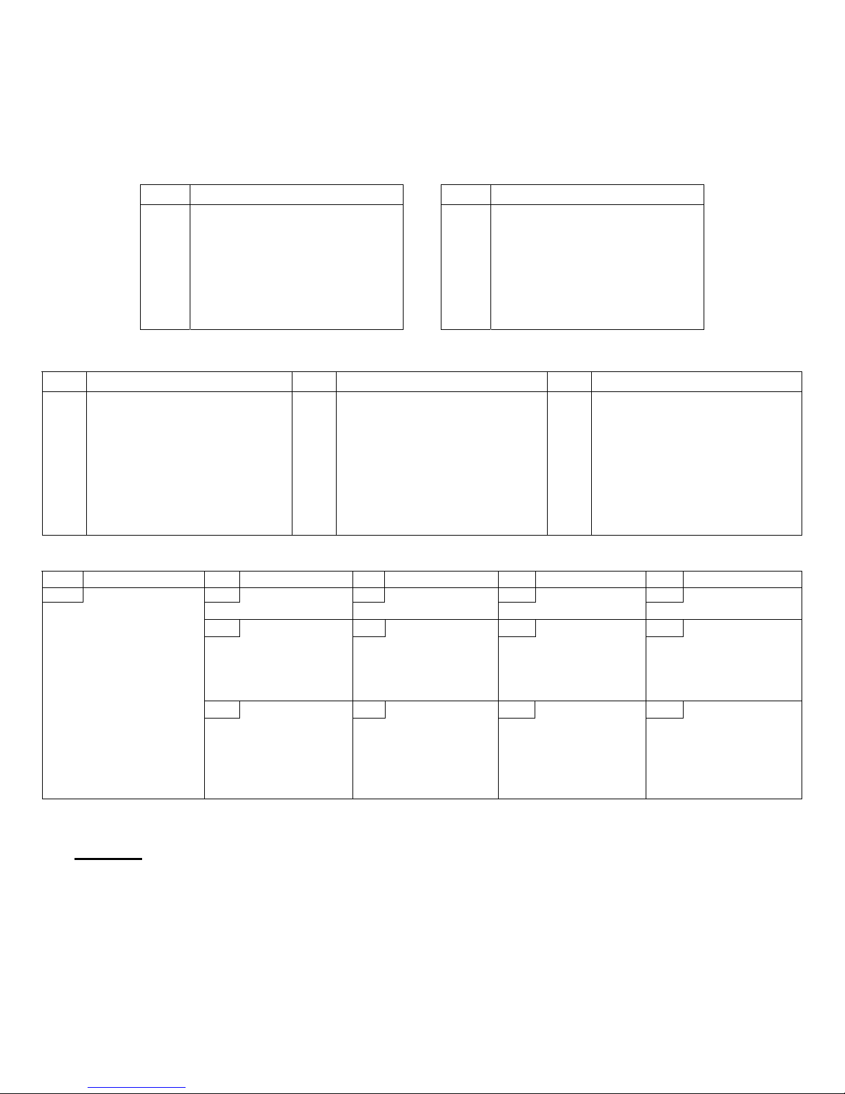
• REBUILD KITS
AIR COOLED SINGLE STAGE MODELS
PART
NO.
CF1237
1 70112-11461 Copper Gasket
ES05
CONSISTS OF:
PART
NO.
CF1299
ES03
CONSISTS OF:
1 70111-66140 Filter Element 1 70111-66140 Filter Element
2 70111-31030 Valve Disc 2 70112-31030 Valve Disc
1 70111-31070 Spring 1 70112-31070 Spring
1 70111-41070 Spring 1 70112-41070 Spring
1 70111-11461 Gasket 2 70112-61030 Comp. Ring
1 70111-11612 Head Gasket 1 70112-61050 Oil Ring
2 70111-61030 Comp. Ring 1 70112-11612 Head Gasket
1 70111-61050 Oil Ring 1 70112-51610 Crankcase Gasket
1 70111-57970 Bottom Cover Gasket 1 70112-57950 Front Cover Gasket
1 70111-57950 Front bearing cover gasket 1 70112-57960 Rear Cover Gasket
1 70111-57080 Front Oil Seal 1 70112-57080 Oil Seal
1 70111-57960 Rear Cover Gasket 12 92521-190800 Copper Washer
10 92521-190600 Copper Washer
ES06 ES10, ES10P ES20
PART
NO.
CF1302
CONSISTS OF:
2 70111-66140 Filter Element 2 70111-66140 Filter Element 3 70111-66140 Filter Element
4 70111-31030 Valve Disc 4 70112-31030 Disc 6 70112-31030 Disc
2 70111-31070 Spring 2 70112-31070 Spring 3 70112-31070 Spring
2 70111-41070 Spring 2 70112-41070 Spring 3 70112-41070 Spring
2 70111-11461 Gasket 4 70112-61030 Compression Ring 6 70112-61030 Compression Ring
2 70111-11612 Head Gasket 2 70112-61050 Oil Ring 3 70112-61050 Oil Ring
2 70121-51610 Crankcase Gasket 2 70112-11612 Head Gasket 3 70112-11612 Head Gasket
4 70111-61030 Comp. Ring 2 70112-51610 Crankcase Gasket 3 70112-51610 Crankcase Gasket
2 70111-61050 Oil Ring 1 70122-57950 Front Cover Gasket 1 70122-57950 Front Cover Gasket
1 70121-57950 Front Cover Gasket 1 70122-57960 Rear Cover Gasket 1 70122-57960 Rear Cover Gasket
1 70111-57960 Rear Cover Gasket 1 70122-57080 Front Oil Seal 1 70122-57080 Front Oil Seal
1 70121-57970 Bottom Cover Gasket 24 92521-190800 Copper Washer 26 92521-190800 Copper Washer
24 92521-190600 Copper Washer 2 70112-11461 Copper Gasket 3 70112-11461 Copper Gasket
PART
NO.
CF1238
CONSISTS OF:
PART
NO.
CF1239
CONSISTS OF:
PART
NO.
CF1246 REBUILD KIT INCLUDES:
2 70123-66140 Filter Kit
4 70123-31030 Disc
2 70123-31070 Spring
2 70123-41070 Spring
4 70123-61030 Compression Ring
4 70123-61050 Oil Ring 6 70123-31030 Disc 6 70124-31030 Disc 6 70125-31030 Disc 3 70125-31030 Disc I / V
4 70123-11110 Seat Gasket 3 70123-31070 Spring 3 70124-31070 Spring 3 70125-31070 Spring 3 70125-31070 Spring
2 70123-11612 Head Gasket 3 70123-41070 Spring 3 70124-41070 Spring 9 70125-41074 Spring 9 701212A1-41075 Spring
2 70123-51610 Crankcase Gasket 6 70123-11110 Seat Gasket 6 70124-11110 Seat Gasket 6 70125-11110 Seat Gasket 6 70125-11110 Seat Gasket
1 70123-57950 Front Cover Gasket 3 70123-11612 Head Gasket 3 70124-11612 Head Gasket 3 70125-87510 Manifold Gasket 3 70125-41030 Disc O / V
1 70123-57960-01 Rear Cover Gasket 3 70125-11610 Head Gasket 3 70125-11612 Head Gasket
1 70123-57080 Front Oil Seal ** 70125-11612 Head Gasket
*2 70123-61081 Bushing
2 70123-61090 Set, Rod Bearing
26 92521-191000 Copper Washer
1 70123-57080 Front Oil Seal 1 70124-57950
6 70123-61030 Compr.Ring 6 70124-61030 Compr.Ring 6 70125-61030 Compression Ring 6 70125-61030 Compression Ring
6 70123-61050 Oil Ring 6 70124-61050 Oil Ring 6 70125-61050 Oil Ring 6 70125-61050 Oil Ring
*3 70123-61081 Bushing 3 70124-61080 Bushing *3 70125-61081 Bushing *3 70125-61081 Bushing
3 70123-61090 Set, Rod Bearing 6 70124-61090 Set, Rod Bearing 3 70125-61090 Set, Bearing 6 70125-61090 Set, Bearing
3 70123-51610 Crankcase Gasket 3 70124-51610 Crankcase Gasket *3 70135-51610 Crankcase Gasket *3 70135-51610 Crankcase Gasket
1 70123-57950
1 70133-57960
ES-30 ES-50 ES-100 ES-150 ES-150A
CONSISTS OF:
PART
NO.
CF1252
3 70123-66140 Filter Element 3 70123-66140 Filter Element 3 70123-66140 Filter Element 3 70123-66140 Filter Element
CF1245
CF1244 REBUILD KIT INCLUDES: CF1242 REBUILD KIT INCLUDES: CF1244 REBUILD KIT INCLUDES: CF1244 REBUILD KIT INCLUDES:
34
CONSISTS OF:
PREVENTATIVE MAINTENANCE
KIT INCLUDES
VALVE / GASKET MAINT. KIT INCLUDES
92521-191000
Frt. Brg. Cvr. Gasket
Rear Brg. Cvr. Gasket
Copper Washer
PART
NO.
CF1252
CF1243
1 70134-57080 Front Oil Seal 1 70135-57950 Frt. Brg.Cvr Gasket 1 70135-57950 Frt. Brg.Cvr Gasket
1 70134-57960
34
CONSISTS OF:
PREVENTATIVE MAINTENANCE
KIT INCLUDES
VALVE / GASKET MAINT. KIT INCLUDES:
Frt. Brg. Cvr. Gasket
92521-191000
Rear Brg. Cvr. Gasket
Copper Washer
PART
NO.
CF1252
CF1241
1 70134-57080 Front Oil Seal 1 70134-57080 Front Oil Seal
1 70134-57960 Rear Brg.Cvr Gasket 1 70134-57960 Rear Brg.Cvr Gasket
24 92521-191000 Copper Washer 24 92521-191000 Copper Washer
CONSISTS OF:
PREVENTATIVE MAINTENANCE
KIT INCLUDES
VALVE / GASKET MAINT. KIT INCLUDES:
PART
NO.
PREVENTATIVE MAINTENANCE
CF1252
KIT INCLUDES
VALVE / GASKET MAINT. KIT INCLUDES:
CF1320
CONSISTS OF:
* WARNING – THESE ITEMS INTERCHANGE WITH PARTS ON SERIAL #3020000 & HIGHER ONLY.
CONTACT FACTORY FOR EARLIER SERIES.
** USE WITH SERIAL #A311XXXX AND LATER
70135-11610 REPLACES 70125-11610
.
7

CAP-600
• REBUILD KITS
AIR COOLED TWO STAGE MODELS
E-11 E-23
PART
NO.
CF1250 1 70111-66140 Filter Element CF1251 2 70111-66140 Filter Element
2 70112-31030 Disc 4 70112-31030 Disc
2 70162-32030 Disc 2 70111-31030 Disc
1 70112-31070 Spring 2 70112-31070 Spring
1 70162-42070 Spring 2 70112-41070 Spring
1 70112-41070 Spring 1 70172-32070 Spring
1 70162-32070 Spring 1 70172-42070 Spring
2 70112-61030 Compression Ring 4 70112-61030 Compression Ring
1 70112-61050 Oil Ring 2 70112-61050 Oil Ring
2 70162-62030 Compression Ring 2 70111-61030 Compression Ring
2 70162-62050 Oil Ring 2 70111-61050 Oil Ring
1 70112-11612 Head Gasket (1st) 2 70112-11612 Head Gasket (1st)
1 70162-12610 Head Gasket (2nd) 1 70111-11612 Head Gasket (2nd)
2 70112-51610 Crankcase Gasket 3 70112-51610 Crankcase Gasket
1 70122-57950 Front Cover Gasket 1 70122-57950 Front Cover Gasket
1 70122-57960 Rear Cover Gasket 1 70122-57960 Rear Cover Gasket
1 70122-57080 Front Oil Seal 1 70122-57080 Front Oil Seal
24 92521-190800 Copper Washer 32 92521-190800 Copper Washer
1 70112-11461 Copper Gasket 1 70111-11461 Copper Gasket
2 70112-11461 Copper Gasket
CONSISTS OF:
PART
NO.
CONSISTS OF:
PART
NO.
CF1306
1 70152-66141 Element
CF1307
4 70152-31030 Disc
2 70152-32030 Disc
4 70152-31070 Spring
2 70152-32070 Spring
1 70152-11612 Head Gasket
1 70152-31120 Seat Gasket
1 70152-11622 Seat Gasket
CF1308 REBUILD KIT INCLUDES:
1 70152-51610 Case Gasket
1 70152-57960 Rear Cover Gasket
2 70152-61030 Comp. Ring
1 70152-61050 Oil Ring
1 70152-61080 Bushing (L.P.)
1 70152-62080 Bushing (H.P.)
2 70152-61090 Rod Bearing Set
3 70152-62030 Compression Ring
1 70152-62050 Oil Ring
1 70152-57950 Front Cover Gasket
1 70127-57080 Front Oil Seal
6 92521-190800 Copper Washer
E-35
CONSISTS OF:
PREVENTATIVE MAINTENANCE
KIT INCLUDES:
VALVE/GASKET MAINT KIT
INCLUDES:
E-57 E-50 E-71 E-15
PART NO. CONSISTS OF:
CF1291
CF1292
CF1293 REBUILD KIT INCLUDES: CF1254 REBUILD KIT INCLUDES: CF1256 REBUILD KIT INCLUDES: CF1258 REBUILD KIT INCLUDES:
26 92521-191000 Copper Washer 34 92521-191000 Copper Washer 34 92521-191000 Copper Washer 1 93503-NK28/30 Needle Bearing ***
PREVENTATIVE MAINTENANCE KIT
1 70153-66142 Element 2 70123-66140 Element 2 70123-66140 Element 2 70123-66140 Element
4 70153-31032 Disc 6 70123-31030 Disc 4 70124-31030 Disc 4 70125-31030 Disc
2 70153-32032 Disc 3 70123-31070 Spring 2 70123-31030 Disc 2 70175-42030 Disc
4 70153-31072 Spring 3 70123-41070 Spring 2 70124-31070 Spring 2 70125-31070 Spring
2 70153-32072 Spring 6 70123-11110 Seat Gasket 1 70123-31070 Spring 1 70124-31070 Spring
1 70153-31120 Head Gasket 3 70123-11612 Head Gasket 2 70124-41070 Spring 6 70125-41070 Spring
1 70153-11612 Seat Gasket 1 70123-41070 Spring 1 70124-41072 Spring
1 70153-11622 Seat Gasket 4 70124-11110 Seat Gasket 4 70125-11110 Seat Gasket
2 70123-11110 Seat Gasket 2 70124-11110 Seat Gasket
2 70124-11612 Head Gasket 4 70125-87510 Manifold Gasket
1 70123-11612 Head Gasket 2 70125-11610 Head Gasket
1 70124-11612 Head Gasket
** 70135-11610 Head Gasket
1 70153-57951 Front Bearing Gasket 1 70123-57950 Front Bearing Gasket 1 70124-57950 Front Bearing Gasket 4 70125-61030 Compression Ring
2 70124-61030 Compression Ring 4 70123-61030 Compression Ring 4 70124-61030 Compression Ring 4 70125-61050 Oil Ring
2 70124-61050 Oil Ring 4 70123-61050 Oil Rings 4 70124-61050 Oil Ring 3 70124-61030 Compression Ring
3 70153-62030 Compression Ring 3 70112-61030 Compression Ring 3 70123-61030 Compression Ring 2 70124-61050 Oil Ring
1 70153-62050 Oil Ring 1 70112-61050 Oil Ring 2 70123-61050 Oil Ring 2 70125-61081 Bushing
1 70153-61081 Bushing (L.P.) 2 70123-61081 Bushing 2 70124-61080 Bushing 3 70125-61090 Rod Bearing (2 Halves)
1 70153-62081 Bushing (H.P.) 1 93503TA1725 Needle Bearing 1 70174-62081 Bushing 3 70135-51610 Gasket
4 70153-61090 Rod Bearing (Halves) 6 70123-61090 Rod Bearing (Halves) 3 70124-51610 Gasket 1 70134-57080 Oil Seal
1 70153-51611 Case Gasket 3 70123-51610 Crankcase Gasket 1 70134-57080 Oil Seal 1 70135-57950 Front Bearing Gasket
1 70123-57080 Oil Seat 1 70123-57080 Oil Seal 6 70124-61090 Bearing (Halves) 1 70134-57960 Rear Bearing Gasket
1 70153-57961 Rear Bearing Gasket 1 70133-57960 Rear Bearing Gasket 1 70134-57960 Rear Bearing Gasket 24 92521-191200 Copper Washer
1 70173-62080 Bushing 1 70175-62080 Bushing ****
INCLUDES
VALVE/GASKET MAINT KIT
INCLUDES:
PART
NO.
CF1315
CF1253
CONSISTS OF:
PREVENTATIVE MAINTENANCE
KIT INCLUDES:
VALVE/GASKET MAINT KIT
INCLUDES:
PART
NO.
CF1315
CF1255
CONSISTS OF:
PREVENTATIVE MAINTENANCE
KIT INCLUDES:
VALVE/GASKET MAINT KIT
INCLUDES:
PART
NO.
CF1315
CF1257
CONSISTS OF:
PREVENTATIVE MAINTENANCE
KIT INCLUDES:
VALVE/GASKET MAINT KIT
INCLUDES:
* WARNING – THESE ITEMS INTERCHANGE WITH PARTS ON SERIAL #3020000 & HIGHER ONLY.
CONTACT FACTORY FOR EARLIER SERIES.
** USE WITH SERIAL #A311XXXX AND LATER
70135-11610 REPLACES 70125-11610
*** USE WITH SERIAL #A409XXXX AND LATER
**** USE FOR UNITS PRIOR TO SERIAL #A409XXXX
.
8

CAP-600
RING SETS & GASKET SETS
SINGLE STAGE
QUANTITY
MODEL PART NO. DESCRIPTION
ES03
ES05
ES06
ES10
ES20
ES30
ES50
ES100
ES150 &
ES150A
CF1297
CF1298
CF1259
CF1276
CF1300
CF1301
CF1260
CF1277
CF1261
CF1278
CF1262
CF1279
CF1263
CF1280
CF1264
CF1281
CF1265
CF1282
*CF1311
Ring set
Gasket set
Ring set
Gasket set
Ring set
Gasket set
Ring set
Gasket set
Ring set
Gasket set
Ring set
Gasket set
Ring set
Gasket set
Ring set
Gasket set
Ring set
Gasket set
*Gasket set
REQ’D
1
1
1
1
2
1
2
1
3
1
2
1
3
1
3
1
3
1
1
TWO-STAGE
MODEL PART NO. DESCRIPTION
CF1266
E11
E23
E35
E50
E57
E71
E15
* USE WITH SERIAL #A311XXXX AND LATER
CF1267
CF1283
CF1268
CF1269
CF1284
CF1303
CF1304
CF1305
CF1270
CF1271
CF1285
CF1288
CF1289
CF1290
CF1272
CF1273
CF1286
CF1274
CF1275
CF1287
*CF1313
Ring set (LP)
Ring set (HP)
Gasket set
Ring set (LP)
Ring set (HP)
Gasket set
Ring set(LP)
Ring set(HP)
Gasket set
Ring set(LP)
Ring set(HP)
Gasket set
Ring set(LP)
Ring set(HP)
Gasket set
Ring set(LP)
Ring set(HP)
Gasket set
Ring set(LP)
Ring set(HP)
Gasket set
*Gasket set
QUANTITY
REQ’D
1
1
1
2
1
1
1
1
1
2
1
1
1
1
1
2
1
1
2
1
1
1
9

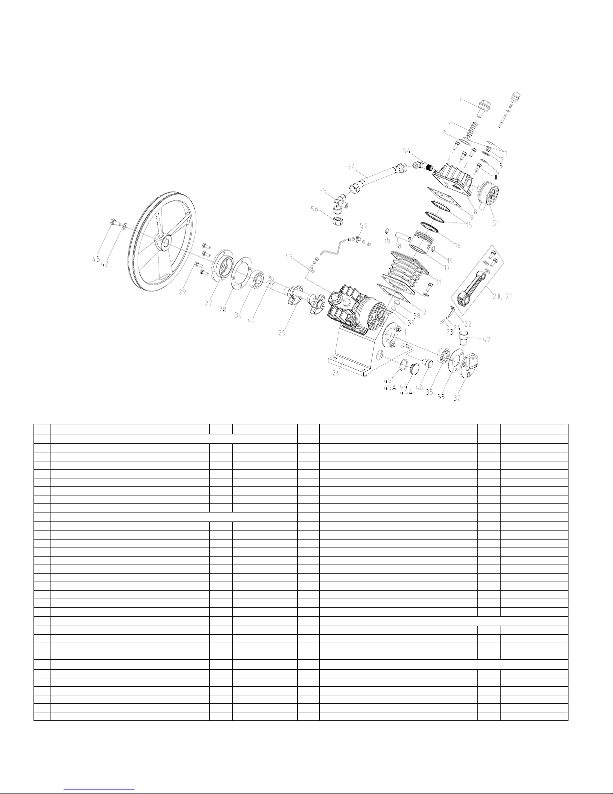
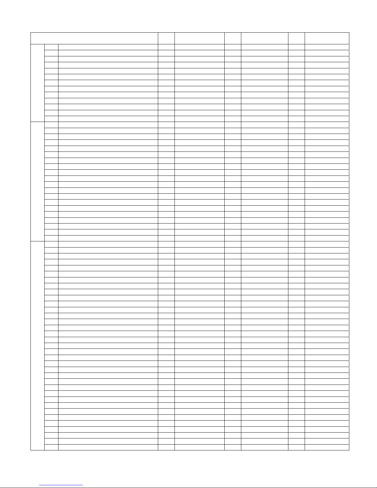
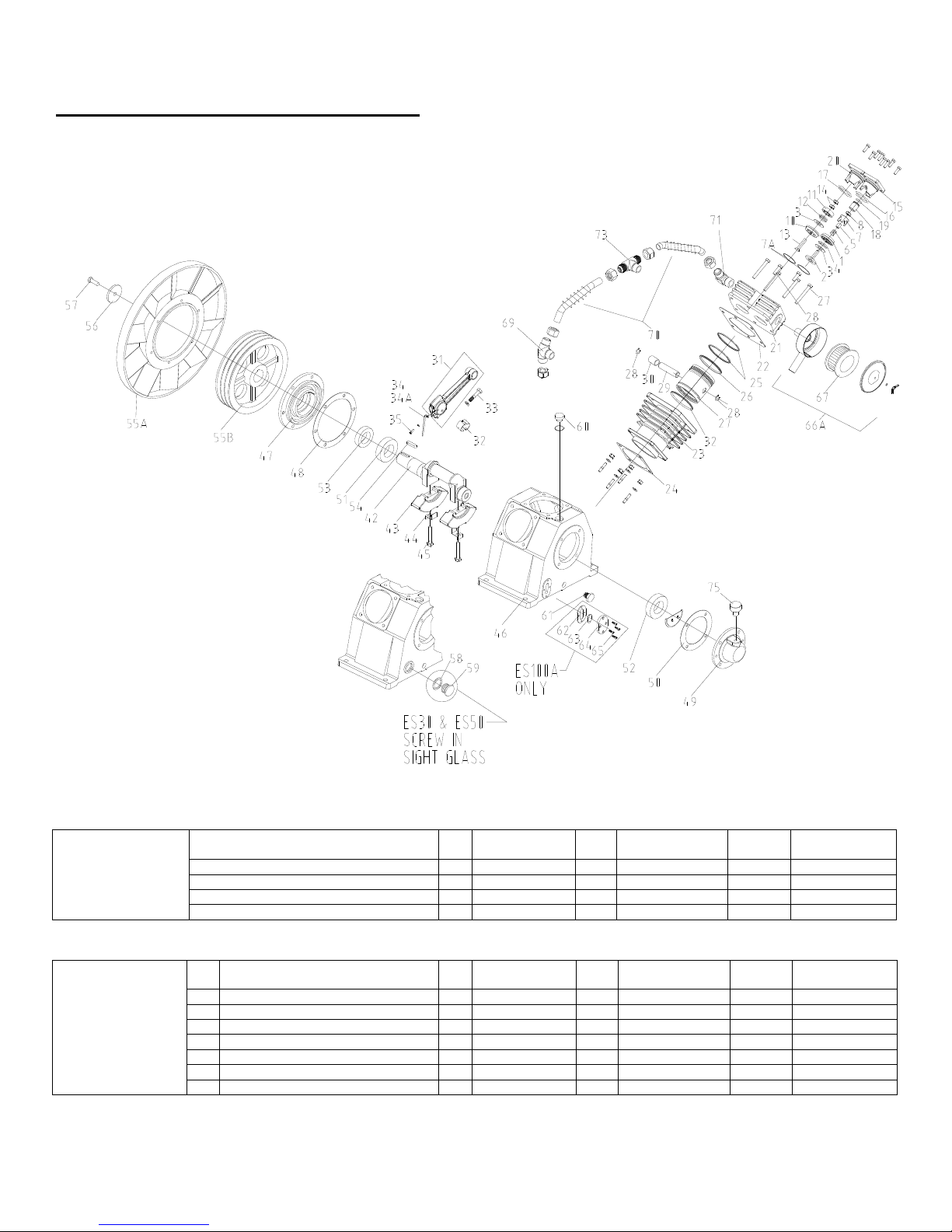
MODEL ES-03
AIR COOLED, SINGLE STAGE, SINGLE CYLINDER
CAP-600
Description QTY PART NO.
VALVES
1. Inlet & Outlet Valve Plate 2 70111-31030
2. Inlet Valve Spring 1 70111-31070
3. Inlet Valve Receiver 1 70111-31020
4. Inlet Valve Snap Ring 1 93610-130225
5. Outlet Valve Spring 1 70111-41070
6. Outlet Valve Push Cover Gasket 1 70111-11461
7. Outlet Valve Push Cover 1 70111-11450
8. Manual Unloader Assembly 1 70111-11300
9.
CYLINDERS
9A. Cylinder Head Assembly (Includes Valves) 1 70111-11000-4024
9B. Cylinder Head (Bare Casting) 1 70111-11010
10. Cylinder Head Bolt (Not Shown) 4 (Hardware Item)
11. Cylinder Head Gasket 1 70111-11612
12. Cylinder & Crankcase 1 70111-57010-4024
13. Compression Ring 2 70111-61030
14. Oil Control Ring 1 70111-61050
15. Piston 1 70111-61011
16. Piston Pin 1 70111-61120
17. Piston Pin Snap Ring 2 70111-61070
18. Connecting Rod Assembly 1 70111-61200
19. Connecting Rod Bolt 2
20. Oil Splash Dipper 1 70111-61282
21. Oil Splash Dipper Bolt 1 91507-2304010
22. Oil Splash Dipper Bolt Washer (Not Shown) 1 92522-130400
CRANKCASE AND CRANK ASSEMBLY
(furnished on conn.
Rod only)
23. Crankshaft 1 70111-56010
24. Front Bearing Cover 1 70111-57030
25. Front Bearing Cover Gasket 1 70111-57950
26. Front Cover Bolts (Not Shown) 4 91501-1306016
27. Front Bearing #6203 1 93501-6203
28. Rear Bearing Cover 1 70111-57060
29. Rear Bearing Cover Gasket 1 70111-57960
30. Rear Bearing #6201 1 93501-6201
31. Rear Bearing Cover Bolts (Not Shown) 3 93501-1306016
32. Front Oil Seal 1 70111-57080
33. Compressor Pulley 1 70111-76010
34. Compressor Pulley Thrust Washer 1 70111-76210
35. Compressor Pulley Thrust Bolt 1 91501-1306020
36. Crankcase Bottom Cover (Not Shown) 1 70111-57220
37.
38. Compressor Pulley Pin NA (Not Required)
39. Oil Level Gauge And Cover 1 70111-57700
40. Gauge Cover Seal 1 70111-57730
41. Crankcase Oil Plug (1/4” PT) 1 90112-100202
42. Breather Assembly 1 70191-57600-4024
AIR STRAINER ELEMENT
43. Air Strainer Assembly 1 70111-66001
44. Air Strainer Element (Not Shown) 1 70111-66140
10
Description QTY PART NO.
CRANKCASE AND CRANK ASSEMBLY
Crankcase Bottom Cover Gasket (Not
Shown)
1 70111-57970
MODEL ES-06
AIR COOLED, SINGLE STAGE, TWO CYLINDER
CAP-600
DESCRIPTION QTY PART NO. DESCRIPTION QTY PART NO.
VALVES
1. Inlet And Outlet Valve Plate 4 70111-31030 29 Front Bearing Cover Bolt 4 91501-1306016
2. Inlet Valve Spring 2 70111-31070 30 Front Bearing #6204 1 93501-6204
3. Inlet Valve Receiver 2 70111-31020 32 Rear Bearing Cover 1 70111-57060
4. Inlet Valve Snap Ring 2 93610-130225 33 Rear Bearing Cover Gasket 1 70111-57960
5. Outlet Valve Spring 2 70111-41070 34 Rear Bearing Cover Bolt (Not Shown) 3 91501-1306016
6. Outlet Valve Push Cover Gasket 2 70111-11461 35 Rear Bearing #6203 1 93501-6203
7. Outlet Valve Push Cover 2 70111-11450 36 Crankcase Bottom Cover (Not Shown) 1 70121-57220
37 Crankcase Bottom Cover Bolt (Not Shown) 1 70121-57970
CYLINDERS, CRANKCASE AND CRANK ASSEMBLY
8a. Cylinder Head Assy. (Includes Valves) 2 70111-11000-4024 39 Front & Rear Cover Bolt Washer (Not Shown) 10 92521-190600
8b. Cylinder Head (Bare Casting) 2 70111-11010 40 Compressor Pulley Pin 1 70112-56060
9. Cylinder Head Gasket 2 70111-11612 41 Compressor Pulley 1 70121-76011
10 Cylinder Head Bolt 8 91501-1306055 42 Compressor Pulley Thrust Washer 1 70112-76210
11 Cylinder 2 70121-51010 43 Compressor Pulley Thrust Bolt 1 91501-1306025
12 Cylinder To Case Gasket 2 70121-51610 44 Oil Level Gauge & Gauge Cover 1 70111-57700
13 Cylinder To Case Bolt (Not Shown) 8 91501-1306016 *44A Oil Level Gauge Assy 1 70704-57700
14 Cylinder To Case Bolt Washer (Not Shown) 16 92521-190600 45 Oil Level Gauge Cover Seal 1 70111-57730
15 Compression Ring 4 70111-61030 *45A Oil Level Gauge “O” Ring 1 93602-8126026
16 Oil Control Ring 2 70111-61050 46 Crankcase Oil Plug (1/4” NPT) 1 90112-100202
17 Piston 2 70111-61011 47 Breather Assembly 1 CCC1357
18 Piston Pin 2 70111-61120
19 Piston Pin Snap Ring 4 70111-61070 48 Auto – Unloader Assembly 2 70112-11201
20 Connecting Rod Assembly 2 70111-61200 49 Unloading Elbow* (Includes Nut & Sleeve) 1 VA786
21 Connecting Rod Bolt 4
22 Oil Splash Dipper 2 70121-61282
23 Oil Splash Dipper Bolt 2 91507-2304010 51 Air Strainer Assembly 2 70111-66001
24 Oil Splash Dipper Lock washer 2 92522-130400 52 Air Strainer Element (Not Shown) 2 70111-66140
25 Crankshaft 1 70121-56010 53 Compressor Body Discharge Pipe Assembly 1 70121-87100
26 Crankcase 1 70121-57010-4024 54 Outlet Pipe Elbow 1 70121-87010
27 Front Bearing Cover 1 70121-57030 55 Outlet Pipe Tee 1 70121-87020
56 Outlet Pipe Tee Nut 1 79922-130404
(Furnished On
Conn, Rod Only)
* START S/N AS 4030001
28 Front Bearing Cover Gasket 1 70121-57950
38 Crankcase Bottom Cover Washer (Not Shown) 4 (Hardware Item)
UNLOADERS(* Indicates Not Included On Basic Units)
50 Unloading Tee* (Includes Nut & Sleeve) 1 VA787
AIR STRAINER ASSEMBLY & DISCHARGE PIPING
11

AIR COOLED, SINGLE STAGE MODELS
ES-05, ES-10 & ES-20
CAP-600
12

CAP-600
MAIN PARTS LISTING FOR
SINGLE STAGE MODELS
ES-05, ES-10 & ES-20
VALVES
1. Inlet And Outlet Valve Plate 2 70112-31030 4 70112-31030 6 70112-31030
2. Inlet Valve Spring 1 70112-31070 2 70112-31070 3 70112-31070
3. Inlet Valve Receiver 1 70112-31020 2 70112-31020 3 70112-31020
4. Inlet Valve Snap Ring 1 93610-130232 2 93610-130232 3 93610-130232
5. Outlet Valve Spring 1 70112-41070 2 70112-41070 3 70112-41070
6. Outlet Valve Push Cover Gasket 1 70112-11461 2 70112-11461 3 70112-11461
7. Outlet Valve Push Cover 1 70112-11450 2 70112-11450 3 70112-11450
CYLINDER AND CYLINDER HEADS
16A. Cylinder Head Assembly 1
16B. Cylinder Head 1 70112-11010 2 70112-11010 3 70112-11010
17. Cylinder & Head Gasket 1 70112-11612 2 70112-11612 3 70112-11612
18. Cylinder 1 70112-51010 2 70112-51010 3 70112-51010
19. Cylinder And Case Gasket 1 70112-51610 2 70112-51610 3 70112-51610
20. Compression Ring 2 70112-61030 4 70112-61030 6 70112-61030
21. Oil Control Ring 1 70112-61050 2 70112-61050 3 70112-61050
22. Piston 1 70112-61011 2 70112-61011 3 70112-61011
23. Piston Pin 1 70112-61120 2 70112-61120 3 70112-61120
24. Piston Pin Snap Ring 2 70112-61070 4 70112-61070 6 70112-61070
25. Connecting Rod Assembly 1 70112-61200-1 2 70112-61200-1 3 70112-61200-1
26. Connecting Rod Bolt 1 70112-61250 4 70112-61250 6 70112-61250
27. Oil Splash Dipper 1 70111-61282 2 70122-61282 2 70122-61282
27A. Oil Splash Dipper 1 70132-61290
28. Oil Splash Dipper Bolts 1 91507-2304010 2 91507-2304010 3 91507-2304010
29. Cylinder Head Bolt 4 (Hardware Item) 8 (Hardware Item) 12 (Hardware Item)
CRANK ASSEMBLY
39. Crankcase 1
40. Crankshaft 1 70112-56010 1 70122-56010 1 70132-56010
41. Front Bearing Cover 1 70112-57030 1 70122-57030 1 70122-57030
42. Front Bearing Cover Gasket 1 70112-57950 1 70122-57950 1 70122-57950
43. Rear Bearing Cover 1 70112-57060 1 70122-57060 1 70122-57060
44. Rear Bearing Cover Gasket 1 70112-57960 1 70122-57960 1 70122-57960
45A. Bearing – Front 1 93501-6205 1 93501-6205 1 93501-6205
45B. Bearing – Rear 1 93501-6204 1 93501-6204 1 93501-6204
46. Front Oil Seal 1 70112-57080 1 70122-57080 1 70122-57080
47. V-Pulley Pin 1 70112-56060 1 70112-56060 1 70112-56060
48. Compressor Pulley 1 70112-76010 1 70122-76011 1 70122-76011
49. Compressor Pulley Thrust Washer 1 70112-76210 1 70112-76210 1 70112-76210
50. Compressor Pulley Thrust Bolt 1 91501-1308025 1 91501-1308025 1 91501-1308025
51. Breather Assembly 1
52. Oil Gauge & Gauge Cover 1 70111-57700 1 70111-57700 1 70111-57700
٭52 A Oil Level Gauge Assembly - 1 70704-57700 1 70704-57700
53. Gauge Cover Seal 1 70111-57730 1 70111-57730 1 70111-57730
٭53 A Oil Level Gauge “O” Ring - 1 93602-8126026 1 93602-8126026
54. Crankcase Oil Plug 1 90112-100202 1 90112-100202 1 90112-100202
54A. Oil fill cap - - 1
54B. “O” Ring - - 1 93601-810016
UNLOADERS
55. Auto – Unloader Assembly 1 70112-11201
56. Auto – Unloader Spring 1 70112-11230 2 70112-11230 3 70112-11230
57. Auto – Unloader Piston 1 70112-11221 2 70112-11221 3 70112-11221
58. O-Ring (Unloader) 1 93601-810004 2 93601-810004 3 93601-810004
AIR STRAINER
61. Air Strainer Element (not shown) 1 70111-66140
62. Air Strainer Assembly 1 70111-66001 2 70111-66001 3 70111-66001
63. Discharge Piping Assembly 1 (Not Required) 2 70122-87100 2 70132-87100
64. Outlet Pipe Joint A - 1 70122-87010 1 70122-87010
65. Outlet Pipe Joint B - 1 70122-87020 1 70132-87020
66. Outlet Pipe Joint C - - 1 70132-87030
QTY
REQ’D
MODEL ES05
70112-11000-4024
70112-57010-4024
CCC1375
• ES10, START S/N AS 4030043
• ES20, START S/N AS 4030061
QTY
REQ’D
2
1
1
2 70112-11201
2 70111-66140
MODEL ES10
70112-11000-4024
70122-57010-4024
CCC1375
QTY
REQ’D
3
1
1
3 70112-11201
3 70111-66140
MODEL ES20
70112-11000-4024
70132-57010-4024
CCC1375
70101-57190-4010
13

AIR COOLED SINGLE STAGE
t
t
MODELS ES-30, ES-50, ES-100
CAP-600
VALVE ASSEMBLIES
VALVE &
UNLOADERS
Description
Inlet Valve Assembly, 1
Outlet Valve Assembly, 1
Breather Assembly 1
s
Stage 2 70123-31000 3 70123-31000 3 70124-31000
s
Stage 2 70123-41000 3 70123-41000 3 70124-41000
Qty.
Req.
MODEL
ES30
70103-57600-4024
Qty.
Req.
70103-57600-4024
1
MODEL
ES50
Qty.
Req.
MODEL
ES100
1 70124-57600
MAIN PARTS LISTING FOR MODELS
ES-30, ES-50, ES-100
Item
Description
No.
1. Inlet Valve Seat 2 70123-31010 3 70123-31010 3 70124-31010
2. Inlet Valve Receiver 2 70123-31020 3 70123-31020 3 70124-31020
3. Inlet & Outlet Valve Plate 4 70123-31030 6 70123-31030 6 70124-31030
4. Inlet Valve Spring 2 70123-31070 3 70123-31070 3 70124-31070
5. Inlet Valve Unloading Fork Guide 2 70123-31090 3 70123-31090 3 70124-31090
6. Unloading Spring 2 70123-11230 3 70123-11230 3 70124-11230
7A. Valve Gasket 4 70123-11110 6 70123-11110 6 70124-11110
Qty.
Req.
MODEL
ES30
Qty.
Req.
MODEL
ES50
Qty.
Req.
MODEL
ES100
14
CAP-600
t
t
t
t
t
t
t
t
t
t
t
t
MAIN PARTS LISTING FOR MODELS
ES-30, ES-50 & ES-100 (Continued)
Qty.
Req.
7B Inlet Valve Unloading Fork 2 70123-31080 3 70123-31080 3 70124-31080
8. Locknut 2 92518-230800 3 92518-230800 3 92518-230800
10. Outlet Valve Seat 2 70123-41011 3 70123-41011 3 70124-41011
11. Outlet Valve Receiver 2 70123-41020 3 70123-41020 3 70124-41020
12. Outlet Valve Spring 2 70123-41070 3 70123-41070 3 70124-41070
13. Outlet Valve Bolt 2 70123-41810 3 70123-41810 3 70124-41810
14. Nut (Outlet Valve) 4 92502-130800 6 92502-130800 6 92502-130800
15. Inlet Valve Push Cover, 1
(Cont’d)
16. O – Ring G 40 2 93602-810040 3 93602-810040 3 93602-810055
17. Viton O – Ring G 40 (Outlet Valve) 2 93602-870040 3 93602-870040 3 93602-870055
18. Unloading Piston, 1
VALVES & UNLOADERS
19. O – Ring P 20 2 93601-810020 3 93601-810020 3 93601-810021
20. Outlet Valve Push Cover, 1
21A. Cylinder Head Assembly 2 70123-11000 3 70123-11000 -
21. Cylinder Head (1
22. Cylinder & Head Gasket, 1
23. Cylinder (1
s
s
) 2 70123-51012 3 70123-51012 3 70124-51011
s
Stage 2 70123-11150 3 70123-11150 3 70124-11150
s
Stage 2 70123-11220 3 70123-11220 3 70124-11220
s
Stage 2 70123-11450 3 70123-11450 3 70124-11450
) 2 70123-11010 3 70123-11010 3 70124-11010
s
Stage 2 70123-11612 3 70123-11612 3 70124-11612
23A. S/N 3020000 THRU A311XXXX 2 70123-51011 3 70123-51011 3 70124-51011
24. Cylinder & Case Gasket 2 70123-51610 3 70123-51610 3 70124-51610
25. Compression Ring (1
26. Oil Control Ring (1
27. Piston (1
s
) 2 70123-61011 3 70123-61011 3 70124-61011-1
s
) 4 70123-61030 6 70123-61030 6 70124-61030
s
) 4 70123-61050 6 70123-61050 6 70124-61050
27A. S/N 3020000 & later use 2 70123-61011 3 70123-61011 3 70124-61011
28. Piston Pin Snap Ring 4 70123-61070 6 70123-61070 6 70124-61070
29. Piston Pin (1
CYLINDERS
30. Connecting Rod Piston Pin Bushing (1
31. Connecting Rod Assembly, 1
s
) 2 70123-61120 3 70123-61120 3 70124-61120
s
s
) 2 70123-61081 3 70123-61081 3 70124-61080
Stage 2 70123-61200 3 70123-61200 3 70124-61201
31A. S/N 3020000 & later use 2 70123-61201 3 70123-61201 3 70124-61201
32. Connecting Rod Crank Pin Metal 4 70123-61090 6 70123-61090 6 70124-61090
33. Connecting Rod Bolt 4 70123-61250 6 70123-61250 6 70125-61250
34A. Oil Splash Dipper H.P. - 1 70122-61290 1 70134-62290
34. Oil Splash Dipper 2 70122-61282 2 70122-61282 2 70134-61281
35. Oil Splash Dipper Bolt 2 91507-2304012 3 91507-2304012 3 91507-2305016
42. Crankshaft 1 70123-56010 1 70133-56011 1 70134-56010
43. Counterweight - - 2 70134-56030
44. Lockwasher - - 2 70124-56830
45. Bolt - - 2 70124-56810
46. Crankcase 1 70123-57010-4024 1 70133-57010-4024 1 70134-57010-4024
47. Front Bearing Cover 1 70123-57030 1 70133-57030 1 70134-57031
48. Front Bearing Cover Gasket 1 70123-57950 1 70123-57950 1 70124-57950
49. Rear Bearing Cover 1 70123-57061 1 70133-57060 1 70134-57061
49A. S/N 3020000 & later use 1 70123-57061 1 70133-57061 1 70134-57061
50. Rear Bearing Cover Gasket 1 70123-57960-01 1 70133-57960 1 70134-57960
51. Front Bearing 1 93501-6206 1 93501-6206 1 93502-32210
52. Rear Bearing 1 93501-6206 1 93501-6206 1 93502-32210
53. Front Oil Seal 1 70123-57080 1 70123-57080 1 70134-57080
54. V – Pulley Pin 1 70123-56061 1 70123-56061 1 70134-56060
55A. Compressor Fan 1 (Not Required) 1 (Not Required) 1 70124-76310
55B. Compressor Pulley 1 70123-76010 1 70133-76010 1 70134-76011
56. Compressor Pulley Washer 1 70123-76210 1 70124-76210 1 70124-76210
57. Compressor Pulley Set Bolt 1 91501-1312030 1 91501-1312030 1 91501-1312040
58. O-Ring (oil level glass) 1 93602-81260-3065 1 93602-81260-3065 - -
59. Screw in Oil Level Glass 1 70A109B1-57702 1 70A109B1-57702 - -
60. Crankcase Oil Cap 1 CCC1257 1 CCC1257 1 CCC1257
61. Crankcase Oil Plug 1 90112-100404 1 90112-100404 1 90112-100404
62. Oil Level Glass Gasket 1 701210A1-57730 1 701210A1-57730 1 701210A1-57730
63. Oil Level Glass Assy. 1 701210A1-57700 1 701210A1-57700 1 701210A1-57700
CRANKCASE & CRANK ASSEMBLY
64. Oil Level Glass, Push Cover 1 701210A1-57740 1 701210A1-57740 1 701210A1-57740
65. Screw, Metric Pan Head 4 VH1470 4 VH1470 4 VH1470
66A Air Strainer Assembly 2 70123-66000 3 70123-66000 3 70123-66000
67. Air Strainer Filter 2 70123-66140 3 70123-66140 3 70123-66140
69. Outlet Pipe Joint B 1 70123-87020 1 70133-87020 1 70134-87020
70. Compressor Body Discharge Piping Assy. 1 70123-87100 2 70133-87101 2 70134-87100
70A. S/N 3020000 & Later Use 1 70123-87101 2 70133-87101 2 70134-87101
71. Outlet Pipe Joint A 1 70123-87010 1 70123-87010 1 70124-87010
73. Outlet Pipe Joint C - 1 70133-87030 1 70134-87030
74. Gasket (Manifold) - - -
75. Breather Assembly 1 CCC1375 1 CCC1375 1 CCC1375
MODEL
ES30
15
Qty.
Req.
MODEL
ES50
Qty.
Req.
MODEL
ES100
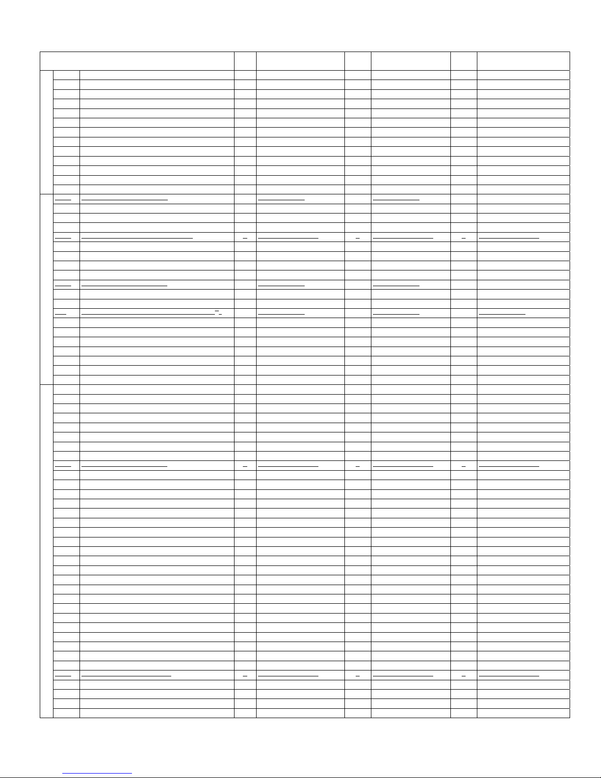
AIR COOLED SINGLE STAGE
t
t
MODELS ES-30A, ES-50A, ES-100A
CAP-600
Description
VALVE ASSEMBLIES
Inlet Valve Assembly, 1
Outlet Valve Assembly, 1
Breather Assembly 1 701105A1-57600 1 701105A1-57600 1 701210A1-57601
MAIN PARTS LISTING FOR MODELS
ES-30A, ES-50A, ES-100A
Item
Description
No.
1. Inlet Valve Seat 2 701208A1-31010 3 701208A1-31010 3 701210A1-31010
VALVE &
UNLOADERS
2. Inlet Valve Receiver 2 701208A1-31020 3 701208A1-31020 3 701210A1-31020
3. Inlet & Outlet Valve Plate 2 701208A1-31030 6 701208A1-31030 6 501210A1-31030
4. Inlet Valve Spring 2 701208A1-31070 3 701208A1-31070 3 701210A1-31070
5. Inlet Valve Unloading Fork Guide 2 701208A1-31090 3 701208A1-31090 3 701210A1-31090
6. Unloading Spring 2 701208A1-11230 3 701208A1-11230 3 701210A1-11230
7A. Valve Gasket 4 701208A1-11110 6 701208A1-11110 6 701210A1-11110
Qty.
s
Stage 2 701208A1-31000 3 701208A1-31000 3 701210A1-31000
s
Stage 2 701208A-41000 3 701208A1-41000 3 701210A1-41000
Req.
Qty.
Req.
14A
MODEL
ES30A
MODEL
ES30A
Qty.
Req.
Qty.
Req.
MODEL
ES50A
MODEL
ES50A
Qty. Req.
Qty. Req.
MODEL
ES100A
MODEL
ES100A
MAIN PARTS LISTING FOR MODELS
t
t
t
t
t
t
t
t
t
t
t
t
ES-30A, ES-50A & ES-100A (Continued)
Qty.
Req.
7B. Inlet Valve Unloading Fork 2 701208A1-31080 3 701208A1-31080 3 70210A1-31080
8. Locknut 2
10. Outlet Valve Seat 2 701208A1-41011 3 701208A1-41011 3 701210A1-41011
11. Outlet Valve Receiver 2 701208A1-41020 3 701208A1-41020 3 701210A1-41020
12. Outlet Valve Spring 2 701208A1-41070 3 701208A1-41070 3 701210A1-41070
13. Outlet Valve Bolt 2 701208A1-41810 3 701208A1-41810 3 9152613-1110050-5608
14. Nut (Outlet Valve) 4 9250113-150800-532 6
15. Inlet Valve Push Cover, 1
s
Stage 2 701208A1-11150 3 701208A1-11150 3 701210A1-11150
16. O – Ring G 40 (G55 ES100) 2 9360281-310394 3 9360281-310394 3 9360281-310544
17. Viton O – Ring G 40 (Outlet Valve) 2 9360287-310394 3 9630287-310394 3 9360287-310544
18. Unloading Piston, 1
19. O – Ring P 20 (P21 ES100) 2 9360181-240198 3 9360181-240198 3 9360187-240208
VALVES & UNLOADERS (Cont’d)
20. Outlet Valve Push Cover, 1
21A. Cylinder Head Assembly 2 70123-11000 3 70123-11000 -
21. Cylinder Head (1
22. Cylinder & Head Gasket, 1
23. Cylinder (1
s
s
Stage 2 701208A1-11220 3 701208A1-11220 3 701210A1-11220
s
Stage 2 701208A1-11450 3 701208A1-11450 3 701210A1-11450
s
) 2 701208A2-11010 3 701208A2-11010 3 701210A2-11010
s
Stage 2 701208A1-11020 3 701208A1-11020 3 701210A1-11020
) 2 701208A2-51010 3 701208A2-51010 3 701210A2-51010
23A. S/N 3020000 THRU A311XXXX 2 701208A1-51010 3 701208A2-51010 3 701210A2-51010
24. Cylinder & Case Gasket 2 701208A1-51030 3 701208A1-51030 3 701210A1-51030
25. Compression Ring (1
26. Oil Control Ring (1
27. Piston (1
s
) 2 701208A1-61012 3 701208A1-61012 3 701210A1-61011
s
) 4 701208A1-61030 6 701208A1-61030 6 701210A1-61030
s
) 4 701208A1-61050 6 701208A1-61050 6 701210A1-61050
27A. S/N 3020000 & later use 2 70123-61011 3 70123-61011 3 701210A1-61011
28. Piston Pin Snap Ring 4 701208A1-61070 6 701208A1-61070 6 701210A1-61070
29. Piston Pin (1
CYLINDERS
30. Connecting Rod Piston Pin Bushing (1
31. Connecting Rod Assembly, 1
s
) 2 701208A1-61120 3 701208A1-61120 6 701210A1-61120
s
s
) 2 70123-61081 3 70123-61081 3 70124-61080
Stage 2 701208A1-61201 3 701208A1-61201 3 701210A1-61201
31A. S/N 3020000 & later use 2 701208A1-61201 3 701208A1-61201 3 701210A1-61201
32. Connecting Rod Crank Pin Metal 4 70123-61090 6 70123-61090 6 70124-61090
33. Connecting Rod Bolt 4 70123-61250 6 70123-61250 6 70125-61250
33A. Oil Splash Dipper H.P. - 1 70130FA1-61290 1 701310A1-61290
34. Oil Splash Dipper 2 70120FA1-61282 2 70120FA1-61282 2 701310A1-61281
35. Oil Splash Dipper Bolt 2
42. Crankshaft 1 701208A1-56011 1 701308A1-56011 1 701310A1-56010
43. Counterweight - - 2 701310A1-56030
44. Lockwasher - - 2 701210A1-56830
45. Bolt - - 2 701210A1-56810
46. Crankcase 1 701208A2-57010 1 701308A2-57010 1 701310A2-57010
47. Front Bearing Cover 1 701208A1-57030 1 701308A1-57030 1 701310A1-57031
48. Front Bearing Cover Gasket 1 701208A1-57040 1 701208A1-57040 1 701210A1-57040
49. Rear Bearing Cover 1 701208A1-57061 1 701308A1-57061 1 701310A1-57061
49A. S/N 3020000 & later use 1 701208A1-57061 1 701308A1-57061 1 701310A1-57061
50. Rear Bearing Cover Gasket 1 701208A1-57070 1 701308A1-57070 1 701310A1-57070
51. Front Bearing 1 9350104-6206 1 9360112-6306 1 9354501-32210
52. Rear Bearing 1 9350104-6206 1 9360112-6306 1 9354501-32210
53. Front Oil Seal 1 701208A1-57080 1 701208A1-57080 1 701310A1-57080
54. V – Pulley Pin 1 701208A1-56061 1 701208A1-56061 1 701310A1-56060
55A. Compressor Fan 1 (Not Required) 1 (Not Required) 1 70121071-76311
55B. Compressor Pulley 1 701208A1-76010 1 701308A1-76010 1 701310A1-76011
56. Compressor Pulley Washer 1 701208A1-76210 1 70124-76210 1 701210A1-76210
57. Compressor Pulley Set Bolt 1
58. O-ring (Oil Level Glass) 1
59. Screw In Oil Level Glass 1
60. Crankcase Oil Cap 1 CCC1257 1 CCC1257 1 CCC1257
61. Crankcase Oil Plug 1 9156310-400800 1 9156310-400800 1 9156310-400800
62. Oil Level Glass Gasket 1 701210A1-57730 1 701210A1-57730 1 701210A1-57730
63. Oil Level Glass Assembly 1 701210A1-57700 1 701210A1-57700 1 701210A1-57700
CRANKCASE & CRANK ASSEMBLY
64. Oil Level Glass, Push Cover 1 701210A1-57740 1 701210A1-57740 1 701210A1-57740
65. Screw, Metric Pan Head 4 VH1470 4 VH1470 4 VH1470
66A Air Strainer Assembly 2 701208A1-66000 3 701208A1-66000 3 701312A1-66000
67. Air Strainer Filter 2 701208A1-66140 3 701208A-66110 3 701208A1-66110
69. Outlet Pipe Joint B 1 70123-87020 1 70133-87020 1 70134-87020
70. Compressor Body Discharge Piping Assy. 1 70123-87100 2 701308A1-87101 2 70134-87100
70A. S/N 3020000 & Later Use 1 701208A1-87101 2 701308A1-87101 2 701310A1-87101
71. Outlet Pipe Joint A 1 701208A1-87011 1 70123-87010 1 70124-87010
73. Outlet Pipe Joint C - 1 70133-87030 1 70134-87030
74. Gasket (Manifold) - - -
75. Breather Assembly 1 CCC1375 1 CCC1375 1 CCC1375
MODEL
ES30A
9251313-150800-532
9151313-1104012-5602
9150113-1112030-5608
93602-81260-3065
70A109B1-577002
Qty.
Req.
9251313-150800-532
3
9250113-150800-532
9151313-1104012-5602
3
9150113-1112030-5608
1
93602-81260-3065
1
70A109B1-577002
1
MODEL
ES50A
Qty.
Req.
MODEL
ES100A
3 9251313-151000-532
9250113-121000-532
6
9151313-1105016-5602
3
9150113-1112040-5608
1
-
-
-
-
15A
CAP-600
AIR COOLED, SINGLE STAGE MODEL
t
t
ES-150
CAP-600
DESCRIPTION
VALVE
ASSEMBLIES
Inlet Valve Assembly, 1
Outlet Valve Assembly, 1
Breather Assembly 1 70124-57600
MAIN PARTS LISTING FOR MODEL ES-150
VALVE &
UNLOADERS
DESCRIPTION
1. Inlet Valve Seat 3 70125-31010
2. Inlet Valve Receiver 3 70125-31021
3. Inlet & Outlet Valve Plate 6 70125-31030
4. Inlet Valve Spring 3 70125-31070
5. Inlet Valve Unloading Fork Guide 3 70125-31090
6. Unloading Spring 3 70125-11230
7A. Valve Gasket 6 70125-11110
Qty.
s
Stage 3 70125-31000
s
Stage 3 70125-41000
Req.
Qty.
Req.
16
MODEL
ES150
MODEL
ES150

MAIN PARTS LISTING FOR MODEL CAP-600
t
t
t
t
t
t
t
t
t
t
t
t
ES-150 (Continued)
VALVES & UNLOADERS
CYLINDERS
DESCRIPTION Qty. Req. MODEL ES150
7B Inlet Valve Unloading Fork 3 70125-31080
8. Locknut 3 92517-231200
10. Outlet Valve Seat 3 70125-41011
11. Outlet Valve Receiver 3 70125-41025
12. Outlet Valve Spring 3 70125-41074
13. Outlet Valve Bolt 3 70124-41810
14. Nut (Outlet Valve) 6 92502-131000
(Cont’d)
15. Inlet Valve Push Cover, 1
s
Stage 3 70125-11151
16. O – Ring G 65 3 93602-810065
17. Viton O – Ring G 65 (Outlet Valve) 3 93602-870065
18. Unloading Piston, 1
19. O – Ring P 22A 3 93601-870022A
20. Outlet Valve Push Cover, 1
21A. Cylinder Head Assembly 70135-11000A
21. Cylinder Head (1
21B. S/N A311XXXX AND LATER 3 70135-11011
22. Cylinder & Head Gasket, 1
22A. S/N A311XXXX AND LATER 3 70135-11612
23. Cylinder (1
s
Stage 3 70125-11220
s
Stage 3 70125-11451
s
) 3 70125-11010
s
Stage 3 70125-11612
s
) 3 70135-51011
23A. S/N 3020000 THRU A311XXXX 3 70135-51010
23B. S/N A311XXXX AND LATER 3 70135-51011
24. Cylinder & Case Gasket 3 70135-51610
25. Compression Ring (1
26. Oil Control Ring (1
27. Piston (1
s
) 3 70125-61010
s
) 6 70125-61030
s
) 6 70125-61050
27A. S/N 3020000 & later use 3 70135-61010-1
28. Piston Pin Snap Ring 6 70125-61070
29. Piston Pin (1
30. Connecting Rod Piston Pin Bushing (1
31. Connecting Rod Assembly, 1
s
) 3 70125-61120
s
s
) 3 70125-61081
Stage 3 70125-61200
31A. S/N 3020000 & later use 3 70125-61200
32. Connecting Rod Crank Pin Metal 6 70125-61090
33. Connecting Rod Bolt 6 70125-61250
34A. Oil Splash Dipper H.P. -
34. Oil Splash Dipper 3 70135-61281
35. Oil Splash Dipper Bolt 3 92501-130800
42. Crankshaft 1 70135-56011
43. Counterweight 2 70135-56031
44. Lockwasher 2 70135-56830
45. Bolt 2 70135-56811
46. Crankcase 1 70135-57010-4024
47. Front Bearing Cover 1 70135-57030
48. Front Bearing Cover Gasket 1 70135-57950
49. Rear Bearing Cover 1 70134-57061
49A. S/N 3020000 & later use 1 70134-57061
50. Rear Bearing Cover Gasket 1 70134-57960
51. Front Bearing 1 93502-30310
52. Rear Bearing 1 93502-32210
53. Front Oil Seal 1 70134-57080
54. V – Pulley Pin 1 70134-56060
55A. Compressor Fan 1 70135-76310
55B. Compressor Pulley 1 70135-76011
56. Compressor Pulley Washer 1 70124-76210
57. Compressor Pulley Set Bolt 1 91501-1312050
60. Crankcase Oil Cap 1 CCC1257
61. Crankcase Oil Plug 1 90112-100404
62 Oil Level Glass Gasket 1 701210A1-57730
63. Oil Level Glass Assembly 1 701210A1-57700
64. Oil Level Glass, Push Cover 1 701210A1-57740
65. Screw, Metric Pan Head 4 VH1470
66A. Air Strainer Assembly 3 70123-66001
67. Air Strainer Filter 3 70123-66140
69. Outlet Pipe Joint B 1 70135-87021
70. Compressor Body Discharge Piping Assy. 2 70135-87100 (Long)
70A. S/N 3020000 & Later Use 2 70135-87200 (Short)
71. Outlet Pipe Joint A 1 70135-87011
73. Outlet Pipe Joint C 1 70135-87031
74. Gasket (Manifold) 3 70125-87510
Discharge Piping Assembly 1 70135-87700
Discharge Piping Assembly 1 70135-87800
Discharge Piping Assembly 1 70135-87900
75. Breather Assembly 1 CCC1258
17
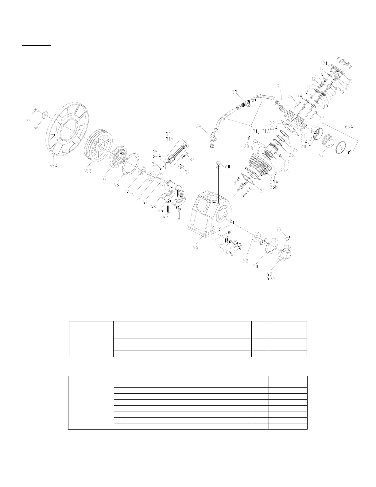
AIR COOLED SINGLE STAGE
MODEL ES-150A
CAP-600
18

MAIN PARTS LISTING FOR
MODEL ES150A
ITEM
NO.
1
2 92521-191000 COPPER WASHER 22
3 70134-57061
4
4a
4b
5 70134-57590
6 70134-57960
7
8
9 70124-57740 OIL GLASS & COVER 1
9a 70124-57700 OIL COVER 1
10 70124-57750 OIL COVER GLASS 1
11 70124-57730 GAUGE COVER SEAL 1
12
13
14 93502-30310 BEARING #30310 1
15 70135-56011 CRANKSHAFT 1
16 701312A1-56032
17 70135-56830 CT R WGT LK WASHER 2
18 70135-56811 CT R WGT MGT BOLT 2
19 70134-56060 V-PULLEY KEY 1
20 93502-32210 BEARING #32210 1
21 70135-57950
22 70134-57080 FRONT OIL SEAL 1
23 70135-57030
24 70135-76011
25 70135-76310 COMP PULLEY FAN 1
26
27
28 70124-76210
29
30
31 70135-51610 CYL & CASE PACKING 3
32 70135-51810 CYL & CASE BOLT 12
33 70135-61281 OIL SPLASH DIPPER 3
34
35 70125-61090
36 70125-61200 CONN.ROD ASS’Y 3
37 70125-61250
38 50135-61081
39 70125-61070
40 70125-61120 PISTON PIN 3
41 70135-61010-1 PISTON 3
42 70135-61050 OIL CONT ROL RING 6
43 70135-61030 COMPRESSION RING 6
44 70135-51011 CYLINDER 3
45
46 70135-11610 CYL & HEAD PACKING 3
47
48 70135-11011 CYLINDER HEAD 3
49 70125-11110
50 70125-31023
PART
NO.
91501-1310025
70131B81-57670
70131BA1-57670
CCC1697
70123-57190-4010
91507-2305016
90112-100404
70135-57010-4024
92522-130800
91501-2308030
92522-131200
91501-1312050
92501-130800
92501-131200
91501-1312035
DESCRIPTION QTY
BOLT, M10 X 25 10
REAR BEARING COVER
TUBE & BRTHR. ASSY. 1
TUBE, BREATHER 1
BREATHER, ASSY. 1
REAR COVER OIL BAFFLE
REAR BRG CVR PACKING
CRANKCASE OIL CAP 1
GAUGE SET BOLT 4
CRANKCASE OIL PLUG 1
CRANKCASE 1
CRANKSHAFT CTR. WGT.
FRONT BEARING GASKET
FRONT BEARING COVER
COMPRESSOR PULLEY
WASHER 6
BOLT 6
PULLEY THRUST WASHER
SPRING WASHER 31
BOLT 1
NUT 3
CONN.ROD CRANK PIN METL
CONN.ROD ASS’Y BOLT
CONN.ROD CRANK PIN METL
PISTON PIN SNAP RING
NUT 12
BOLT 18
I/O VALVE SEAT GASKET
INLET VALVE RECEIVER
CAP-600
ITEM
NO.
51 70125-31070 INLET VALVE SPRING 3
52 70125-31030 PLAT E, INLET VALVE 3
1
53 70125-31010 INT E R VALVE SEAT 3
54 70125-31090
55 70125-11230 UNLOADING SPRING 3
56 70125-31080 I.VALVE UNLOAD FORK 3
1
1
57
58
59 70125-11220 UNLOADING PISTON 3
60 93602-810065 O-RING G#65 3
61 70125-11151 I. VALVE PUSH COVER 3
62
63 90112-100101 SCREW PLUG 3
64 70124-41810 BOLT 3
65 70125-41012 OUT LET VALVE SEAT 3
66
67 70125-41025
68 92501-231000 NUT 6
2
69 93602-870065 VITON O-RING G#65 3
70 70125-11451
71
72 70135-87101
1
73
74 70135-87201
1
1
75
76 70125-41030 PLAT E, OUTLET VALVE 3
77 70125-41001 OUT LET, VALVE ASSY. 3
78 70125-31000 INLET , VALVE ASSY. 3
79 70123-66001 AIR ST RAINER ASSY. 3
1
80 70123-66140 AIR ST RAINER FILTER 3
6
6
3
6
6
3
PART
NO.
92517-231200
93601-810022A
91501-1310025
701212A-41075 OUTLET VALVE SPRING
701312A1-87032
701312A1-87022
701312A2-87011
DESCRIPTION QTY
I. VALVE UNLOAD FORK GUIDE
SLOTTED NUT 3
O-RING P#22A 3
BOLT 24
OUTLET VALVE RECEIVR
O. VALVE PUSH COVER
DIST. MANIFOLD #C 1
COMP.BODY DIS. PIPING
ASSEMBLY
DIST. MANIFOLD #B 1
COMP.BODY DIS. PIPING
ASSEMBLY
DIST. MANIFOLD #A 1
3
9
3
3
1
1
19

AIR COOLED SINGLE STAGE
MODEL ES-150B
CAP-600
18A

ITEM
NO.
91501-1310025
1
9252615-101000-0
2
701310A1-57061 REAR BEARING COVER
3
70131B81-57670
4
70131BA1-57670
4a
CCC1697
4b
701310A1-57590 REAR COVER OIL BAFFLE
5
701310A1-57070 REAR BRG CVR GASKET
6
70123-57190-4010
7
VH1470
8
701210A1-57740
9
701210A1-57700
9a
70124-57750
10
701210A1-57730
11
9156310-400800
12
701312A3-57010
13
9354504-30310
14
701312A1-56011
15
701312A1-56032 CRANKSHAFT CTR. WGT.
16
701312A1-56830
17
701312A1-56811
18
701310A1-56060
19
9354501-32210
20
70135-57950 FRONT BEARING GASKET
21
701310A1-57080
22
701312A1-57030 FRONT BEARING COVER
23
701312A1-76011 COMPRESSOR PULLEY
24
70131283-76310
25
9253113-100800-8
26
9150113-1108030-5202
27
701210A1-76210
28
9253113-101200-8
29
9150113-1112050-5608
30
701312A1-51030
31
701312A1-51810
32
701312A1-61281
33
9250113-120800-538
34
701212A1-61090
35
701212A1-61200
36
70125-61250 CONN.ROD ASS’Y BOLT
37
501312A1-61081
38
701212A1-61070 PISTON PIN SNAP RING
39
701212A1-61120
40
701312A1-61010
41
701212A1-61050
42
701212A1-61030
43
701312A3-51010
44
92501-131200
45
701312A3-11020
46
9250113-121200-538
47
701312A3-11010
48
701212A1-11110
49
PART
NO.
DESCRIPTION QTY
BOLT, M10 X 25 10
COPPER WASHER 10
TUBE & BRTHR. ASSY. 1
TUBE, BREATHER 1
BREATHER, ASSY. 1
CRANKCASE OIL CAP 1
GAUGE SET BOLT 4
OIL GLASS & COVER 1
OIL COVER ASSY 1
OIL COVER GLASS 1
GAUGE COVER SEAL 1
CRANKCASE OIL PLUG 1
CRANKCASE 1
BEARING #30310 1
CRANKSHAFT 1
CTR WGT LK WASHER 2
CTR WGT MGT BOLT 2
V-PULLEY KEY 1
BEARING #32210 1
FRONT OIL SEAL 1
COMP PULLEY FAN 1
WASHER 6
BOLT 6
PULLEY THRUST WASHER
SPRING WASHER 1
BOLT 1
CYL & CASE PACKING 3
CYL & CASE BOLT 12
OIL SPLASH DIPPER 3
NUT 3
CONN.ROD CRANK PIN METL
CONN.ROD ASS’Y 3
CONN.ROD CRANK PIN METL
PISTON PIN 3
PISTON 3
OIL CONTROL RING 6
COMPRESSION RING 6
CYLINDER 3
NUT 12
CYL & HEAD GASKET 3
BOLT 12
CYLINDER HEAD 3
I/O VALVE SEAT GASKET
MAIN PARTS LISTING FOR
MODEL ES150B
ITEM
NO.
701212A1-31023 INLET VALVE RECEIVER 3
50
701212A1-31070
51
1
1
1
2
1
1
1
1
501212A1-31030
52
701212A1-31010
53
701212A1-31090
54
701212A1-11230
55
701212A1-31080
56
9250413-151200-532
57
9360187-350217
58
701212A1-11220
59
9360287-310644
60
701212A1-11151
61
91501-1310025
62
90112-100101
63
70124-41810
64
701212A1-41012
65
701212A1-41075 OUTLET VALVE SPRING
66
701212A1-41025 OUTLET VALVE RECEIVR
67
92501-231000
68
9360287-310644
69
701212A1-11451 O. VALVE PUSH COVER
70
701312A1-87032
71
70135-87101
72
701312A1-87022
73
701312A2-87100
74
701312A2-87011
75
70125-41030
76
701212A1-41001
77
701212A1-31000
78
701312A1-66000
79
701208A1-66110
80
6
6
3
6
6
PART
NO.
CAP-600
DESCRIPTION QTY
INLET VALVE SPRING 3
PLATE, INLET VALVE 3
INTER VALVE SEAT 3
I. VALVE UNLOAD FORK GUIDE
3
UNLOADING SPRING 3
I.VALVE UNLOAD FORK 3
SLOTTED NUT 3
O-RING P#22A 3
UNLOADING PISTON 3
O-RING G#65 3
I. VALVE PUSH COVER 3
BOLT 3
SCREW PLUG 24
BOLT 3
OUTLET VALVE SEAT 3
3
9
NUT 3
VITON O-RING G#65 6
3
DIST. MANIFOLD #C 3
COMP.BODY DIS. PIPING
ASSEMBLY
1
DIST. MANIFOLD #B 1
COMP.BODY DIS. PIPING
ASSEMBLY
1
DIST. MANIFOLD #A 1
PLATE, OUTLET VALVE 1
OUTLET, VALVE ASSY. 3
INLET, VALVE ASSY. 3
AIR STRAINER ASSY. 3
AIR STRAINER FILTER 3
19A

AIR COOLED
TWO STAGE MODELS E-11 & E-23
CAP-600
20

MAIN PARTS LISTING FOR
t
t
t
t
t
t
d
d
d
d
d
d
d
t
t
t
t
t
t
t
t
d
d
d
d
d
d
d
d
TWO STAGE MODELS E-11 & E-23
VALVES
1. Inlet & Outlet Valve Plate (1
2. Inlet Valve Spring (1
3. Inlet Valve Receiver (1
4. Inlet Valve Snap Ring (1
5. Outlet Valve Spring (1
6. Outlet Valve Push Cover Gasket (1
7. Outlet Valve Push Cover 1 70112-11450 2 70112-11450
8. Inlet & Outlet Valve Plate (2
9. Inlet Valve Spring (2
10. Inlet Valve Receiver (2
11. Inlet Valve Snap Ring (2
12. Outlet Valve Spring (2
14. Outlet Valve Push Cover Gasket (2
15. Outlet Valve Push Cover (2
CYLINDERS
16. Cylinder Head (1
17. Cylinder & Head Gasket (1
18. Cylinder (1
19. Cylinder & Case Gasket 2 70112-51610 3 70112-51610
20. Compression Ring (1
21. Oil Control Ring (1
22. Piston (1
23. Piston Pin (1
24. Piston Pin Snap Ring 4 70112-61070 6 70112-61070
25. Connecting Rod Assembly (1
26. Connecting Rod Bolt 2 70112-61250 3 70112-61250
27. Oil Splash Dipper 70122-61282 2 70122-61282
27A. Oil Splash Dipper - 1 70132-61290
28. Oil Splash Dipper Bolt 2 91507-2304010 3 91507-2304010
29. Cylinder Head Bolt 8 91501-1308025 12 91501-1308025
30. Cylinder Head (2
31. Cylinder & Head Gasket (2
32. Cylinder (2
34. Compression Ring (2
35. Oil Control Ring (2
36. Piston (2
37. Piston Pin (2
38. Connecting Rod Assembly (2
39. Crankcase 1 70122-57010-4024 1 70132-57010-4024
40. Crankshaft 1 70122-56010 1 70132-56010
41. Front Bearing Cover 1 70122-57030 1 70122-57030
42. Front Bearing Cover Gasket 1 70122-57950 1 70122-57950
43. Rear Bearing Cover 1 70122-57060 1 70122-57060
44. Rear Bearing Cover Gasket 1 70122-57960 1 70122-57960
45. Bearing 2 93501-6205 2 93501-6205
46. Front Oil Seal 1 70122-57080 1 70122-57080
47. V–Pulley Pin 1 70112-56060 1 70112-56060
48. Compressor Pulley 1 70122-76011 1 70132-76010
49. Compressor Pulley Thrust Washer 1 70112-76210 1 70112-76210
50. Compressor Pulley Thrust Bolt 1 91501-1308025 1 91501-1308025
51. Breather Assembly 1 CCC1375 1 CCC1375
52. Oil Gauge & Gauge Cover 1 70111-57700 1 70111-57700
٭52 A. Oil Level Gauge Assy. 1 70A109B1-57701 1 70704-57700
53. Gauge Cover Seal 1 70111-57730 1 70111-57730
٭53 A. Oil Level Gauge “O” Ring 1 93602-8126026 1 93602-8126026
54. Crankcase Oil Plug 1 90112-100202 1 90112-100202
54A. Oil fill cap - 1 70101-57190-4010
54B. “O” Ring - 1 93601-810016
55. Auto-Unloader Assembly 2 70112-11201 3 70112-11201
56. Auto-Unloader Spring 2 70112-11230 3 70112-11230
57. Auto-Unloader Piston 2 70112-11221 3 70112-11221
58. O-Ring (Unloader) 2 93601-810016 3 93601-810016
AIR STRAINER ASSEMBLY
61. Air Strainer Filter (not shown) 1 70111-66141 2 70111-66141
63A. Discharge Piping Assembly - 1 70132-87100
63B. Discharge Piping Assembly 1 70172-87300 1 70172-87300
64. Air Strainer Assembly 1 70111-66001 2 70111-66001
65. Outlet Pipe Joint #A 2 70122-87010 3 70122-87010
65A. Outlet Pipe Joint #B 1 70132-87020
• E11, START S/N AS4040633
• E23, START S/N AS4030313
s
s
) 1 70112-51010 2 70112-51010
s
) 1 70112-61011 2 70112-61011
s
) 1 70112-61120 2 70112-61120
n
n
) 1 70162-52010 1 70172-52010
n
) 1 70162-62010 1 70172-62010-1
n
) 1 70162-62120 1 70172-62120
CRANK ASSEMBLY
UNLOADERS
s
) 2 70112-31030 4 70112-31030
s
) 1 70112-31070 2 70112-31070
s
) 1 70112-31020 2 70112-31020
s
) 1 93610-130232 2 93610-130232
s
) 1 70112-41070 2 70112-41070
n
) 1 70162-32070 2 70172-32070
n
) 1 70162-32020 1 70111-31020
n
n
) 1 70162-42070 1 70172-42070
) 1 70112-11010 2 70112-11010
s
) 2 70112-61030 4 70112-61030
s
) 1 70112-61050 2 70112-61050
) 1 70162-12010 1 70172-12010
n
) 2 70162-62030 2 70111-61030
n
) 2 70162-62050 2 70111-61050
s
) 1 70112-11461 2 70112-11461
n
) 2 70162-32030 2 70111-31030
) 1 93610-130222 1 93610-130225
n
) 1 70162-12650 1 70111-11461
n
) 1 70112-12450 1 70111-11450
s
) 1 70112-11612 2 70112-11612
s
) 2 70112-61200-1 2 70112-61200-1
n
) 1 70162-12610 1 70111-11612
n
) - 1 70182-62200
Qty.
Req.
MODEL E11
Qty.
Req.
CAP-600
MODEL E23
21

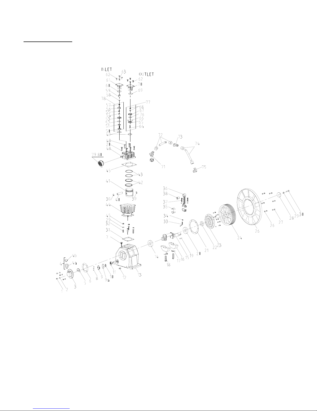
AIR COOLED, TWO STAGE CAP600
t
d
t
d
MODELS E-50 & E-71
DESCRIPTIONS Qty. Req.
Inlet Valve Assembly, 1
Inlet Valve Assembly, 2
Outlet Valve Assembly, 1
VALVE
Outlet Valve Assembly, 2
ASSEMBLIES
Breather Assembly 1 70103-57600-4024 1 70124-57600-4010
DESCRIPTIONS
1. Inlet Valve Seat 2 70123-31010 1 70123-31010 2 70124-31010 1 70123-31010
2. Inlet Valve Receiver 2 70123-31020 1 70123-31020 2 70124-31020 1 70123-31020
3. Inlet & Outlet Valve Plate 4 70123-31030 2 70123-31030 4 70124-31030 2 70123-31030
4. Inlet Valve Spring 2 70123-31070 1 70123-31070 2 70124-31070 1 70123-31070
5. Inlet Valve Unloading Fork Guide 2 70123-31090 1 70123-31090 2 70124-31090 1 70123-31090
6. Unloading Spring 2 70123-11230 1 70123-11230 2 70124-11230 1 70123-11230
7. Inlet Valve Unloading Fork 2 70123-31080 1 70123-31080 2 70124-31080 1 70123-31080
8. Slotted Nut 2 92502-230800 1 92502-230800 2 92502-230800 1 92502-230800
9. Cotter Pin (not shown) 2 93701-130220 1 93701-130220 2 93701-130220 1 93701-130220
10. Outlet Valve Seat 2 70123-41011 1 70123-41011 2 70124-41011 1 70123-41011
VAVLES & UNLOADERS
11. Outlet Valve Receiver 2 70123-41020 1 70123-41020 2 70124-41020 1 70123-41020
12A. Seat Gaskets 4 70123-11110 2 70123-11110 4 70124-11110 2 70123-11110
MODEL
s
Stage 2 70123-31000 2 70124-31000
n
Stage 1 70173-32000 1 70173-32000
s
Stage 2 70123-41000 2 70124-41000
n
Stage 1 70123-41000 1 70123-41000
E50
Qty. Req.
MODEL
E71
MAIN PARTS LISTING FOR
TWO STAGE MODELS E-50 & E-71
MODEL E50 MODEL E71
Qty
Req’d
st
1
Stage
22
Qty
Req’d
2nd Stage
Qty
Req’d
1st Stage
Qty
Req’d
2nd Stage
CAP-600
MAIN PARTS LISTING FOR
TWO STAGE MODELS E-50 & E-71 (CONTINUED)
MODEL E-50 MODEL E-71
12B Outlet Valve Spring 2 70123-41070 1 70123-41070 2 70124-41070 1 70123-41070
13 Outlet Valve Bolt 2 70123-41810 1 70123-41810 2 70124-41810 1 70123-41810
14 Nut (Outlet Valve) 2 92502-230800 1 92502-230800 2 92502-230800 1 92502-230800
15 Inlet Valve Push Cover 2 70123-11150 1 70123-11150 2 70124-11150 1 70123-11150
16 O-ring G-40(Inlet Valve) 2 93602-810040 1 93602-810040 2 93602-810055 1 93602-810055
17 Viton O-ring G-40 (Outlet Valve) 2 93602-870040 1 93602-870040 2 93602-870055 1 93602-870040
18 Unloading Piston 2 70123-11220 1 70123-11220 2 70124-11220 1 70123-11220
19 O-ring P-20 2 93601-810020 1 93601-870020 2 93601-810021 1 93601-870020
20 Outlet Valve Push Cover 2 70123-11450 1 70123-11450 2 70124-11450 1 70123-11450
Valves & Unloaders
20A Iinterstage Safety Valve (E71 only) - N/A - N/A 1 93132-15006-40101 - N/A
21 Cylinder Head (1st) 2 70123-11010 2 70124-11010
22 Cylinder & Head Gasket 2 70123-11612 1 70123-11612 2 70124-11612 1 70123-11612
23 Cylinder (1st) 2 70123-51012 2 70124-51011
23A S/N A311xxxx & Later Use 2 70123-51012 2 70124-51011
24 Cylinder & Case Gasket 2 70123-51610 1 70123-51610 2 70124-51610 1 70124-51610
25 Compression Ring (1st) 4 70123-61030 4 70124-61030
26 Oil Control Ring (1st) 4 70123-61050 4 70124-61050
27 Piston (1st) 2 70123-61011 2 70124-61011-1
27A S/N 3020000 & Later Use 2 70123-61011 2 70124-61011-1
28 Piston Snap Ring 4 70123-61070 2 70123-61070 4 70124-61070 2 70124-61070
29 Piston Pin (1st) 2 70123-61120 2 70124-61120
30 Con’cting Rod Pist. Pin Bushing 2 70123-61081 1 70173-62080 2 70124-61080 1 70174-62081
30A Bushing S/N 3020000 & Later use 2 70123-61081
30B Nedl Brg.S/N A303XXXX&LatrUse 1 93503-RNA6903R
30C Nedl Brg.(2nd)S/N A405XXXX&Latr 1 93503-TA1725
31 Connecting Rod Assy 2 70123-61200 1 70173-62200 2 70124-61201 1 70174-62202
Cylinders
31B
32 Connecting Rod Crank Pin Metal 4 70123-61090 2 70123-61090 4 70124-61090 2 70124-61090
33 Connecting Rod Bolt 4 70125-61250 2 70125-61250 4 70125-61250 2 70125-61250
34 Oil Splash Dipper 2 70122-61282 1 70132-61290 2 70134-61281 1 70134-61290
35 Oil Splash Dipper Bolt 2 91507-2304012 1 91507-2304012 2 91507-2304012 1 91507-2304012
36 Cylinder Head (2nd) 1 70123-11010 1 70174-12010
37 Cylinder (2nd) 1 70173-52010 1 70174-52011
37A Cyl (2nd),S/N 3020000 & Later Use 1 70174-52011
38 Compression Ring (2nd) 3 70112-61030 3 70123-61030
39 Oil Control Ring (2nd) 1 70112-61050 2 70123-61050
40 Piston (2nd) 1 70173-62010-1 1 70174-62010-1
41 Piston Pin (2nd) 1 70173-62120 1 70174-62120
42 Crankshaft 1 70133-56011 1 70134-56010
43 Crankshaft, Counterweight - 1 70134-56030
44 Counterweight Lock Washer - 2 70124-56830
45 Counterweight Mtg. Bolt - 2 70124-56810
46 Crankcase 1 70133-57010-4024 1 70134-57010-4024
47 Front Bearing Cover 1 70133-57030 1 70134-57030
48 Front Bearing Cover Gasket 1 70123- 5795 0 1 70124-57950
49 Rear Bearing Cover 1 70133-57061 1 70134-57061
49A Rear Brg Cvr, S/N 3020000 & Later 1 70133-57061 1 70134-57061
50 Rear Brg Cvr Gasket 1 70133-57960 1 70134-57960
51 Front Bearing 1 93501-6306 1 93502-32210
52 Rear Bearing 1 93501-6306 1 93502-32210
53 Front Oil Seal 1 70123-57080 1 70134-57080
54 V-Pulley Pin 1 70123-56061 1 70134-56060
55A Compressor Fan - 1 70124-76310
55B Compressor Pulley 1 70133-76010 1 70134-76011
56 Compressor Pulley Washer 1 92521-232000 1 70124-76210
57 Compressor Pulley Set Bolt 1 91501-1312030 1 91501-1312040
58 O-Ring (Oil Level Glass) 1 93602-81260-3065 - - - -
59 Screw In Oil Level Glass 1 70A109B1-57702 - - - -
60 Crankcase Oil Cap 1 CCC1257 1 CCC1257
61 Crankcase Oil Plug 1 90112-100404 1 90112-100404
62 Breather Assembly 1 CCC1375 1 CCC1258
66A Air Strainer Assembly 2 70123-66000 2 70123-66000
Crankcase & Crank Assembly
67 Air Strainer Filter 2 70123-66140 2 70123-66140
69 Outlet Pipe Joint B 1 70123-87020 1 70174-87020
70A Comp.body.discharg.pipe.assy. 1st 1 70133-87101 short 1 70134-87101 short
70B Comp.body.discharg.pipe.assy. 1st - -
70C Comp.body.discharg.pipe.assy.2nd - -
70D Comp.body.discharg.pipe.assy.2nd 1 70173-87300 long 1 70174-87300 long
71 Outlet Pipe Joint A 2 70123-87010 3 70124-87010
72 Outlet Pipe Joint D 1 70173-87010
73 Outlet Pipe Joint C
74 Gasket Manifold - -
75 Oil Level Glass Gasket 1 701210A1-57730 1 701210A1-57730
76 Oil Level Glass Assembly 1 701210A1-57700 1 701210A1-57700
77 Oil Level Glass Push Cover 1 701210A1-57740 1 701210A1-57740
78 Screw, Metric Pan Head 4 VH1470 4 VH1470
DESCRIPTION
nd
Conn. Rod Assy., 2
A405XXXX & Later Use
Stage S/N
QTY
1 70173-62200
1st Stage
QTY
23
2nd Stage
QTY
1st Stage
QTY
2nd Stage

AIR COOLED, TWO STAGE
t
d
t
d
MODEL E-15
CAP-600
VALVE ASSEMBLIES
VAVLES & UNLOADERS
MAIN PARTS LISTING FOR TWO STAGE MODEL E-15
Description
1. Inlet Valve Seat 2 70125-31010 1 70124-31010
2. Inlet Valve Receiver 2 70125-31022 1 70124-31020
3. Inlet & Outlet Valve Plate 4 70125-31030 2 70175-42030
4. Inlet Valve Spring 2 70125-31070 1 70124-31070
5. Inlet Valve Unloading Fork Guide 2 70125-31090 1 70124-31090
6. Unloading Spring 2 70125-11230 1 70124-11230
7. Inlet Valve Unloading Fork 2 70125-31080 1 70124-31080
8. Slotted Nut 2 92502-230800 1 92502-230800
9. Cotter Pin (not shown) 2 93701-130220 1 93701-130220
10. Outlet Valve Seat 2 70125-41011 1 70124-41010
11. Outlet Valve Receiver 2 70125-41021 1 70175-42020
12A. Seat Gaskets 4 70125-11110 2 70124-11110
Description
Inlet Valve Assembly, 1
Inlet Valve Assembly, 2
Outlet Valve Assembly, 1
Outlet Valve Assembly, 2
Qty.
s
Stage 2 70125-31000
n
Stage 1 70175-32000
s
Stage 2 70125-41000
n
Stage 1 70175-42000
Req.
MODEL
E15
Breather Assembly 1 70124-57600-4010
MODEL E15
Qty
Req’d
st
1
Stage
Qty
Req’d
nd
2
Stage
24

CAP-600
t
t
t
t
t
t
t
d
t
d
d
d
d
d
d
d
d
d
t
t
d
d
MAIN PARTS LISTING FOR
TWO STAGE MODEL E-15 (Continued)
DESCRIPTION
Qty
Req’d
st
1
Stage
12B. Outlet Valve Spring 2 70125-41071 1 70124-41072
13. Outlet Valve Bolt 2 70124-41810 1 70124-41810
14. Nut (Outlet Valve) 2 92501-231000 1 92501-231000
15. Inlet Valve Push Cover 2 70125-11151 1 70175-12150
16. O-Ring G-65 (Inlet Valve) 2 93602-810065 1 93602-870055
17. Viton O-Ring G-65 (Outlet Valve) 2 93602-870065 1 93602-870055
18. Unloading Piston 2 70125-11220 1 70124-11220
VALVES &
UNLOADERS
19. O-Ring P-20 2 93601-810022A 1 93601-870021
20. Outlet Valve Push Cover 2 70125-11451 1 70175-12450
20A. Outlet Valve Push Cover Push Pipe 1 70124-11120
21. Cylinder Head (1
s
) 2 70125-11010
21A. S/N A31XXXX & Later Use 2 70135-11010
22. Cylinder & Head Gasket 2 70125-11612 1 70124-11612
22A. S/N A311XXXX & Later Use 2 70135-11612
23. Cylinder (1
s
) 2 70125-51010
23A. S/N A311xxxx & Later Use 2 70135-51011
24. Cylinder & Case Gasket 2 70135-51610
25. Compression Ring (1
26. Oil Control Ring (1
27. Piston (1
s
) 2 70135-61010-1
s
) 4 70125-61030
s
) 4 70125-61050
27A. S/N 3020000 & Later Use 2 70135-61010-1
28. Piston Snap Ring 4 70125-61070 2 70125-61070
29. Piston Pin (1
30. Connecting Rod Piston Pin Bushing (1
30D. Needle Bearing (2
31. Connecting Rod Assembly, 1
31C. Connecting Rod Assembly, 2
CYLINDERS
32. Connecting Rod Crank Pin Metal 4 70125-61090 2 70125-61090
s
) 2 70125-61120
n
) S/N A409XXXX & Later Use 1 93503-NK28/30
s
) 2 70125-61081 1 70175-62080
s
Stage 2 70125-61200 1 70175-61200
n
Stage 1 70175-62201
33. Connecting Rod Bolt 4 70125-61250 2 70125-61250
34. Oil Splash Dipper 2 70135-61281 1 70135-61281
35. Oil Splash Dipper Bolt 2 92501-130800 1 92501-130800
36. Cylinder Head (2
37. Cylinder (2
38. Compression Ring (2
39. Oil Control Ring (2
40. Piston (2
40A. Piston (2
41. Piston Pin (2
41A. Piston Pin (2
n
) 1 70175-12010
n
) 1 70175-52010
n
) 3 70124-61030
n
n
n
) 2 70124-61050
) 1 70175-62010-1
), S/N A409XXXX & Later Use 1 70175-62011-1
n
) 1 70175-62120
n
), S/N A409XXXX & Later Use 1 70175-62121
42. Crankshaft 1 70135-56011
43. Crankshaft Counterweight 1 70135-56030
44. Counterweight Lock Washer 2 70124-56830
45. Counterweight Mounting Bolt 2 70135-56811
46. Crankcase 1 70135-57010-4024
47. Front Bearing Cover 1 70135-57030
48. Front Bearing Cover Gasket 1 70135-57950
49. Rear Bearing Cover 1 70134-57061
49A. Rear Bearing Cover, S/N 3020000 & Later Use 1 70134-57061
50. Rear Bearing Cover Gasket 1 70134-57960
51. Front Bearing 1 93502-30310
52. Rear Bearing 1 93502-32210
53. Front Oil Seal 1 70134-57080
54. V-Pulley Pin 1 70134-56060
55A. Compressor Fan 1 70135-76310
55B. Compressor Pulley 1 70135-76011
56. Compressor Pulley Washer 1 70135-76210
57. Compressor Pulley Set Bolt 1 91501-1312050
60. Crankcase Oil Cap 1 CCC1257
61. Crankcase Oil Plug 1 90112-100404
62. Breather Assembly 1 70124-57600-4010
66A Air Strainer Assembly 2 70123-66000
67. Air Strainer Filter 2 70123-66140
69. Outlet Pipe Joint B 1 70175-87021
70A. Compressor Body Discharge Piping Assembly, 1
CRANKCASE AND CRANK ASSEMBLY
70B. Compressor Body Discharge Piping Assembly, 1
70C. Compressor Body Discharge Piping Assembly, 2
70D. Compressor Body Discharge Piping Assembly, 2
s
1 70135-87100(long)
s
1
n
1
n
1 70175-87300(long)
70135-87200(short)
70175-87400(short)
71. Outlet Pipe Joint A 1 70175-87010
72. Outlet Pipe Joint D (not shown) 1 70125-87020
73. Outlet Pipe Joint C 1 70175-87030-4010
74. Gasket Manifold 4 70125-87510
75 Oil Level Glass Gasket 1 701210a1-57730
76 Oil Level Glass Assembly 1 701210a1-57700
77 Oil Level Glass Push Cover 1 701210a1-57740
78 Screw, Metric Pan Head 4 VH1470
MODEL E15
Qty
Req’d
2nd Stage
25

CAP 600
AIR COOLED, TWO STAGE
MODEL E
-
25
25A

CAP-600
MAIN PARTS LISTING FOR
TWO STAGE MODEL E-25
Item
No.
Description
Qty
Req.
1 CRANKCASE 1
2 OIL SIGHT GLASS GASKET 1
3 OIL SIGHT GLASS ASSY. 1
4 OIL SIGHT GLASS PUSH COVER 1
5 OIL SIGHT GLASS BOLT; M5 x L20, Gr.8.8 4
6 BOLT M12*1.25*L10 1
7 OIL NOZZLE 2
8 PIPE 1
9 PIPE CAP 1
10 CRANK SHAFT 1
11 FRONT & REAR BEARING 2
12 REAR BEARING COVER GASKET 1
13 REAR BEARING COVER 1
14 REAR OIL SEAL 1
15 CENTRIFUGAL FAN LOCK WASHER; M10 12
16 CENTRIFUGAL FAN BOLT; M10 X L30, Gr.8.8 12
17 FIX PLATE 1
18 PRESSURE SWITCH 1
19 O-RING (OIL FILL CAP) 1
20 OIL FILL CAP 1
70131EB2-57010
70124-57730
70124-57700
70124-57740
91507-2305020
9152813-1Z12010
703213A1-561070
9011023-1604604
9092017-1304000
70131EB2-56010
93501-33112
70178-57070
70131EB2-57060
70131EB2-57090
92521-231000
91501-2310030-8
70131EB2-57930
93301-990005
93601-810018
70123-57190
21 CYLINDER – CASE GASKET (2ND)
22 CONNECTING ROD CRANK PIN 6
23 CONNECTING ROD BOLT 6
24 LOCKWASHER (M12) 6
25 NUT; (M12) 6
26 CONNECTING ROD 3
27 CONNECTING ROD – PISTON PIN NEEDLE BEARING 3
28 PISTON PIN SNAP RING 6
70178-61090
70178-61250
92522-131200
92501-131200-8
70131EB2-61210
93501-3230
93610-130032
29 PISTON (2ND)
30 PISTON (2ND)
31 OIL CONTROL RING (2ND)
32 COMPRESSION RING (2ND)
33 CYLINDER BOLT (1ST); M16 x L46, Gr. 8.8 12
34 CYLINDER LOCK WASHER; M16 x L46, Gr. 8.8 13
35 CYLINDER NUT; M16 12
91525-1316045-8
92522-131600
92501-131600
36 CYLINDER (2ND)
37 VALVE – CYLINDER GASKET (2ND) 1
38 INLET & OUTLET VALVE GASKET (2ND) 2
39 OUTLET VALVE BOLT; M10 X L50, Gr. 8.8 1
9152613-1110050
40 OUTLET VALVE SEAT (2ND)
41 OUTLET VALVE SPRING (2ND)
42 OUTLET VALVE RECEIVER (2ND) 1
43 OUTLET VALVE PLATE (2ND)
44 NUT; M10 (Outlet Valve) 6
92501-231000
45 INLET VALVE RECEIVER (2ND)
46 INLET VALVE PLATE (2ND)
47 INLET VALVE SPRING (2ND)
48 INLET VALVE SEAT (2ND)
49 INLET VALVE UNLOADER FORK (2ND) 1
50 UNLOADER SPRING 3
70125-11230
Model E-25
st
Stage
1
Qty
Req.
nd
2
Stage
1 70178-52030
70131EB2-62120
1
70131EB2-62010
1
70178-62050
2
70178-62030
3
1
70178-52010
70178-31240
70125-11110
70125-41011
1
70125-41074
3
701212A1-41026
501212A1-41032
1
70125-31023
1
50125-31030
1
70125-31070
1
70125-31010
1
70125-31080
25B
MAIN PARTS LISTING FOR CAP600
TWO STAGE MODEL E-25
Item
Description
No.
51 INLET VALVE UNLOADER FORK GUIDE
52 LOCKNUT; M12 (Inlet Valve)
53 AIR OUTLET JOINT
54 CYLINDER HEAD (2ND)
55 CYLINDER HEAD BOLT SPRING WASHER; M12
56 CYLINDER HEAD BOLT; M12 x L35; Gr. 8.8
57 O-RING P 22A (Unloader)
58 UNLOADER PISTON
59 O-RING G65 (Outlet Valve)
60 O-RING G65 (Inlet Valve)
61 INLET VALVE PUSH COVER (2ND)
62 OUTLET VALVE PUSH COVER (2ND)
63 OUTLET VALVE PUSH COVER BOLT; M10 x L25, Gr. 8.8
64 PISTON PIN (1ST)
65 PISTON (1ST)
66 OIL CONTROL RING (1ST)
67 COMPRESSION RING 2 (1ST)
68 COMPRESSION RING 1 (1ST)
69 CYLINDER – CASE GASKET (1ST)
70 CYLINDER (1ST)
71 VALVE - CYLINDER GASKET (1ST)
72 INLET & OUTLET VALVE GASKET (1ST)
73 INLET VALVE RECEIVER (1ST)
74 INLET VALVE SPRING (1ST)
75 INLET VALVE PLATE 1 (1ST)
76 INLET VALVE PLATE 2 (1ST)
77 INLET VALVE SEAT (1ST)
78 INLET VALVE STUD
79 OUTLET VALVE SEAT (1ST)
80 OUTLET VALVE SPRING (1ST)
81 OUTLET VALVE RECEIVER (1ST)
82 OUTLET VALVE STUD
83 INLET VALVE UNLOADER FORK (1ST)
84 CYLINDER HEAD (1ST)
85 O-RING G85.7
86 INLET VALVE PUSH COVER (1ST)
87 OUTLET VALVE PUSH COVER (1ST)
88 OUTLET VALVE PUSH COVER BOLT; M10 x L30, Gr. 8.8
89 OIL SEAL
90 FRONT OIL SEAL PUSH COVER
91 FRONT OIL SEAL PUSH COVER BOLT; M8 x L25, Gr. 8.8
92 CENTRIFUGAL FAN
93 LOCK WASHER, M6
94 BOLT; M6 x L10, Gr. 8.8
95 COMPRESSOR PULLEY
96 COMPRESSOR PULLEY THRUST WASHER
97 V-PULLEY PIN
98 COMPRESSOR PULLEY BOLT; M16 x L30, Gr. 8.8
99 INTERCOOLER – HEAD GASKET
100 PIPING-INTERCOOLER LOCK WASHER; M10
Model E-25
Qty
Req
1 70125-31090
1 92517-231200
1 70131EB1-87021
1 70181EB3-12010
18 92522-131200
18 9150113-1112035
3 93601-870022A
3 70125-11220
1 93602-870065
1 93602-810065
1 70125-11151
1 70125-11451
8 91501-1310025-8
2 70178-61120
2 70131EB2-61010
4 70178-61050
4 70178-61030-2
2 70178-61030-1
2 70178-51030
2 70181EB3-51010
2 70181EB3-11202
4 70181EB3-31110
2 70181EB3-31020
6 70181EB3-31070
2 70181EB3-31050
2 70181EB3-31030
2 70181EB3-31010
2 70181EB3-31810
2 70181EB3-41010
6 70181EB3-41070
2 70181EB3-41020
2 70131BA4-41810
2 70181EB3-31080
2 70181EB3-11010
2 9360287-310857
2 70181EB3-11150
2 70181EB3-11450
16 CT55-1310030
1 70178-57080
1 70178-57240
4 91501-2308025-8
1 70A81EB1-76300
12 92522-130600
12 91513-1306010
1 70178-76010
1 70178-76210
1 70718-56060
1 91501-2316045-8
1 70178-71020
14 92522-13100
st
1
Stage
Qty
Req
2nd Stage
25C

MAIN PARTS LISTING FOR CAP600
TWO STAGE MODEL E-25
Item
No.
Description
101 PIPING-INTERCOOLER BOLT; M10 x L30, Gr. 8.8
102 PIPING- INTERCOOLER GASKET
103 DISCHARGE PIPING ASSEMBLY
104 MIDDLE INTERCOOLER ASSEMBLY
105 COMPRESSOR FAN
106 COMPRESSOR FAN WASHER, M8
107 COMPRESSOR FAN LOCK WASHER, M8
108 COMPRESSOR FAN BOLT; M8 x L30, Gr. 8.8
109 PIPING-HEAD GASKET
110 DISCHARGE PIPING ASSEMBLY
111 GEAR PUMP COUPLING
112 BOLT; M6*15
113 NUT; M6
114 GEAR PUMP HOUSING GASKET
115 GEAR PUMP HOUSING
116 STEEL BALL
117 BALL VALVE RECEIVER
118 PRESSURE GAUGE (0~10K)
119 BALL VALVE SPRING
120 REGULATOR SEALING
121 REGULATOR ADJUST NUT
122 REGULATOR ADJUST BOLT
123 GEAR PUMP SHAFT
124 DRIVE GEAR RING
125 DRIVE GEAR
126 DIRVEN GEAR
127 O-RING
128 GEAR PUMP HOUSING COVER
129 LOCK WASHER, M10
130 BOLT; M10*30
131 COPPER PIPE JOINT
132 PUMP CONNECTING TUBE
133 STRAINER PLUG
134 FEED OIL FILTER ASSEMBLY
135 BREATHER ASSEMBLY (RUBBER)
136 BREATHER TUBE
137 ELBOW 45º
138 NIPPLE ½
139 AIR FILTER ASSEMBLY
Model E-25
Qty
Req
14 91513-1310030-8
2 70178-87090
1 70178-87100
1 70131EB1-71000C
1 70178-76310
6 92521-230800
6 92522-130800
6 91501-92308030-8
2 70178-87130-1
1 70178-87200
1 703213A1-27110
1 91501-2306015
1 92501-130600
1 703213A1-27020
1 70131EB2-27010
1 9980113-20036
1 703213A1-28090
1 9320611-2032213
1 703213A1-28080
1 703213A1-28110
1 703213A1-28130
1 703213A1-28120
1 703213A1-27070
1 703213A1-27130
1 703213A1-27050
1 703213A1-27060
1 9360281-31044
1 70131EB2-27030
3 92522-131000
3 91501-2310030
1 7992013-2204050
1 70131EB2-27080
1 703213A1-28530
1 703213A1-28500
1 701312A1-57601
1 70131BA1-57670
1 9010311-1304304
1 9011013-1304304
2 70178-66000
st
1
Stage
Qty
Req
2nd Stage
25D
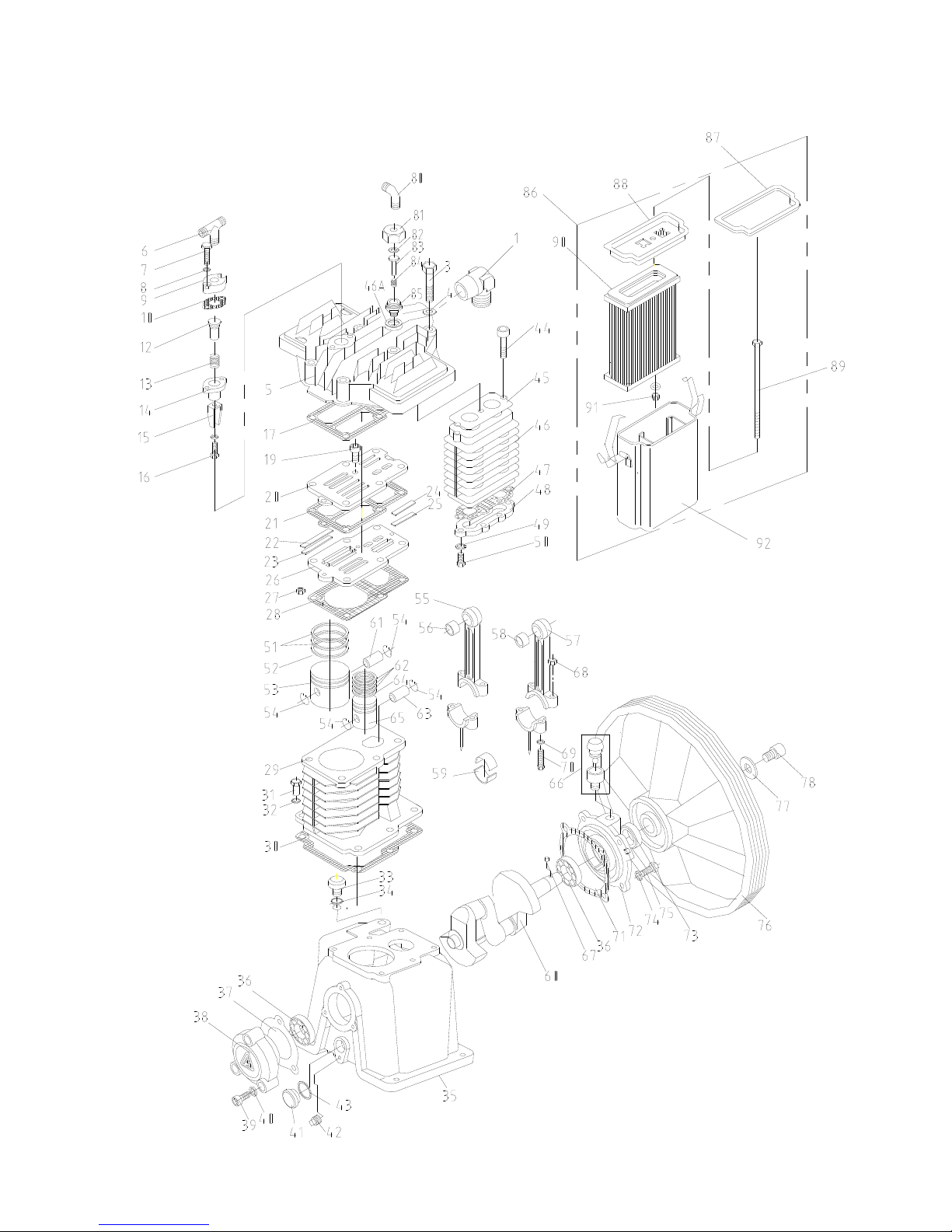
AIR COOLED TWO STAGE MODEL E-35
CAP-600
26
MAIN PARTS LISTING FOR
t
t
t
t
d
d
t
t
t
t
t
d
d
t
d
d
d
d
d
d
d
d
d
AIR COOLED TWO STAGE MODEL E-35
(FORMERLY B-1)
DESCRIPTION QTY PART NO.
1. Discharge Elbow 1 70123-87050
2. Discharge Elbow Nut (Not Shown) 1 79922-130606
3. Cylinder Head Bolt 6 91501-1310085
4. Spring Washer 6 92522-130800
5. Cylinder Head 1 70152-11010
6. Unloading Tee * # 1 79922-150101
7. Bolt 2 91521-1306025
8. Spring Washer 2 92522-130600
9. Upper Cover 1 70153-11270
10. Upper Cover Gasket 1 70153-11641
Unloader Assembly (1
11.
16)
12. Unloading Piston 1 70153-11222
13. Unloading Spring 1 70153-11231
14. Unloading Cylinder 1 70153-11211
15. Unloading Fork (1
16. Bolt 1 91501-1306015
17. Cylinder Head Valve Seat Gasket 1 70152-11612
18. Valve Plate Assembly (Includes 19-27) 1 70152-31000
19. Valve Seat Bolt 3 91521-1305012
20. Valve Seat (Upper) 1 70152-31010
21. Valve Seat Gasket 1 70152-31120
22. Valve Plate (1
23. Valve Plate Spring (1
24. Valve Plate (2
25. Valve Plate Spring (2
26. Valve Seat (Bottom) 1 70152-31020
27. Nut 1 92501-230500
28. Cylinder-Valve Seat Gasket 1 70152-11622
29. Cylinder 1 70152-51010
30. Cylinder Crankcase Gasket 1 70152-51610
31. Bolt 11 91501-1310030
32. Copper Washer 6 92521-190800
33. Crankcase Oil Cap 1
34. Oil Cap O-Ring 1 93601-810016
35. Crankcase 1 70152-57010
36. Bearing #6025 (Front & Rear) 2 93501-6205
37. Rear Cover Gasket 1 70152-57960
38. Rear Cover 1 70152-57060
39. Rear Cover Bolt 3 91521-1308030
40. Copper Washer 7 92521-190800
41. Oil Level Gauge & Gauge Cover 1 70111-57700
42. Gauge Cover Seal 1 70111-57730
43. Crankcase Oil Plug (1/4” NPT) 1 90112-100303
44. Inter-Cooler Bolt 3 91521-1308050
45. Gasket 1 70152-71612
46. Inter-Cooler Body 1 70152-71110
46A. Gasket, Copper 1 70152-12280
s
)(Includes 12-
s
) 1 70152-31080
s
) 4 70152-31030
s
) 4 70152-31070
n
) 2 70152-32030
n
) 2 70152-32070
1 70152-11201
70101-57190-4010
*Includes Nut(S) and Sleeve(S) #Not Supplied On Basics
CAP-600
DESCRIPTION QTY PART NO.
47. Inter-Cooler Body Gasket 1 70152-71622
48. Inter-Cooler Cover 1 70152-71160
49. Spring Washer 4 92522-130600
50. Bolt 4 91501-1306016
51. Compression Ring (1
52. Oil Control Ring (1
53. Piston (1
s
) 1 70152-61010
54. Piston Snap Ring 4 70152-61070
55. Connection Rod Assembly (1
56. Piston Pin Bush (1
57. Connecting Rod Assembly (2
58. Piston Pin Bush (2
59. Crank Pin Metal (Rod Bearing 2 Halves) 2 70152-61090
60. Crankshaft 1 70152-56010
61. Piston Pin (1
62. Compression Ring (2
63. Piston Pin (2
64. Oil Control Ring (2
65. Piston (2
n
) 1 70152-62010
66. Breather Assembly 1
67. V-Pulley Pin 1 70112-56060
68. Nut (Connecting Rod) 4 92501-130800
69. Spring Washer (Connecting Rod) 4 92522-130800
70. Bolt (Connecting Rod) 4 70152-61250
71. Front Cover Gasket 1 70152-57950
72. Front Cover 1 70152-57030
73. Front Oil Seal 1 70127-57 080
74. Copper Washer 7 92521-190800
75. Bolt 4 91501-1310030
76. Compressor Pulley 1 70152-76010
77. Compressor Pulley Thrust Washer 1 70112-76210
78. Bolt 1 91501-1308025
79. Unloading Elbow * # 1 79926-150101
Unloader Assembly (2
80.
85)
81. Unloader Cover (2
82. Viton O-Ring Unloader (2
83. Unloading Piston (2
84. Unloading Spring (2
85. Unloader Body 1 70153-12200
86. Air Strainer Assembly (Includes 87-92) 1 70152-66001
87. Air Strainer Cover Gasket 1 70152-66131
88. Air Strainer Cover 1 70153-66120
89. Air Strainer Bolt 1 70152-66160
90. Air Strainer Element 1 70152-66141
91. Nut (Self Lock) Air Strainer 1 92522-230600
92. Air Strainer Body 1 70152-66011
93. Intercooler Safety Valve (Not Shown) 1 VV431
s
) 2 70152-61030
s
) 1 70152-61050
s
s
) 1 70152-61080
n
) 1 70152-62080
s
) 1 70152-61120
n
n
) 1 70152-62120
n
) 1 70152-62050
n
) 1 70103-11271
n
) 1 70152-12221
n
) 1 70103-11230
) 1 70152-61200
n
) 1 70152-62200
) 3 70152-62030
CCC1375
n
)(Includes 81-
n
) 1 93601-870009
1 70152-12200
27

AIR COOLED TWO STAGE MODEL E-57, E57A CAP600
28

MAIN PARTS LISTING FOR
t
t
d
d
t
t
t
t
t
t
d
d
d
t
t
d
d
d
d
d
d
d
d
d
AIR COOLED TWO STAGE MODEL E-57 & E-57A
(FORMERLY B-2)
DESCRIPTION QTY PART NO.
1. Discharge Elbow 1 VA15EJE
2. Discharge Elbow Nut (Not Shown) 1 79922-130707
3. Cylinder Head Bolt 6 91501-1310085
4. Spring Washer 6 92522-131000
5. Cylinder Head 1 70153-11011
6. Unloading Tee * # 1 VA787
7. Bolt 2 91521-1306025
8. Spring Washer 2 92522-130600
9. Upper Cover 1 70153-11270
10. Upper Cover Gasket 1 70153-11631
11. Lower Unloader Gasket 1 70153-11641
Unloader Assembly (1st)(Includes 13-17)
12.
1 70153-11201
13. Unloading Piston 1 70153-11222
13A. Viton O-Ring Unloader (1ST) 1 93601-870015
14. Unloading Spring 1 70153-11231
15. Unloading Cylinder 1 70153-11211
16. Unloading Fork 1 70153-31080
17. Bolt 1 91501-1306016
18. Cylinder Head Valve Seat Gasket 1 70153-11612
19. Valve Plate Assembly (Includes 20-28) 1 70153-31001
20. Valve Seat Bolt 3 91521-1305012
21. Valve Seat (Upper) 1 70153-31011
22. Valve Seat Gasket 1 70153-31120
23. Valve Plate (1
24. Valve Plate Spring (1
25. Valve Plate (2
26. Valve Plate Spring (2
s
) 4 70153-31032
s
) 4 70153-31072
n
) 2 70153-32032
n
) 2 70153-32072
27. Valve Seat (Bottom) 1 70153-31021
28. Nut 2 92501-230500
29. Cylinder-Valve Seat Gasket 1 70153-11622
30. Cylinder 1 70153-51011
31. Cylinder Crankcase Gasket 1 70153-51611
32. Bolt 6 91501-1310030
33. Copper Washer 6 92521-191000
34. Crankcase Oil Cap 1 CCC1257
35. Oil Cap O-Ring 1 93601-810018
36. Crankcase 1 70153-57011
37. Bearing #6026 (Front & Rear) 2 93501-6206
38. Rear Cover Gasket 1 70153-57961
39. Rear Cover 1 70153-57061
40. Rear Cover Bolt 3 91521-1308030
41. Copper Washer 3 92521-190800
42. Oil Level Gauge & Gauge Cover 1 70111-57700
43. Gauge Cover Seal 1 70111-57730
44. Crankcase Oil Plug (1/4” NPT) 1 70153-12350
45. Inter-Cooler Bolt 3 91521-1308055
46. Gasket 1 70153-71611
47. Inter-Cooler Body 1 70153-71111
48. Inter-Cooler Body Gasket 1 70153-71622
49. Inter-Cooler Cover 1 70153-71161
50. Spring Washer 6 92522-130600
51. Bolt 6 91501-1306016
* Includes Nut(S) And Sleeve(S) # Not Supplied On Basics
** S/N A4081331 & Later
*** S/N AS07030318 & Later
52. Compression Ring (1
53. Oil Control Ring (1
54. Piston (1
55. Piston Pin Snap Ring 4 70153-61071
56. Connection Rod Assembly (1
56A. Connecting Rod Assembly (1
57. Piston Pin Bush (1
58. Connecting Rod Assembly (2
59. Piston Pin Bush (2
59A. Piston Pin Needle Bearing (2
59B. Piston Pin Needle Bearing (1
60. Connecting Rod Bearing (2 Halves) 2 70153-61090
61. Crankshaft 1 70153-56011
62. Piston Pin (1
63. Compression Ring (2
64. Piston Pin (2
65. Oil Control Ring (2
66. Piston (2
67. Breather Assembly 1
68. V-Pulley Pin 1 70123-56061
69. Nut (Connecting Rod) 4 92501-230800
70. Spring Washer (Connecting Rod) 4 92522-130800
71. Bolt (Connecting Rod) 4 70153-61250
72. Front Cover Gasket 1 70153-57951
73. Front Cover 1 70153-57030
74. Front Oil Seal 1 70123-57080
75. Copper Washer 4 92521-190800
76. Bolt (Front Cover) 4 91501-1310030
77. Compressor Pulley 1 70153-76011
78. Compressor Pulley Thrust Washer 1 70123-76210
79. Compressor Pulley Bolt 1 91501-1310030
80. Unloading Elbow * # 1 VA786
81.
82. Unloader Cover (2
83. Viton O-Ring Unloader (2
84. Unloading Piston (2
85. Unloading Spring (2
86. Unloader Body (2
87. Air Strainer Assembly (Includes 88-93) 1 70153-66002
88. Air Strainer Cover Gasket 1 70153-66132
89. Air Strainer Cover 1 70153-66121
90. Air Strainer Bolt 1 70153-66160
91. Air Strainer Element 1 70153-66142
92. Nut (Self Lock) Air Strainer 1 92507-230600
93. Air Strainer Body 1 70153-66012
94. Intercooler Safety Valve (Not Shown) 1 VV431
95. Gasket, Copper 1 70152-12280
96. HHCS, ¼-20 X ½” LG 2 VH12FD
97. Lock washer, split ¼” 2 VH35F
98. Plate, Cover, Flange 1 CA2323
99. Gasket, Plate Cover 1 CA2312
DESCRIPTION QTY PART NO.
s
) 2 70124-61030
s
s
) 1 70153-61011
n
) 1 70153-62011
Unloader Assembly (2nd)(Includes 82-86)
) 2 70124-61050
s
) 1 70153-61211
s
s
) 1 70153-61081
n
) 1 70153-62081
s
) 1 70153-61121
n
n
) 1 70153-62121
n
) 1 70153-62050
n
) 1 70103-11271
n
) 1 70153-12222
n
) 1 70103-11231
n
) 1 70103-11211
)*** 1 70153-62211
n
) 1 70153-62211
n
) ** 1 93503-TA2420
s
)*** 1 93503-TA2420
) 3 70153-62030
n
) 1 93601-870009
CAP-600
CCC1258
1 70153-12201
29

CAP-600
INSPECTION & MAINTENANCE OF
E-57 VALVE ASSEMBLY
INSTRUCTION FOR E-57 COMPRESSOR MODEL HEAD VALVE ASSEMBLY INSPECTION AND MAINTENANCE.
Model E-57 valve assembly inspection and maintenance instruction.
1. Inspect valve assemblies every 1000 hours of operation or as necessary to maintain efficient operation.
2. Turn off power, red tag power supply switch (caution: Maintenance in progress – DO NOT START). Drain all air
pressure from system before starting work.
3. Disconnect air piping from head.
Remove valve package.
A1. Loosen and remove head bolts. On constant run models, remove upper tubing from unloader cylinder.
A2. Remove cylinder head to expose valve assembly.
A3. Remove valve assembly, head to valve package gasket and valve package to cylinder gasket. Use new gaskets in
re-assembly. Note conditions of cylinders, clean out any foreign material and cover with clean shop cloth while open.
A4. Refer to parts breakdown for description of valve package.
A5. Secure valve assembly package, loosen and remove socket head bolts to separate the upper and lower valve seats.
This will expose the valve springs and valve plates.
CAUTION: Do not interchange upper and lower valve seats
A6. Thoroughly clean and wash all valve seats and parts with a suitable non-flammable cleaning fluid.
CAUTION: Use care to not scratch or deform valve parts in the cleaning.
A7. Carefully inspect the valve seats, plates and springs for dents, cracks, wear, and any reason to prevent proper and
efficient operation.
A8. Replace all parts not in proper condition.
Assemble valve assembly package.
B1. Secure lower valve plate in flat position with spring slots “up”.
B2. Refer to parts breakdown for valve package breakdown.
B3. Place valve springs and valve plates in proper positions over slots in seat. Use tag wire or string for tie to hold in
position for completing assembly.
B4. Secure upper valve seat in flat position with spring slots up
B5. Use new valve seat gasket.
B6. Place valve seat gasket in position on lower valve plate.
B7. Place upper valve seat with valve springs and plates tied in position on top of lower valve seat with new valve seat
gasket in place between the two seats.
B8. Start center and then two end valve plates socket head bolts, tighten finger tight being careful not to damage seat
gasket, use socket head wrench to torque the three bolts uniformly to secure the top valve seat to the lower valve
seat using care to avoid damage to the gasket, and valve springs and plates from moving out of position.
B9. Remove ties to free valve springs and plates
B10. Check to be sure valve springs and valve plates are in proper position and the plates are free to flex when manually
touched with blunt instrument.
Assemble valve assembly package into compressor.
C1. Use new gaskets, valve package to cylinder and cylinder head to valve package. Select gaskets by part numbers
from parts breakdown.
C2. Remove shop cloth to expose open cylinder bores. Remove any foreign matter from cylinder bores and top of
cylinder.
C3. Place gasket on top of cylinder, place and align valve package, place gasket on top of valve package and align holes
for head bolts.
C4. Place clean head on top of valve package with gasket and align with cylinder bolt holes.
C5. Insert cylinder head bolts using care to avoid damage to the gaskets, start each bolt threading evenly to contact head
surfaces.
C6. Torque head bolts equally, follow torque specifications on page 20.
C7. Attach and tighten copper tubing of constant running compressors.
C8. Assemble and tighten discharge tubing.
C9. Check oil level in crankcase
C10. Close and tighten valve or the connections used to drain air pressure from system.
C11. Remove all tools and make area safe to start compressor.
C12. Turn on power at main switch and inspect to see that unit is operating properly.
C13. Stay with unit for normal pump up to cut out pressure.
C14. If unit has performed through a running cycle properly put on line for duties and remove red tag from power supply
switch.
C15. Make entry in equipment maintenance log.
30
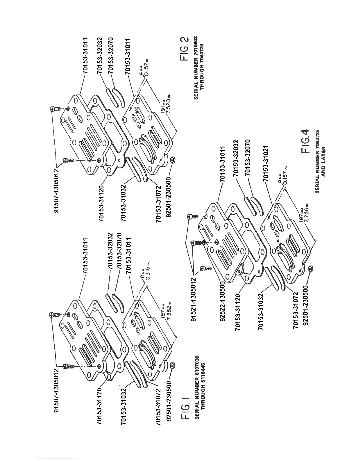
CAP-600
VALVE PLATES DESIGNS FOR E-57 COMPRESSOR
31

CAP-600
CM-FT.
TORQUE
INLET & OUTLET
VALVE PUSH COVERS
SIZE
BOLT
CM-FT.
TORQUE
100-6.8
100-6.8
100-6.8
180-13.0
180-13.0
180-18.0
225-16.3 225-16.3
M8-1.25
180-13.0
280-20.25
300-21.7
225-16.3 225-16.3
M8-1.25
M8-1.25
280-20.25
300-21.7
280-20.25
225-16.3
M8-1.25
M8-1.25
280-20.25
280-20.25
320-23.1
320-23.1
M10-1.5
M10-1.5
L
28-120.25
280-20.25
225-16.3
M8-1.25
H
REAR COVER
FRONT COVER
ROD BOLTS
SIZE
BOLT
CM-FT.
TORQUE
SIZE
BOLT
CM-FT.
TORQUE
SIZE
BOLT
CM-FT.
TORQUE
M6-1
100-6.8
M6-1
135-9.7
M6-1
M6-1
M6-1
100-6.8
180-13.0
M6-1
M8-1.25
135-9.7
180-13.0
M6-1
M8-1.25
120-8.7
200-14.5
M8-1.25
180-13.0
M8-1.25
180-13.0
M8-1.25
200-14.5
M8-1.25
180-13.0
M8-1.25
180-13.0
M8-1.25
200-14.5
M8-1.25
180-13.0
M8-1.25
180-13.0
M8-1.25
200-14.5
M8-1.25
180-13.0
M8-1.25
180-13.0
M8-1.25
200-14.5
M10-1.5
M8-1.25
180-13
280-20.25
M10-1.5
M8-1.25
180-13
280-20.25
M10-1.5
M8-1.25
200-14.5
280-20.25
M10-1.5
M10-1.5
280-20.25
280-20.25
M8-1.5
M8-1.5
280-20.25
280-20.25
M8-1.5
M8-1.5
280-20.25
280-20.25
M8-1.25
M10-1.5
300-21.7
300-21.7
M8-1.5
M10-1.5
300-21.7
280-20.25
M8-1.5
M8-1.25
280-20.25
280-20.25
M10-1.5
M10-1.5
300-21.7
320-23.11
M8-1.5
M10-1.5
300-21.7
320-23.1
M8-1.5
M10-1.5
350-25.3
280-20.25
M10-1.5
320-23.1
M10-1.5
320-23.1
M10-1.5
350-25.3
BOLT TORQUES FOR CHALLENGE AIR COMPRESSORS
CYLINDER-CASE
HEAD BOLTS
SIZE
BOLT
TORQUE
SIZE
BOLT
CM-FT.
120-8.7
M6-1
ES03
M8-1.25
200-14.5
M8-1.25
ES05
M6-1
120-8.7
M6-1
ES06
M8-14.5
200-14.5
M8-1.25
ES10
M8-1.25
200-14.5
M8-1.25
E11
M8-1.25
200-14.5
M8-1.25
ES20
32
M8-1.25
200-14.5
M8-1.25
E23
M10-1.5
M8-1.25
300-21.7
200-14.5
M10-1.5
M8-1.25
E35
ES30
M10-1.5
300-21.7
M10-1.5
ES50
M10-1.5
300-21.7
M10-1.5
E50
M10-1.5
320-23.1
M10-1.5
E57
M10-1.5
320-23.1
M10-1.5
ES100
M10-1.5
320-23.1
M10-1.5
E71
M10-1.75
320-23.1
M10-1.5
ES150
M10-1.75
320-23.1
M10-1.5
E15
CAP-600
BOLT TORQUES
MODEL
NO.
ES03 8 96 - ES05
ES06
ES10
E11
ES20
E23
E35
E57 23 276 - ES30 30 360 - -
FLYWHEEL BOLTS FAN BOLTS
TORQUE
FT.-LBS.
12 144 - -
TORQUE
IN.-LBS.
TORQUE
FT.-LBS.
TORQUE
IN.-LBS.
ES50
E50
E71
ES100
E15
ES150
40 480 - -
45 540 24 288
50 600 24 288
33

CAP-600
OIL CAPACITIES
MODEL
NUMBER
HORSEPOWER
ES03 1/4 – 1/2 500 1/2 PINTS
ES05 1/2 500 1/2 PINTS
ES06 3/4 500 10 OUNCES
ES10 1 500 1¼ PINTS
ES20 2 – 3 500 1¾ PINTS
ES30 3 – 5 500 1¼ PINTS
MIN
RPM
OIL CAPACITY
ES50 5 – 7½ 500 1½ QUARTS
ES100 7½ - 10 500 2½ QUARTS
ES150
ES150A
15 500 5 QUARTS
E11 1 500 1¼ PINTS
E23 2 – 3 500 1¾ PINTS
E35 3 – 5 500 2½ PINTS
E50 5 500 1½ QUARTS
E57 5 – 7½ 500 2 QUARTS
E71 10 500 2½ QUARTS
E15 15 500 5 QUARTS
34

TROUBLESHOOTING
Flywheel rotation in wrong direction Incorrect connection of motor terminal Re-arrange terminal connection.
Overheating of bearings 1. Insufficient lubrication.
Flywheel rotation slows down 1. Heavy lubrication oil.
Severe vibration Bent crankshaft Remove & Replace
Abnormal noise 1. Loose valve assembly.
WHEN COMPRESSOR CAN BE STARTED
Pressure cannot be built up or only
up to a certain extent
Inaccuracy of pressure gauge Pressure gauge damaged. Replace.
Excessive oil consumption 1. Worn piston ring
Slipping of belts 1. Working pressure too high.
Overheating of electric motors 1. Overloading of motor due to
CANNONT BE STARTED
Unit will not start 1. Breakdown of electric current.
WHEN COMPRESSOR
Fuse tends to blow 1. Incorrect size.
CURTIS-TOLEDO
SYMPTOMS CAUSES REMEDIES
1. Add lubrication oil.
2. Bad lubrication system.
3. Crankshaft bearings to tight.
2. Drop in voltage.
3. Belts slipping.
2. Piston hits cylinder cover.
3. Worn connecting rod bearing.
1. Worn valve plate.
2. Valve springs have lost their
temper.
3. Dirt on the valve plate.
4. Leaks from safety valve.
5. Leaks from bolt holes.
6. Uneven valve seat surface.
7. Excessive blow by on piston rings.
8. Bad packing (gasket to thick).
9. Excessive air leaks.
2. Worn piston.
3. Worn cylinder.
2. Improper belt tension.
3. Worn belt.
excessive working pressure
(higher than stipulated pressure).
2. Burnt piston.
3. Burnt bearing metals.
4. Drop of voltage.
2. Line failure.
3. Malfunction of motor
2. Wrong connections
3. Overloading of motor.
4. Overloading of motor due to leaks
of outlet valve.
5. Crankshaft too tight.
2. Remove and examine the system.
3. Readjust load on bearings.
1. Refill with lighter lubrication oil.
2. Contact power company or install
a transformer.
3. Tighten belts
1. Tighten valve bolt and lock nut.
2. Check piston & rod assembly for
excessive wear.
3. Replace bearing.
1. Repair or replace valve plate.
2. Replace valve springs.
3. Remove and clean it.
4. Repair or replace safety valve.
5. Tighten the nuts even with
packing.
6. Remove and lap the surface.
7. Replace with new ones
8. Replace packing (gasket).
9. Eliminate air leaks.
1. Replace.
2. Replace.
3. Replace.
1. Lower working pressure.
2. Adjust belt tension.
3. Replace with new ones.
1. Lower working pressure.
2. Rebuild compressor.
3. Rebuild compressor.
4. Contact power company or install
a transformer
1. Contact power company.
2. Examine the line. Replace with
new wiring.
3. Contact motor manufacturer.
1. Replace with correct size.
2. Change connections.
3. Eliminate the loading.
4. Remove and repair outlet valve.
5. Remove crankshaft and examine
it for cause.
CUSTOMER SERVICE (314) 383-1300
CAP-600
35

CAP-600
RECOMMENDED STATEMENT ON DRYERS AND FILTERS
Liquid water occurs naturally in air lines as a result of compression. Moisture
vapor in ambient air is concentrated when pressurized and condenses when cooled in
downstream air piping.
Compressed air dryers reduce water vapor concentration and prevent liquid
water formation in compressed air lines. Dryers are necessary companion to air filters,
aftercoolers, and automatic tank drains for improving the productivity of compressed air
systems.
Water and water vapor removal increases the efficiency of air operated
equipment, reduces contamination and rusting, increases service life of pneumatic
equipment and tools, prevents air line freeze ups, and reduces product rejects. The use
of dryer’s filters is recommended when this moisture related problems are reported to
our factory or distributor service departments.
Troubleshooting guide
Symptom: Liquid water present in compressed air lines.
Problem: Water vapor condensation from cooling and
compression occurs naturally
Solution: Remove the water vapor from compressed air prior to
distribution through the air system. Check operation of
after-cooler and moisture separator. Install a compressed
air dryer sized for the flow and dryness level required.
(Note: filters may also be required to remove
particles, liquid oil aerosols, or for oil vapor removal.
Change cartridges as recommended by filter manufacturer.)
Check all drain traps routinely to insure their proper operation.
Maintain them regularly.
36

TWO STAGE
H.P.
Size
3 3VT6 947 10.66 20 x 50 60 12’ – 24” 2’ – 8”
5 5E23VT6 1000 11.3 20 x 50 60 11’ – 47” 2’ – 1”
5 5E1HT6 1100 15.81 20 x 50 60 7’ – 46” 1’ – 20”
5 5E1VT6 1100 15.81 20 x 50 60 7’ – 46” 1’ – 20”
5 5E1HT8 1100 15.81 20 x 48 80 10’ – 21” 1’ – 46”
5 5E1VT8 1100 15.81 20 x 48 80 10’ – 21” 1’ – 46”
5 5HT6 968 20.58 20 x 50 60 5’ – 56” 1’ – 1”
5 5VT6 968 20.58 20 x 50 60 5’ – 56” 1’ – 1”
5 5HT8 968 20.58 20 x 66 80 7’ – 54” 1’ – 21”
5 5VT8 968 20.58 20 x 48 80 7’ – 54” 1’ – 21”
5 5E2HT6 900 21.47 20 x 50 60 5’ – 25” 0’ – 56”
5 5E2VT6 900 21.47 20 x 50 60 5’ – 25” 0’ – 56”
5 5E2HT8 900 21.47 20 x 66 80 7’ – 14” 1’ – 14”
5 5E2VT8 900 21.47 20 x 48 80 7’ – 14” 1’ – 14”
7 1/2 7E2HT8 1100 26.24 20 x 66 80 6’ – 16” 1’ – 05”
7 1/2 7E2VT8 1100 26.24 24 x 48 80 6’ – 16” 1’ – 05”
7 1/2 7HT8 764 29.57 20 x 66 80 5’ – 22” 0’ – 55”
10 10HT8 977 37.81 20 x 66 80 4’ – 11” 0’ – 43”
10 10HT12 977 37.81 24 x 70 120 6’ – 17” 1’ – 5”
10 10VT12 977 37.81 30 x 47 120 6’ – 17” 1’ – 5”
15 15HT12 855 54.55 24 x 70 120 4’ – 28” 0’ – 46”
TWO STAGE
H.P.
Size
COMPRESSOR PUMP-UP TIME
Compressor
Model No. R.P.M.
GASOLINE ENGINE DRIVEN
Compressor
Model No. R.P.M.
Piston
Displ.
C.F.M.
Piston
Displ.
C.F.M.
Tank size Approx. Time Required
Size
(in)
Tank size Approx. Time Required
Size
(in)
Gal
Gal
0 to 175 PSIG
0 to 175 PSIG
To Pump From:
Min. – Sec.
To Pump From:
Min. – Sec.
CAP-600
145 to 175 PSIG
Min. – Sec.
145 to 175 PSIG
Min. – Sec.
10 10E2GT3 910 21.7 16 x 41 30 2’ – 42” 0’ – 28”
10 10GT3 950 20.2 16 x 41 30 3’ – 1” 0’ – 31”
10 10GT6 950 20.2 20 x 50 60 6’ – 3” 1’ – 2”
13 13E2GT3K 910 21.7 16 x 41 30 2’ – 42” 0’ – 28”
13 13GT3K 950 20.2 16 x 41 30 3’ – 1” 0’ – 31”
13 13GTGK 950 20.2 20 x 50 60 6’ – 3” 1’ – 2”
13 13E2GT3HE 910 21.7 16 x 41 30 2’ – 42” 0’ – 28”
37

SINGLE STAGE
H.P.
Size
3 3HS6 945 15.97 20 x 50 60 6’ – 16” 1’ – 15”
3 3VS6 945 15.97 20 x 50 60 6’ – 16” 1’ – 15”
5 5ES20VS6 1000 16.9 20 x 50 60 6’ – 4” 1’ – 13”
5 5HS6 945 20.13 20 x 50 60 4’ – 8” 0’ – 50”
5 5VS6 945 20.13 20 x 50 60 4’ – 8” 0’ – 50”
5 5HS6 945 20.13 20 x 66 80 5’ – 31” 1’ – 6”
5 5VS8 945 20.13 24 x 48 80 5’ – 31” 1’ – 6”
7 1/2 7HS8 945 30.14 20 x 66 80 3’ – 35” 0’ – 43”
7 1/2 7VS8 945 30.14 24 x 48 80 3’ – 35” 0’ – 43”
10 10HS8 866 50.4 20 x 66 80 2’ – 7” 0’ – 25”
10 10HS12 866 50.4 24 x 70 120 3’ – 10” 0’ – 38”
10 10VS12 866 50.4 30 x 47 120 3’ – 10” 0’ – 38”
15 15HS12 855 81.74 24 x 70 120 2’ – 2” 0’ – 24”
COMPRESSOR PUMP-UP TIME
Compressor
Model No. R.P.M.
Piston
Displ.
C.F.M.
Tank size Approx. Time Required
Size
(in)
Gal
0 to 100 PSIG
To Pump From:
Min. – Sec.
CAP-600
80 to 100 PSIG
Min. – Sec.
38

NOTES
39
CAP-600

CURTIS – TOLEDO, INC.
1905 KIENLEN AVE., ST. LOUIS, MO 63133
TEL. (314) 383-1300 FAX (314) 381-1439
E-MAIL: info@curtistoledo.com
www.curtistoledo.com
 Loading...