

Page 1

Page 2

Data Center, Enterprise & ISP Network Solutions
2
CONTENTS
Chapter Ⅰ Overview
Chapter Ⅱ Features
2.1 Product Introduction
2.2 Product Specifications
Chapter Ⅲ Hardware Description
3.1 Front Panel
3.2 Mainboard
..................................................................................................................................................................
...................................................................................................................................................................
.................................................................................................................................................
..................................................................................................................................................
................................................................................................................................................
..............................................................................................................................................
.....................................................................................................................
Chapter Ⅳ Controller Module Installation
4.1 CPU Installation
4.2 CPU Heatsink Installation
4.3 Memory Installation
4.4 PIKE Card and Expansion Card Installation
.......................................................................................................................................................
......................................................................................................................................
................................................................................................................................................
.......................................................................................................
.................................................................................................
3
4
4
5
6
6
8
25
25
29
30
32
Chapter Ⅴ Chassis Installation
5.1 Backplane and SPIB Board Installation
5.2 Fan Installation
5.3 Controller Module Installation
5.4 Hard Disk Installation
.........................................................................................................................................................
.............................................................................................................................................
.........................................................................................................................
..............................................................................................................
.............................................................................................................................
Chapter Ⅵ System Cabinet Installation
6.1 Overview
6.2 Rail Mounting
....................................................................................................................................................................
...........................................................................................................................................................
.......................................................................................................
34
34
36
37
38
40
40
40
Page 3

Data Center, Enterprise & ISP Network Solutions
3
Chapter
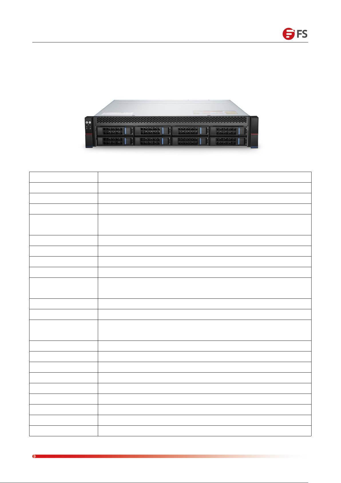
RS-6388 Server is a 2U low-power, controller-architecture storage product suitable for large data
storage, cloud storage, video surveillance network storage, and NAS storage.
Benefit from platform flexibility and maximize performance with Intel® Xeon® processors for
enterprise customer, RS-6388 Server provides a high performance and storage capacity for
future growth. It supports 2 ECC DDR4 DIMMs with 32GB of memory capacity. Utilizing the
Intel® PCHLynx point C232 series chipset, it is well suited for ERP (Enterprise Resource Planning)
and mail service. With RAS (Reliability, Availability, Serviceability) features, it is also an excellent
choice for SMB solution.
Ⅰ
Overview
Figure 1-1 Appearance
Page 4

Data Center, Enterprise & ISP Network Solutions
4
Support Intel® Xeon® processor to drive applications faster
Support the memory capacity 32GB with 2x DIMM slots and high-performance DDR4 memory
Accelerate data throughput with 1 x PCI expansion slots
High scalability through various expansion devices such as 1GbE network cards and low-power
Enhance storage options with 9TB, 3x 3.5‘’ SATA3.0 drives
The cableless design in motherboard to strengthen the heat dissipation of components
Optimize the operational efficiency with a high compatibility
Hot-plug redundant fans and power supplies
High quality electronic components and Low power consumption
Chapter
Ⅱ
Features
2.1 Product Introduction
FS.COM 2U 1-socket rack server has high performance storage flexibility, it is a great choice that
the basic configuration options are available for SMB deployments. RS-6388 Server hardware
provides high-availability features, this server has a great cooling system for a balance between
performance and power efficiency, and it can maximum computing power with low power
consumption.
Maximize Application Performance in SMB
grade GPUs
Flexibility and Versatility Design
Perfect Hardware Design
Page 5
Data Center, Enterprise & ISP Network Solutions
5
CPU Type
Intel® Xeon® Pocessor E3-1200 v5
Memory Capacity
32GB
Drives
9TB, 3x 3.5” SATA3.0
Dimensions
2U rack mount, 19.68” x 17.63” x 3.46” (D x W x H)
CPU
Intel® Xeon® Processor E3-1200 v5/v6 series
Intel® 6th/7th Generation Core i3/i5/i7 series
Memory
Up to 64GB ECC DDR4-1600/1866/2133 UDIMM
DIMM Slot Quantity
4x 288pin DDR4 DIMM slots
Drive Bays
Support 8x 3.5” (2.5” compatible) SAS 3.0/ SATA 3.0 HDDs
Chipset
Intel® PCH Lynx point C232 chipset
PCIe Devices
Expansion
Support 2x PCIe x8 swap SATA Drives
Build-in RAID
Intel® RSTe Support software RAID 0, 1, 5 & 10 (for Windows only)
BMC
Aspeed AST2400
IPMI
1x Share-able IPMI Management GbE Port
Default with one PMC8068 or LSI 3008 Mezzanine SAS Card
Network
4x Intel®i210-AT 1GbE LAN controller
USB
2x USB3.0 on Rear and 2x Internal USB3.0 ports
M.2
Support 1x PCIe M.2 SSD or SATA M.2 SSD, 2242/2280
PSU Module
Two 1+1 CRPS 550W 80+ Platinum Redundant PSU Modules
PSU Input/Output
AC Input: 100-240V 47Hz~63Hz; DC Output: +12V_SB, +12V
Fan Quantity
Up to 4 x 8038, support PWM smart fan control
Fan Speed
Maximum 6800RPM
Humidity
OP: 35%~80%; NON-OP: 20% ~ 90%
Temperature
OP: 10ºC ~ 35ºC; NON-OP: -40ºC ~ 70ºC
2.2 Product Specifications
Page 6
Data Center, Enterprise & ISP Network Solutions
6
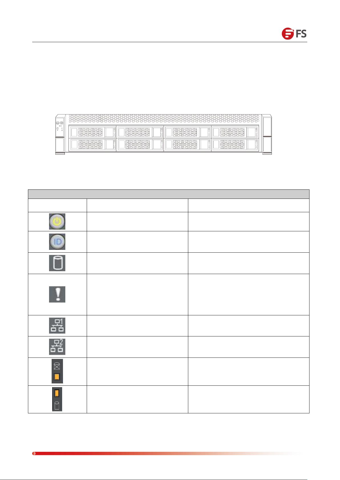
The above figure shows the LED indicators of each module on the front panel, which is
LED Status Description
Image
LED Appearance
Description
Green light is on
Device startup
Blue light is always on
ID indicator
Green light flashes
Operating normally
Yellow light is always on
Alarm indicator, including system alarm,
fan alarm, power alarm, etc., which can
be viewed through IPMI management
software.
Green light is on
Network port 1 is connected properly
Green light is on
Network port 2 is connected properly
Blue light is always on
Yellow light is always on
Hard disk position indication
Hard disk alarm indication
Green light is on
Hard disk is in place
Chapter Ⅲ Hardware Description
3.1 Front Panel
described in the following table:
Page 7
Data Center, Enterprise & ISP Network Solutions
7
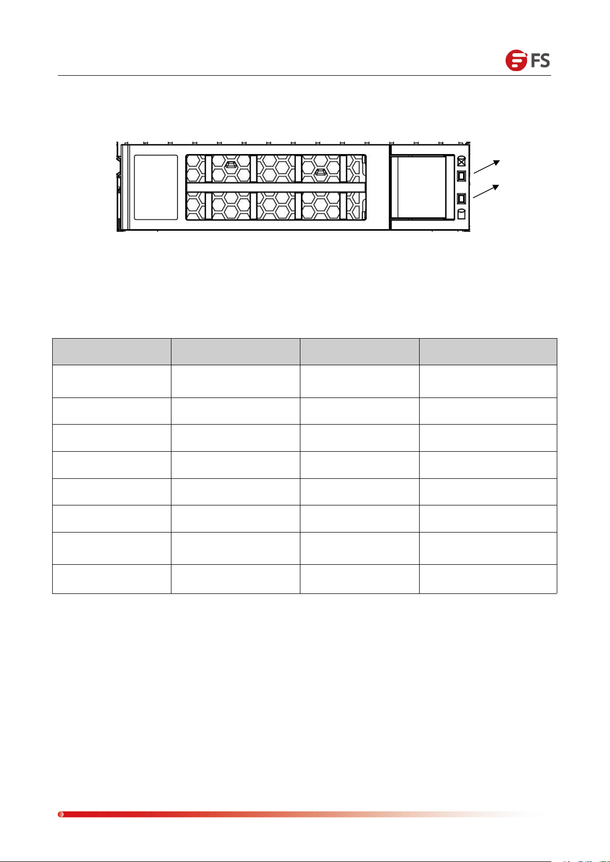
Hard Disk Indicators
Features
Green light
Blue light
Yellow light
Hard disk does not
exist
OFF
OFF
OFF
Hard disk exists
LIGHT ON
OFF
OFF
Hard disk activity
Flashing 4Hz/s
OFF
OFF
Hard disk positioning
LIGHT ON
Flashing
OFF
Hard disk failure
LIGHT ON
OFF
LIGHT ON
Offline
LIGHT ON
OFF
OFF
RAID reconstruction
The entire array flashes
at 4Hz/s
OFF
Hot spare flashes
1Hz/second
Hot Standby
LIGHT ON
OFF
OFF
Act LED
(1) Status LED (green light)
(2) Act LED (blue light, yellow light)
(3) LED description as shown below:
Page 8
Data Center, Enterprise & ISP Network Solutions
8
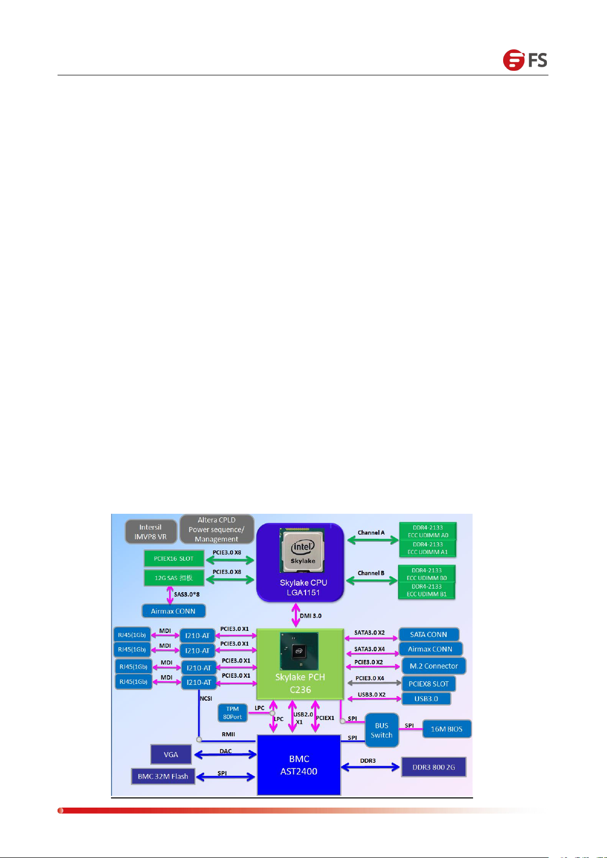
Controller system uses Intel Greenlow platform, with LGA1151 CPU, support Celeron
System memory consists of 4 Dual Channel DIMMs which support up to 64GB ECC
Chipset uses Intel PCH C232.
The controller module supports two 2.5-inch SATA HDDs or SSDs and also supports a
The system adopts 550W1+1 redundant white gold brand efficiency power supply and
The system uses 4 easy-swapping 8038 fans.
The system uses two Intel I210-AT RJ45 Gigabit Ethernet ports.
The system has an independent IPMI management network port for remote
The system has a VGA port derived from the BMC.
The system has two USB3.0 interfaces for users.
3.2 Mainboard
The mainboard features are as follows:
series, Pentium series, Intel 6th Generation Core i3/i5/i7 series, Intel Xeon Processor
E3-1200 V5 series, maximum support 84W.
UDIMMs.
half-height PCIe card.
supports hot swapping and replacement.
management. The BMC chip uses Aspeed AST2400.
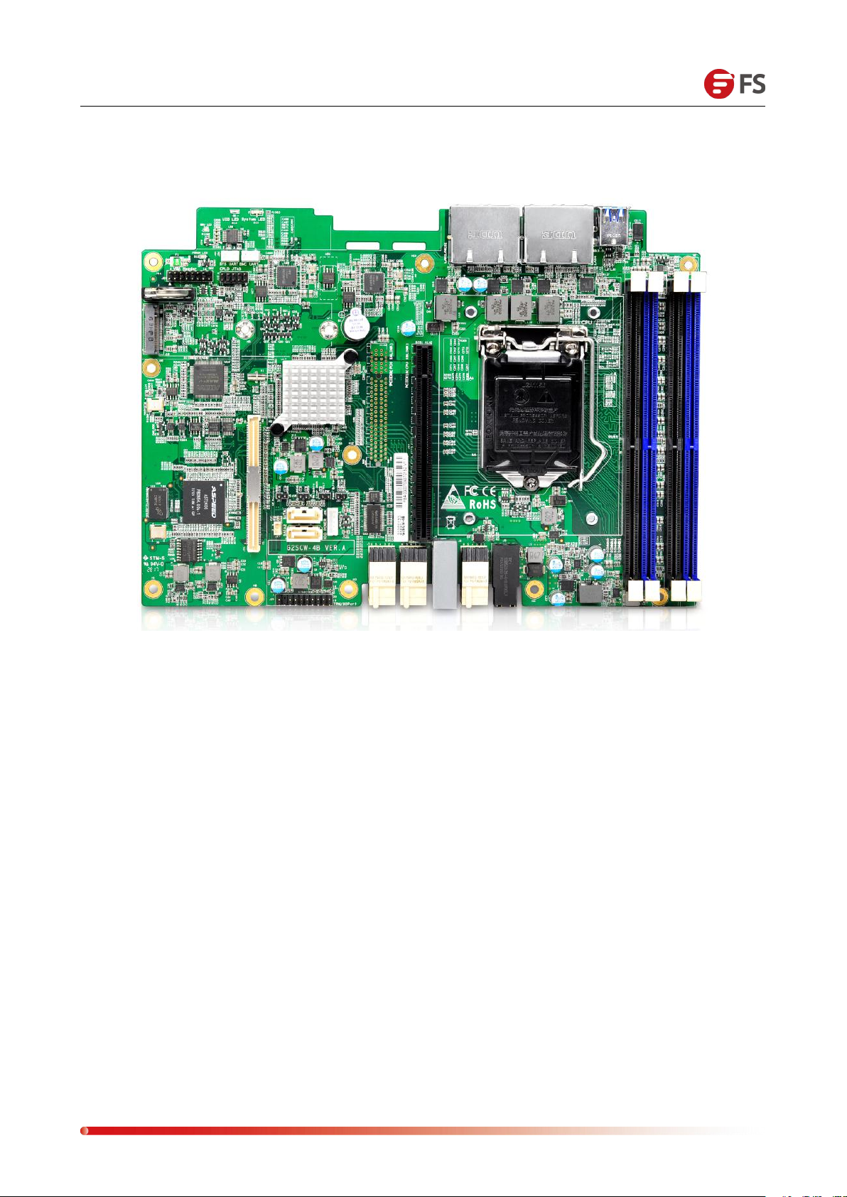
The system architecture board diagram is as follows:
Page 9
Data Center, Enterprise & ISP Network Solutions
9
Overview
Page 10
Data Center, Enterprise & ISP Network Solutions
10
I/O Interfaces
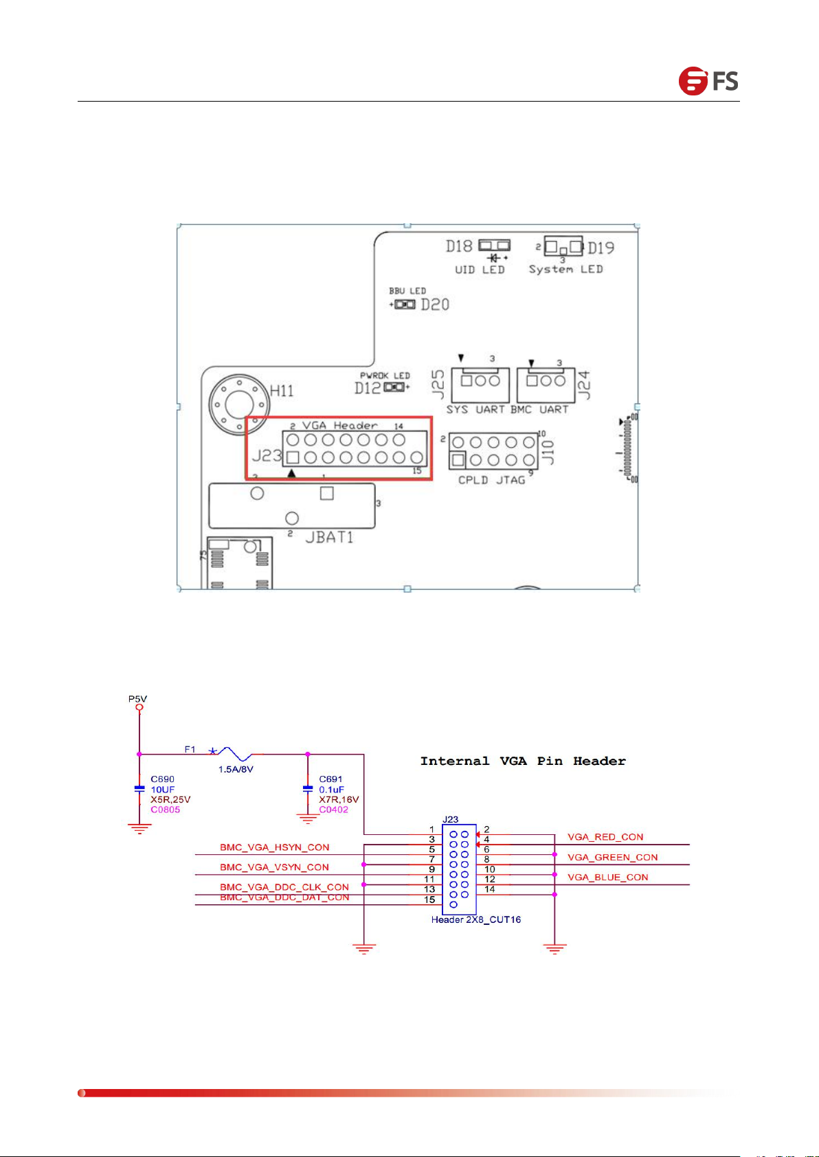
VGA connector position and Pin definition:
Page 11
Data Center, Enterprise & ISP Network Solutions
11
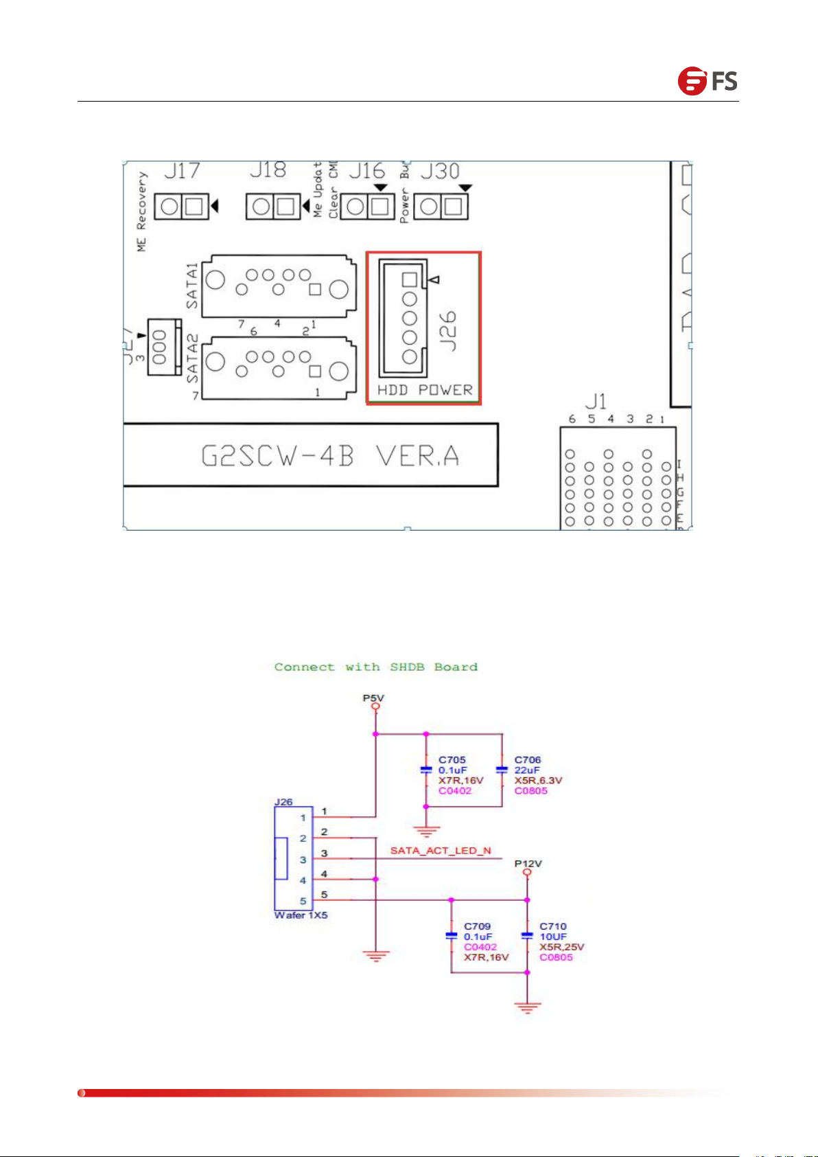
HDD Power Connector Location and PIN Definition:
Page 12
Data Center, Enterprise & ISP Network Solutions
12
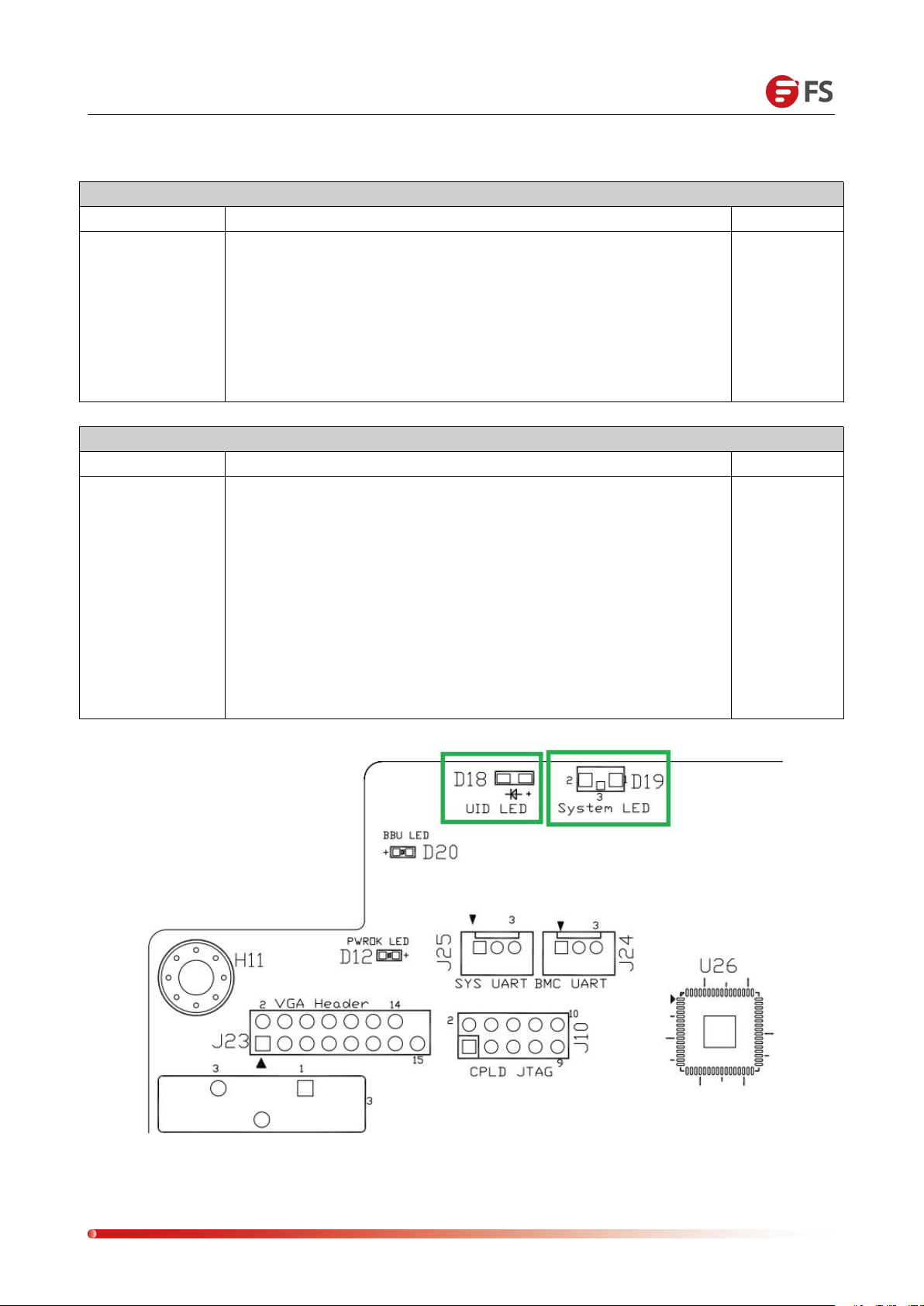
UID LED
Description
Location
BLUE LED
The UID LED is a user-defined indicator that is used to indicate a
specific motherboard. The IPMI can be used to remotely control
the web interface to turn the LED on or off. For example, when a
server is found an error by remote management and needs to
be maintained, it can mark the problem board with UID LED on
the web, then you can find the motherboard. After maintenance,
turn off the UID LED.
D18
(Front)
System LED
Description
Location
YELLOW/
GREEN LED
System LED is used to indicate the current status of the system,
with PWRBTN function.
The LED status is as follows:
Green Light on, the system status is normal.
Green is 1HZ flashing, the system has CPU, but it is not on, it is in
standby state.
Yellow Light on, the system has detected a fault
(overheat/fan/power failure/alarm)
No light, AC is not powered, or AC powered but there is no
CPU/BMC; not working.
D19
(Front)
In-board LED Definition and Description:
Page 13
Data Center, Enterprise & ISP Network Solutions
13
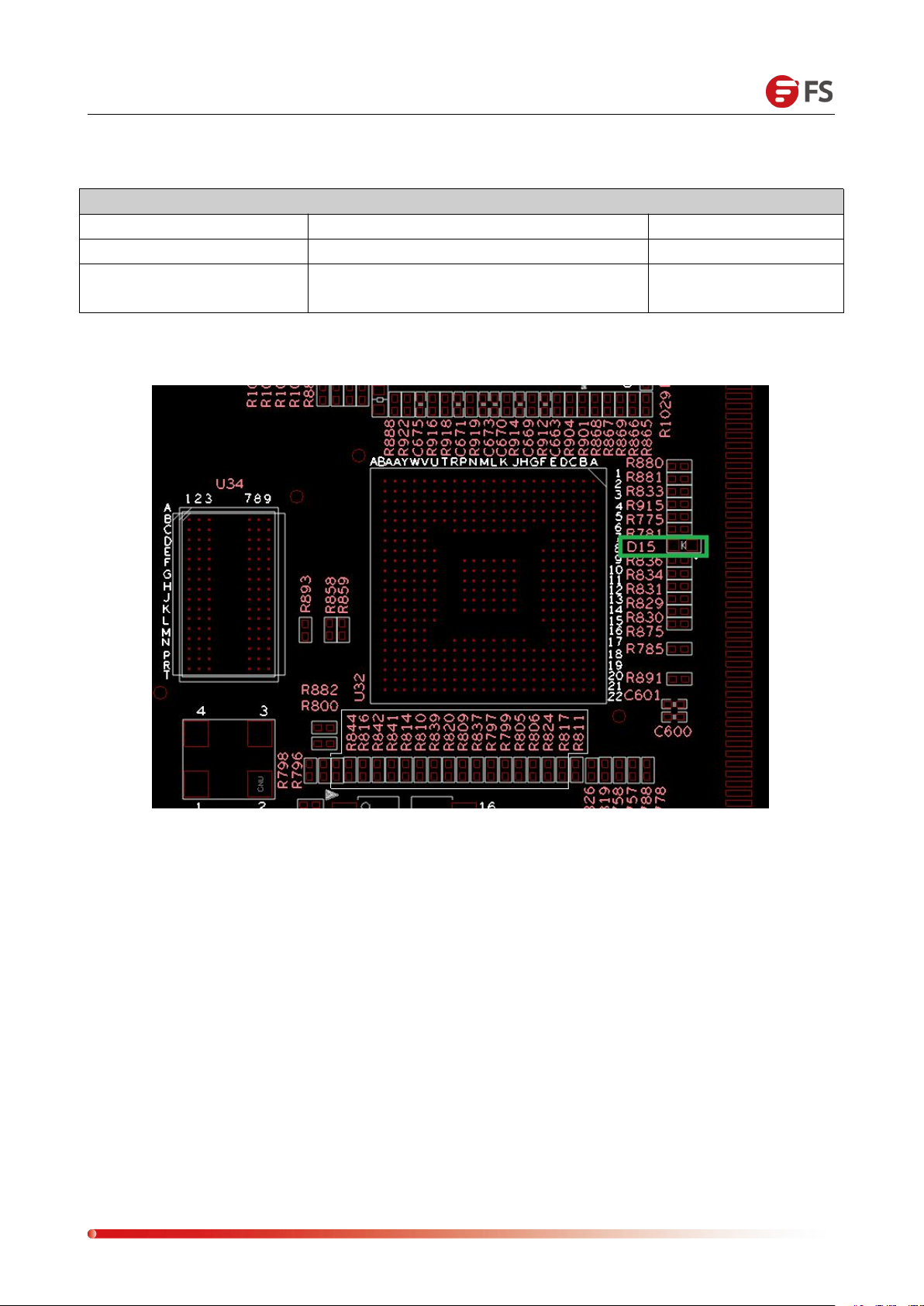
BMC Heart LED
Description
Location
Firmware initialization is OK
The green indicator light flashes at 1HZ
D15
Firmware initialization is
not completed
This indicator is not lit
BMC Heart-beat LED
Page 14

Data Center, Enterprise & ISP Network Solutions
14
BBU LED
Description
Location
BBU Green LED
BBU LED: Indicates BBU status
Steady green: The BBU is charging normally. The
system is ready for BBU at any time.
Green flashes at 1HZ: Switched to BBU, BBU is
supplying power
Green is off: the BBU is not installed or the BBU is not
charging.
D20
In-board PWROK LED
Description
Location
In-board power supply is
OK
Green LED is always on
D12
In-board power supply is
not OK
Green LED is off
In-board CPLD Heartbeat LED
Description
Location
CPLD program is normal
Green LED flashes at 1HZ
D7
CPLD has not been
programmed or abnormal
Green LED is off
BBU LED/PWROK LED/CPLD LED:
Page 15
Data Center, Enterprise & ISP Network Solutions
15
LAN Port LED
Description
Note
Left LED
Link status indicator:
1. Gigabit Link, green light on;
2. 100M Link, orange light on;
3. Ten mega Link, the LED is off.
Right LED
Active status indicator:
When there is active data, the yellow light flashes;
This indicator does not light when there is no data.
LAN Port LED:
Page 16
Data Center, Enterprise & ISP Network Solutions
16
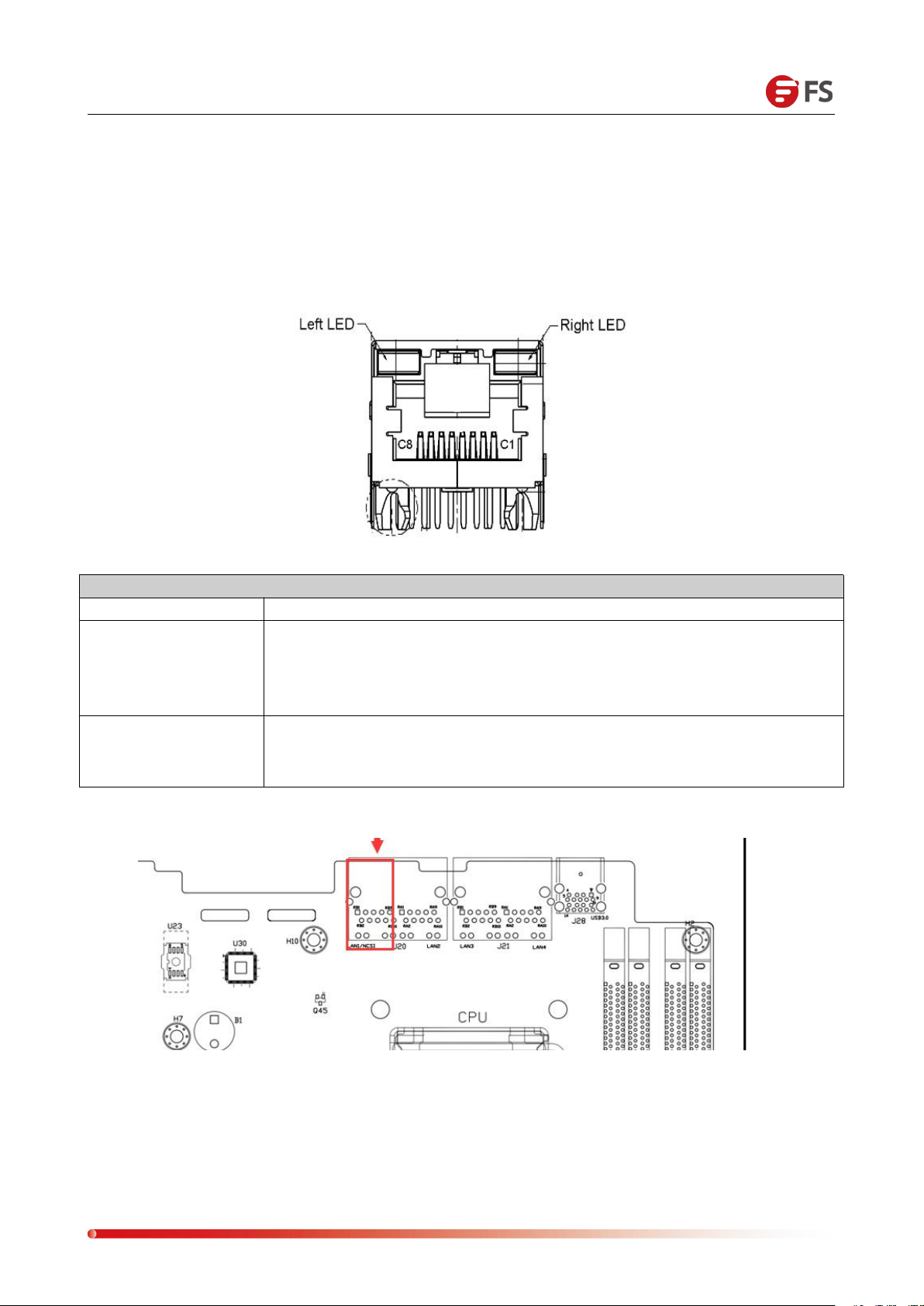
IPMI LAN Port LED
Description
Left LED
Link status indicator:
1. Gigabit Link, green light on;
2. 100M Link, orange light on;
3. Ten mega Link, the LED is off.
Right LED
Active status indicator:
When there is active data, the yellow light flashes;
This indicator does not light when there is no data.
IPMI LAN Port
The network port is dedicated to IPMI ( J20 location), used for IPMI remote management, connected
to the switch with CAT5 and above cables, or directly connected to the client's host. It supports
Gigabit, 100M, and adaptive adjustment, but it cannot be used as a service data network port. The
LED indicators of this network port are as follows:
Location:
Page 17
Data Center, Enterprise & ISP Network Solutions
17
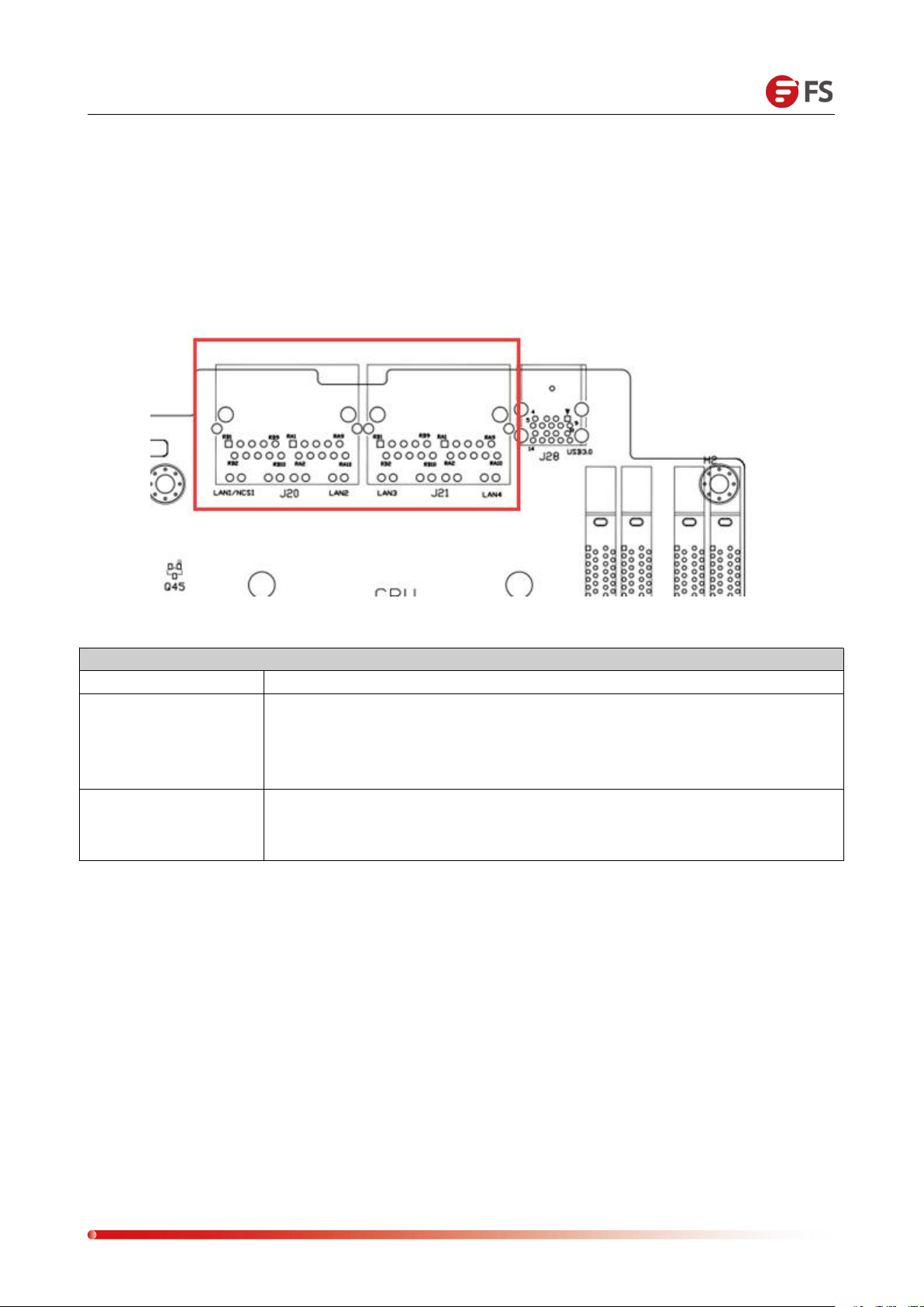
LAN Port LED
Description
Left LED
Link status indicator:
1. Gigabit Link, green light on;
2. 100M Link, orange light on;
3. Ten mega Link, the LED is off.
Right LED
Active status indicator:
When there is active data, the yellow light flashes;
This indicator does not light when there is no data.
LAN Port
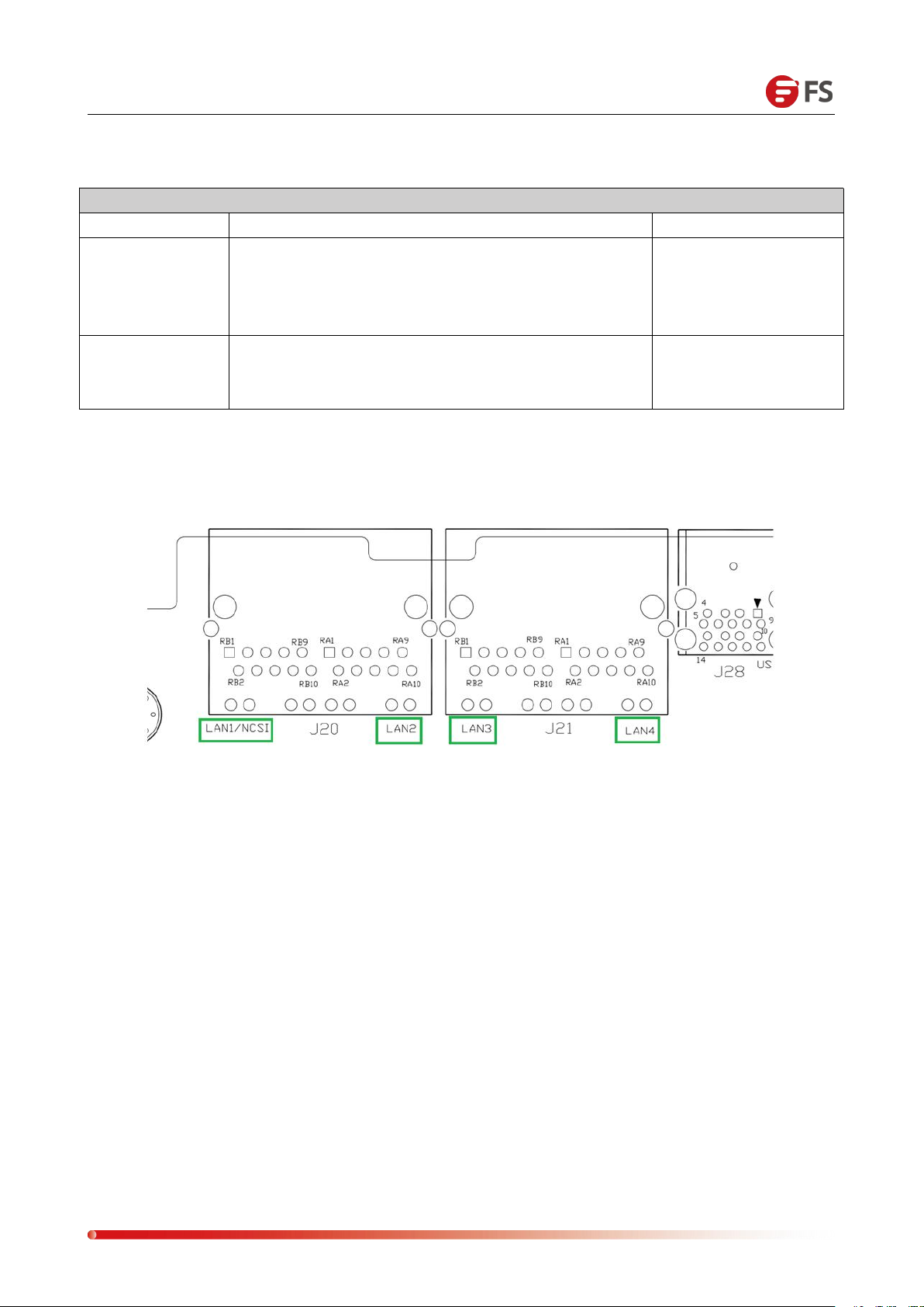
The mainboard provides two Gigabit Ethernet ports (J20/21), the main chip adopts Intel I210-AT,
adaptive 1000M, 100M, 10M. The mainboard has four Gigabit service LAN ports for
receiving/sending business data, using CAT5 and above cables access switch can also be directly
connected to the client's host. The LED indicators of LAN portS are as follows:
Page 18
Data Center, Enterprise & ISP Network Solutions
18
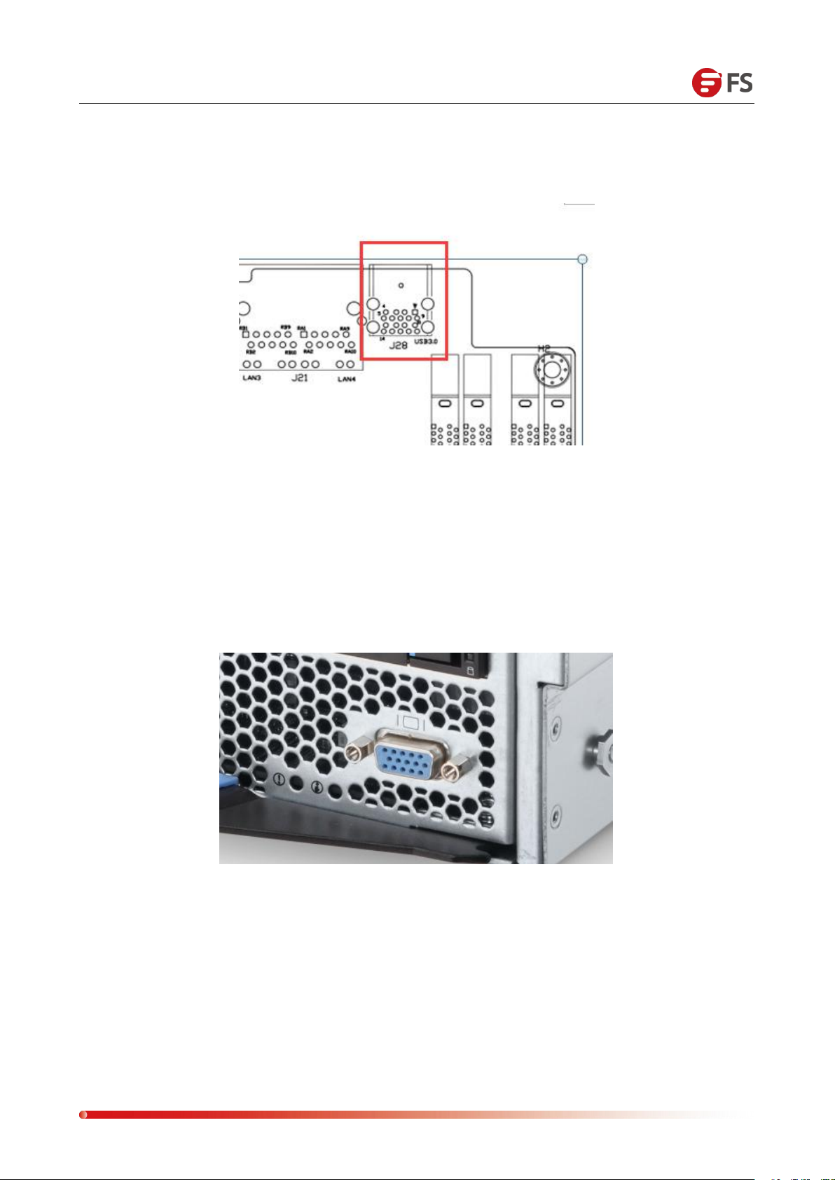
USB Interface
2 USB 3.0 ports (J28):
VGA Interface
The mainboard's graphics chip uses AST2400, AST2400 built-in PCIE VGA Controller, a 15PIN VGA
Connector is used to access the VGA display, output host information, the location diagram is as
follows:
Page 19
Data Center, Enterprise & ISP Network Solutions
19
SATA Connector PIN Definition
PIN Number
Description
PIN1
Ground
PIN2
SATA HOST TX+
PIN3
SATA HOST TX-
PIN4
Ground
PIN5
SATA HOST RX-
PIN6
SATA HOST RX+
PIN7
Ground
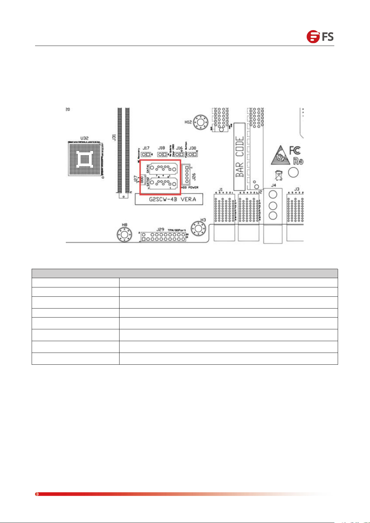
SATA Interface
The mainboard has 2 SATA 3.0 Connectors, all from Intel PCH. This system comes standard with
C232 PCH chip.
Page 20
Data Center, Enterprise & ISP Network Solutions
20
SATA DOM POWER Connector PIN Definition
PIN Number
Description
PIN1
5V
PIN2
Ground
PIN3
Ground
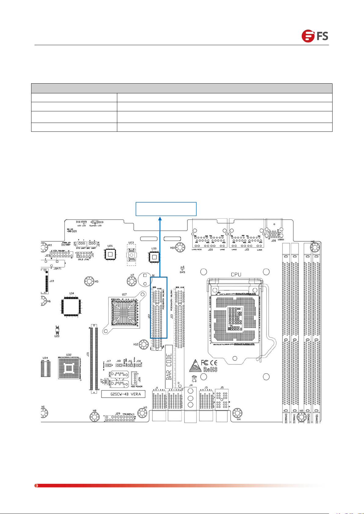
PCIe 3.0 X8 Slot
SATA DOM POWER CONNECTOR (J27)
The mainboard has 3 PIN Power Connectors for SATA DOM access to the power supply.
Introduction to PCIe 3.0 X8
The motherboard has a built-in PCIe 3.0 X8 Slot (J13). The standard PCIe X8 board can be inserted
with the PCIE Slot signal as the standard signal.
Page 21
Data Center, Enterprise & ISP Network Solutions
21
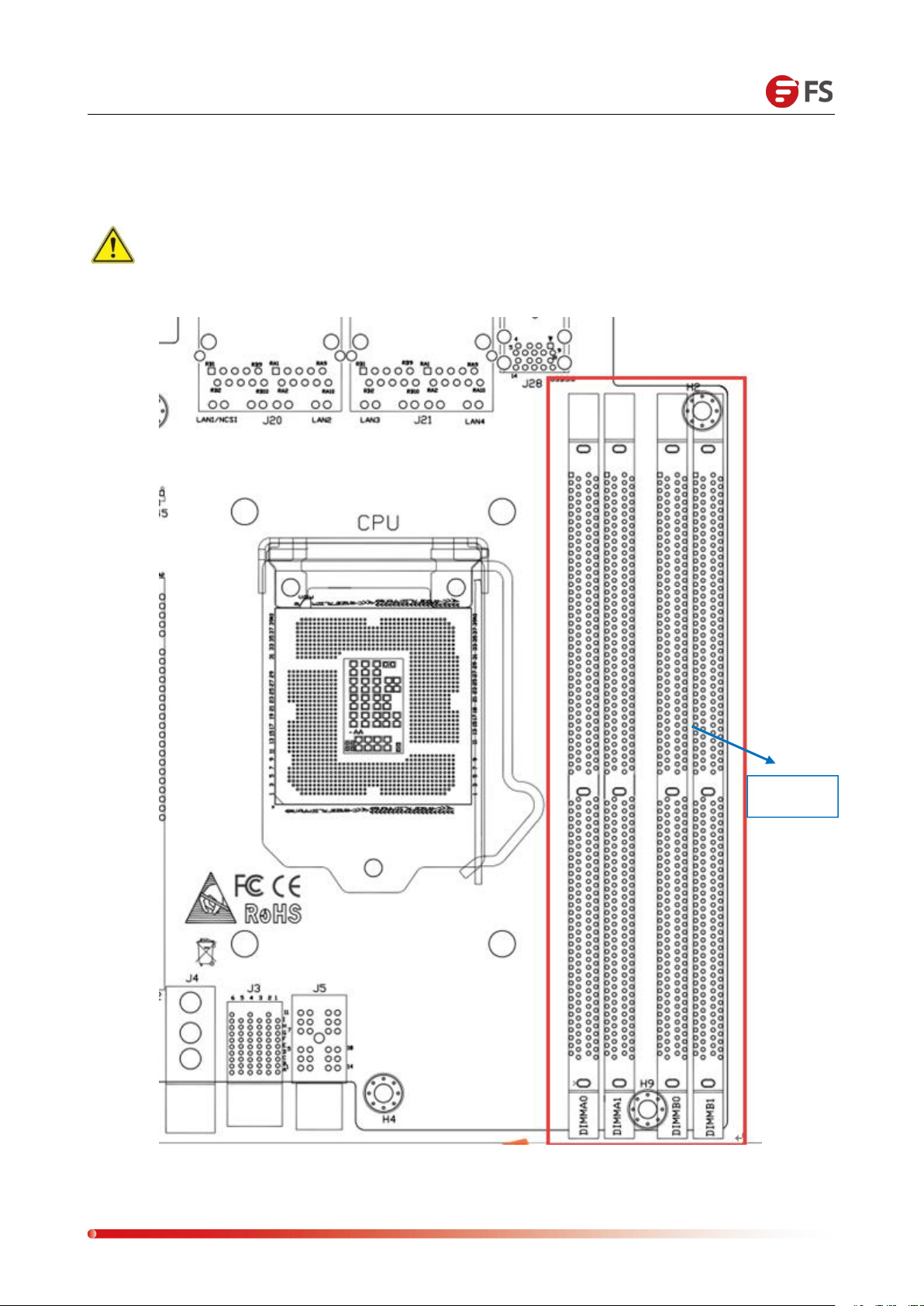
DDR4 Slot
Introduction to DIMM SLOT
The mainboard has four DDR4 slots, divided into Channel A, Channel B. Each channel has two
DIMM slots.
Note: If only one DIMM strip is inserted into each Channel, it needs to be inserted into
the slot away from the CPU.
Page 22
Data Center, Enterprise & ISP Network Solutions
22
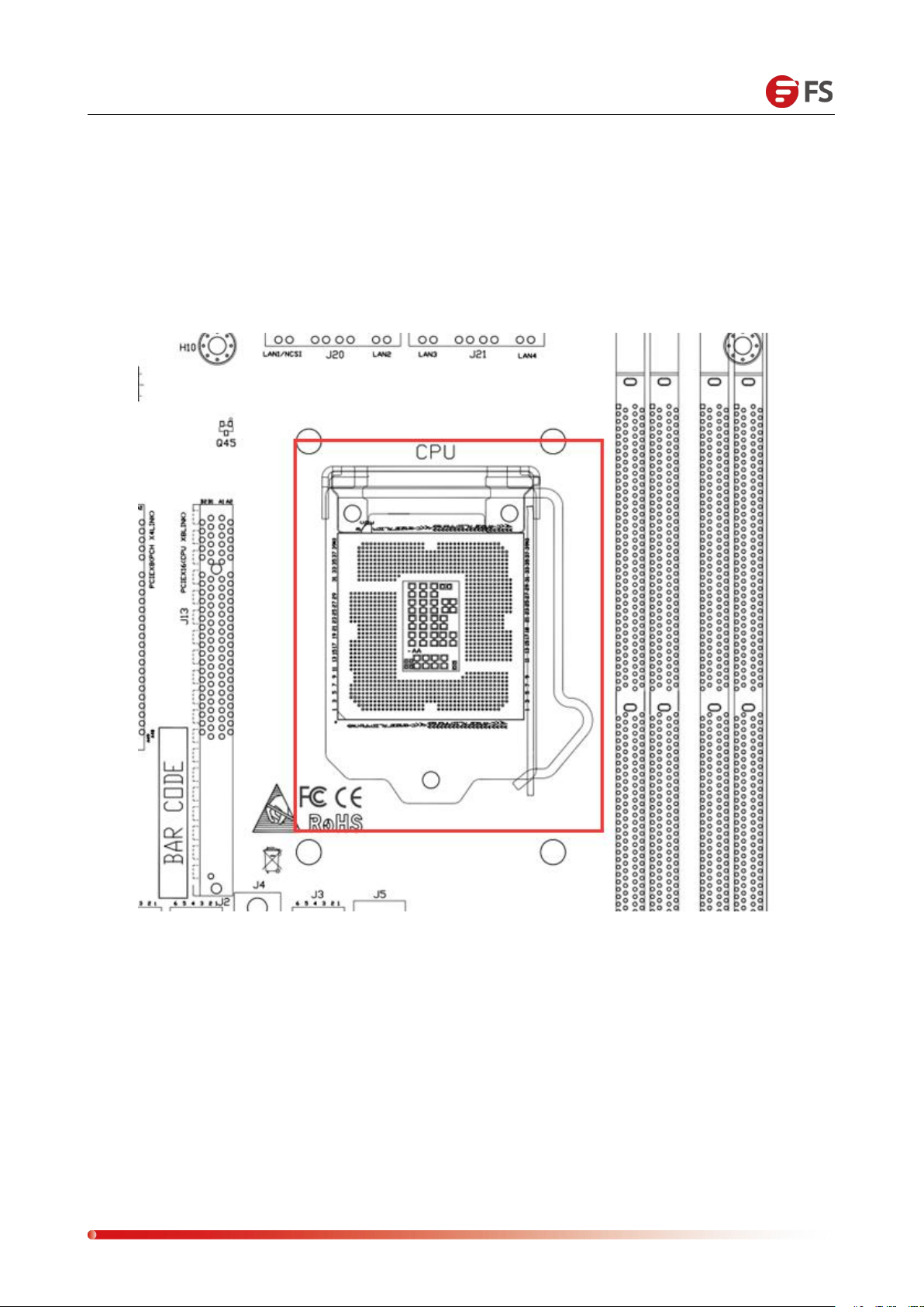
Introduction to CPU SOCKET
LGA1151 CPU SOCKET is the CPU used to load the LGA1151. During the CPU installation, you need
to pay attention to the installation of the first PIN. The first PIN is shown below. As indicated by the
triangular arrow, it is a triangular arrow corresponding to the CPU.
Page 23
Data Center, Enterprise & ISP Network Solutions
23
Power Module
LED
Description
GREEN ON
The power module is operating normally
ORANGE ON
Power module alarm, may over temperature, over voltage, over current, or
fan failure
OFF
AC power is not connected to the power module
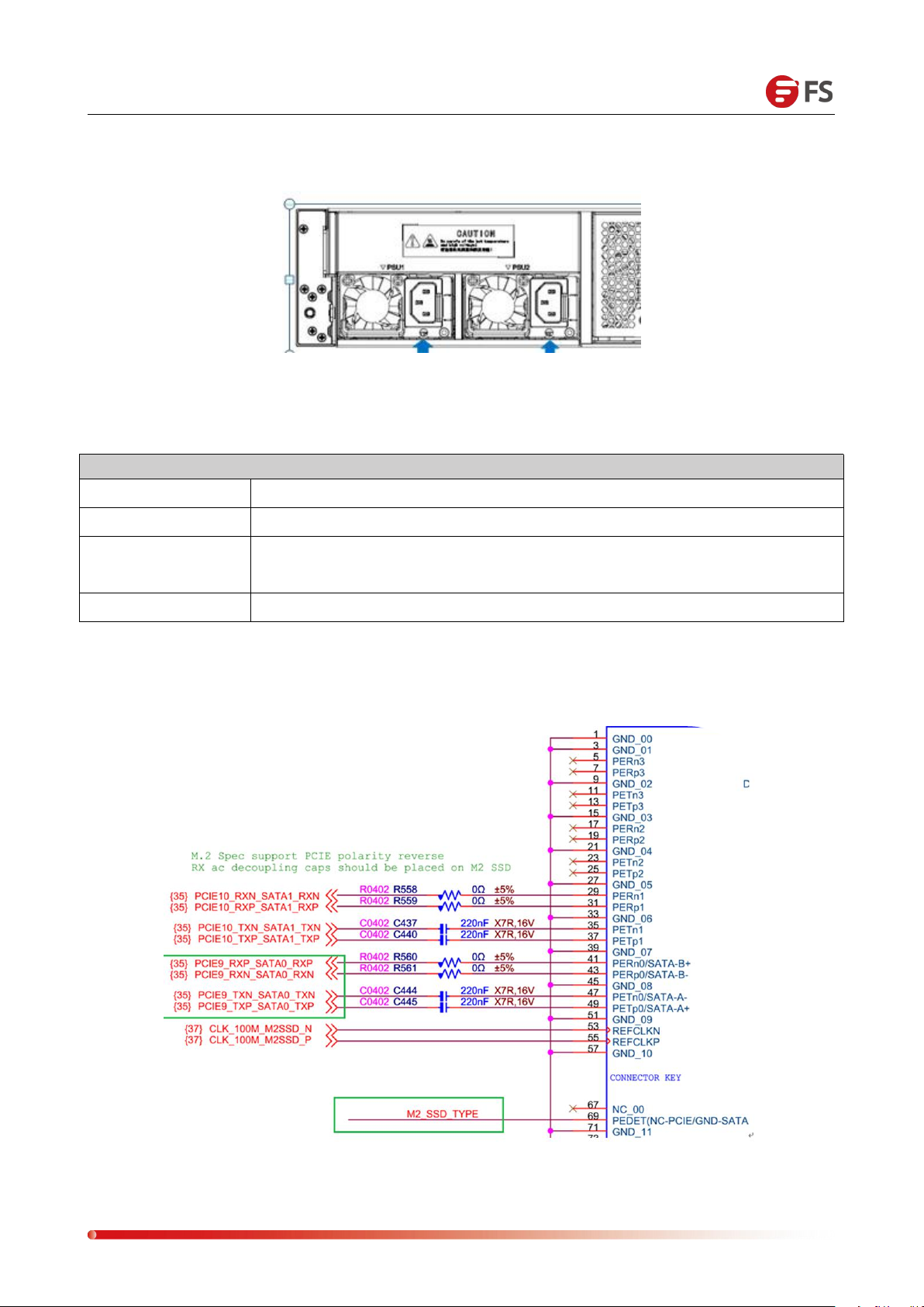
75Pin M.2 SSD Connector with PCIe X2 and SATA Specification Adaptive SSD
The arrows in the above figure are labeled as the LED indicators of the power module. Each power
module has its own LED indication, as described in the following table:
Page 24
Data Center, Enterprise & ISP Network Solutions
24
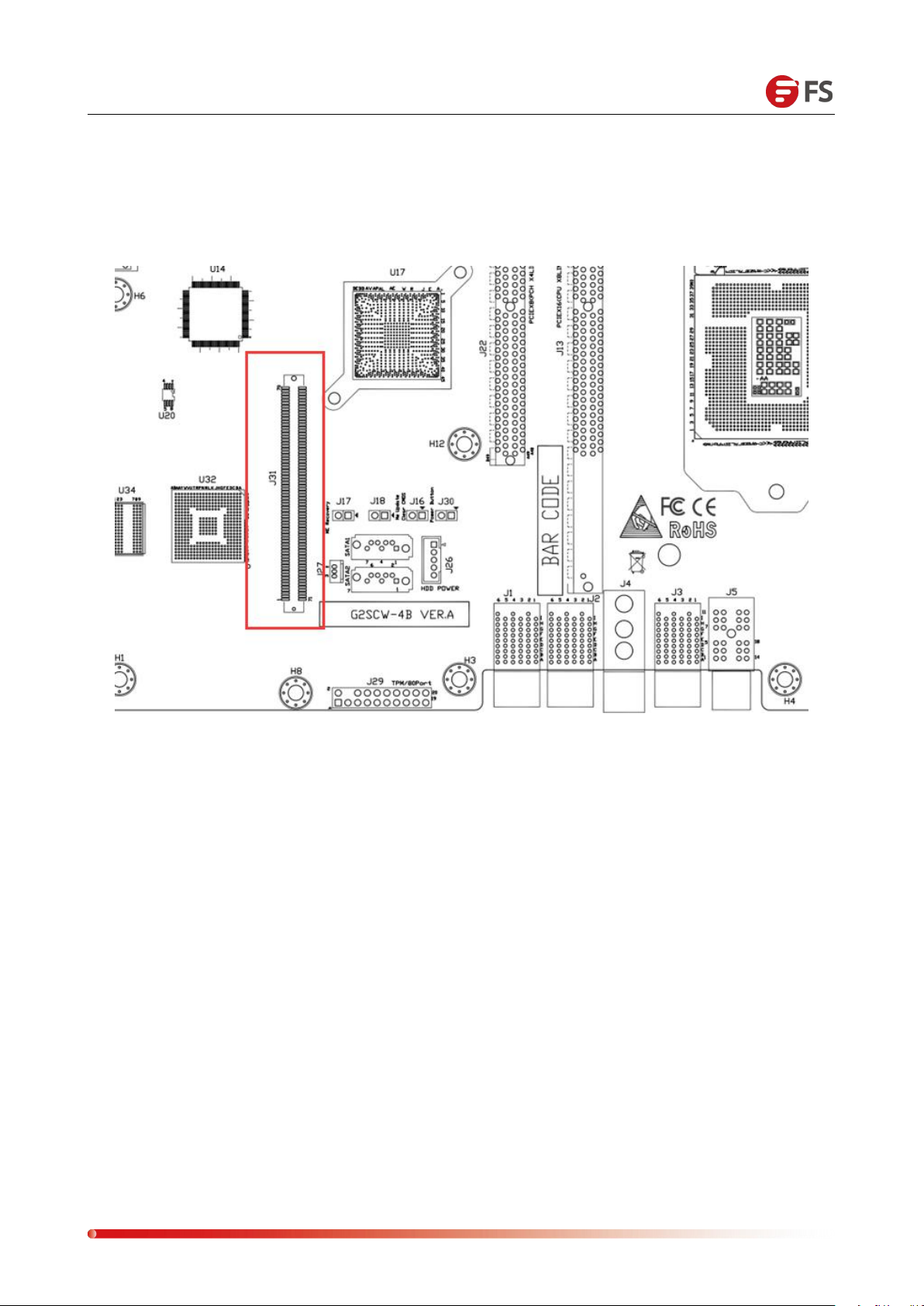
Expansion slot (Mezzanine), Mezzanine connector, Buckle plate connector connects to PCIe
X8 signal, used to insert PMC G8068M or LSI SAS3008 SAS12G Card, the position is as follows
(J31):
Page 25
Data Center, Enterprise & ISP Network Solutions
25
1. Please purchase Intel CPU through formal channels.
2. Please make sure that the purchased processor specifications belong to this
Chapter
Ⅳ
Controller Module Installation
4.1 CPU Installation
CAUTION:
system's support type.
Page 26
Data Center, Enterprise & ISP Network Solutions
26
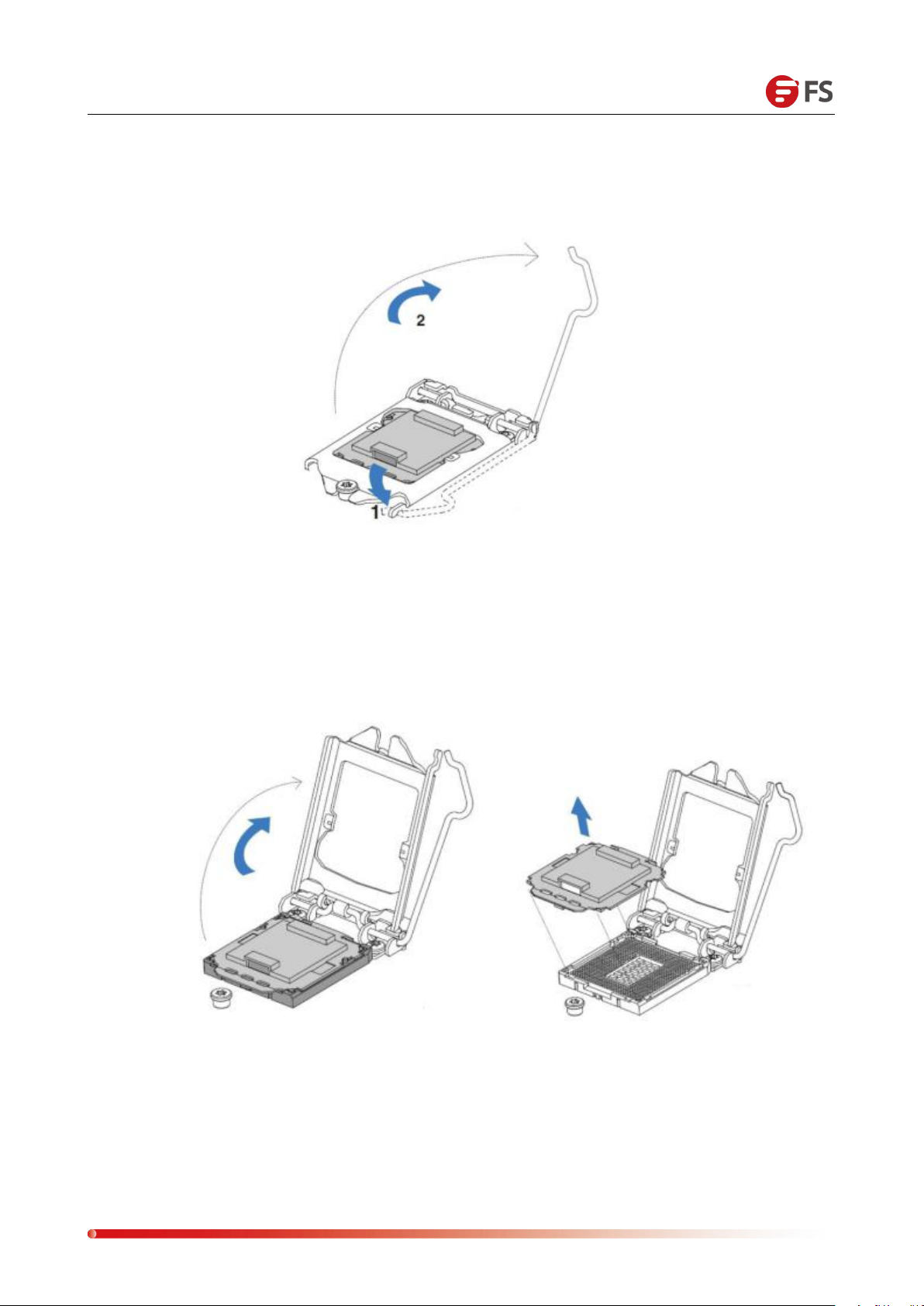
Detailed installation of LGA1151 processor steps:
1. Press gently on the platen and push outwards (to the right) to unlock.
2. Once the pressure plate handle is unlocked, gently lift the handle to open the pressure plate.
Page 27
Data Center, Enterprise & ISP Network Solutions
27
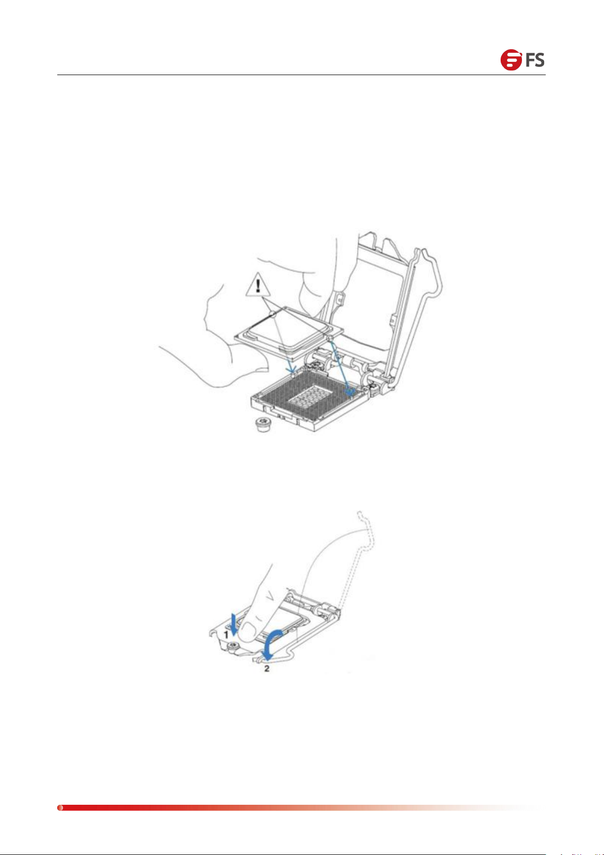
3. Once the load board is open, use your thumb and forefinger to pinch the north central edge of
the CPU and the south central edge of the CPU, hold the processor with your thumb and forefinger,
and make sure that the socket's alignment point is aligned with the processor's gap. Place the
processor straight into the slot, do not lean or slide, and gently release the processor to ensure it is
properly seated in the socket.
4. No force is required to close the load plate. Press down the load plate, close and hold the slot
lever.
Page 28
Data Center, Enterprise & ISP Network Solutions
28
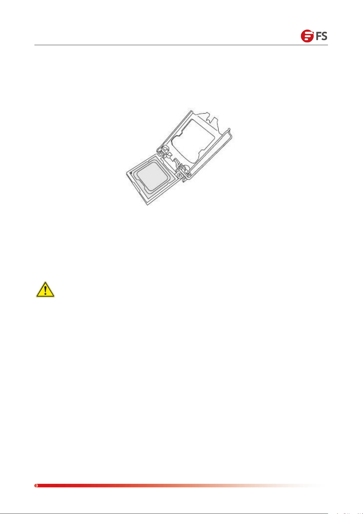
5. Once they are aligned, carefully insert the CPU straight down into the slot. (To avoid damage to
the CPU or socket, do not rub the surface of the CPU or any pin sockets.)
For the CPU in place in the socket, check the four corners of the CPU to ensure correct installation.
Warning:
You can install the CPU inside the socket only in one direction to make sure it is plugged into
the CPU socket correctly before closing the load board. If it does not close properly, do not
force it, as this may damage your CPU; instead, check that the CPU is properly aligned and
securely seated in the socket before opening the platen.
Page 29
Data Center, Enterprise & ISP Network Solutions
29
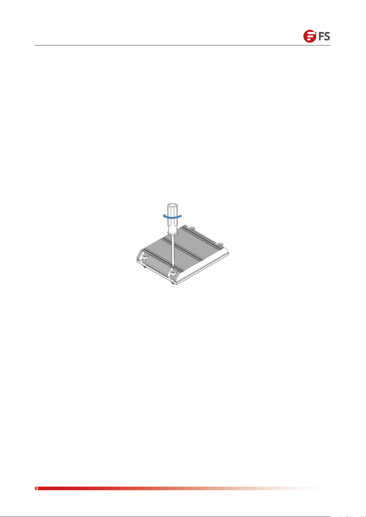
1. Remove the heat sink and apply the appropriate amount of hot silicone paste to the bottom of
2.
Place the heat sink on top of the CPU so that the four mounting holes are aligned with the
3. First tighten the two diagonal screws until they are just in place (to avoid damage to the CPU
4. Tighten the four bolts fully to complete the installation.
5.
Reverse the sequence of this process to remove the heat sink.
4.2 CPU Heatsink Installation
the heat sink.
motherboard and the lower heat sink bracket.
and heat sink, do not overtighten the screws).
Page 30
Data Center, Enterprise & ISP Network Solutions
30
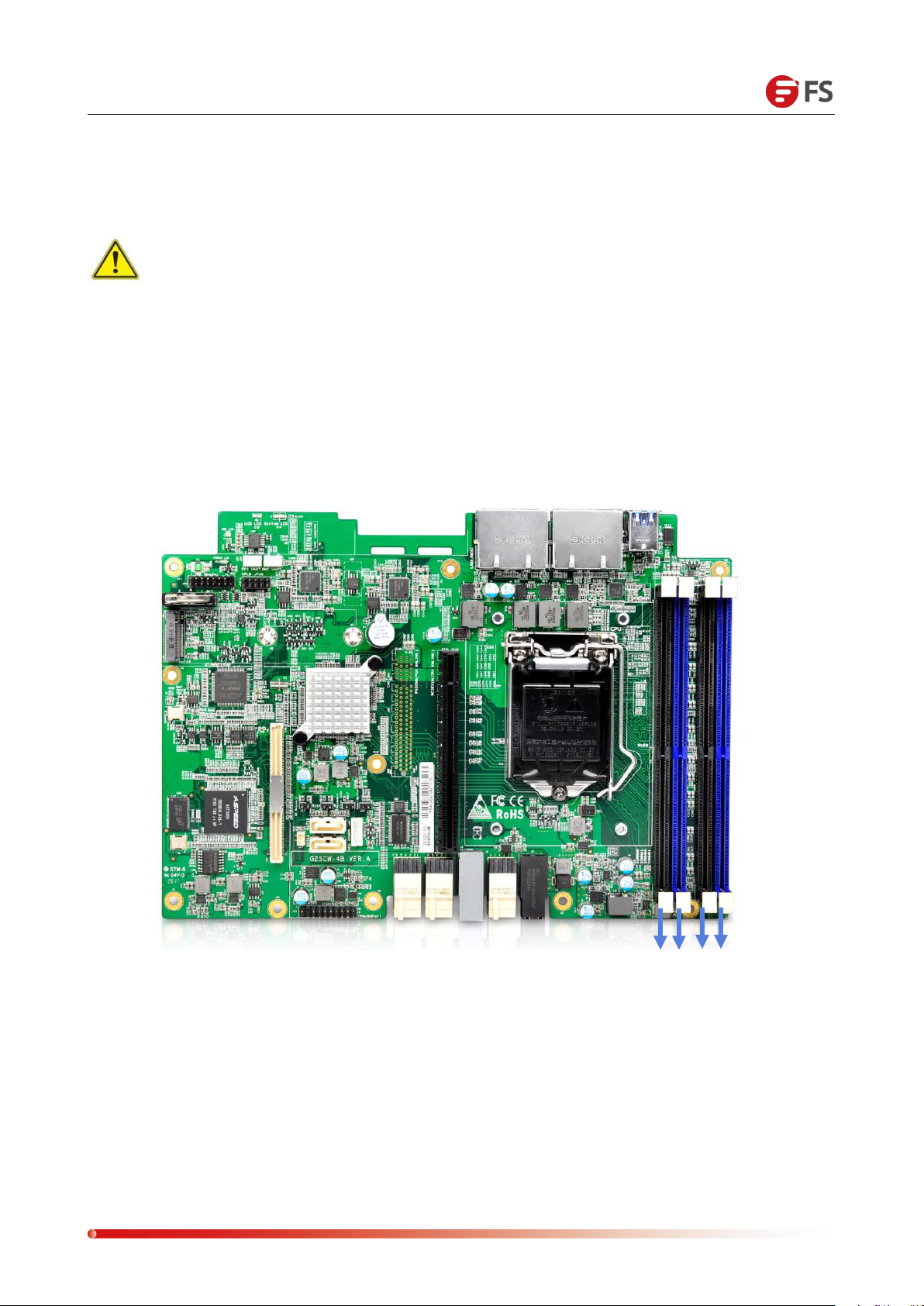
HOW TO INSTALL MEMORY
1. Motherboard DIMM slot sequence: DIMMA0, DIMMB0, DIMMA1, and DIMMB1, pay attention
2. Vertically snap each DIMM module into place.
MEMORY SUPPORT SPECIFICATIONS
DIMMB1
DIMMB0
DIMMA1
4.3 Memory Installation
Note: When installing or removing DIMMs, prevent any possible damage to DIMMs or
their respective slots.
to the memory of the hole and the DIMM slot gap to prevent incorrect installation.
The motherboard supports up to 1066/1333/1600 MHz of ECC DDR3 64GB memory. There are four
DIMM slots and use the same size, type, and speed of DDR3 memory modules. The board will support
the installation of one, two, or four DIMM modules, and for the best memory performance it needs to
be installed in the same color slot as the DIMM.
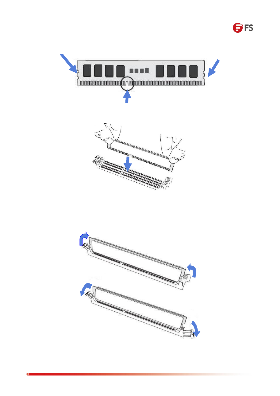
Installation: Insert the memory module vertically and press the memory slot snap-in position. Note the
bottom of the alignment notch.
Page 31
Data Center, Enterprise & ISP Network Solutions
31
GAP
NOTCH
Simulate the demo diagram inserted into the memory bar:
Removal: Use your thumb to gently push the release tab near both ends of the memory module
socket to release the memory from the socket.
Simulate the demo picture of disassembling the memory:
Page 32
Data Center, Enterprise & ISP Network Solutions
32
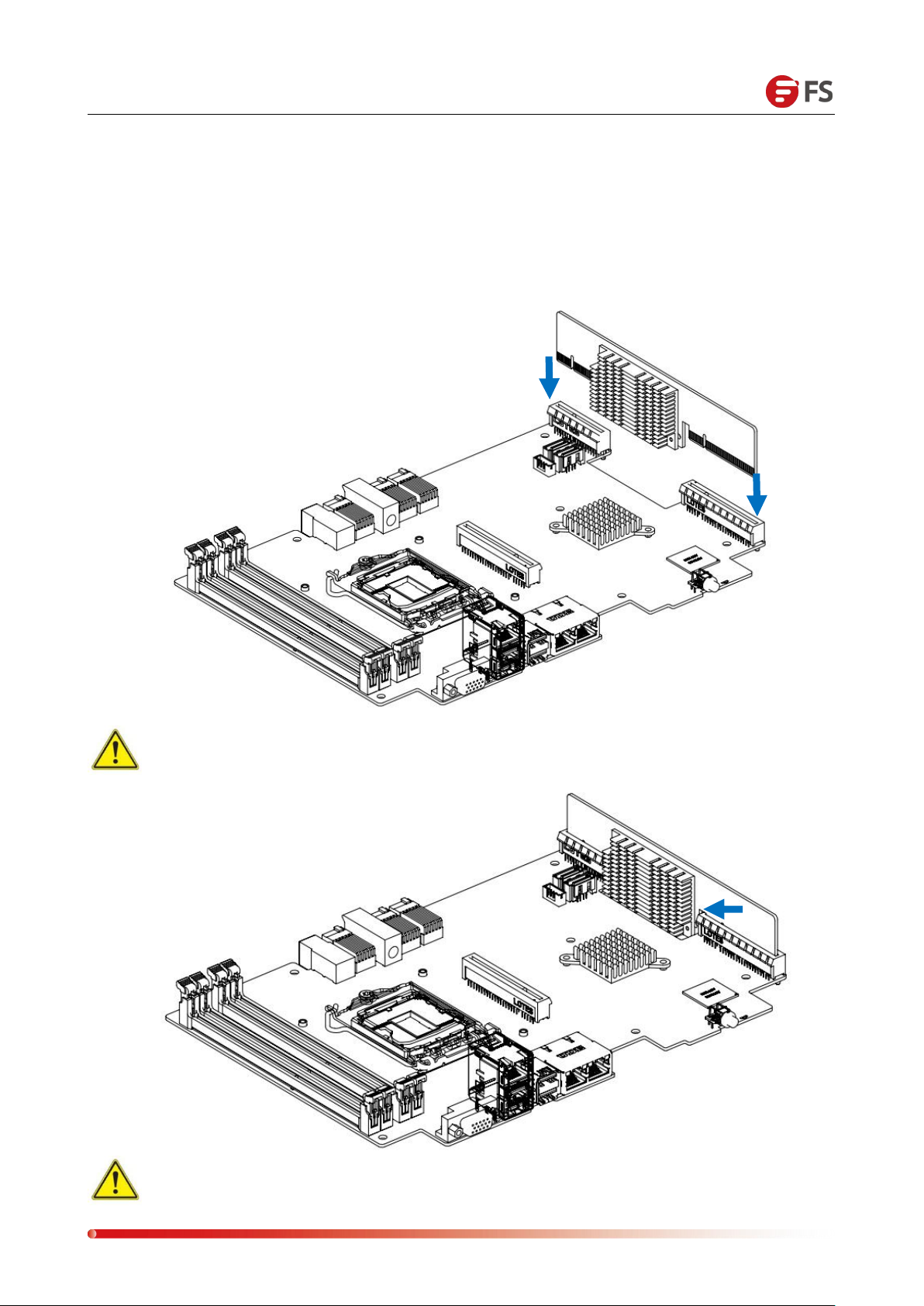
4.4 PIKE Card and Expansion Card Installation
The system controller module comes standard with the LSI SAS2008 chipset PIKE card and also
supports the expansion of a half-height PCIE expansion card.
PIKE card installation as shown below:
Note: Align the groove, and press it firmly on both sides at the same time.
Note: Make sure the PIKE card is in place.
Page 33
Data Center, Enterprise & ISP Network Solutions
33
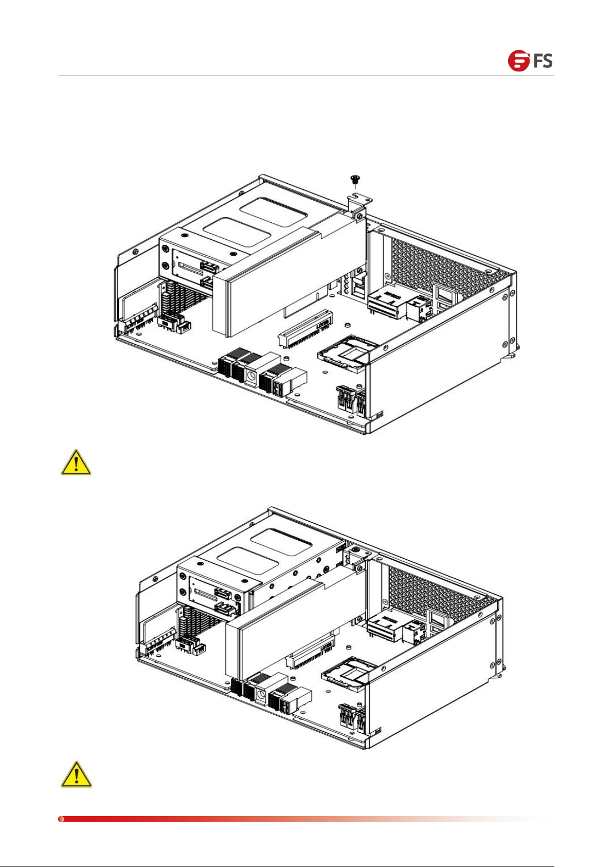
Installing a PCIe Expansion Card:
Install the expansion card to the PCIe expansion card and secure it to the bracket with screws.
The schematic diagram is as follows:
Note: Pay attention to balance force during installation, and ensure that the
expansion card is inserted into the motherboard vertically.
Note: Make sure the PCIE expansion card is in place and lock the screw.
Page 34
Data Center, Enterprise & ISP Network Solutions
34
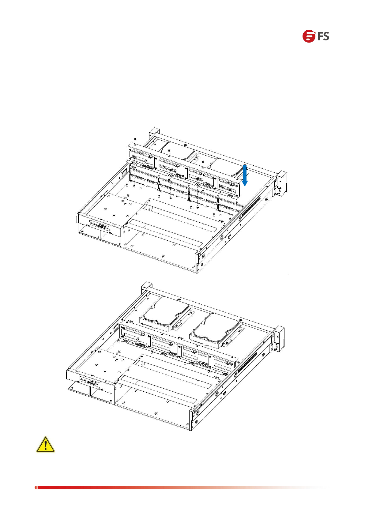
Chapter Ⅴ Chassis Installation
5.1 Backplane and SPIB Board Installation
Installation diagram of the backplane is as follows:
Note: Make sure that the backboard is inserted vertically, and fix the fixing screws on
three sides
Page 35
Data Center, Enterprise & ISP Network Solutions
35
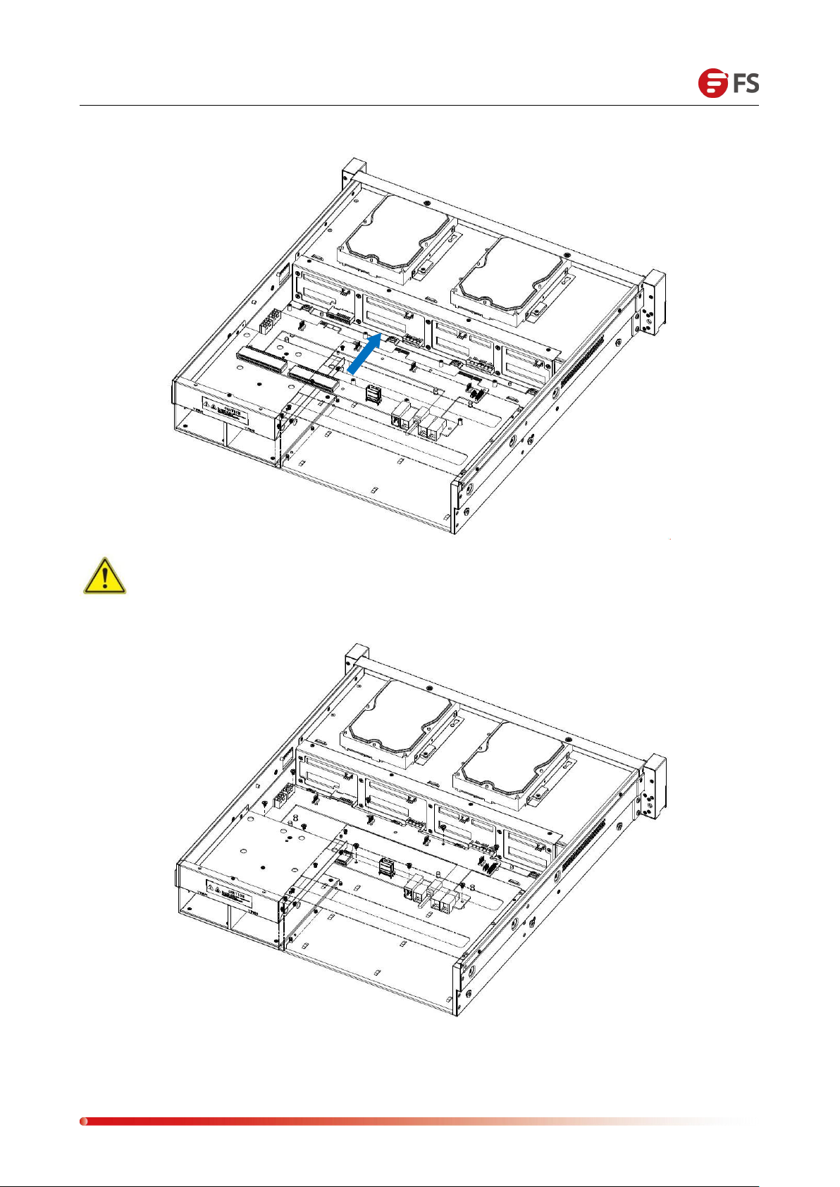
The schematic diagram of installing the SPIB board is as follows:
Note: When installing or removing the SPIB board, please pay attention to the
components in the PCBA and do not collide with the chassis.
The installation is complete
Page 36
Data Center, Enterprise & ISP Network Solutions
36
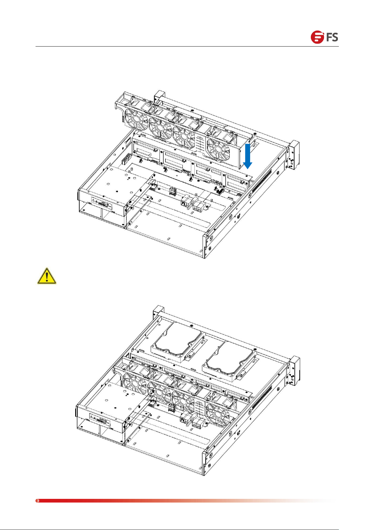
5.2 Fan Installation
The system adopts modular fan wall heat dissipation, and the wind wall support module has no
screws and no tools to install. The installation diagram is as follows:
Note: The gap in the fan wall is aligned with the snap on the chassis, and then the
power cables of each fan are connected to the backplane.
The installation is complete
Page 37
Data Center, Enterprise & ISP Network Solutions
37
①
②
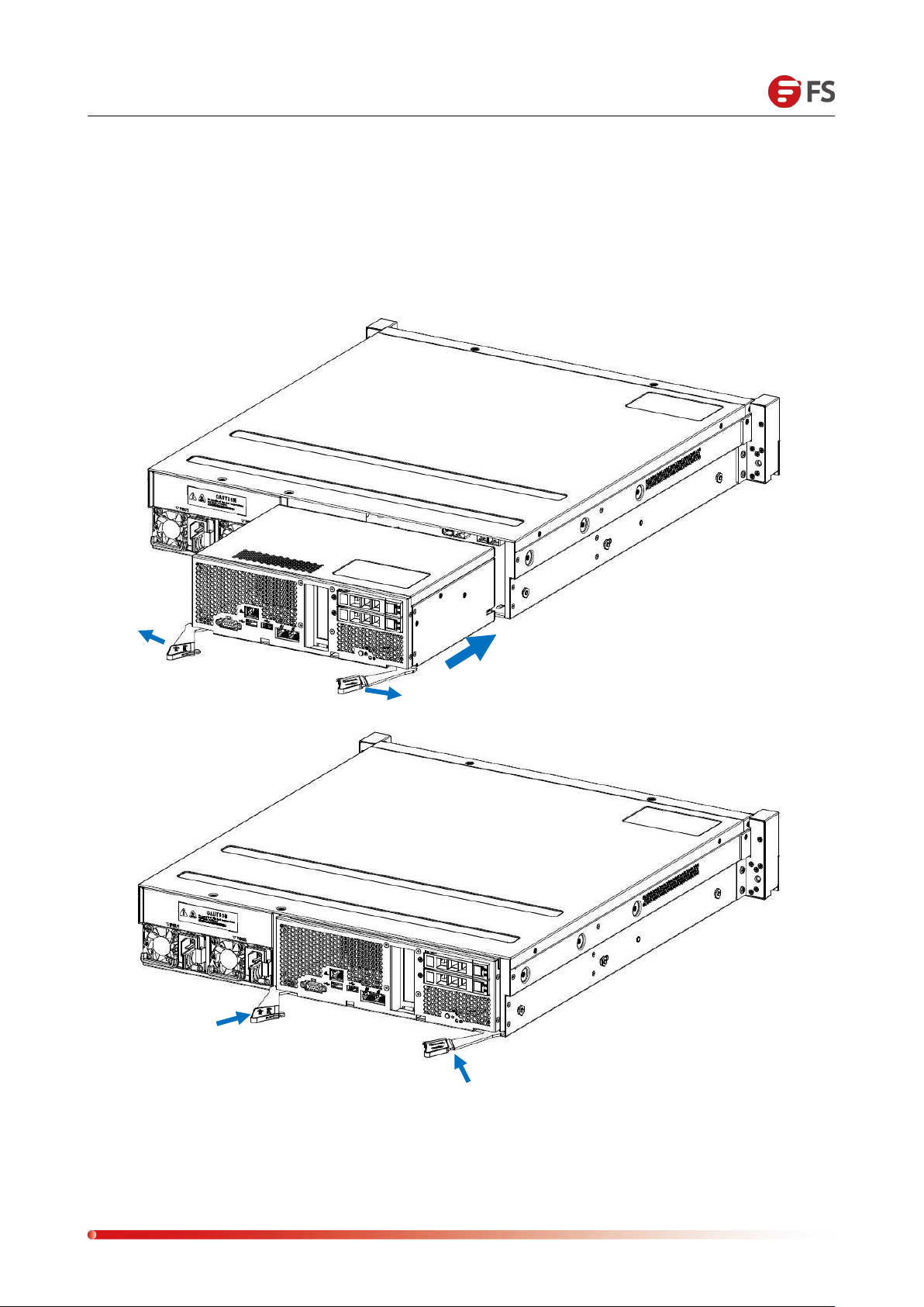
5.3 Controller Module Installation
The system adopts a modular installation and supports hot swap; installation and maintenance are
simple and convenient. The installation diagram is as follows:
Page 38
Data Center, Enterprise & ISP Network Solutions
38
③
①
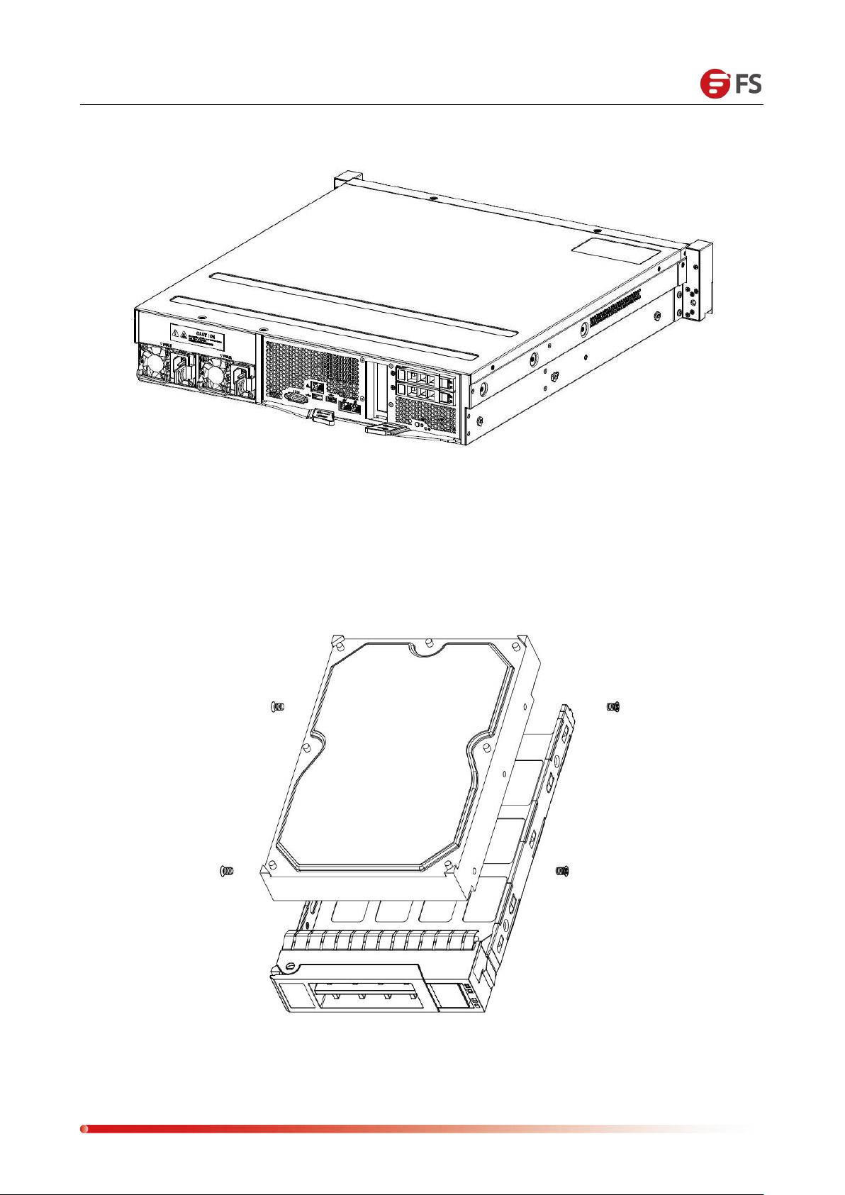
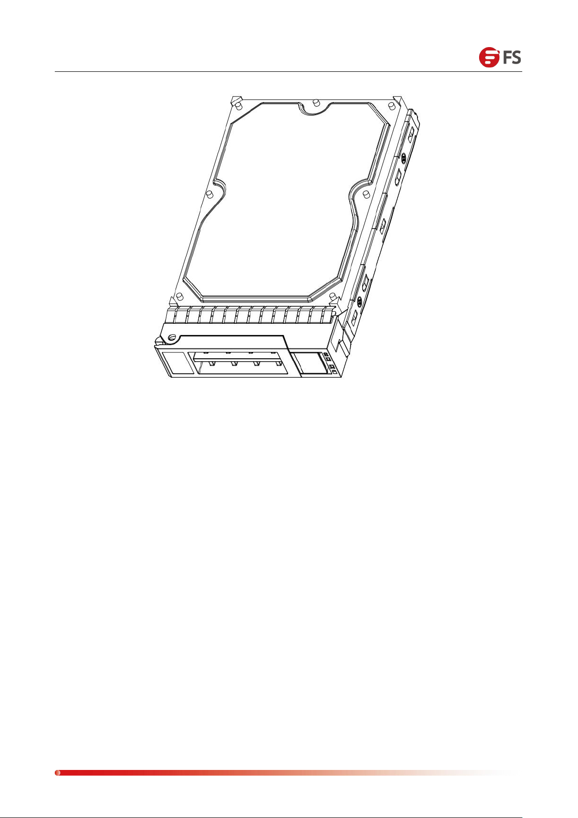
5.4 Hard Disk Installation
The system supports 16 3.5-inch hard disks. The installation method of each hard disk is the same.
The following installation diagrams are as follows:
Page 39
Data Center, Enterprise & ISP Network Solutions
39
②
The installation is complete
Page 40
Data Center, Enterprise & ISP Network Solutions
40
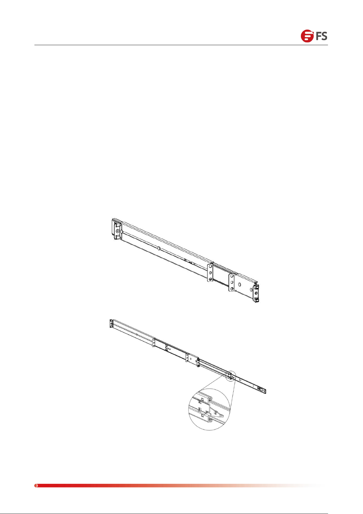
1. Pull out the inner rail of the rail. As shown below:
①
②
Chapter
6.1 Overview
This section describes the procedures for using RS-6388.
Select a suitable location on the rack to place the server system. This location should meet the
following conditions: clean, well-ventilated, dust-free or dust-free areas, take care to avoid high
temperatures, electrical noise and electromagnetic interference, and you also need to place a
power outlet nearby.
6.2 Rail Mounting
RS-6388 uses a full set of screw-free tool-free rails, easy to install. Please use the following steps to
install the system into a rack.
Ⅵ
System Cabinet Installation
Page 41

Data Center, Enterprise & ISP Network Solutions
41
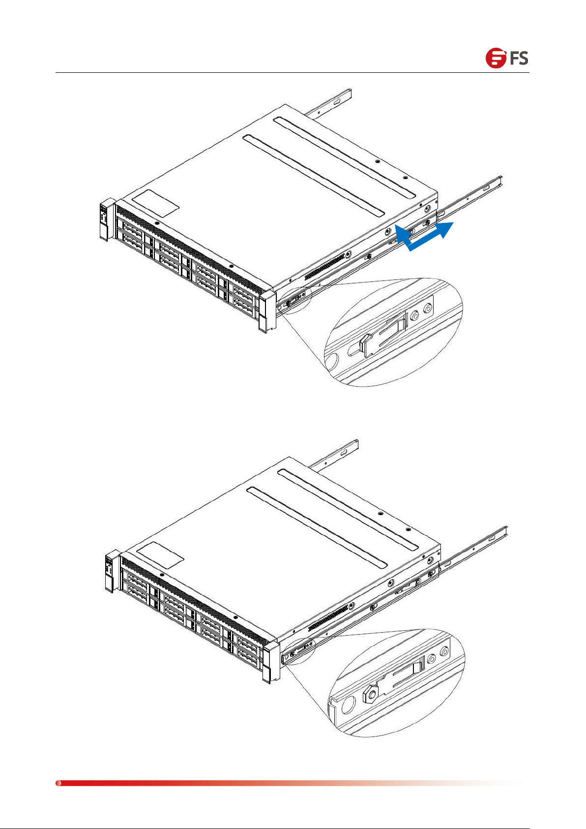
2. Install the extracted inner rail into the chassis, as shown below.
③
①
Page 42
Data Center, Enterprise & ISP Network Solutions
42
②
③
Page 43
Data Center, Enterprise & ISP Network Solutions
43
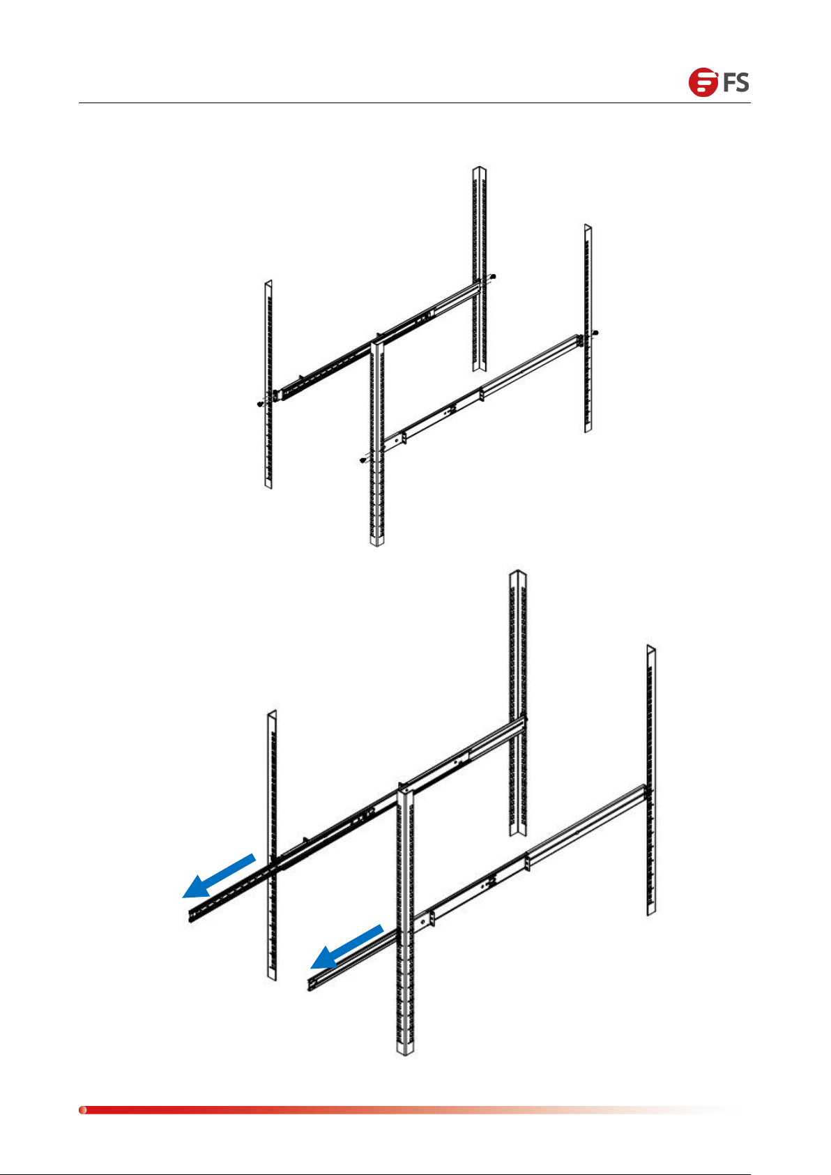
3. Secure the rails into the cabinet and pull out the middle rails. As shown below:
①
②
Page 44
Data Center, Enterprise & ISP Network Solutions
44
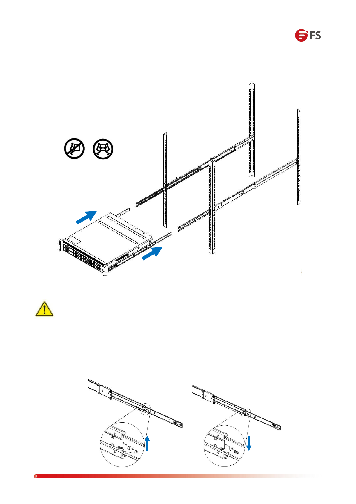
4. Place the system in a full rack and place it horizontally into the rails and into the rack. As
The left side of the buckle is lifted up
Press down on the right side
shown below:
Note: In the flat push-in process, there is a buckle on each side of the slide rails on
both sides. The left buckle is lifted upwards and the right buckle is pressed downwards to
continue pushing. As shown below:
Page 45
Data Center, Enterprise & ISP Network Solutions
45
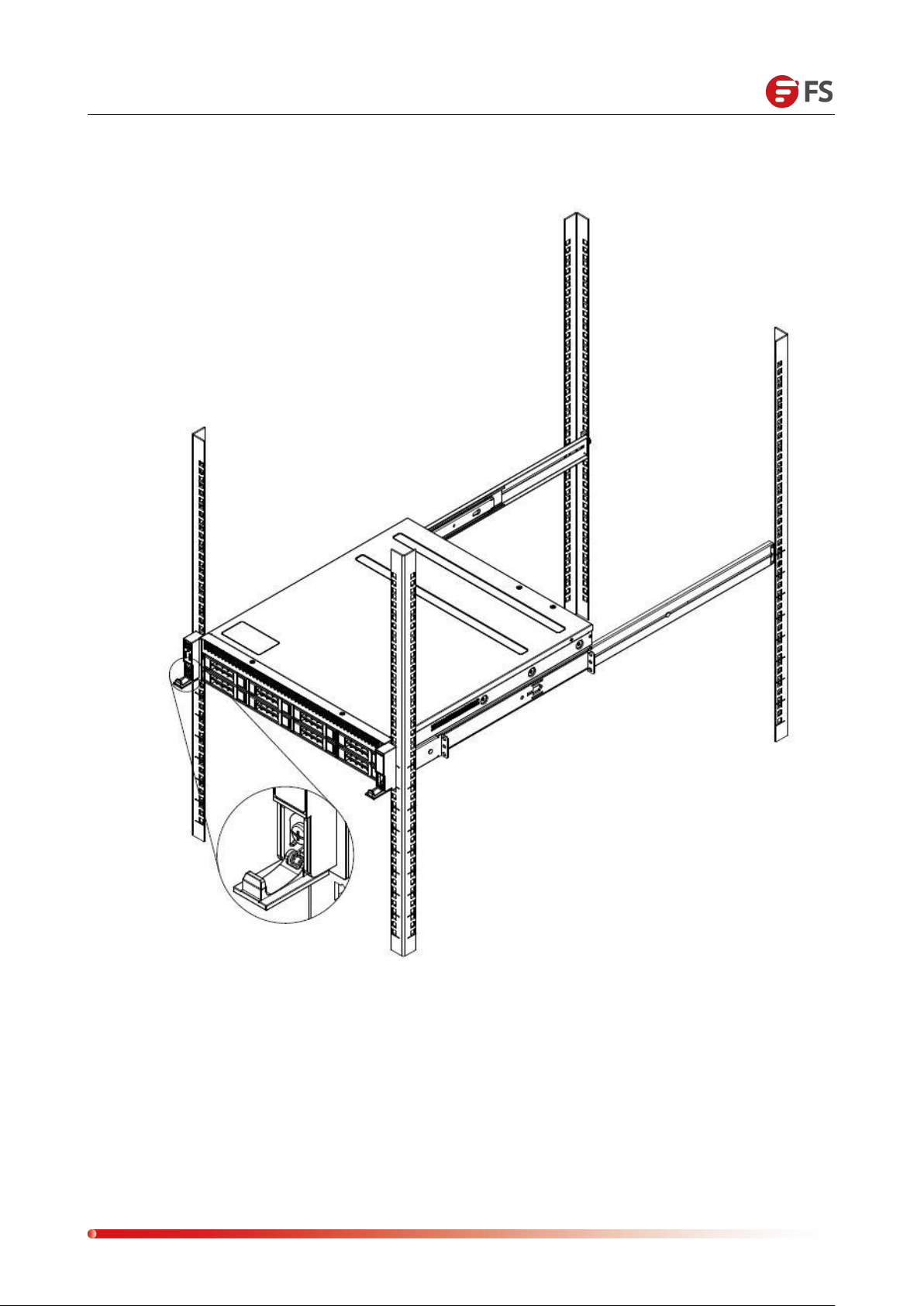
5. Lock the fixing screw, as shown below:
Page 46
Data Center, Enterprise & ISP Network Solutions
46
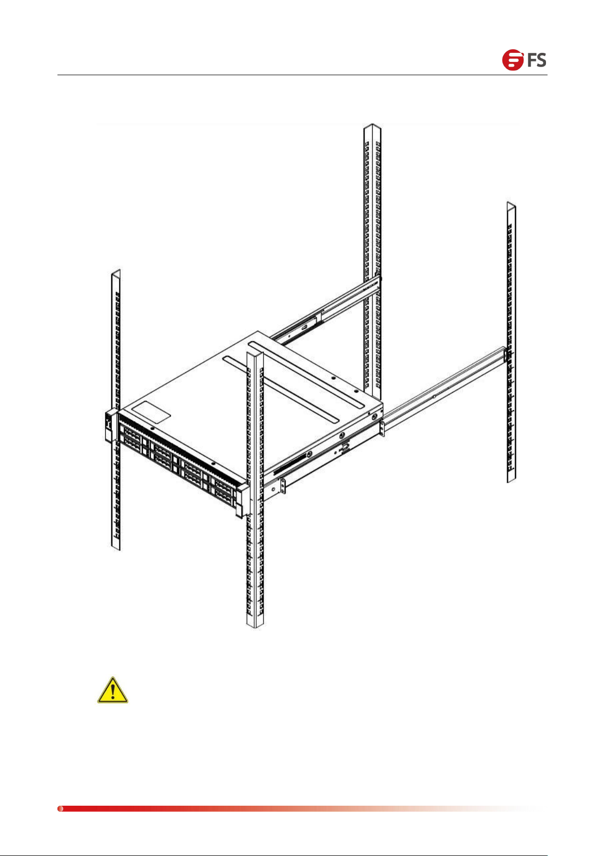
6. The final schematic of the entire storage server system in the rack is as follows:
Warning: Do not pull the handle of the server system. Otherwise, the system
will be pulled out of the rack, which may make the system power off or down. The
rack must be secure, the unstable rack will cause the rack to tip over.
Page 47
 Loading...