

FSC P20W-5, P22W-5 Service Manual
20"&22" LCD Color Monitor FSC P20W-5&P22W-5
-1-
Service
Service
Service
Horizontal Frequency
28kHz – 80kHz
TABLE OF CONTENTS
Description Page Description Page
SAFETY NOTICE
ANY PERSON ATTEMPTING TO SERVICE THIS CHASSIS MUST FAMILIARIZE HIMSELF WITH THE
CHASSIS AND BE AWARE OF THE NECESSARY SAFETY PRECAUTIONS TO BE USED WHEN SERVICING
ELECTRONIC EQUIPMENT CONTAINING HIGH VOLTAGES.
Table Of Contents.......…….................……...........…........1
Revision List.…........................………................……......2
Important Safety Notice.………….…..................……......3
1.Monitor Specification..............................………........4
2.LCD Monitor Description…………………………….......6
3.Operation Instruction…………...............……...........7
3.1.General Instructions...........................…...........7
3.2.Control Button…………….…..............……...............7
3.3 Adjusting the Picture...........................…............8
4.Input/Output Specification............……………............11
4.1.Input Signal Connector............………….................11
4.2.Factory Preset Display Modes.........................13
4.3.Power Supply Requirements.........................13
4.4.Panel Specification.....………………..................14
5.Block Diagram…….…...................…………................18
5.1.Software Flow Chart………………………….............18
5.2.Electrical Block Diagram…………..…..….......20
6.Schematic……………...............................….....22
6.1.Main Board.............................…................22
6.2.Power Board....……....................................30
7.PCB Layout..…………..........................................32
7.1.Main Board………........................................32
7.2.Power Board....……....................................33
7.3.Key Board……………………………………………34
8.Maintainability……….......................................35
8.1.Equipments and Tools Requirement...............35
8.2.Trouble Shooting…………..............................35
9. White-Balance, Luminance adjustment.............41
10.Exploded View.....….......….....................43
11.BOM List….....................................................45
12.Different Parts List….............................................80
CAUTION: USE A SEPARATE ISOLATION TRANSFOMER FOR THIS UNIT WHEN SERVICING
20"&22" LCD Color Monitor FSC P20W-5&P22W-5
-2-
Revision List
Revision Date Revision History TPV Model Name
TARAM3DBIWM7DC
A00 Jul.-27-2008 Initial Release
TARAM3DBIWM78C
TCRSM3DBIWM7DC
A01 Jul.-29-2008 Add new BOM for P22W-5
TCRSM3DBIWM75C
A02 Sep.-29-2008 Add new BOM for P22W-5 TCRGM3DBIWM8DC

20"&22" LCD Color Monitor FSC P20W-5&P22W-5
-3-
Important Safety Notice
Proper service and repair is important to the safe, reliable operation of all AOC Company Equipment. The service
procedures recommended by AOC and described in this service manual are effective methods of performing service
operations. Some of these service operations require the use of tools specially designed for the purpose. The
special tools should be used when and as recommended.
It is important to note that this manual contains various CAUTIONS and NOTICES which should be carefully read in
order to minimize the risk of personal injury to service personnel. The possibility exists that improper service
methods may damage the equipment. It is also important to understand that these CAUTIONS and NOTICES ARE
NOT EXHAUSTIVE. AOC could not possibly know, evaluate and advise the service trade of all conceivable ways in
which service might be done or of the possible hazardous consequences of each way. Consequently, AOC has not
undertaken any such broad evaluation. Accordingly, a servicer who uses a service procedure or tool which is not
recommended by AOC must first satisfy himself thoroughly that neither his safety nor the safe operation of the
equipment will be jeopardized by the service method selected.
Hereafter throughout this manual, AOC Company will be referred to as AOC.
WARNING
Use of substitute replacement parts, which do not have the same, specified safety characteristics may create shock,
fire, or other hazards.
Under no circumstances should the original design be modified or altered without written permission from AOC.
AOC assumes no liability, express or implied, arising out of any unauthorized modification of design.
Servicer assumes all liability.
FOR PRODUCTS CONTAINING LASER:
DANGER-Invisible laser radiation when open AVOID DIRECT EXPOSURE TO BEAM.
CAUTION-Use of controls or adjustments or performance of procedures other than those specified herein may
result in hazardous radiation exposure.
CAUTION -The use of optical instruments with this product will increase eye hazard.
TO ENSURE THE CONTINUED RELIABILITY OF THIS PRODUCT, USE ONLY ORIGINAL MANUFACTURER'S
REPLACEMENT PARTS, WHICH ARE LISTED WITH THEIR PART NUMBERS IN THE PARTS LIST SECTION OF
THIS SERVICE MANUAL.
Take care during handling the LCD module with backlight unit
-Must mount the module using mounting holes arranged in four corners.
-Do not press on the panel, edge of the frame strongly or electric shock as this will result in damage to the screen.
-Do not scratch or press on the panel with any sharp objects, such as pencil or pen as this may result in damage to
the panel.
-Protect the module from the ESD as it may damage the electronic circuit (C-MOS).
-Make certain that treatment person’s body is grounded through wristband.
-Do not leave the module in high temperature and in areas of high humidity for a long time.
-Avoid contact with water as it may a short circuit within the module.
-If the surface of panel becomes dirty, please wipe it off with a soft material. (Cleaning with a dirty or rough cloth may
damage the panel.)
20"&22" LCD Color Monitor FSC P20W-5&P22W-5
-4-
1. Monitor Specifications
P20W-5:
Item Specification
System 51cm (20") color LCD
Active Area 433.44 x 270.90mm
Pixel Pitch 0.258mm (H) /0.258 mm (V)
Resolution 1680 x 1050
Display Colors 16.7M (8-bit)
Contrast 1000:1(type)
Luminance 300cd/m²(type)
Panel
Response time (type) 5ms
Analog: 0. 7Vp-p(standard), 75 OHM, Positive
Video
DVI-D / HDMI with HDCP
H-Frequency 28kHz (15kHz interlaced modes) to 80kHz
Input
V-Frequency 50 Hz to 75 Hz
Monitor: 475.4mm x 359.5mm x 226.0 (incl. Stand)mm
Main Dimensions(W x H x D)
Packed Monitor: 561.0mm x 265.0mm x438.0mm
Weight Monitor: 7.0 kg(incl. Stand)
Normal operation 43W
ECO operating mode 33W
Power consumption
Energy saving mode 0W in the 0W operating mode
Operating temperature: +15°C - +35°C; Operating Humidity: 20% - 85%
Storage Temperature: +5°C - +35°C; Storage Humidity: 5% - 85%
Environmental Condition
Transport Temperature: -20°C - +60°C; Storage Humidity: 15% - 98%
Safety compliance: CE (EN60950), cUL, CSA, CCC
EMC compliance: CE, FCC, C-tick, MPRII and TCO03
Environmental compliance: RoHS, EPA, Blue Angel, RESY
Ergonomics compatibility: TCO03, ISO 13406 –2
VESA DPMS compliant
DDC 2B and DDC CI compliant. Incorporated with FSC Displayview command
interface SW.
Windows XP and Windows Vista compliant
Compliant
RESY compliant components
20"&22" LCD Color Monitor FSC P20W-5&P22W-5
-5-
P22W-5:
Item Specification
System 56cm (22") color LCD
Active Area 473.8 x 296.1mm
Pixel Pitch 0.282mm (H) /0.282 mm (V)
Resolution 1680 x 1050
Display Colors 16.7M (8-bit)
Contrast 1000:1(type)
Luminance 300cd/m²(type)
Panel
Response time (type) 5ms
Analog: 0. 7Vp-p(standard), 75 OHM, Positive
Video
DVI-D / HDMI with HDCP
H-Frequency 28kHz (15kHz interlaced modes) to 80kHz
Input
V-Frequency 50 Hz to 75 Hz
Monitor: 510mm x 371mm x 226.0 (incl. Stand)mm
Main Dimensions(W x H x D)
Packed Monitor: 616.0mm x 484.0mm x250.0mm
Weight Monitor: 7.4 kg(incl. Stand)
Normal operation 49W
ECO operating mode 37W
Power consumption
Energy saving mode 0W in the 0W operating mode
Operating temperature: +15°C - +35°C; Operating Humidity: 20% - 85%
Storage Temperature: +5°C - +35°C; Storage Humidity: 5% - 85%
Environmental Condition
Transport Temperature: -20°C - +60°C; Storage Humidity: 15% - 98%
Safety compliance: CE (EN60950), cUL, CSA, CCC
EMC compliance: CE, FCC, C-tick, MPRII and TCO03
Environmental compliance: RoHS, EPA, Blue Angel, RESY
Ergonomics compatibility: TCO03, ISO 13406 –2
VESA DPMS compliant
DDC 2B and DDC CI compliant. Incorporated with FSC Displayview command
interface SW.
Windows XP and Windows Vista compliant
Compliant
RESY compliant components
20"&22" LCD Color Monitor FSC P20W-5&P22W-5
-6-
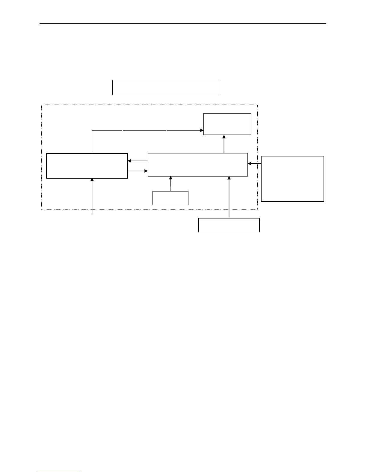
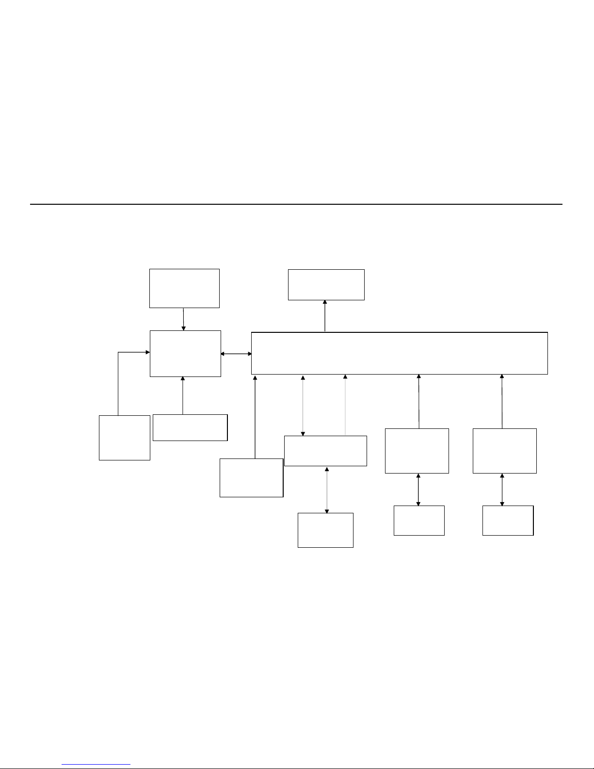
2. LCD Monitor Description
The LCD MONITOR will contain a main board, a power board, a sensor board and a key board which house the flat
panel control logic, brightness control logic and DDC.
The power board will provide the AC to DC voltage to drive backlight and the main board chips each voltage.
Video signal, DDC
Power board
Include:Inverter and Adapter
Flat Panel and
CCFL backlight
Main Board
Key board
RS232 Connector
For white balance
adjustment in factory
mode
HOST Computer
CCFL Drive.
AC-IN
100V-240V
Monitor Block Diagram
20"&22" LCD Color Monitor FSC P20W-5&P22W-5
-7-
3. Operating Instructions
3.1 General Instructions
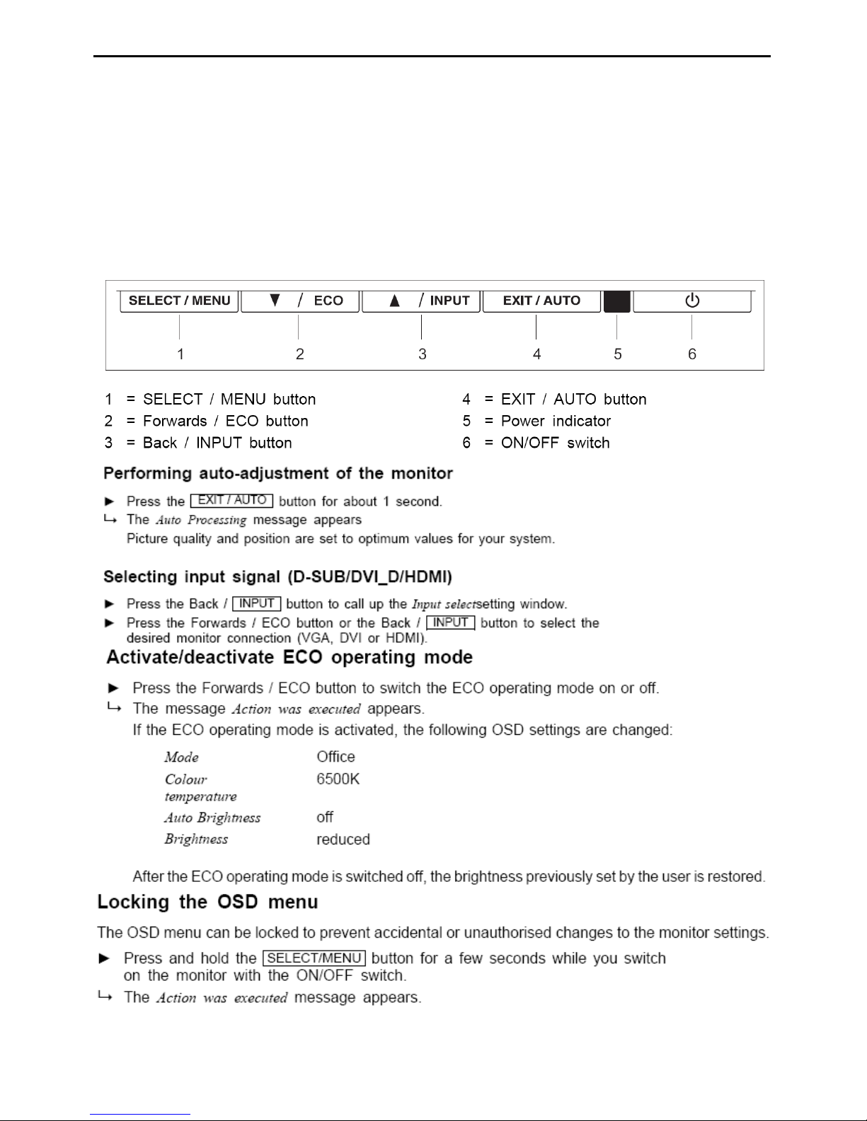
Press the power button to turn the monitor on or off. The other control buttons are located in the front of the monitor.
By changing these settings, the picture can be adjusted to your personal preferences.
-
The power cord should be connected.
-
Connect the video cable from the monitor to the video card.
-
Press the power button to turn on the monitor, the power indicator will light up.
3.2 Controls and Buttons
External Controls:
20"&22" LCD Color Monitor FSC P20W-5&P22W-5
-8-
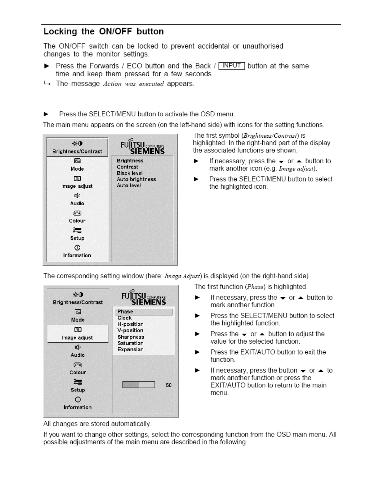
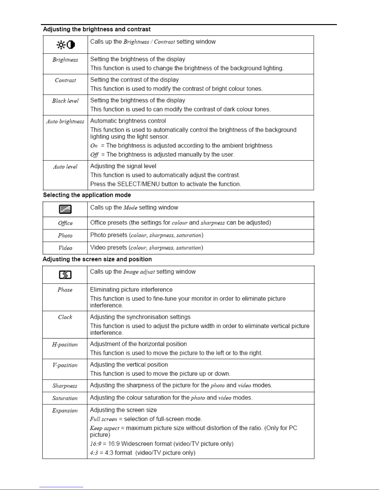
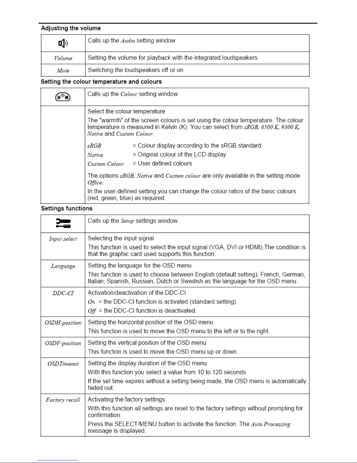
3.3 Adjusting the Picture
To set the OSD menu, perform the following steps:
20"&22" LCD Color Monitor FSC P20W-5&P22W-5
-9-
20"&22" LCD Color Monitor FSC P20W-5&P22W-5
-10-
20"&22" LCD Color Monitor FSC P20W-5&P22W-5
-11-
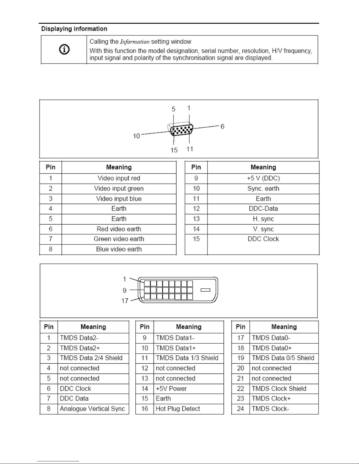
4. Input/Output Specification
4.1 Input Signal Connector
D-Sub Input
DVI Input
20"&22" LCD Color Monitor FSC P20W-5&P22W-5
-12-
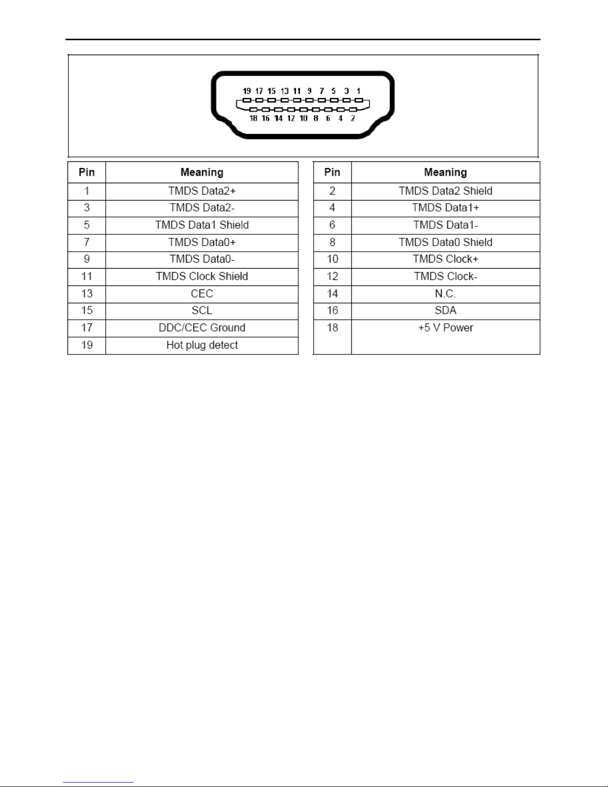
HDMI monitor connections
20"&22" LCD Color Monitor FSC P20W-5&P22W-5
-13-
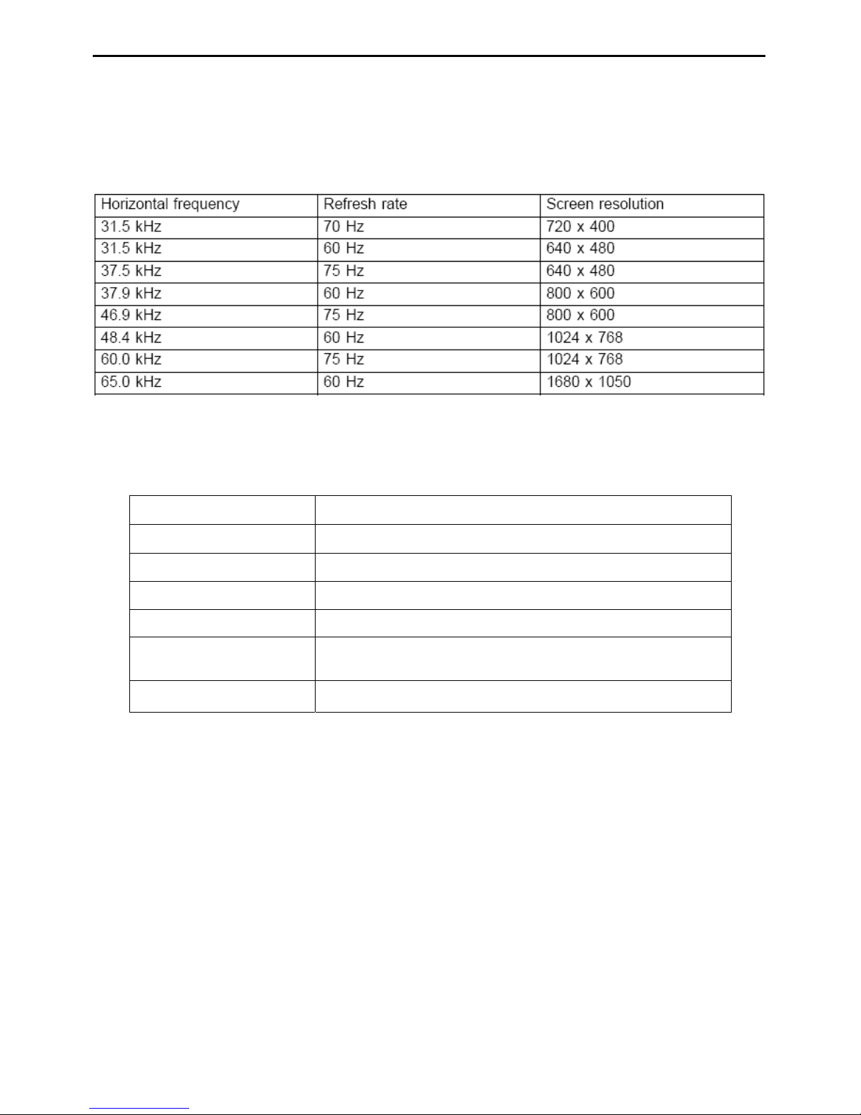
4.2 Factory Preset Display Modes
The picture position and size have been set to optimum values at the factory for the operating modes listed above.
Depending on the screen controller used, it may be necessary to adjust the display position and size. In this case,
you can change and save the settings
The following are the most frequently used of the preset operating modes:
4.3 Power Supply Requirements
A/C Line voltage range
90 VAC - 264 VAC ± 10 %
A/C Line frequency range
50 ± 3Hz, 60 ± 3Hz
Current
1.5 A max. at 100V; 0.5 A max. at 240V
Peak surge current < 60 A peak at 240 V AC and cold starting
Leakage current < 2.5 mA for power from Wall-outlet
Power line surge
No advance effects (no loss of information or defect)
with a maximum of 1 half-wave missing per second
Power factor correction:
According to EN 61000-3-2 or power consumption is
< 75W
20"&22" LCD Color Monitor FSC P20W-5&P22W-5
-14-
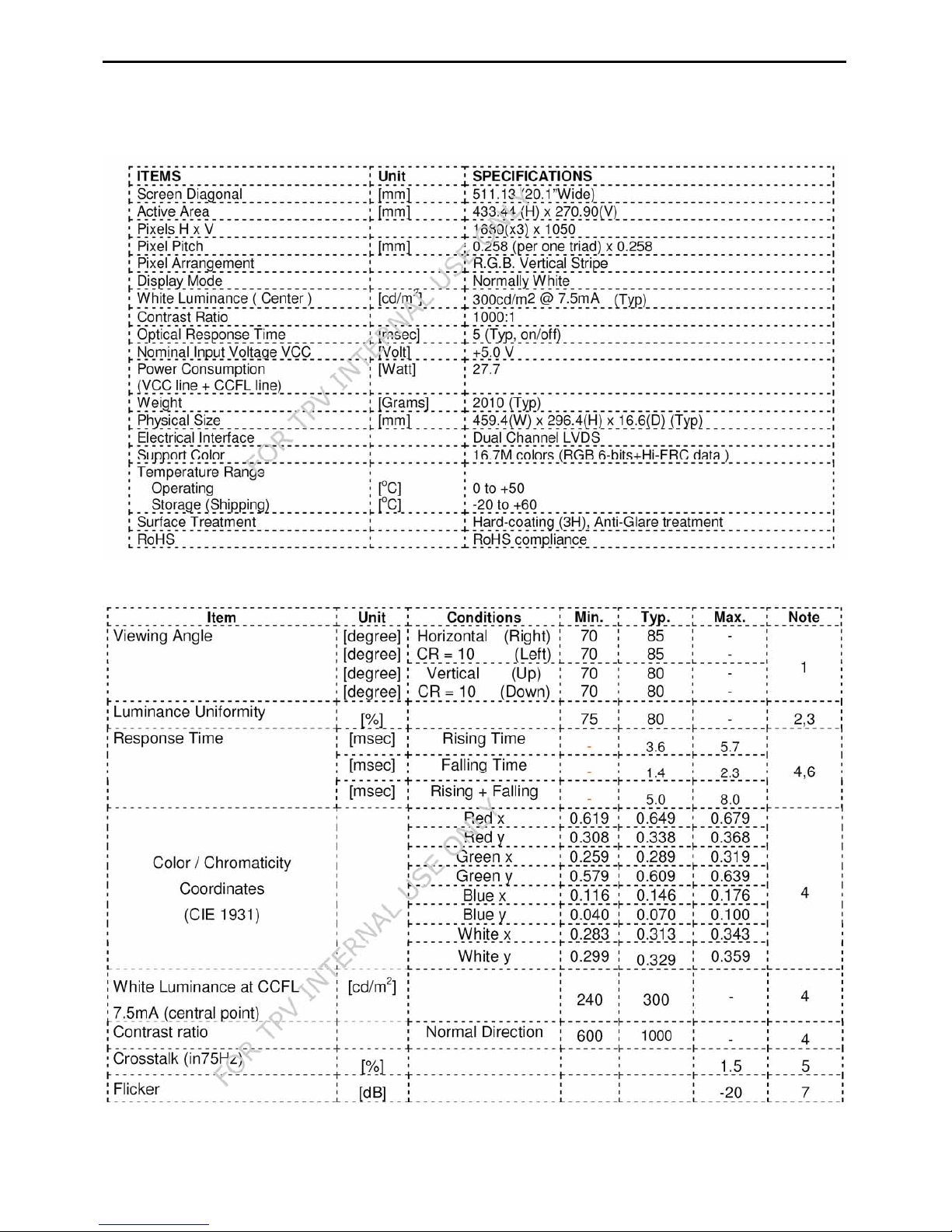
4.4 Panel Specification
M201EW02:
Display Characteristics
Optical Characteristics
20"&22" LCD Color Monitor FSC P20W-5&P22W-5
-15-
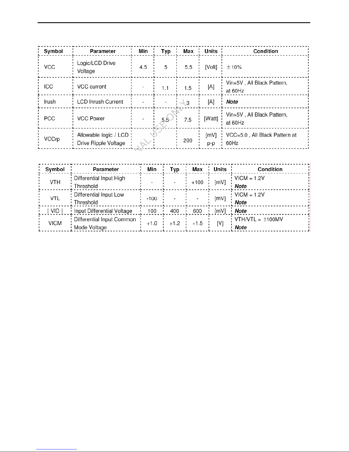
Electrical characteristics
Power Specification
Signal Electrical Characteristics
20"&22" LCD Color Monitor FSC P20W-5&P22W-5
-16-
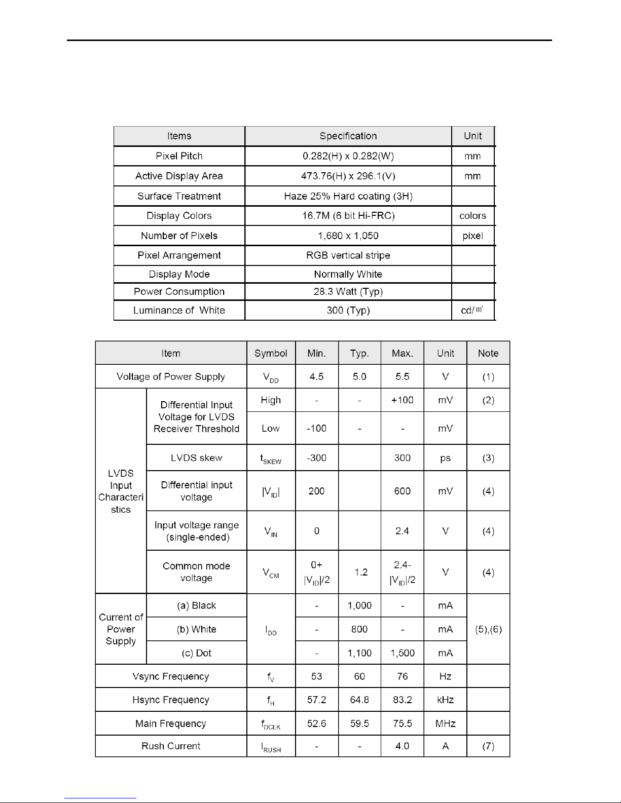
LTM220M2-L01
LTM220M2-L01 is a color active matrix liquid crystal display (LCD) that uses amorphous silicon TFT (Thin Film
Transistor) as switching components. This model is composed of a TFT LCD panel, a driver circuit and a back light
unit. The resolution of a 20.1” is 1680 x 1050 and this model can display up to 16.7 millions colors.
General Information
Mechanical Information
20"&22" LCD Color Monitor FSC P20W-5&P22W-5
-17-
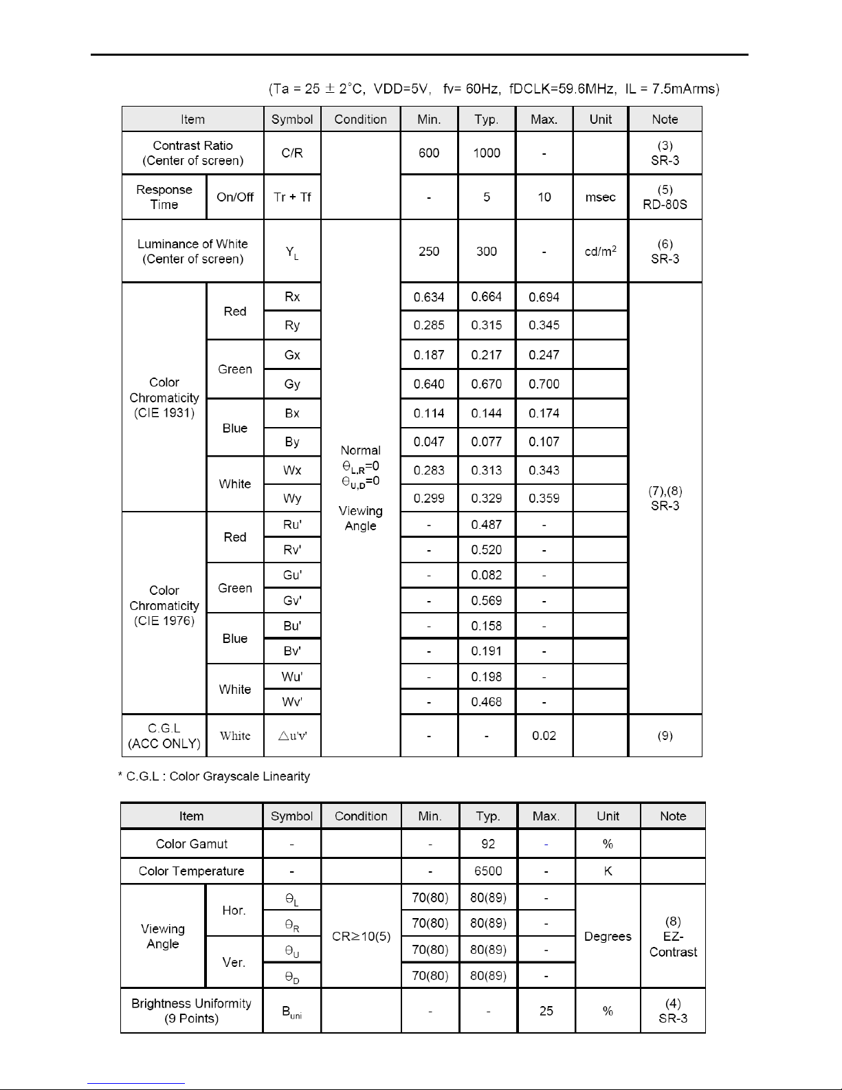
Optical Characteristics
20"&22" LCD Color Monitor FSC P20W-5&P22W-5
-18-
5. Block Diagram
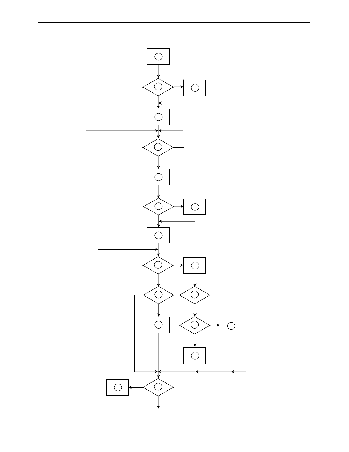
5.1 Software Flow Chart
1
2
N
Y
5
Y
N
10
Y
N
12
Y
N
7
Y
N
6
4
3
8
9
14
11
13
Y
N
15
Y
N
16
17
19
Y
N
18

20"&22" LCD Color Monitor FSC P20W-5&P22W-5
-19-
1) MCU initialize.
2) Is the EEPROM blank?
3) Program the EEPROM by default values.
4) Get the PWM value of brightness from EEPROM.
5) Is the power key pressed?
6) Clear all global flags.
7) Are the AUTO and SELECT keys pressed?
8) Enter factory mode.
9) Save the power key status into EEPROM.
Turn on the LED and set it to green color.
Scalar initialize.
10) In standby mode?
11) Update the lifetime of back light.
12) Check the analog port, are they’re any signals coming?
13) Does the scalar send out an interrupt request?
14) Wake up the scalar.
15) Are there any signals coming from analog port?
16) Display "No connection Check Signal Cable" message. And go into standby mode after the message
disappears.
17) Program the scalar to be able to show the coming mode.
18) Process the OSD display.
19) Read the keyboard. Is the power key pressed?
20"&22" LCD Color Monitor FSC P20W-5&P22W-5
-20-
5.2 Electrical Block Diagram
5.2.1 Scalar Board Block Diagram
MCU
MTV416GMV
(U402)
Scalar MST6251DA-LF-165
(Include ADC, OSD)
(U401)
EEPROM
M24C32
(U405)
D-Sub
Connector
(CN102)
EEPROM
M24C02
(
U102
)
H sync
V sync
RGB
VGA_SDA,
VGA_SCL
MSDA
MSCL
LCD Interface
(CN401)
Key Board Control
CN403
Crystal
24MHz
(X402)
Crystal
14.318MHz
(X401)
EEPROM
M24C02
(U101)
DVI_SCL
DVI_SDA
DVI Connector
(CN101)
Digital
Video
Data
CLOCK
HDMI
Connector
(CN501)
EEPROM
M24C02
(
U503
)
HDMI_SDA,
HDMI_SCL
20"&22" LCD Color Monitor FSC P20W-5&P22W-5
- 21 -
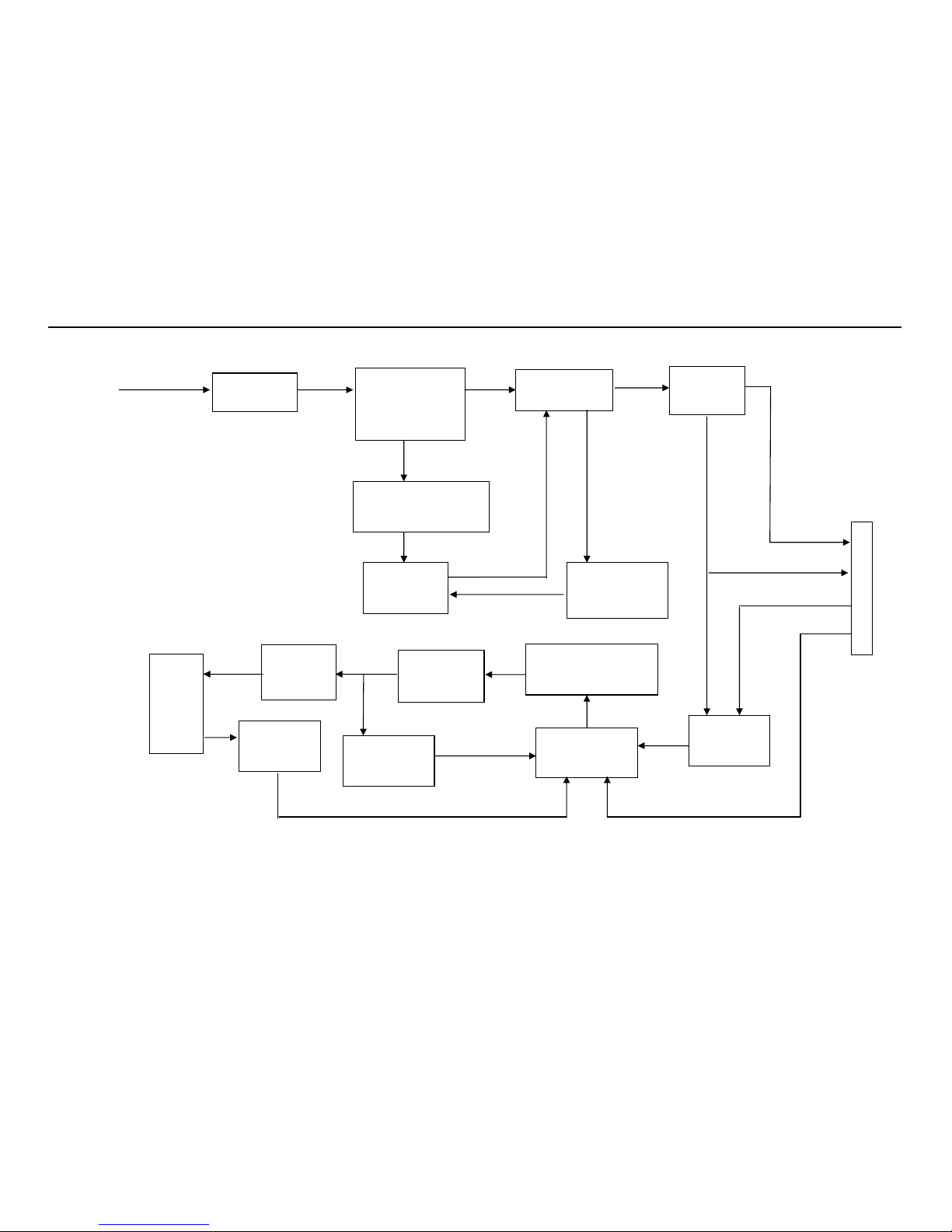
5.2.2 Power Board Block Diagram
EMI filter
Bridge Rectifier
and Filter
Start Circuit
R903, R904, R905
PWM
Control IC
Transformer
Over Voltage
Protect
Rectifier
Diodes
AC input
5V
12V
ON/OFF
Control
PWM
Control IC
Feedback
Circuit
Output
Circuit
DC Convert
Circuit
MOSFET Q802, Q803,
Over Voltage
Lamp
ON/OFF
DIM
CN902
20"&22" LCD Color Monitor FSC P20W-5&P22W-5
- 22 -
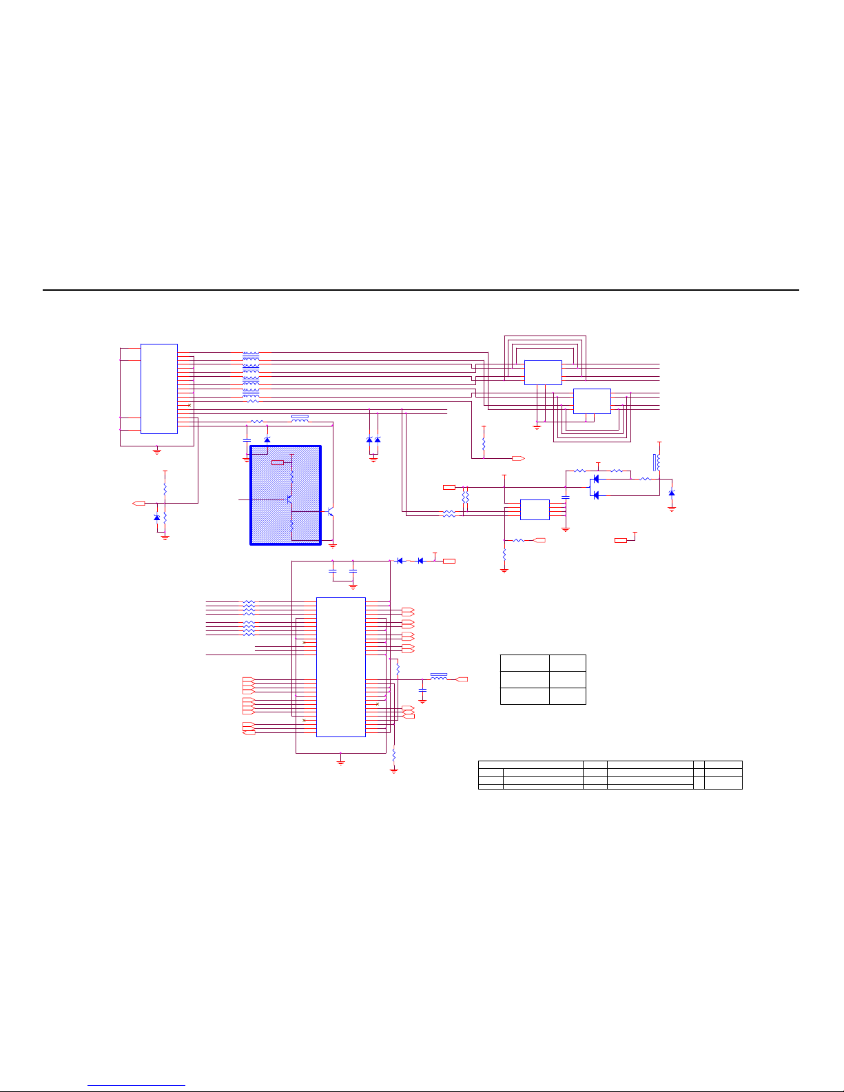
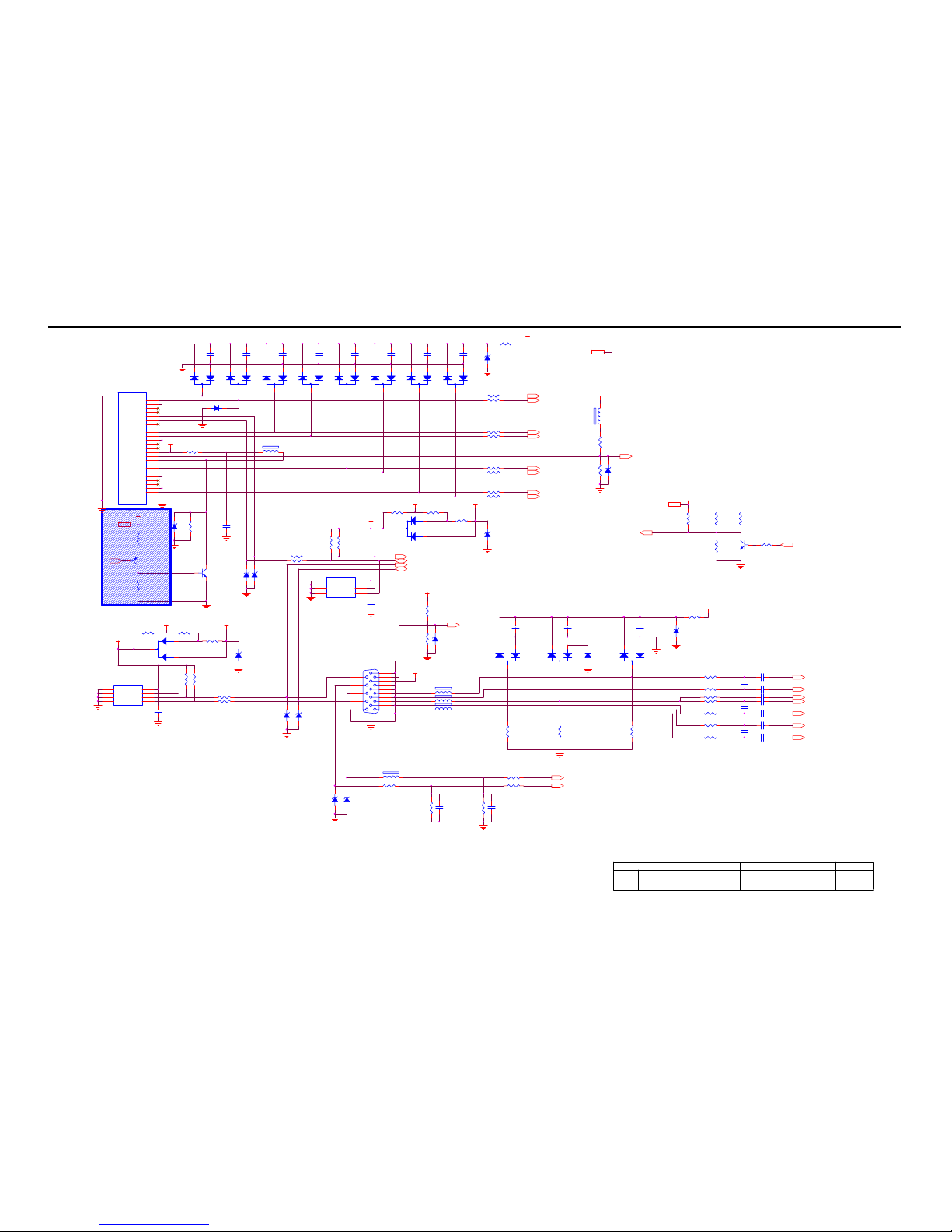
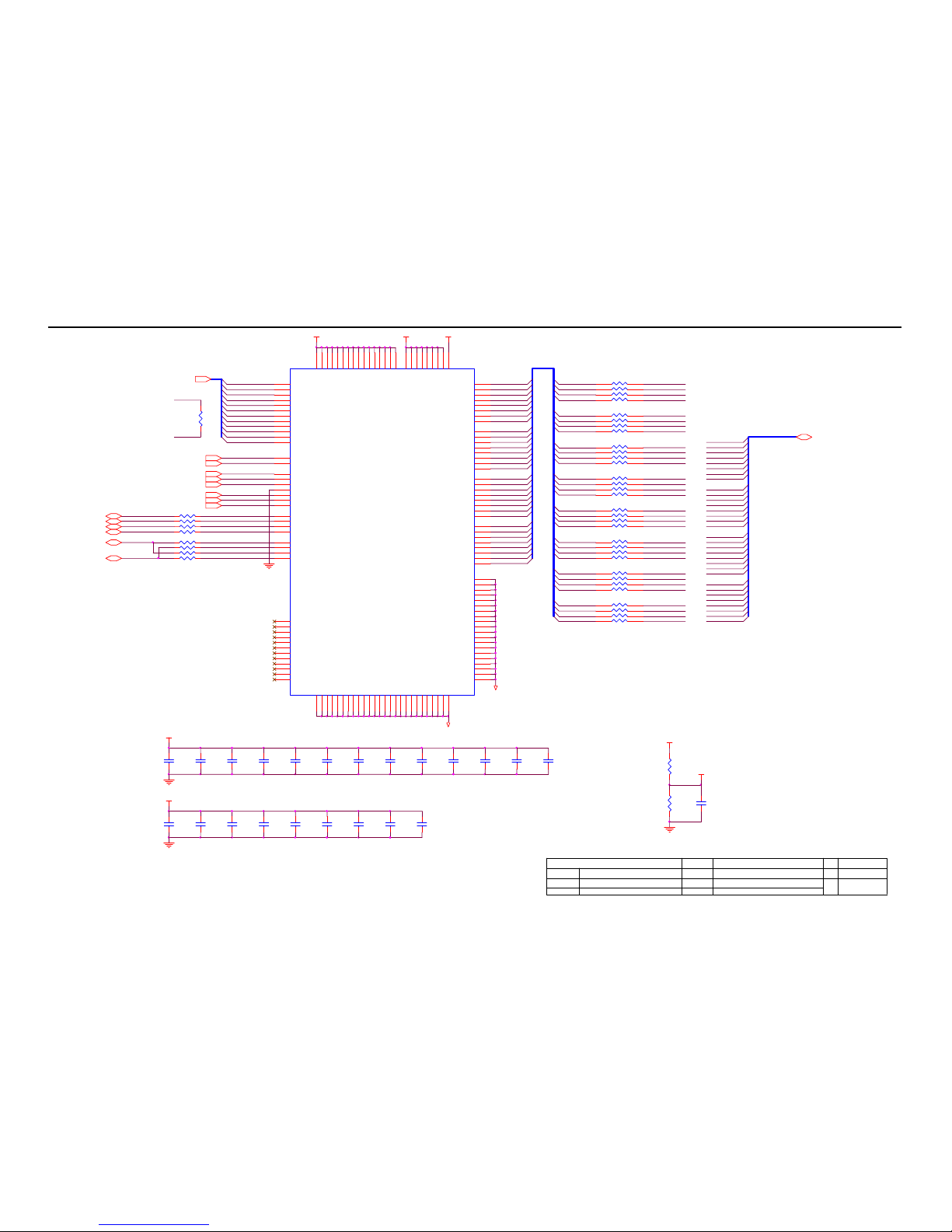
6. Schematic
6.1 Main Board
D1+_HDMI
HDMI1_SDA
HDMI
RXCC+ 5
C
A3
110Wednesday , June 11, 2008
715G2651-C-2
<
称爹
>
01.HDMI Input
G2651-C-2-X-2-080611
OEM MOD EL Size
Rev
Date
Sheet
of
TPV MOD EL
PCB NAME
称爹
T P V ( Top Victory El ectronics Co . , Ltd. )
Key Component
絬 隔 瓜 絪 腹
CN501
HDMI
20
21
1
2
3
4
5
6
7
8
9
10
11
12
13
14
15
16
17
18
19
23
22
SHELL1
SHELL2
D2+
D2 Shield
D2D1+
D1 Shield
D1D0+
D0 Shield
D0CK+
CK Shield
CK-
CE Remote
NC
DDC CLK
DDC DATA
GND
+5V
HP DET
SHELL4
SHELL3
HDMI1_CK+
HDMI1_CK-
R526 0R05 1/10W 5%
VMCU
FB506
600 OHM
VCCHDMI
CK-_HDMI
C504
0.1uF 50V
RXC+3
HDMII_HOTPLUG 6
DVI_SCL
HDMI1_D2+
R508
10K 1/10W 5%
RX1-3
V_5V
HDMI1_SDA
DVI_SDA4
U505
RClamp0524P.TCT
1
2
3
4
5 6
7
8
9
10
IN1
IN2
GND
IN3
IN4 OUT4
OUT3
GND
OUT2
OUT1
FB507
300 OHM
R524 0R05 1/10W 5%
R515
NC
VCCHDMI2
HDMI1_D2+
CK+_HDMI
HDMII_SDA 5,6
HDMI1_HOTPLUG
HDMI1_D2-
C501
0.1uF 50V
EDID_W P 3
HDCP_HP3
V_5V
R516
10K 1/10W 5%
DVI_SCL4
LOW
R501 1K 1/10W 5%
VCCHDMI
FB504
90 ohm
124
3
R519 0R05 1/10W 5%
RX11+ 5
R507 100R 1/10W 5%
RX2+3
RX00+ 5
HDMI1_+5V
+5V 5
FB501
90 ohm
124
3
VMCU5
HDMI1_D0+
C517
0.1uF 50V
HDMI1_CK+
HDMI1_HOTPLUG
R529
NC
R525 0R05 1/10W 5%
RX00- 5
R527
10K 1/10W 5%
HDMI1_D1+
R528
0R05 1/10W 5%
HDCP_HP
R522 0R05 1/10W 5%
FB502
90 ohm
124
3
RX22+ 5
V_5V6
R513 NC
R518
10K 1/10W 5%
HDMI1_SCL
U504
RClamp0524P.TCT
1
2
3
4
5 6
7
8
9
10
IN1
IN2
GND
IN3
IN4 OUT4
OUT3
GND
OUT2
OUT1
RX22- 5
R504
10K 1/10W 5%
RXC-3
R530
0R05 1/10W 5%
R521 0R05 1/10W 5%
SW_HDMI
Q502
2N3906S-RTK/PS
HDMI1_SCL
ZD501
UDZSNP5.6B
R520 0R05 1/10W 5%
OUTPUT
D1-_HDMI
D0+_HDMI
VCCHDMI
D2+_HDMI
RX2-3
RX0-3
HDMI1_D0-
R505
10K 1/10W 5%
CEC
HDMI_CAB6
HDMI1_D0+
R517
100K 1/10W 5%
HDMI1_D1+
HDMI1_D2-
D507
LL4148
RX1+3
DVI
R506 100R 1/10W 5%
U501
FSHDMI08MTDX
1
2
3
4
5
6
7
8
9
10
11
12
13
14
15
16
17
18
19
20
21
22
23
24
25
26
27
28 29
30
31
32
33
34
35
36
37
38
39
40
41
42
43
44
45
46
47
48
49
50
51
52
53
54
55
56
1D2+
1D21D1+
1D1GND
1D0+
1D01CLK+
1CLKGND
2D2+
2D22D1+
2D1GND
2D0+
2D02CLK+
2CLKVcc3
CEC1
SCL1
SDA1
HPD1
CEC2
SCL2
SDA2
HPD2 VDDC
DGND
/OE_DDC
S_DDC
HPD
SDA
SCL
CEC
DGND
GND
Vcc3
Vcc3
/OE_TMDS
S_TMDS
GND
CLK-
CLK+
GND
D0-
D0+
GND
D1-
D1+
GND
D2-
D2+
Vcc3
Vcc3
ZD505
NC / UD ZS5.6B
1 2
U503
M24C02-WMN6TP
1
2
3
45
6
7
8
A0
A1
A2
GNDSDA
SCL
WP
VCC
C503
10uF/16V
RX0+3
HI
HDMI1_D1-
D506
LL4148
RXCC- 5
HDMI1_D0-
FB505 120 OHM
12
ZD504
UDZSNP5. 6B
1 2
ZD502
UDZSNP5.6B
R503
10K 1/10W 5%
D0-_HDMI
FB503
90 ohm
124
3
R523 0R05 1/10W 5%
R507~R514 close to U501
CEC 3
VCCHDMI
HDMI_HOTPLUG
HDMII_SCL 5,6
ZD503
UDZSNP5. 6B
C510
0.1uF 50V
SW_HDMI 5
DVI_SDA
D508
BAT54C
HDMI1_D1-
RX11- 5
HDMI1_CK-
+5V
HDMI1_+5V
2008/6/7 : For Green Mode
D2-_HDMI
R512
NC
Q501
2N3904S-RTK/PS
R514 0R05 1/10W 5%
20"&22" LCD Color Monitor FSC P20W-5&P22W-5
- 23 -
R143 1K 1/10W 5%
R175
0R05 1/10W 5%
RX0+ 2
D106
BAV99
3
1
2
D114
BAV99
3
1
2
R109 10R 1/10W 5%
RED- 5
VCCDVI
VGASDA
C117
0.047uF
ZD103
UDZSNP5.6B
1 2
DVI_CAB 6
R108
1K 1/10W 5%
R101
NC
R110
100K 1/10W 5%
C119 0. 047uF
RX0- 2
V_5V
RX1-IN
R103 10R 1/10W 5%
C116 0. 047uF
U102
M24C02-WMN6TP
1
2
3
4 5
6
7
8
A0
A1
A2
GND SDA
SCL
WP
VCC
C112
0.1uF
VCCHDMI2
A-HS
R137 100R 1/10W 5%
R111 10R 1/10W 5%
VCCHDMI
DVI_SCL 2
2008/6/7 : For Green Mode
D113
BAV99
3
1
2
RXC+ 2
C114
0.047uF
R145 1K 1/10W 5%
RX2+ 2
VMCU5
R133 100R 1/10W 5%
R132 470R 1/10W 5%
RED+ 5
VGA_SDA 6
V_5V
FB101 32 OHM1 2
R139
75R 1/10W 5%
C103
0.1uF
C144
NC
RX1+IN
C121
47pF
RX0+IN
R104 10R 1/10W 5%
DVI_5V
ZD115
UDZSNP5.6B
1 2
A-RED
C106
0.1uF
D108
BAV99
3
1
2
GREEN- 5
R129 56R 1/10W 5%
R130 100R 1/10W 5%
R138
75R 1/10W 5%
D103
BAV99
3
1
2
R134 56R 1/10W 5%
RX0-IN
C143
NC
R147
2K2 1/10W 5%
AHS 5
V_5V6
R171
NC
VGASCL
ZD114
UDZSNP5.6B
1 2
VCCVGA
RX2+IN
R140
75R 1/10W 5%
DDC_WP 6
R172
0R05 1/10W 5%
HDCP_HP2
VGA_5V
R135 100R 1/10W 5%
R128
10K 1/10W 5%
CN101
JACK
1
2
3
4
5
6
7
8
9
10
11
12
13
14
15
17
18
19
20
21
23
24
16
22
26
25
T2-
T2+
SGND
T4-
T4+
DDCCLK
DDCDAT
A_VSYNC
T1-
T1+
SGND
T3T3+
+5V
GND
T0T0+
SGND
T5T5+
TC+
TC-
HPD
SGND
A_GND
A_GND
ZD106
UDZSNP5.6B
1 2
R127
10K 1/10W 5%
Q101
2N3904S-RTK/PS
RX1- 2
A-GREEN
R124
10K 1/10W 5%
C118
0.1uF
DVISCL
DVISCL
D112
BAV99
3
1
2
AVS 5
R169
10K 1/10W 5%
C113
0.047uF
R122 100R 1/10W 5%
BLUE+ 5
D102
BAV99
3
1
2
R136 56R 1/10W 5%
D119
LL4148
DVI_5V
RX2-IN
D105
BAV99
3
1
2
R125
100K 1/10W 5%
BLUE- 5
EDID_WP
ZD116
NC / UDZS5.6B
1 2
R102
1K 1/10W 5%
DVISDA
ZD101
UDZSNP5.6B
1 2
R126
1K 1/10W 5%
R173
0R05 1/10W 5%
C
C
210Wednesday , June 11, 2008
715G2651-C-2
<
称爹
>
02.VGA And DVI
G2651-C-2-X-2-080611
OEM MODEL Size
Rev
Date
Sheet
of
TPV MODEL
PCB NAME
称爹
T P V ( Top Victory Electronics Co . , Ltd. )
Key Component
絬 隔 瓜 絪 腹
VCCVGA
D109
LL4148
R117
10K 1/10W 5%
R115
4K7 1/10W 5%
ZD105
UDZSNP5.6B
1 2
RX1+ 2
C121,122 modfiy to 47pf
ZD109
UDZSNP5.6B
1 2
C110
0.1uF
RXC+IN
RXC- 2
VMCU
R116
4K7 1/10W 5%
D111
BAT54C
3
1
2
R131 100R 1/10W 5%
C147
0.1uF
FB104 300 OHM
1 2
VGA_SCL 6
ZD117
NC / UDZS5.6B
1 2
C104
0.1uF
R114
4K7 1/10W 5%
R146
2K2 1/10W 5%
R120
10K 1/10W 5%
EDID_WP2
VGA_5V
C109
0.1uF
VGA_CAB 6
RX2- 2
VCCDVI
FB108 120 OHM
12
GREEN+ 5
DVI_SDA 2
VCCVGA
VCCVGA
R170
0R05 1/10W 5%
Q102
2N3904S-RTK/PS
R112 10R 1/10W 5%
C102
0.1uF
ZD110
UDZSNP5.6B
1 2
SOG 5
C111
0.1uF
C122
47pF
D104
BAV99
3
1
2
R121 100R 1/10W 5%
C145
NC
C108
0.1uF
VCCDVI
R106 10R 1/10W 5%
ZD102
UDZSNP5.6B
1 2
FB103 32 OHM1 2
C107
0.1uF
C105
0.1uF
RXC-IN R113 10R 1/10W 5%
C101
0.1uF
D107
BAV99
3
1
2
ZD107
UDZSNP5.6B
1 2
U101
M24C02-WMN6TP
1
2
3
4 5
6
7
8
A0
A1
A2
GND SDA
SCL
WP
VCC
A-VS
DVISDA
R174
NC
R118
10K 1/10W 5%
D110
BAT54C
3
1
2
EDID_WP
ZD111
UDZSNP5.6B
1 2
Q103
2N3906S-RTK/PS
R119
NC
C115 0. 001uF
EDID_WP
R105 10R 1/10W 5%
VCCDVI
R144 100R 1/10W 5%
FB109
300 OHM
R123
10K 1/10W 5%
C120
0.047uF
V_5V
CN102
DB15
1
6
2
7
3
8
4
9
5
11
12
13
14
15
10
17 16
FB102 32 OHM1 2
A-BLUE
D101
BAV99
3
1
2
R107
10K 1/10W 5%
20"&22" LCD Color Monitor FSC P20W-5&P22W-5
- 24 -
FSDATAU5
FSCLK+
C413
0.1uF
FSDATAU 17FSDATA27
FSDATAU20
FSDQM01
FSDATA25
FSDQM00
FSDATAU 3
FSDATAU 20
FSDATA4
FSDATA18
FSDATA6
FSDQM10
FSDATAU1
R415 33R 1/10W 5%
FSDATAU18
RP407 100R 1/16W 5%
1
2
3
4
8
7
6
5
R419
10K 1/10W 5%
C428
0.1uF
/FSCAS5
FSDATA26
C422
0.1uF
FSDATAU 25
FSDATAU 28
C425
10uF/16V
C431
0.1uF
FSDQSU05
FSDATAU 8
FSDATAU 2
FSDATA22
FSDATA27
FSDATA28
FSDATA2
FSDATAU 16
FSDATA8
DGND
FSBKSEL05
FSDATA1
FSDATA20
C
A3
310Wednesday , June 11, 2008
715G2651-C-2
<
称爹
>
03.Frame Memory
G2651-C-2-X-2-080611
OEM MOD EL Size
Rev
Date
Sheet
of
TPV MOD EL
PCB NAME
称爹
T P V ( Top Victory Electronics Co . , Ltd. )
Key Component
絬 隔 瓜 絪 腹
+2.5V_D MQ
C414
0.1uF
C430
0.1uF
FSADDR1
FSDATAU4
FSDQS2
FSCLK+5
FSDATA3
FSDATA29
FSDATAU29
FSDQSU35
FSDATAU26
FSDATA17
/FSRAS
FSVREF
+2.5V_D MQ
FSDATA19
FSDATA18
FSDQM0
FSCLK-
FSADDR0
FSDATAU 21
FSDATAU15
FSDATAU28
FSDATA12
FSDATA9
FSDATA29
FSVREF
FSDATAU 13
FSADDR3
FSDATA13
RP404 100R 1/16W 5%
1
2
3
4
8
7
6
5
FSDATA16
RP406 100R 1/16W 5%
1
2
3
4
8
7
6
5
C417
0.1uF
FSDATAU 9
FSDATA4
FSDATA9
FSDATAU 24
FSDATAU27
FSCKE5
FSDATA31
C433
0.1uF
C412
0.1uF
FSCLK-
FSDATAU30
FSDATA22
FSDATA15
R420
10K 1/10W 5%
FSDATAU31
FSDQS1
RP402 100R 1/16W 5%
1
2
3
4
8
7
6
5
C426
0.1uF
FSDATA30
FSDATA14
FSDATA14
R411 56R 1/10W 5%
C421
0.1uF
FSDATAU 7
FSDATAU[ 0..31]
FSDATAU 18
FSDQM1
FSADDR2
FSDATAU 4
FSDATA25
C432
0.1uF
FSDATAU 5
FSDATAU 0
+2.5V_D MQ
FSDATAU17
FSDATAU 15
FSDATA28
FSDATAU10
FSDATA[0..31]
FSADDR[ 0..11]5
FSDATAU3
FSDATAU23
FSADDR5
FSBKSEL15
FSDATAU16
FSDATAU14
FSDATA7
FSDATA23
C423
0.1uF
FSDATA30
FSADDR6
FSDATA6
R414 56R 1/10W 5%
FSDATAU 27
FSDATAU12
FSDATA10
FSDATA24
FSDATAU 6
FSDATAU21
FSDATAU 26
R417 33R 1/10W 5%
FSDATAU7
FSDATAU 23
RP403 100R 1/16W 5%
1
2
3
4
8
7
6
5
FSDATA20
FSDATA21
FSCKE
FSDATAU 14
R413 56R 1/10W 5%
FSDQM15
FSBKSEL1
R412 56R 1/10W 5%
FSDATAU11
U407
N5
N6
M6
N7
N8
M9
N9
N10
N11
M8
L6
M7
B7
C6
B6
B5
C2
D3
D2
E2
K13
K12
J13
J12
G13
G12
F13
F12
F3
F2
G3
G2
J3
J2
K2
K3
E13
D13
D12
C13
B10
B9
C9
B8
B2
H13
H2
B13
B3
H12
H3
B12
N4
M5
M11
M12
N12
N2
M2
L2
L3
N13
D7D8E4
E11L4L7L8L11
C3C5C7C8C10
C12E3E12F4F11G4G11J4J11K4K11
E5E7E8
E10F6F7F8F9G6G7G8G9H6H7H8H9J6J7J8J9K6K7K8K9L5L10
B4
B11
D4
D5
D6
D9
D10
D11
E6
E9
F5
F10
G5
G10
H5
H10
J5
J10
K5
K10
C4
C11
H4
H11
L9
L12
L13
M3
M4
M10
M13
N3
A0
A1
A2
A3
A4
A5
A6
A7
A8/AP
A9
A10
A11
DQ0
DQ1
DQ2
DQ3
DQ4
DQ5
DQ6
DQ7
DQ8
DQ9
DQ10
DQ11
DQ12
DQ13
DQ14
DQ15
DQ16
DQ17
DQ18
DQ19
DQ20
DQ21
DQ22
DQ23
DQ24
DQ25
DQ26
DQ27
DQ28
DQ29
DQ30
DQ31
DQS0
DQS1
DQS2
DQS3
DM0
DM1
DM2
DM3
BA0
BA1
CK
CK#
CKE
CS#
RAS#
CAS#
WE#
VREF
VDD
VDD
VDD
VDD
VDD
VDD
VDD
VDD
VDDQ
VDDQ
VDDQ
VDDQ
VDDQ
VDDQ
VDDQ
VDDQ
VDDQ
VDDQ
VDDQ
VDDQ
VDDQ
VDDQ
VDDQ
VDDQ
VSS
VSS
VSS
VSS
VSS
VSS
VSS
VSS
VSS
VSS
VSS
VSS
VSS
VSS
VSS
VSS
VSS
VSS
VSS
VSS
VSS
VSS
VSS
VSS
VSS
VSS
VSSQ
VSSQ
VSSQ
VSSQ
VSSQ
VSSQ
VSSQ
VSSQ
VSSQ
VSSQ
VSSQ
VSSQ
VSSQ
VSSQ
VSSQ
VSSQ
VSSQ
VSSQ
VSSQ
VSSQ
NC
NC
NC
NC
NC
NC
NC
NC
NC
NC
NC
NC
C416
0.1uF
FSDATAU8
FSDATA21
FSDATA0
FSDQSU25
DGND
FSDATA11
RP405 100R 1/16W 5%
1
2
3
4
8
7
6
5
FSDATAU19
FSADDR11
FSADDR8
R410
150R 1/10W 5%
FSDATA13
C420
0.1uF
C418
0.1uF
RP401 100R 1/16W 5%
1
2
3
4
8
7
6
5
FSDATA23
FSBKSEL0
C411
10uF/16V
+2.5V_D MC
/FSCAS
FSDATAU6
FSADDR7
FSADDR9
FSADDR4
FSDATAU9
FSDATAU 31
C424
0.1uF
FSVREF
FSDATA7
RP408 100R 1/16W 5%
1
2
3
4
8
7
6
5
/FSRAS5
FSDQM05
FSDATAU[ 0..31] 5
FSDATA17
R418 33R 1/10W 5%
FSDATAU 19
FSDATAU24
FSDATAU2
/FSWE5
FSADDR10
FSDATAU25
FSDATAU 22
FSDATAU 10
FSDQS0
FSCLK-5
FSDATAU13
FSDATAU22
FSDATA0
FSDATA12
FSDATA8
FSDATA24
C419
0.1uF
FSDQM11
FSDATA3
R416 33R 1/10W 5% FSDATA5
+2.5V_D MC
FSDATAU 1
FSDATAU 30
FSDATA15
C429
0.1uF
FSDATAU 12
FSDATAU 29
FSDATA1
FSDQSU15
/FSWE
FSDQS3
FSDATA26
FSDATA2
C415
0.1uF
FSCLK+
FSDATA10
FSDATAU 11
FSDATA31
FSDATA16
FSDATA19
FSDATA5
C427
0.1uF
FSDATAU0
FSDATA11
 Loading...