

Page 1
Wireless Access Point
300Mbps
WIRELESS AP/ROUTER
QUICK INSTALLATION GUIDE
Page 2

Introduction
This Quick Start Guide is designed to guide you through installation and
includes warranty terms.
Package Contents
1.Wireless Access Point
2.Gigabit PoE with Mounting Bracket
3.Power Cord
4.Ethernet cable
5.Fitting screws
5.Quick Start Guide
6.Certificate of approval
Installation Requirements
• CAT5/6 cable
• Phillips screwdriver
• Drill and drill bit (6 mm for wall-mounting or 3 mm for ceiling-mounting)
• Optional: Drywall or keyhole saw (to cut 18 mm hole for Ethernet cable feed)
TERMS OF USE: All Ethernet cabling runs must use CAT5 (or above). It is the
customer‘s responsibility to follow local country regulations, including operation
within legal frequency channels, output power, indoor cabling requirements, and
Dynamic Frequency Selection (DFS) requirements.
Page 3
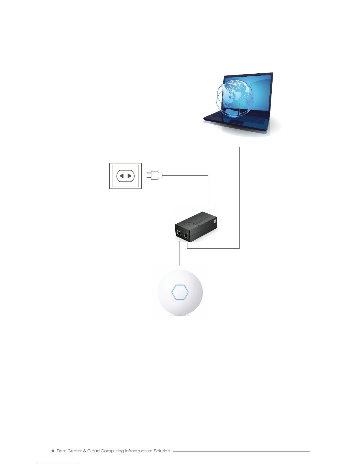
Installation Diagram
Solution 1
Data Center & Cloud Computing Infrastructure Solution
POE POWER SUPPLY
AP
Internet
Page 4
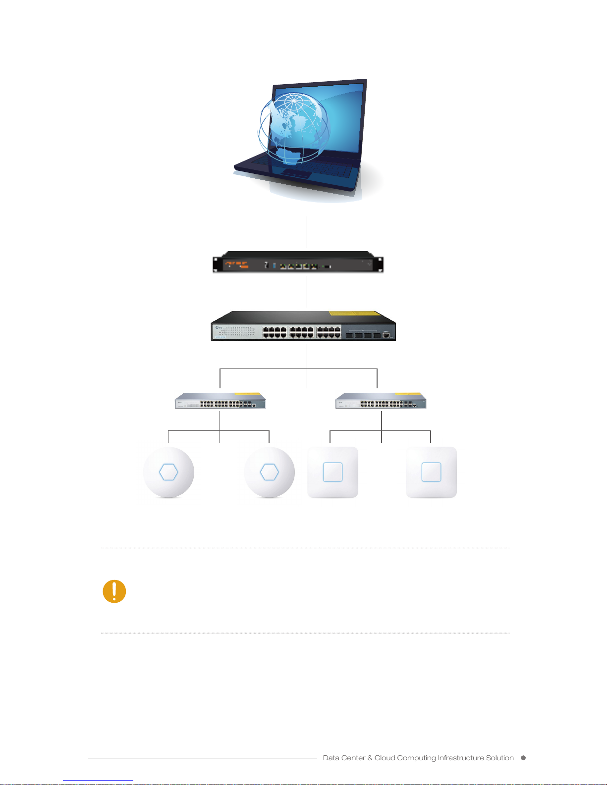
Solution 2
Data Center & Cloud Computing Infrastructure Solution
Note: Solution 1 (Single Device Setting): Get into the web setting page
independently.
Solution 2 (Multiple Devices Setting): Do centralized management settings
and local portal by AC core gateway. (POE power supply and other devices
are not standard, please refer to the packing list. )
……
…………
AP AP AP AP
Internet
AC CORE GATEWAY
CORE SWITCH
POE SWITCH POE SWITCH
Page 5
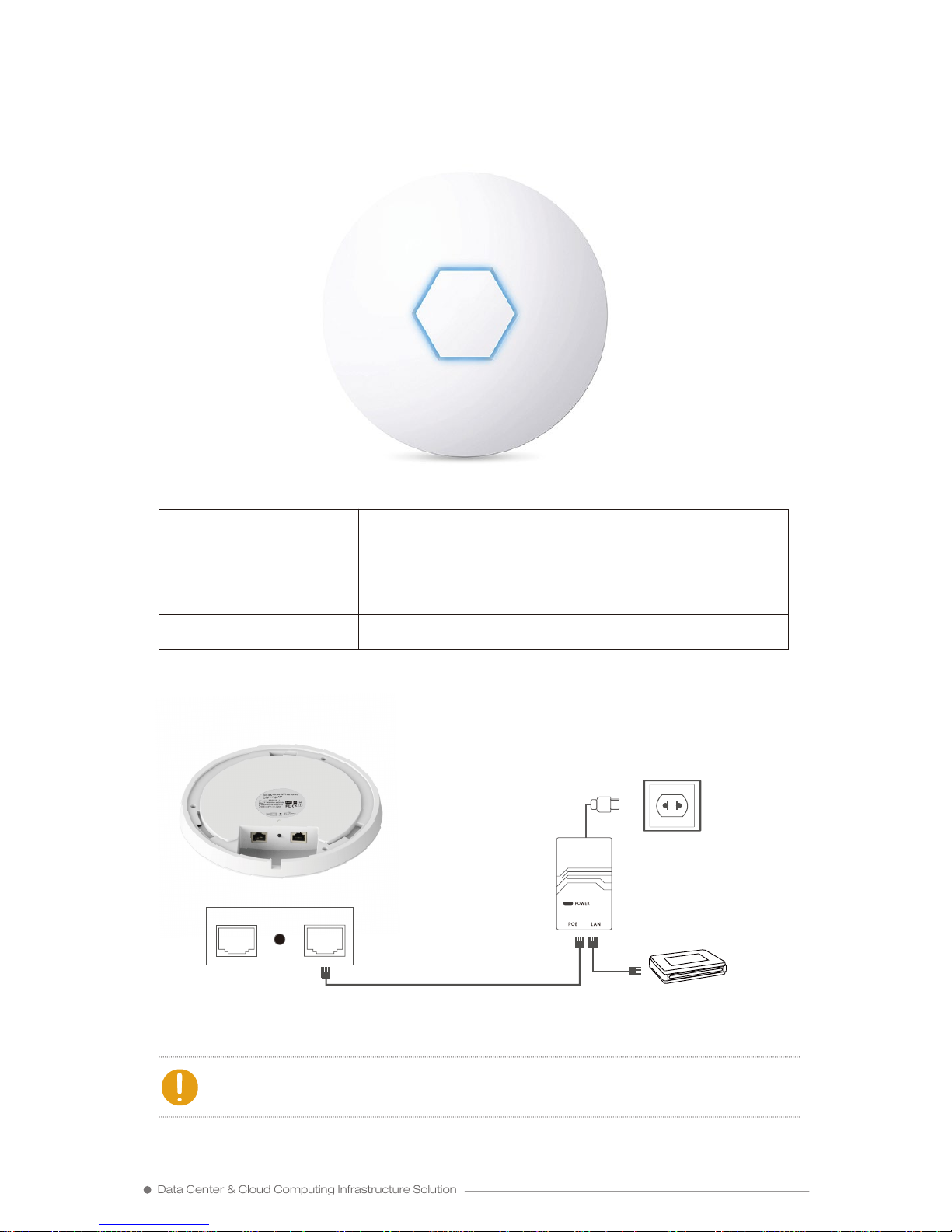
Connection Diagram
Note: Set the LAN port of the device to the computer.
POE Power Supply
(Not Standard)
Higher Level Network
LAN RESET WAN
LED Color States
White Power on
Red WAN port connected
Blue Wifi signal received
Hardware Overview
LED
Data Center & Cloud Computing Infrastructure Solution
Page 6
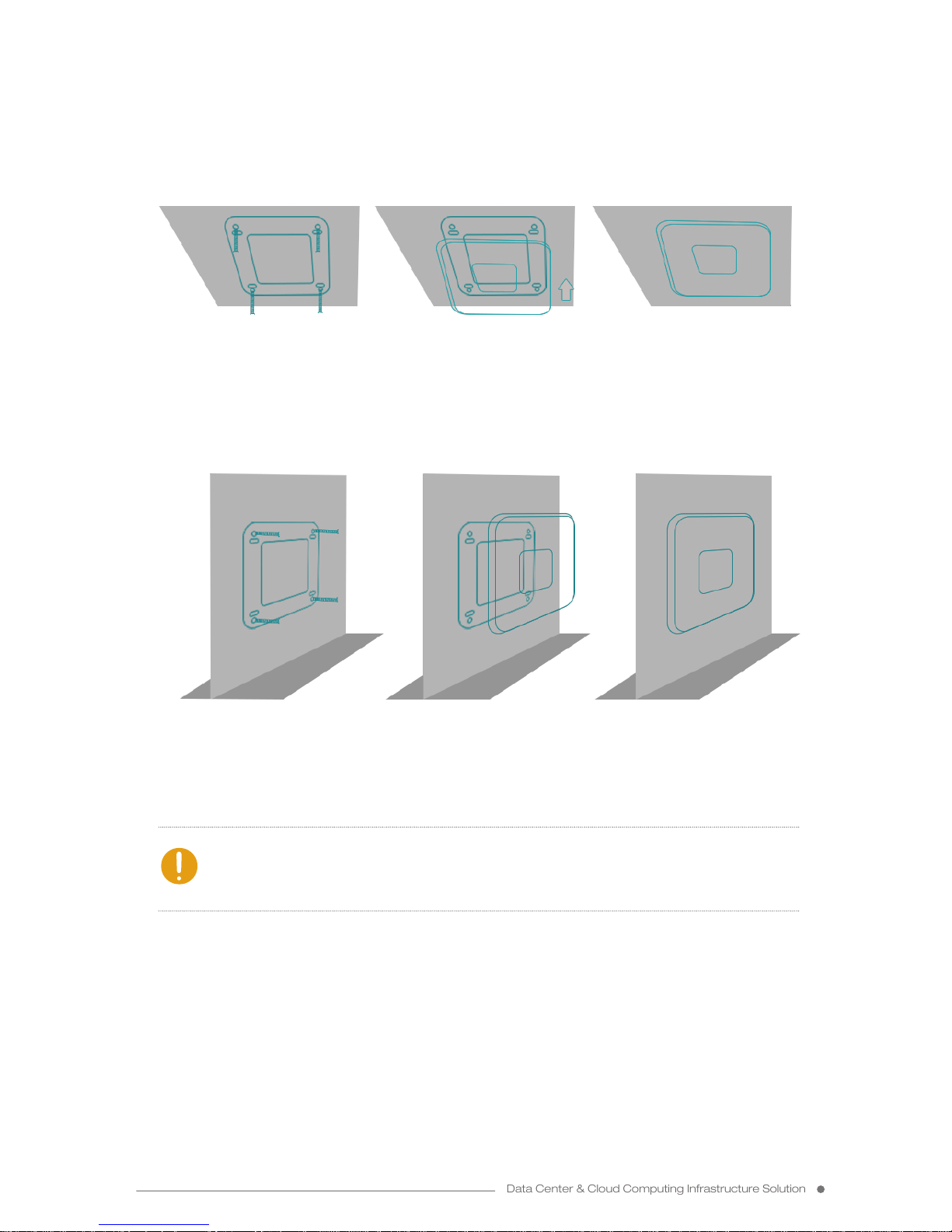
Installation Diagram
Ceiling Installation
Wall Installation
② let the AP and chassis
docking
③ installation over① the chassis is removed,
whichis fixed on the chiling
with four screws
② let the AP and chassis
docking
③ installation over① the chassis is removed,
whichis fixed on the wall
with four screws
Note: This quick installation guide is taken the circled ceiling AP for an
example. Some of square ceiling AP have 4 screws and please push one
side to install.
ceiling
wall wall wall
ceiling ceiling
Data Center & Cloud Computing Infrastructure Solution
Page 7
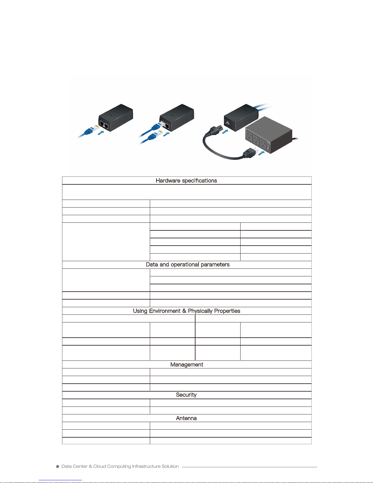
The single-pack of the Wireless AP includes one Gigabit PoE adapter. For
multi-pack units, we recommend using a Switch.
1. Connect the Ethernet cable from the Wireless AP to the adapter’s POE port.
2. Connect an Ethernet cable from your LAN to the adapter’s LAN port.
3. Connect the Power Cord to the adapter‘s power port. Connect the other end
of the Power Cord to a power outlet.
Data Center & Cloud Computing Infrastructure Solution
Connecting Power over Ethernet
Specifications:
Hardware specifications
Frequency Range & Channels:
ATHEROS AR9341 533MHZ RF 64MB DDR 16M Flash (The New Chip)
2.4~2.4835GHz;20MHz,40MHz
RF Power Output:
Modulation Mode:
24dBm
Response Rate:
DBPSK,DQPSK,CCK,OFDM,16-QAM,64-QAM
300M: -68dBm@10%PER
270M: -68dBm@10%PER
130M: -68dBm@10%PER
54M: -85dBm@10%PER 11M: -85dBm@10%PER
108M: -68dBm@10%PER
1M: -90dBm@10%PER
6M: -88dBm@10%PER
Data and operational parameters
802.11n: 6.5-300Mbps
802.11g: 6/9/12/18/24/36/48/54/108Mbps
Support Protocols:
Auto transmission rate selection:
Support WLAN Standards:
802.11b: 1/2/5.5/11Mbps
IEEE 802.11b/g/n, IEEE 802.3u, IEEE 802.3af
FS/CA, TCP/IP, IPX/SPX, NetBEUI, DHCP, NDIS3/4/5
Working Temperature:
Using Environment
Using Environment & Physically Properties
Physically Properties
Storage Temperature:
-50°C~80°C
Product Size:
Humidity(Non Condensing):
Package
Size:
Product
Weight:
0.855KG(Net) /
1.24KG(Gross)
≤95%
-30°C~65°C
350x250x90(mm)
205x205x38.5(mm)
Management
Based on WEB Management:
Support
SNMP MIB:
Support
Telnet: Support
MAC Address Control: Support
Encryption:
Support 64/128 bits WEP, WPA, WPA2, 802.1X
2.4~2.4835GHz
Vertical, Horizontal
5dBiAntenna Gain:
Polarization Mode:
Frequency Range:
Antenna
Security
Page 8
1. Compliance is required with respect to voltage, frequency, and current
requirements indicated on the manufacturer’s label. Connection to a different
power source than those specified may result in improper operation, damage to
the equipment or pose a fire hazard if the limitations are not followed.
2. There are no operator serviceable parts inside this equipment. Service should
be provided only by a qualified service technician.
3. This equipment is provided with a detachable power cord which has an integral
safety ground wire intended for connection to a grounded safety outlet.
a. Do not substitute the power cord with one that is not the provided approved
type. Never use an adapter plug to connect to a 2-wire outlet as this will defeat
the continuity of the grounding wire.
b. The equipment requires the use of the ground wire as a part of the safety
certification, modification or misuse can provide a shock hazard that can result
in serious injury or death.
c. Contact a qualified electrician or the manufacturer if there are questions about
the installation prior to connecting the equipment.
d. Protective earthing is provided by Listed AC adapter. Building installation shall
provide appropriate short-circuit backup protection.
e. Protective bonding must be installed in accordance with local national wiring
rules and regulations.
Data Center & Cloud Computing Infrastructure Solution
Safety Notices
Electrical Safety Information
1. Read, follow, and keep these instructions.
2. Heed all warnings.
3. Only use attachments/accessories specified by the manufacturer.
WARNING: Do not use this product in location that can be submerged by
water.
WARNING
WARNING: Avoid using this product during an electrical storm. There may
be a remote risk of electric shock from lightning.
WARNING
Page 9

The above warranty does not apply if the Product:
1. Has been modified and/or altered, or an addition made thereto, except by the
personnel outside the company's authorized representative or without the written
permission of the company.
2. Has been painted, rebranded or physically modified in any way;
3. Has been damaged due to errors or defects in cabling;
4. Has been subjected to misuse, abuse, negligence, abnormal physical,
electromagnetic or electrical stress, including lightning strikes, or accident;
5. Has been damaged or impaired as a result of using third party firmware;
6. Has not been received by the company within 30 days of issuance of the RMA.
In addition, the above warranty shall apply only if: the product has been properly
installed and used at all times in accordance, and in all material respects, with the
applicable Product documentation; all Ethernet cabling runs use CAT5 (or above),
and for outdoor installations, shielded Ethernet cabling is used, and for indoor
installations, indoor cabling requirements are followed.
Returns
No Products will be accepted for replacement or repair without obtaining a
Return Materials Authorization (RMA) number from the company during the
warranty period, and the Products being received at the company's facility freight
prepaid in accordance with the RMA process of the company. Products returned
without an RMA number will not be processed and will be returned freight collect
or subject to disposal.
Data Center & Cloud Computing Infrastructure Solution
The company warrants that the products (hereinafter referred to as “the
products") shall not be defective in materials and workmanship within one (1)
year from the date of delivery, in accordance with the products provided below
(hereinafter referred to as “products") under normal use and operation. In
accordance with the foregoing guarantee, the sole obligation and responsibility
of the company is to repair or replace any product that does not conform to the
guarantee contents in the above warranty period according to its judgment. This
warranty does not include the removal and reinstallation of any product. The
warranty period of the product after repair or replacement shall not exceed its
initial warranty period.
Limited Warranty
Warranty Conditions
Page 10

Data Center & Cloud Computing Infrastructure Solution
Changes or modifications not expressly approved by the party responsible
for compliance could void the user’s authority to operate the equipment.
This device complies with Part 15 of the FCC Rules. Operation is subject to
the following two conditions.
1. This device may not cause harmful interference, and
2. This device must accept any interference received, including
interference that may cause undesired operation.
This equipment has been tested and found to comply with the limits for a
Class B digital device, pursuant to Part 15 of the FCC Rules. These limits are
designed to provide reasonable protection against harmful interference in
a residential installation. This equipment generates, uses and can radiate
radio frequency energy and, if not installed and used in accordance with
the instructions, may cause harmful interference to radio communications.
However, there is no guarantee that interference will not occur in a
particular installation. If this equipment does cause harmful interference
to radio or television reception, which can be determined by turning
the equipment off and on, the user is encouraged to try to correct the
interference by one or more of the following measures:
• Reorient or relocate the receiving antenna.
• Increase the separation between the equipment and receiver.
• Connect the equipment into an outlet on a circuit different from that to
which the receiver is connected.
• Consult the dealer or an experienced radio/TV technician for help.
Operations of this equipment in a residential area is likely to cause
harmful interference in which case the user will be required to correct the
interference at his own expense.
This radio transmitter (FCC: SWX-UAPACL) has been approved by FCC
to operate with the antenna types listed below with the maximum
permissible gain and required antenna impedance for each antenna type
indicated. Antenna types not included in this list, having a gain greater
than the maximum gain indicated for that type, are strictly prohibited for
use with this device.
Antenna Information: Dual-band antenna, Gain: 3 dBi
Compliance
FCC
Page 11

Data Center & Cloud Computing Infrastructure Solution
CE marking on this product represents the product is in compliance with all
directives that are applicable to it.
Alert Sign (!) Follows CE Marking
Alert sign must be indicated if a restriction on use applied to the product
and it must follow the CE marking.
The antennas used for this transmitter must be installed to provide a
separation distance of at least 20 cm from all persons and must not be
located or operating in conjunction with any other antenna or transmitter.
RF Exposure Warning
CE Marking
European Directive 2002/96/EC requires that the equipment bearing
this symbol on the product and/or its packaging must not be disposed
of with unsorted municipal waste. The symbol indicates that this
product should be disposed of separately from regular household waste
streams. It is your responsibility to dispose of this and other electric and
electronic equipment via designated collection facilities appointed by the
government or local authorities. Correct disposal and recycling will help
prevent potential negative consequences to the environment and human
health. For more detailed information about the disposal of your old
equipment, please contact your local authorities, waste disposal service, or
the shop where you purchased the product.
RoHS/WEEE Compliance Statement
Page 12

Contact Us
Room 2702, Yisibo Software Building,
Xinhaiyi, No.2 Haitian Road, Yuehai
Street, Nanshan, District, Shenzhen, China
Tel: +86(755)83571351
820 SW 34th Street Bldg W7
Suite H, Renton, WA 98057,
United States
Tel: +1 (877) 205 5306
China North America
1220 Tung Chun Commercial
Centre, Shanghai Street 438-444,
Kowloon, HongKong
Tel: +(852) 5808 7203
Building 7, NOVA Neufahrn Gewer
bepark, Am Gfild7, 85375,
Neufahrn bei Freising, Munich
Tel: +49 (0) 89 414176412
Hong Kong
Germany
Addresses, phone number and fax number also have been listed at www.fs.com.
Please e-mail us at [email protected] or call us for assistance. All statements,
technical information, and recommendations related to the products here are
based upon information believed to be reliable or accurate. However, the
accuracy or completeness thereof is not guaranteed, and no responsibility is
assumed for any inaccuracies. Please contact FS for more information.
 Loading...