

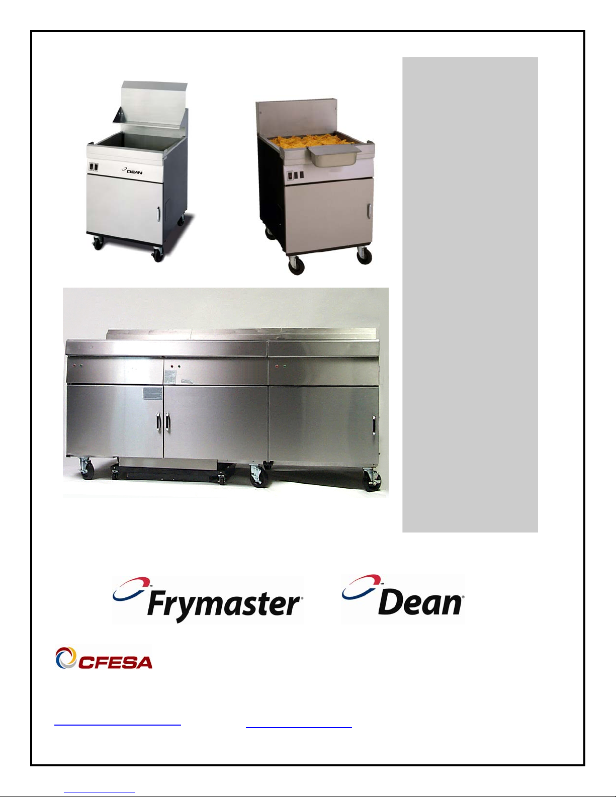
Flatbottom Gas Fryers
YSCFC24G Series
Service & Parts Manual
Models YSCFC 1824G, 2424G, and 24/24/15 Systems
with Built-In Filtration
Frymaster Dean, a member of the Commercial Food Equipment Service Association,
recommends using CFESA Certified Technicians.
PRINTED IN THE USA
service@frymaster.com
24-Hour Service Hotline
1-800-551-8633
www.frymaster.com
FEBRUARY 2009
*8196472*
Please read all sections of this manual and retain for future reference.
This product has been certified as commercial cooking equipment and MUST be installed by
professional personnel as specified. Installation, maintenance and repairs should be performed
by your FRYMASTER DEAN FACTORY AUTHORIZED SERVICE CENTER.
DANGER
Do not store or use gasoline or other flammable vapors and liquids in the vicinity of this or any
other cooking appliance.
DANGER
Instructions explaining procedures to be followed MUST be posted in a prominent location in
the event the operator detects a gas leak. This information can be obtained from the local gas
company or gas supplier.
WARNING
Improper installation, adjustment, alteration, service or maintenance can cause property
damage, injury or death. Read the installation, operating and maintenance instructions
thoroughly before installing or servicing this equipment.
DANGER
Safe and satisfactory operation of your equipment depends on proper installation. Installation
MUST conform with local codes, or in absence of local codes, with the National Fuel Gas Code,
ANSI Z223.1; The Natural Gas Installation Code, CAN/CGA-B149.1; The Propane Installation
Code, CAN/CGA-B149.2; or The latest edition of the National Electric Code, N.F.P.A. 70.
NOTICE
IF, DURING THE WARRANTY PERIOD, THE CUSTOMER USES A PART FOR THIS ENODIS
EQUIPMENT OTHER THAN AN UNMODIFIED NEW OR RECYCLED PART PURCHASED
DIRECTLY FROM FRYMASTER DEAN, OR ANY OF ITS AUTHORIZED SERVIC E CENTERS,
AND/OR THE PART BEING USED IS MODIFIED FROM ITS ORIGINAL CONFIGURATION, THIS
WARRANTY WILL BE VOID. FURTHER, FRYMASTER DEAN AND ITS AFFILIAT ES WILL NOT BE
LIABLE FOR ANY CLAIMS, DAMAGES OR EXPENSES INCURRED BY THE CUSTOMER WHICH
ARISE DIRECTLY OR INDIRECTLY, IN WHOLE OR IN PART, DUE TO THE INSTALLATION OF
ANY MODIFIED PART AND/OR PART RECEIVED FROM AN UNAUTHORIZED SERVICE CENTER.
DANGER
The crumb tray in fryers equipped with a filter system must be emptied into a fireproof container
at the end of frying operations each day. Some food particles can spontaneously combust if left
soaking in certain shortening material. Additional information can be obtained in the filtration
manual included with the system.
DANGER
The front ledge of the fryer is not a step. Do not stand on the fryer. Serious injury can result
from slips or contact with the hot oil.
WARNING
Drawings and photos used in this manual are intended to illustrate operational, cleaning and
technical procedures and may not conform to on-site management operational procedures.
WARNING
No structural material on the fryer should be altered or removed to accommodate placement of
the fryer under a hood. Questions? Call the Frymaster Dean Service Hotline at 1-800-551-8633.
This equipment is to be installed in compliance with the basic plumbing code of The Building
Officials and Code Administrators International, Inc. (BOCA) and the Food Service Sanitation
Manual of the Food and Drug Administration.
COMPUTERS (WHERE APPLICABLE)
FCC
This device complies with Part 15 of the FCC rules. Operation is subject to the following two conditions:
1) This device may not cause harmful interference, and 2) This device must accept any interfere nce
received, including interference that may cause undesired operation. While this device is a verified Class
A device, it has been shown to meet the Class B limits.
CANADA
This digital apparatus does not exceed the Class A or B limits for radio noise emissions as set out by the
ICES-003 standard of the Canadian Department of Communications.
Cet appareil numerique n’emet pas de bruits radioelectriques depassany les limites de classe A et B
prescrites dans la norme NMB-003 edictee par le Ministre des Communcations du Canada.
DANGER
THIS PRODUCT CONTAINS CHEMICALS KNOWN TO THE STATE OF CALIFORNIA TO CAUSE
CANCER AND/OR BIRTH DEFECTS OR OTHER REPRODUCTIVE HARM.
Operation, installation, and servicing of this product could expose you to airborne particles of
glasswool or ceramic fibers, crystalline silica, and/or carbon monoxide. Inhalation of airborne
particles of glasswool or ceramic fibers is known to the State of California to cause cancer.
Inhalation of carbon monoxide is known to the State of California to cause birth defects or other
reproductive harm.
Do not bang fry baskets or other utensils on the fryer’s joiner strip. The strip is present to seal
the joint between the fry vessels. Banging fry baskets on the strip to dislodge shortening will
distort the strip, adversely affecting its fit. It is designed for a tight fit and should only be
WARNING
removed for cleaning.

YSCFC Series Flatbottom Gas Fryers
Service & Parts Manual
TABLE OF CONTENTS
PAGE #
1.
1.1
1.2
1.3
1.4
1.5
1.6
1.6.1
1.6.2
1.6.3
1.6.4
1.6.5
1.6.6
1.7
1.7.1
1.7.2
1.7.3
1.7.4
1.7.5
1.8
1.8.1
1.8.2
1.9
1.9.1
1.9.2
1.9.3
SERVICE PROCEDURES
Functional Description
Accessing Fryers for Servicing
Cleaning Gas Valve Vent Tube
Adjusting Burner Manifold Gas Pressure
Calibrating the Thermatron Temperature Controller
Replacing Fryer Components
Remove/Replace Temperature Probe or High-Limit Thermostat
Removing/Replacing Rocker Switches
Replacing the Gas Valve
Replacing the Direct Spark Ignitor
Removing/Replacing Blower Assembly or Air Prover Switch
Replacing the Frypot
Troubleshooting and Problem Isolation
Ignition Failures
Improper Burner Functioning
Improper Temperature Control
Filtration Problems
Leakage
Troubleshooting Guides
Main Burner Malfunctions
Indicator Lights
Wiring Diagrams
Wiring for Common Cabinet Flatbottom without Boil Out
24/24 Filter Wiring
18/24 Common Cabinet Transformer Box
1–1
1–1
1–3
1–4
1–4
1–5
1–6
1–6
1–8
1–9
1–9
1–10
1–11
1–15
1–16
1–17
1–19
1–19
1–21
1–22
1–22
1–23
1–24
1–24
1–25
1–26
YSCFC Series Flatbottom Gas Fryers
Service & Parts Manual
TABLE OF CONTENTS (cont.)
PAGE #
2.
2.1
2.2
2.3
2.4
2.5
2.6
2.7
2.8
2.9
2.10
2.11
2.12
PARTS LIST
Blower Assembly, Combustion Air
Burner Manifold and Related Components
Flue Caps, Top Caps, and Related Components
Cabinetry
Door Assemblies and Component Parts
Control Panels, Wireways, and Related Components
Oil Return and Suction Manifold
Filter Unit
Frypot, Drain, and Oil Return Components
Drain Valve and Components
Wiring Connectors, Pin Terminals, and Power Cords
Screws, Nuts, Fasteners
2–1
2–1
2–2
2–4
2–6
2–8
2–9
2–11
2–13
2–14
2–16
2–17
2–18

YSCFC SERIES FLATBOTTOM GAS FRYERS
CHAPTER 1: SERVICE PROCEDURES
1.1 Functional Description
YSCFC Series Flatbottom gas fryers contain a welded steel frypot (mild steel) with heat-transfer
ducting on the frypot bottom for efficient heating of oil without scorching. A draft inducer draws air
over the burners for combustion. Air movement directs the combustion products back and forth
across the frypot bottom by means of a set of baffles, transferring the heat evenly. Cold air is
prevented from entering the combustion chamber and cooling the oil during the coasting cycle.
Flames originate from orifices in three tubular burners positioned beneath the frypot. The diameter
of the orifices differs for Natural (CE:G20/G25) and LP (CE:G31) gas as indicated in the table
below.
NON-CE (Altitudes of 2000 feet or less)
MODEL
1824/24YSCFC 120
INPUT
(BTU)
GAS TYPE
NAT
LP
ORIFICE
[DRILL SIZE (MM)]
#34 (2.82)
#50 (1.78)
ORIFICE
PART #
810-2051
810-2317
QTY
3
3
An electromechanical gas valve regulates gas flow to the manifold. YSCFC Series Flatbottom gas
fryers are equipped with a 24-volt valve system and an electronic ignition system (direct spark
ignition).
Electronic Ignition Configuration
In units configured for electronic ignition, an ignition module connects to an ignitor assembly. The
ignition module performs three important functions: it provides an ignition spark, supplies voltage to
the gas valve, and proofs the burner flame.
The module contains a time delay circuit and a coil that activates the gas valve. The ignitor
assembly consists of a spark plug and a flame sensor element.
At start-up the ON/OFF switch is placed in the "ON" position, supplying 115 VAC or 230 VAC,
according to system configuration, to the Thermatron interface board. The voltage is stepped down
via transformer to 24 VAC before entering the ignition module. If resistance in the temperature
probe indicates the temperature in the frypot is below 150°F (66°C), the current flows through a melt
cycle circuit where a switch alternately closes for approximately 4 seconds and opens for
approximately 20 seconds. If the temperature is 150°F (66°C) or above, the current flows through a
heat circuit, bypassing the timer switch. In either case, current is supplied to the other leg of the heat
relay coil, which then closes an electronic switch in the 24 VAC circuit to provide current to the
ignition module.
Circuitry in the ignition module sends 24 VAC current to the gas valve via a normally closed highlimit switch and a drain safety switch. Simultaneously, the module causes the ignitor to spark for up
EQUIPMENT
PRESSURE
MBAR INCH W.C.
10
27.5
4
11
1-1
YSCFC SERIES FLATBOTTOM GAS FRYERS
CHAPTER 1: SERVICE PROCEDURES
to 11 seconds to light the burner flame. A flame sensor verifies that the burner is lit by measuring
the flow of microamps through the flame. If the burner does not light (or is extinguished), current to
the ignition module is interrupted, preventing the main valve from opening, and the ignition module
"locks out" until the power switch is turned "OFF", then back "ON".
A temperature probe monitors the temperature in the frypot. When the programmed setpoint
temperature is reached, resistance in the probe causes the heat cycle circuitry in the controller to
interrupt current flow through the heat relay. This in turn interrupts the 24 VAC to the ignition
module, resulting in closure of the gas valve.
Control Options
YSCFC Series Flatbottom gas fryers are equipped with Thermatron temperature controller. The
fryer is turned on and off by means of a rocker switch and the temperature is set by adjusting a
potentiometer. The Thermatron board is located in the wireway box behind the control panel, or in a
component box inside the cabinet (depending on fryer configuration).
The Thermatron temperature controller operates by comparing resistance between the potentiometer
setting and the temperature probe. If the resistance values don’t match, an on-board relay energizes,
sending voltage to the gas valve that supplies fuel to the burners. When the resistance values are
equal, the on-board relay de-energizes, interrupting voltage to the gas valve, which stops the fuel
flow.
Depending on the system configuration and destination, 115VAC controller boards are used.
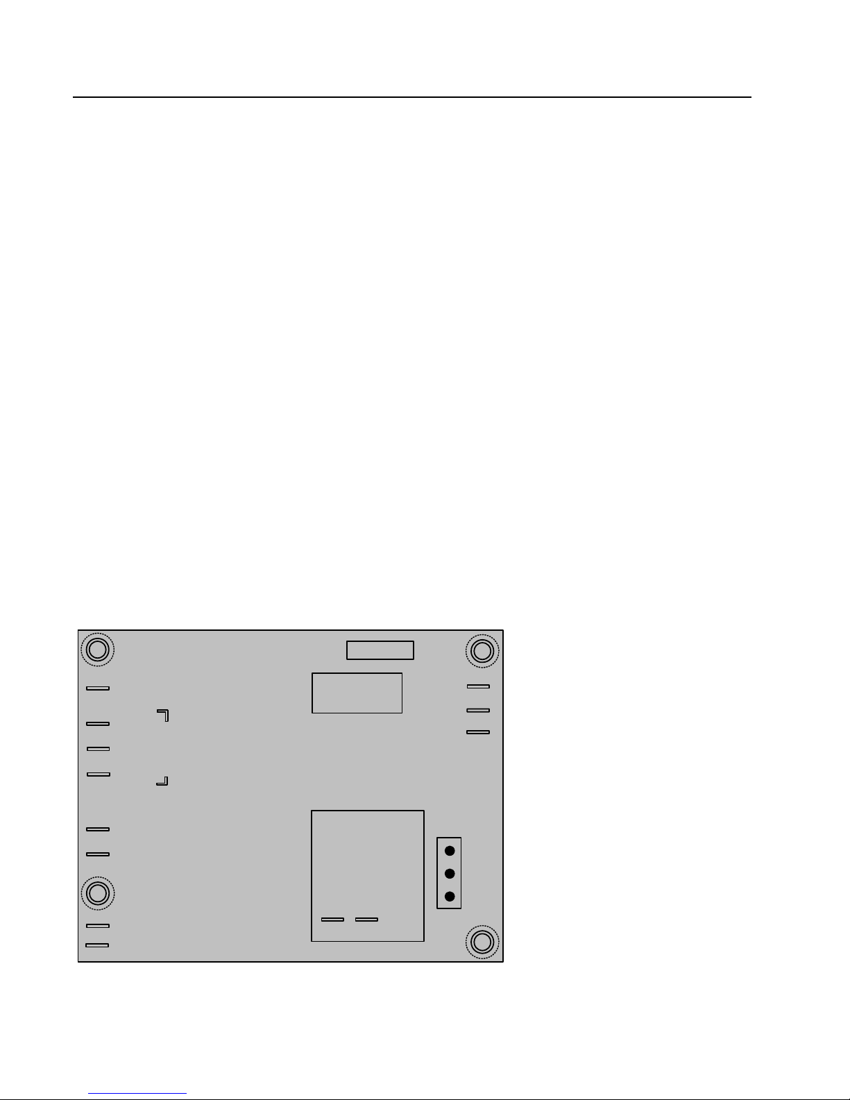
Line voltage enters the interface
board at J1. The temperature controls
(potentiometer) are connected to
terminals 7, 8 and 9. The sensor
probe circuit is connected to
terminals 10 and 11. The high-limit
and gas valve route through terminal
12. Terminals 5 and 6 are the melt-
BOIL
9
8
7
CCW
CT
CW
EXT POT
K1
3 AMP FUSE
F1
REMOVABLE
RELAY
COM
NC
NO
13
14
12
cycle disable circuit. The melt cycle
is enabled unless terminals 5 and 6
11
PROBE
10
5
MELT CYCLE DISABLE
6
P12 P13
12/24 VAC INPUT
J1
COM
115
230
are jumped out.
Thermatron Controller Board
1-2
YSCFC SERIES FLATBOTTOM GAS FRYERS
CHAPTER 1: SERVICE PROCEDURES
Safety Components
All YSCFC Series Flatbottom gas fryers are equipped with a high-limit thermostat. In the event that
the fryer fails to properly control the oil temperature, the high-limit thermostat prevents the fryer
from overheating to flash point. The high-limit thermostat acts as a normally closed power switch
that opens when exposed to temperatures above 410°F [(210°C) - CE] to 450°F [(232°C) - Non-CE].
CE and non-CE high-limits are not interchangeable.
Frying systems with built-in filtration are equipped with drain microswitches that disable the fryer if
the drain valves are not completely closed. Opening a drain valve (i.e. filtering or draining the fryer)
automatically opens the reset switch circuit. The drain valve must be fully closed prior to resetting
the safety switch.
1.2 Accessing Fryers for Servicing
DANGER
Moving a fryer filled with cooking oil/shortening may cause spilling or splattering of
the hot liquid. Follow the draining instructions included with the fryer before
attempting to relocate a fryer for servicing.
NOTE: Perform the following only if the fryer cannot be serviced in its installed location. Some of
the following service procedures require the fryer to be connected to the gas and/or electrical supply.
1. Shut off the gas supply to the unit. Unplug the power cords. Remove any attached restraining
devices.
2. Disconnect the unit from the gas supply.
3. Relocate the fryer for service accessibility.
4. After servicing is complete, reconnect the unit to the gas supply, reattach restraining devices, and
plug in the electrical cords.
1-3
YSCFC SERIES FLATBOTTOM GAS FRYERS
CHAPTER 1: SERVICE PROCEDURES
1.3 Cleaning the Gas Valve Vent Tube (if applicable)
1. Set the fryer power switch and the gas valve to the "OFF" position.
2. Carefully unscrew the vent tube from the gas valve. NOTE: The vent tube may be straightened
for ease in removal.
3. Pass a piece of wire through the tube to remove any obstruction. Remove the wire and blow
through the tube to ensure it is clear.
4. Reinstall tube and bend so that the opening is pointing downward.
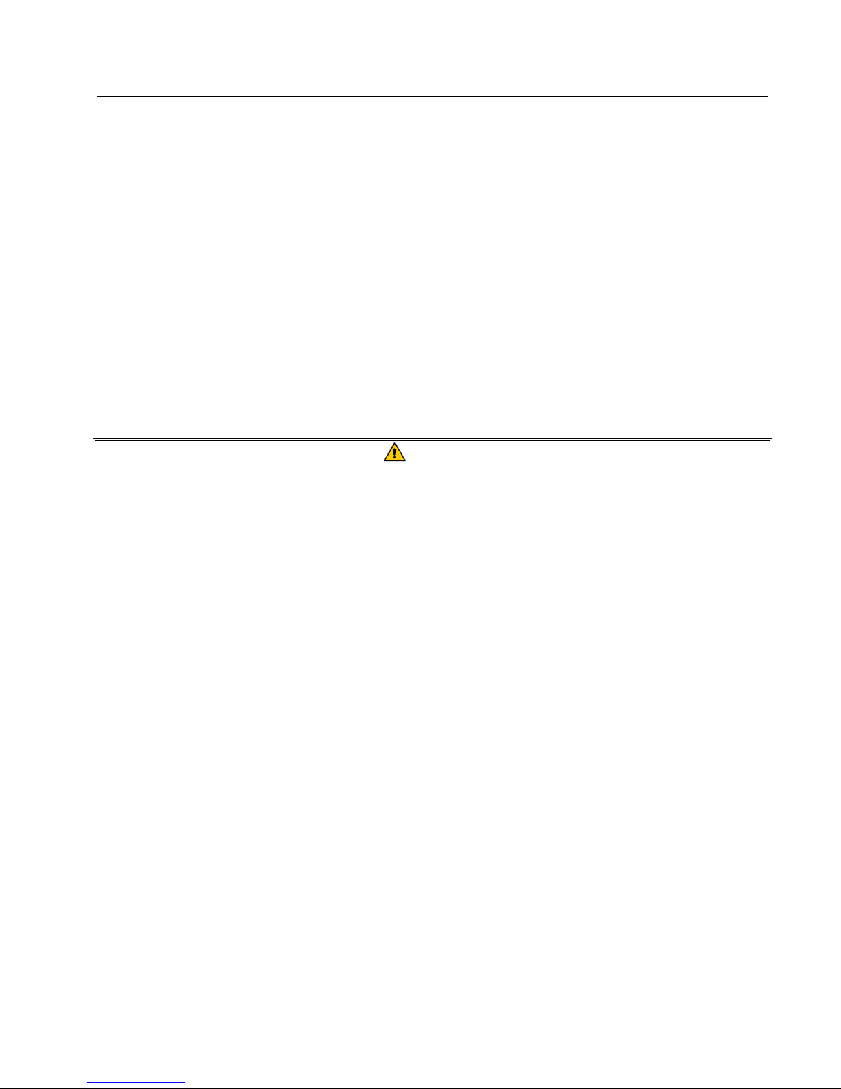
1.4 Adjusting Burner Manifold Gas Pressure
WARNING
This task should be performed by qualified service personnel only.
1. Ensure that the gas valve knob is in the
"OFF" position.
2. Remove the pressure tap plug from the
burner manifold.
3. Insert the fitting for a gas pressuremeasuring device into the pressure tap
hole.
Remove pressure tap from burner manifold to
check burner manifold pressure.
4. Place the gas valve in the "ON" position then place the fryer power switch in the "ON" position.
When the burner lights and continues to burn, note gas pressure reading for correct pressure in
accordance with the table on page 1-1.
1-4
YSCFC SERIES FLATBOTTOM GAS FRYERS
CHAPTER 1: SERVICE PROCEDURES
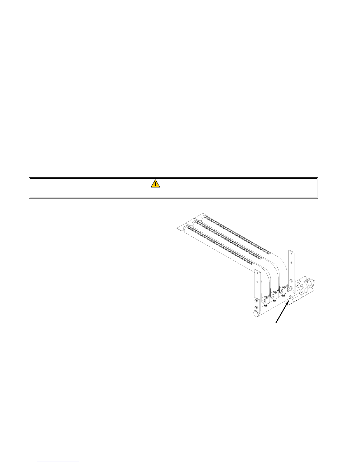
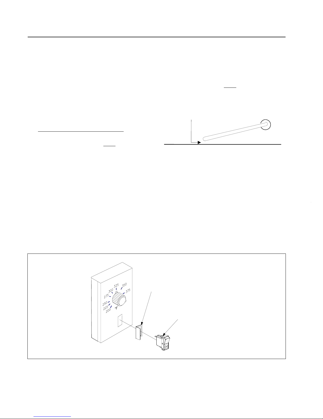
5. To adjust burner gas pressure, remove the cap from the gas valve
regulator and adjust to correct p ressure (arrow shown at right).
6. Place the fryer power switch and the gas valve in the "OFF"
position. Remove the pressure-measuring device fitting from
the pressure tap hole and reinstall the pressure tap plug.
1.5 Calibrating the Thermatron Temperature
Controller
1. Ensure the fryer ON/OFF switch is in the "OFF" position. Fill the
frypot to the proper oil-level line with cooking oil/shortening. If
solid shortening is used, ensure that the shortening is properly
packed and melted in the frypot before proceeding.
2. Place the fryer ON/OFF switch in the "ON" position. Set the Thermatron dial to 325°F (162°C).
3. Allow the oil/shortening to stabilize at setpoint temperature. This is evident when the burners
have cycled on and off several times.
4. Insert a thermometer or pyrometer into the frypot within ½ inch (1.25 cm) of the probe tip.
Ensure the tip of the thermometer/pyrometer does not touch the bottom or sides of the frypot.
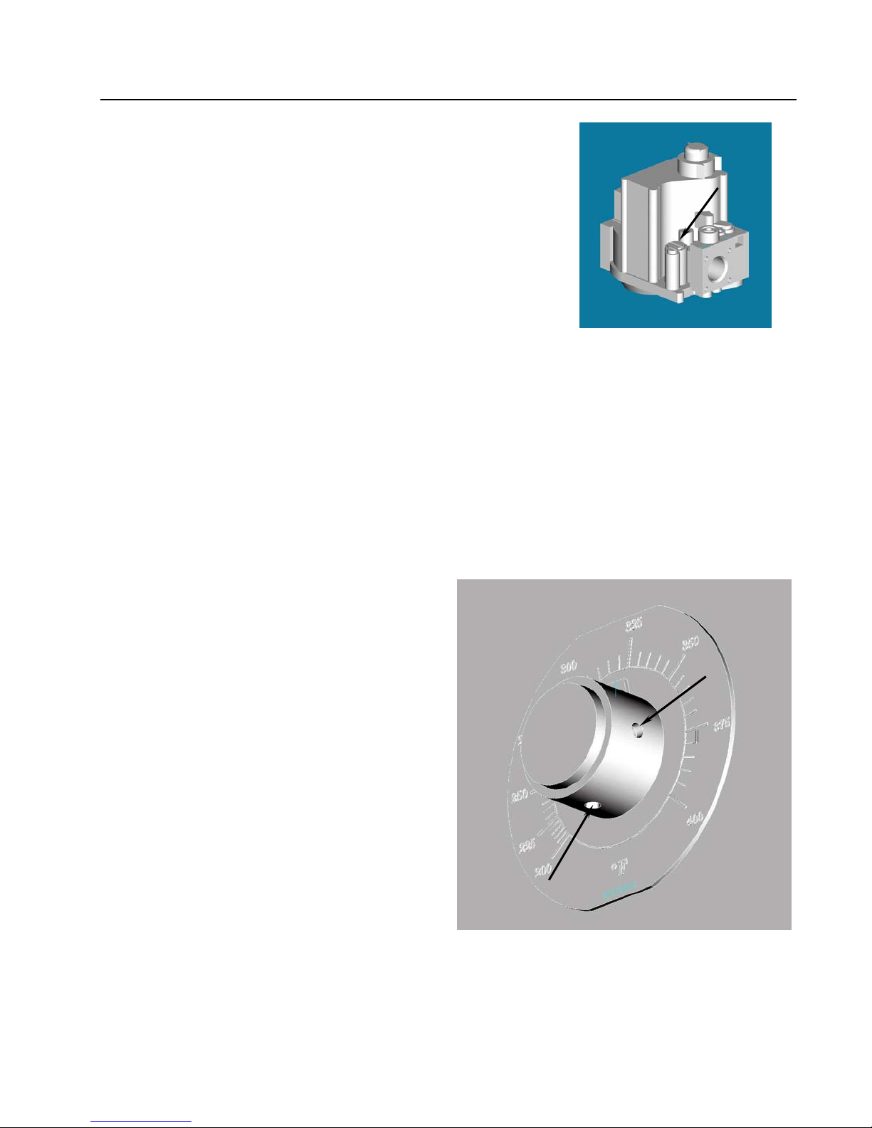
5. If the temperature on the thermometer is
higher or lower than 325°F (162°C), the
dial is out of calibration.
6. Calibrate the dial by first loosening two
setscrews in the dial (arrows). After loosening
both setscrews, slowly turn the dial to match
the temperature reading of the thermometer.
Tighten each setscrew, ensuring the dial does
not move on the shaft during tightening.
7. Allow burners to cycle on and off several
times, then recheck oil temperature as
described in step #5. If the Thermatron
dial temperature matches the thermometer
temperature, the controller is calibrated.
If not, repeat step #7.
8. After calibration is complete, place the fryer
power switch in the "OFF" position and
Loosen two setscrews in dial (arrows) to recalibrate
controller.
disconnect the fryer from the electrical supply.
Non-CE Electronic Ignition
Valve
1-5
YSCFC SERIES FLATBOTTOM GAS FRYERS
CHAPTER 1: SERVICE PROCEDURES
1.6 Replacing Fryer Components
1.6.1 Remove/Replace Temperature Probe or High-Limit Thermostat
1. Disconnect the fryer from the electrical supply.
2. Allow the frypot to cool for 10 minutes before draining. Drain cooking oil/shortening from the
frypot. Allow the frypot to cool completely before proceeding.
3. Remove the fryer door(s) for access to control panel screws. Lift door up, disengage rod from
lower door bracket, and then remove door. (Current production models have spring-loaded door
pins. Disengage bottom pin from the hinge, and then remove door.)
4. Remove the marine edge (where applicable) from the topcap.
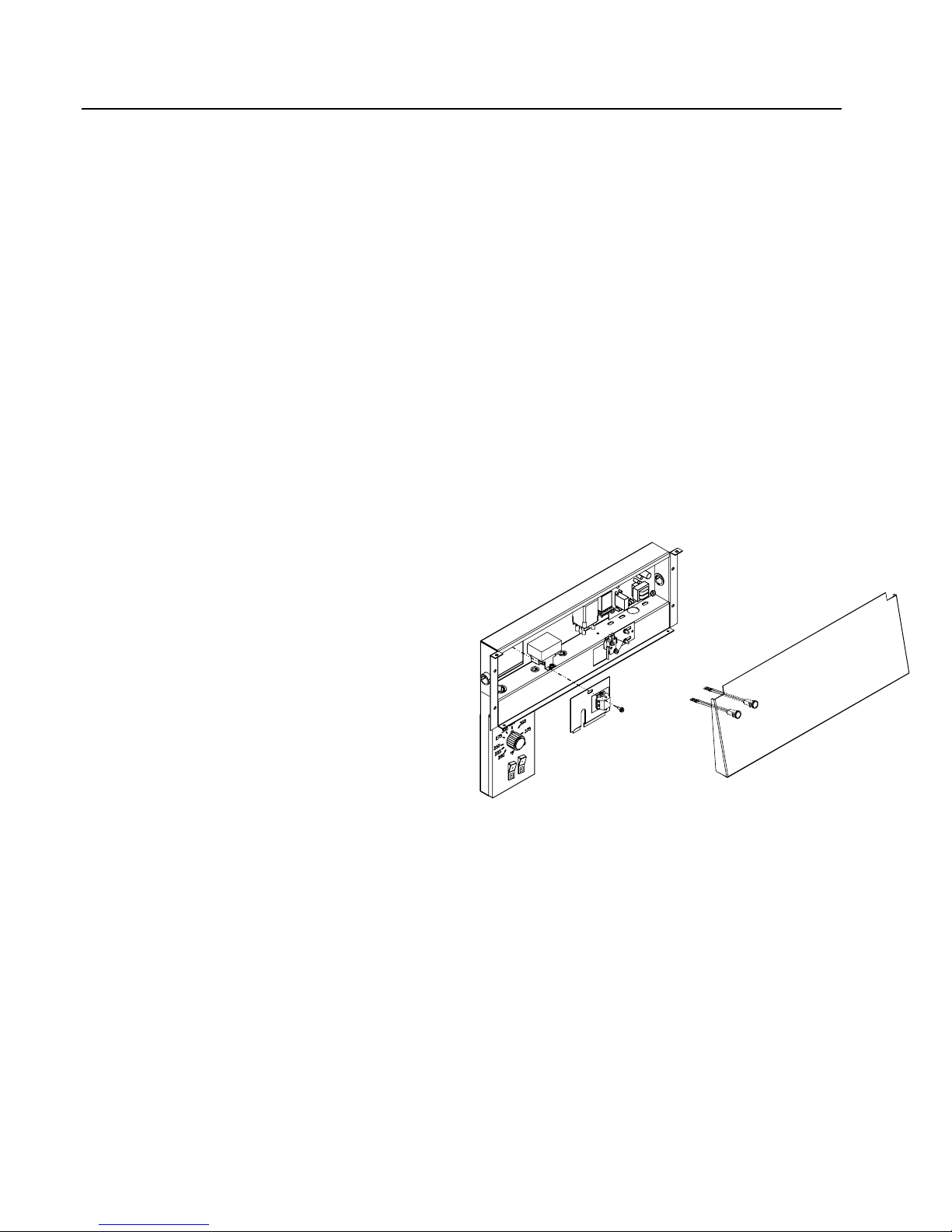
5. Support the control panel and remove
screws securing the panel to the wireway
box. Remove the control panel.
6. On units with indicator lights on the control
panel, mark and unplug the wiring, and then
remove the control panel.
7. Remove screw securing probe/high-limit
access cover to wireway box. Remove
access cover and set aside.
NOTE:
Some systems have a wiring terminal
block mounted on the access cover. Mark
and disconnect the wiring to the terminal
block before removing access cover.
1-6
YSCFC SERIES FLATBOTTOM GAS FRYERS
CHAPTER 1: SERVICE PROCEDURES
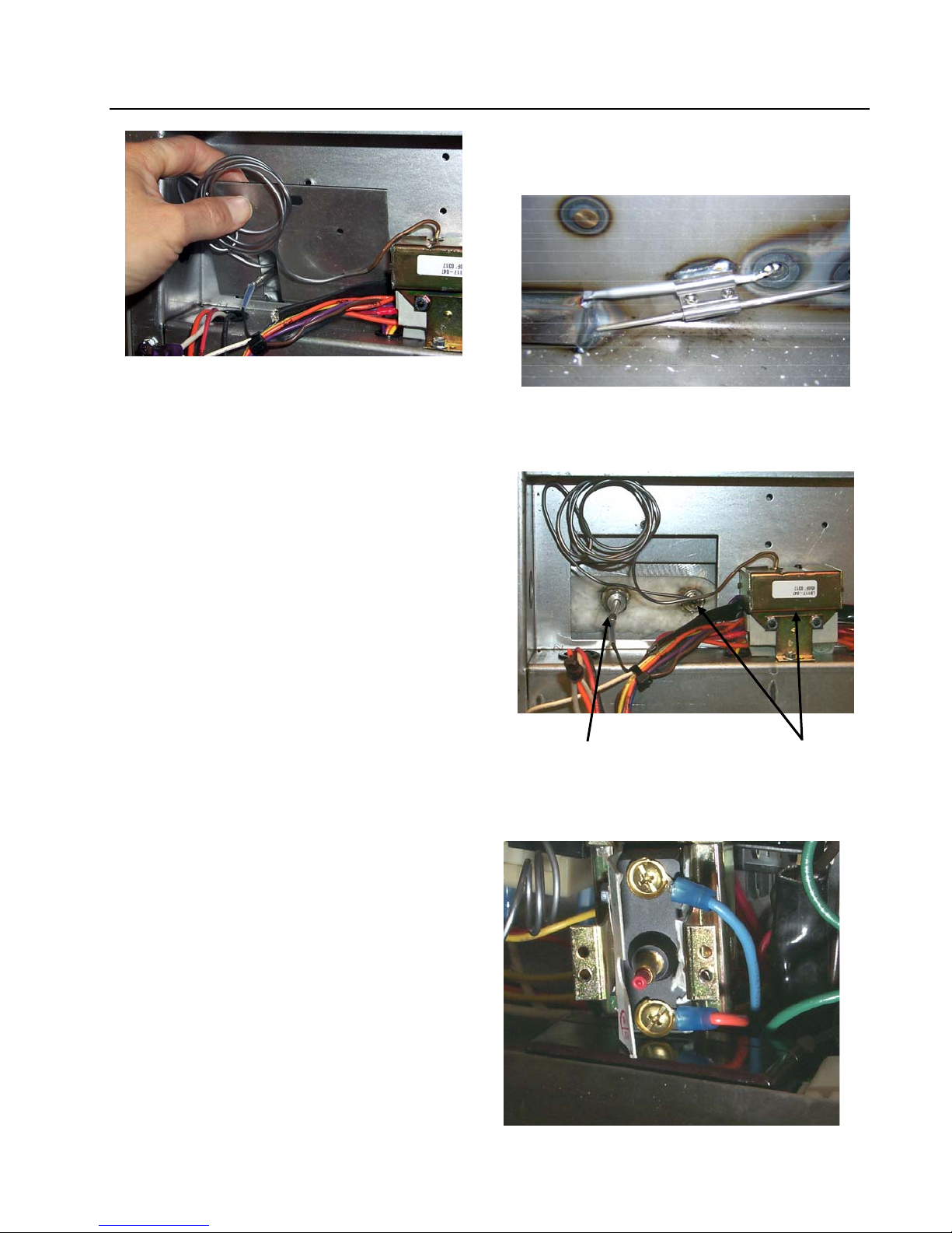
8. Remove the sensor bulb guard to access the
probe and high-limit (pictured above).
Current production systems have a sensor
bulb clamp that must be removed prior to
removing the probe or high-limit from the
frypot (pictured top right).
9. On the sensor bulb being removed, loosen
and unscrew completely the compression
nut, then the pass-through nut from the
frypot. Carefully remove the sensor bulb
from the frypot, being careful not to damage
the remaining sensor bulb.
Temperature probe. High-limit.
10. If removing the high-limit, remove the
screws securing it to the wireway box.
Mark and remove the wiring from the highlimit housing.
High-limit.
1-7
YSCFC SERIES FLATBOTTOM GAS FRYERS
CHAPTER 1: SERVICE PROCEDURES
11. Reverse steps to install new temperature probe or high-limit. If reinstalling high-limit, ensure the
capillary tube is properly routed around the temperature probe before tightening (see photo, Step
#8). Reconnect wiring removed from defective high-limit.
IMPORTANT (High-Limit): When installing new high-limit, ensure the capillary tube and
bulb are positioned properly with the mounting hardware installed prior to tightening the
compression nut. Once tightened, the capillary tube cannot be repositioned.
IMPORTANT (Temperature Probe):
When installing new temperature probe,
ensure probe is positioned properly with the
mounting hardware installed (current
production systems), or 1/8" from frypot
bottom (older systems), prior
to tightening
the compression nut. Once tightened, the
In older fryers, ensure probe tip is 1/8" from
frypot bottom for proper temperature sensing.
Frypot Bottom
probe cannot be repositioned.
1.6.2 Removing/Replacing Rocker Switches
1. Disconnect the fryer from the electrical supply.
2. The switches are located on a control box inside the unit. Remove the screws securing the front
panel of the control box. Do not allow the panel to hang by the switch wiring harness wiring;
use some type of support.
3. Depress the retaining clips (see illustration below) and push the switch out of the slot. If there is
a switch-guard present, retain it for installation of the replacement switch.
4. Remove wires one at a time from the switch being removed and connect to the replacement
switch until all wires are transferred.
When connecting wires to replacement
switch, pass the wires through the
switch guard (if applicable) before
connecting to switch.
Depress clips on each
end to remove switch
from control panel.
1-8
YSCFC SERIES FLATBOTTOM GAS FRYERS
CHAPTER 1: SERVICE PROCEDURES
5. Reverse the above steps for reassembly.
1.6.3 Replacing the Gas Valve
DANGER
Drain the frypot or remove drain valve handle to prevent accidental opening before
proceeding further.
1. Disconnect fryer from electrical and gas supplies.
2. Disconnect the wires from the gas valve terminal block, marking each wire to facilitate
reconnections.
3. Remove the high-limit thermostat wire from the gas valve coil (CE only).
4. Remove gas lines and pipe union collars from the gas valve and remove the valve.
5. Remove the pipefitting from the old gas valve and install on the replacement valve, using
Loctite PST567 or equivalent pipe thread sealant on threads. Do not apply sealant to the
first two pipe threads. Doing so will clog and damage the gas valve.
6. Reverse steps 1-5 to install the replacement gas valve.
1.6.4 Replacing Direct-Spark Ignitor Assembly (Units with Electronic Ignition Only)
1. Remove the burner shield from the
burner-box slots.
2. Disconnect sense wire and ignition
cable from the ignitor.
3. Remove the mounting screw from the
ignitor mounting-bracket and remove
the ignitor.
4. Reverse the procedure to replace the
ignitor assembly. Ensure the ignitor
is properly positioned in relation to
the center burner before tightening
mounting screw.
NOTE: The above procedure is
applicable to fryers equipped
Ensure ignitor is properly positioned (arrow) over
the center burner prior to tightening the mounting
screw.
with electronic ignition systems
only.
1-9
p
YSCFC SERIES FLATBOTTOM GAS FRYERS
CHAPTER 1: SERVICE PROCEDURES
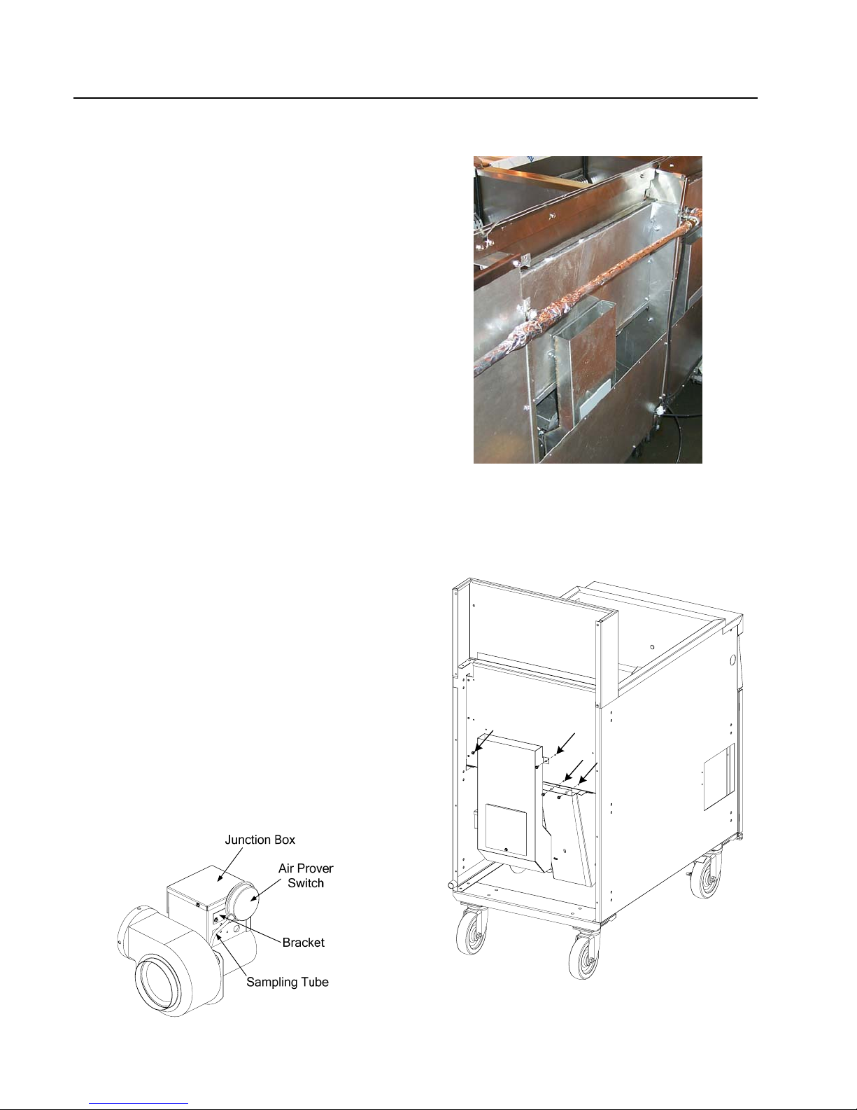
1.6.5 Removing/Replacing Blower Assembly or Air Prover Switch
1. Remove back panel. On systems with builtin filtration, use care not to damage the oilreturn heat-tape wiring insulation when
removing backs (multi-batteried systems after
02/03 have two-piece back panels; remove
both to access blower assembly).
2. Remove blower assembly by removing four
screws (two screws securing the flue outlet to
the firebox, and two screws securing the
blower inlet housing to the firebox). Pull the
assembly out of the slot and lower to the side.
Do not remove the electrical connections at
this time.
3. Remove junction box cover and mark and
disconnect wiring to the switch. Unscrew
fitting connecting sampling tube to air prover
switch, being careful not to kink the tube.
Remove two screws from bracket that
attaches switch to junction box to remove
switch. Install new air prover switch with
bracket. Reattach sampling tube and wires
Multi-batteried systems after have upper and lower
back panels, which must be removed to access the
blower assembly. (fryer at left shown with upper
back
anel removed).
removed from old switch and replace
junction box cover.
4. If replacing blower, remove junction box
cover, mark and disconnect each wire, and
remove conduit fitting from junction box.
Reinstall conduit fitting on new blower
and reconnect wiring. Replace box cover.
5. Reverse steps 1 – 2 to reinstall blower
assembly.
After removing screws (arrows), remove blower
assembly from firebox by pulling outward.
1-10

YSCFC SERIES FLATBOTTOM GAS FRYERS
CHAPTER 1: SERVICE PROCEDURES
1.6.6 Replacing the Frypot
Unit should be at room temperature, disconnected from gas and electrical service, and empty of oil
or shortening prior to beginning procedure.
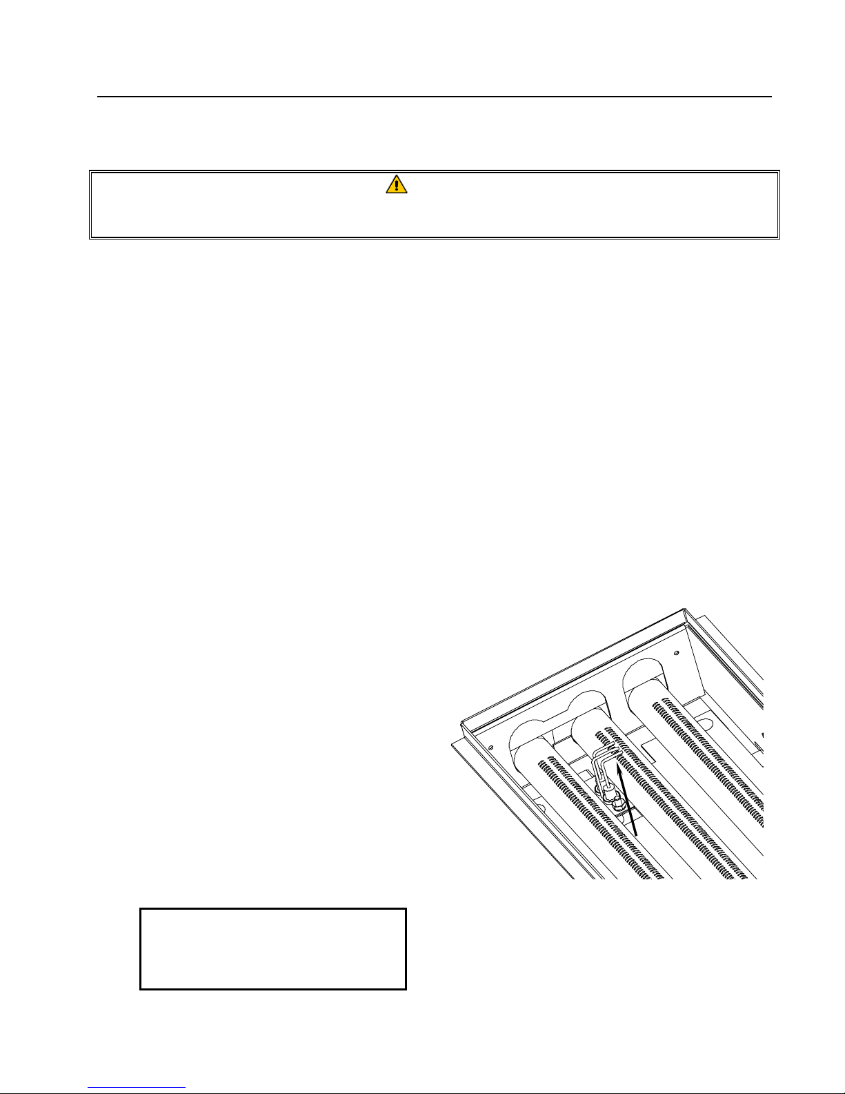
1.6.6.1 Frypot Baffle Inspection
1. Remove cabinet door(s) by holding door and lifting up on hinge pin. Current production model
doors have spring-loaded pins that must be disengaged from the control panel and the bottom
hinge. Remove marine edge (if applicable) by lifting up and off topcap and set aside.
2. The burner-tube retainer strip and burner tubes must be removed from the frypot/firebox being
inspected. Remove the burner-tube shield and the burner-tube retainer from the burner-box and
set aside. Lift the burner tubes up over each orifice and then pull outward to remove.
3. Disconnect the sense wire and ignition
cable and remove the direct-spark ignitor
assembly (with electronic ignition).
Inspect frypot baffles for signs of burnthrough or damage. If baffle burn-through
or damage is visible, proceed to the next
section. If not, and no further service to
frypot/firebox is required, reverse the
above steps to reassemble the fryer.
Inspect frypot baffles through burner tube opening
(arrow) for signs of burn-through or damage.
1-11

YSCFC SERIES FLATBOTTOM GAS FRYERS
CHAPTER 1: SERVICE PROCEDURES
1.6.6.2 Frypot/Firebox Removal/Replacement Procedure
1. Perform Procedure 1.6.5, Removing/Replacing Blower Assembly or Air Prover Switch, Steps 1 –
4.
2. Disconnect the union at the gas valve.
Remove four bolts connecting the burner
manifold brackets to the burner box.
Remove the burner manifold assembly
and set aside.
3. Mark and disconnect the drain-valve
microswitch wiring. Remove elbow or
drain-tee assembly, and then remove the
drain valve/microswitch assembly.
Disconnect
union at gas
valve and
remove four
bolts (two per
side) to
remove burner
manifold.
Remove drain
elbow and
drain valve
assembly from
the frypot.
Disconnect union at gas valve and remove four
bolts connecting burner manifold brackets to firebox
and drain valve assembly from frypot.
4. Remove two screws from control panel and lower, using care not to stretch or distort indicator
light wiring (if applicable). If control panel is equipped with indicator lights, mark and
disconnect wiring and set control panel aside.
If equipped with indicator lights, use a pin-pusher to remove pins from main-harness
connector, and then remove control panel.
5. Perform Procedure 1.6.1, Remove/Replace Temperature Probe or High-Limit Thermostat, Steps
7 – 11.
1-12

YSCFC SERIES FLATBOTTOM GAS FRYERS
CHAPTER 1: SERVICE PROCEDURES
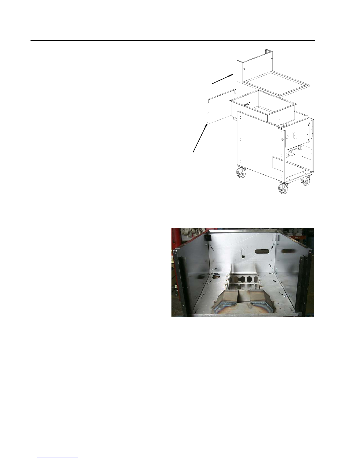
6. Remove two screws securing topcap to
wireway box. Remove topcap. Remove
four screws securing wireway box to fryer
cabinet (arrows) and carefully lower
wireway box out of the way. Use care not
to stretch or distort the wiring.
7. Remove two screws from the firebox heat
shield (arrows), remove heat shield and
set aside.
NOTE: Steps 8 and 9 must be performed
prior to frypot removal, especially on
systems with built-in filtration. Failure
to perform these steps will make frypot
removal extremely difficult, and cause
possible damage to firebox components
during removal.
8. Remove the burner box baffle by pushing
the baffle up into the burner box until the
baffle studs are clear of the slots. Tilt the
baffle at an angle and remove it from the
burner box.
9. Remove screws (two) securing the flame
spreader to the burner box. Allow the
spreader to drop down to clear the frypot
baffles.
Remove topcap, wireway box and front heat
shield to access firebox and frypot.
After removing burner-box baffle, remove screws
(two) securing the flame spreader to the burner
box. Allow the flame spreader to drop down in the
burner box to clear the frypot baffles. Repeat for
both sides.
1-13
YSCFC SERIES FLATBOTTOM GAS FRYERS
CHAPTER 1: SERVICE PROCEDURES
10. Remove firebox back, along with
insulation from back of frypot. From the
rear of the unit, use a prying bar to
carefully pry the top assembly from the
frypot and cabinet frame (single units
only), and set aside. (The top assembly is
secured to the frypot with high-temp
silicone sealant.) On systems, remove
individual pieces on the frypot being
removed.
11. Pull the frypot back and up to remove. On
fryers with built-in filtration systems,
ensure the front oil-return inlet is clear of
the firebox front before lifting frypot out
of cabinet.
If the Firebox Requires Replacement:
12. Remove screws (12) securing the firebox
to the cabinet braces (arrows). Lift the
firebox assembly back and up to remove
from cabinet.
Use a pry bar to
remove top
assembly from
frypot (single
units only).
Remove the
firebox back and
insulation from
back of frypot.
Remove screws (arrows) securing the firebox to
the cabinet.
1-14
YSCFC SERIES FLATBOTTOM GAS FRYERS
CHAPTER 1: SERVICE PROCEDURES
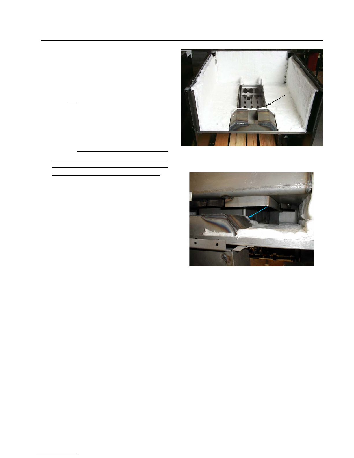
13. Install new firebox into cabinet. Replace
screws (12) removed during removal of
the old firebox. Use spray adhesive (Zep
Aero Tac High-Strength Spray Adhesive
or equivalent) to install new insulation in
firebox bottom as shown. The insulation
must not go above the top of the burnerbox center flange.
NOTE: Ensure the strip of insulation is
properly affixed to the front blowerhousing flange (arrow) prior to installing
frypot. Failure to install the insulation
strip will result in frypot-baffle burnout,
blower damage and fryer malfunction,
and will void all applicable warranties.
Install new insulation in firebox using spray
adhesive, ensuring good contact between
insulation and metal surfaces.
14. Install new frypot, using care not to
damage the firebox insulation. Ensure
the blower-housing insulation strip
remains in place after installing the new
frypot (arrow).
Reverse the above steps to reassemble the
fryer. Use high-temp silicone to re-install
the top assembly (single fryers) or joiner
strips, flue caps, etc. (systems).
Ensure blower-housing insulation strip remains in
place after installing the new frypot (arrow).
1.7 Troubleshooting and Problem Isolation
This section is intended to provide technicians with a general knowledge of the broad problem
categories associated with this equipment, and the probable causes of each. With this knowledge,
the technician should be able to isolate and correct any problem encountered.
Problems you are likely to encounter with YSCFC Series Flatbottom fryers can be grouped into five
categories:
1. Ignition failures
2. Improper burner functioning
4. Filtration problems
5. Leakage
3. Improper temperature control
1-15

YSCFC SERIES FLATBOTTOM GAS FRYERS
CHAPTER 1: SERVICE PROCEDURES
The probable causes of each category are discussed in the following sections. Troubleshooting
guides are included in Section 1.8 to assist in identifying some of the more common problems.
1.7.1 Ignition Failures
Ignition failure occurs when the ignition module fails to sense a flame within the 11-second time
delay period and locks out. Turn the fryer off, locate and correct the problem, then turn fryer back
on to clear the module lock.
There are three primary reasons for ignition failure, listed in order of probability:
1. Problems related to the gas and/or electrical power supplies.
2. Problems related to the electronic circuits.
3. Problems related to the gas valve.
Problems Related to the Gas and/or Electrical Power Supplies
The main indicator is that an entire battery of fryers fails to light. Verify that the quick disconnect
hose is properly connected, the fryer is connected to power, the main gas supply valve is open, and
the circuit breaker for the fryer electrical supply is not tripped. Some fryers are equipped with a
fryer reset-switch that must be reset each time the fryer is turned off.
Problems Related to the Electronic Circuits
If gas and electrical power are supplied to the fryer, the next most likely cause of ignition failure is a
problem in the 24 VAC circuit of electronic ignition systems. If the fryer is equipped with a
filtration system, first verify that the drain valve is fully closed. (The valve is equipped with a
microswitch that must be closed for power to reach the gas valve. Often, although the valve handle
appears to be in the closed position, the microswitch is still open.) If the valve is fully closed, or the
fryer does not have a filtration system, refer to the troubleshooting guides in this chapter.
Problems Related to the Gas Valve
If the problem is not in the 24 VAC circuit, it is most likely in the gas valve itself, but before
replacing the gas valve, refer to the troubleshooting guides in this chapter.
1-16

YSCFC SERIES FLATBOTTOM GAS FRYERS
CHAPTER 1: SERVICE PROCEDURES
1.7.2 Improper Burner Functioning
With problems in this category, the burner ignites but exhibits abnormal characteristics such as
"popping", incomplete lighting of burner, fluctuating flame intensity, and flames "rolling" out of the
fryer.
"Popping" indicates delayed ignition. In this condition, the main gas valve is opening but the burner
is not immediately lighting. When ignition does take place, the excess gas "explodes" into flame,
rather than smoothly igniting.
The primary causes of popping are:
• Incorrect or fluctuating gas pressure
• Clogged burner orifices
• Clogged burners
• Inadequate make-up air
• Heat damage to the controller or ignition module
• An out-of-adjustment ignitor or broken ignition wire
• A defective ignition module
If popping occurs only during peak operating hours, the problem may be incorrect or fluctuating gas
pressure. Verify that the incoming gas pressure (pressure to the gas valve) is in accordance with the
appropriate CE or Non-CE requirements listed in the Installation and Operation manual that came
with the fryer, and that the pressure remains constant throughout all hours of usage. Refer to
Adjusting Burner Manifold Pressure in Section 1.4 if burner manifold pressure is suspected of
being incorrect.
On systems equipped with electronic ignition, verify that the ignitor is properly adjusted (electrode
tip and ignitor positioned properly over middle burner).
Clogged burners and burner orifices are also likely causes of delayed ignition. Clogged burners are
indicated by uneven flame or partial flame on the burner face. Clogged orifices are indicated by no
flame.
Another cause of popping is an insufficient air supply or drafts. Check for "negative pressure"
conditions in the kitchen area. If air is flowing into the kitchen area, more air is being exhausted
than is being replenished and the burners may be starved for air.
If the fryer’s gas and air supplies are okay, the problem most likely is with one of the electrical
components. Examine the ignition module for signs of melting/distortion and/or discoloration due to
excessive heat build-up in the fryer. (This condition usually indicates improper flue performance.).
1-17

YSCFC SERIES FLATBOTTOM GAS FRYERS
CHAPTER 1: SERVICE PROCEDURES
Also, examine the controller for the same conditions. A melted or distorted ignition module is
automatically suspect and should be replaced, but unless the condition causing excessive heat in the
fryer is corrected, the problem is likely to recur.
Next, ensure the ignition wire is connected properly at both ends and examine it for obvious signs of
damage. Again, if damage is due to excessive heat in the fryer, that problem must also be corrected.
DANGER
MAKE SURE YOU ARE HOLDING THE INSULATED HANDLE OF THE SCREWDRIVER
AND NOT THE BLADE. THE SPARKING CHARGE IS APPROXIMATELY 25,000
VOLTS.
Check for proper operation by disconnecting the wire from the ignitor, inserting the tip of a
screwdriver into the terminal, and holding it near the frame of the fryer as the power switch is placed
in the "ON" position. A strong, blue spark should be generated for at least 11 seconds.
Fluctuating flame intensity is normally caused by either improper or fluctuating incoming gas
pressure, but may also be the result of variations in the kitchen atmosphere. Verify incoming gas
pressure in the same way as for "popping", discussed in the preceding paragraphs. Variations in the
kitchen atmosphere are usually caused by air conditioning and/or ventilation systems starting and
stopping during the day. As air conditioning/ventilation systems start and stop, the pressure in the
kitchen may change from positive or neutral to negative, or vice versa. Changes in airflow patterns
may affect flame intensity.
Flames "rolling" out of the fryer are usually an indication of negative pressure in the kitchen. Air is
being sucked out of the fryer enclosure and the flames are literally following the air. If negative
pressure is not the cause, check for high burner-manifold gas pressure in accordance with the
procedures in Section 1.4. An obstructed flue or a faulty blower, which prevents the fryer from
properly exhausting, may also be the cause.
Excessively noisy burners, especially with flames visible above the flue opening, may indicate that
the burner gas pressure is too high or the gas valve vent-tube is blocked (if applicable). If the gas
pressure is correct, and the vent-tube is unobstructed (if applicable), the gas valve regulator is
probably defective.
1-18

YSCFC SERIES FLATBOTTOM GAS FRYERS
CHAPTER 1: SERVICE PROCEDURES
1.7.3 Improper Temperature Control
Temperature control, including the melt cycle, is a function of several interrelated components, each
of which must operate correctly. The principal component is the temperature probe. Depending
upon the specific configuration of the fryer, other components may include the Thermatron board,
the controller itself, and the ignition module.
Improper temperature control problems can be categorized into melt cycle problems and failure to
control at setpoint.
Failure to Control at Setpoint
In fryers equipped with a Thermatron temperature controller, the problem may be that the
temperature probe is improperly positioned. Other causes may be the Thermatron board or the
potentiometer. Possible causes are that the potentiometer is out of calibration, or the temperature
probe or Thermatron board is defective. Refer to Section 1.5 for instructions on calibrating the
Thermatron temperature controller.
1.7.4 Filtration Problems
Whenever the complaint is "the pump is running, but no oil is being filtered", check the filter paper
or filter leaf (screen) connections and ensure they are properly connected. Ensure the filter paper or
filter leaf is not clogged with food debris or sediment and is properly assembled.
If the pump motor overheats, a circuit breaker in the filter circuit will trip and the motor will not start
until it is reset. If the pump motor does not start after pressing the circuit breaker, press the red reset
switch located on the rear of the motor. If the pump then starts, something caused the motor to
overheat. Maybe several frypots were filtered one after the other and the pump got hot. Letting the
motor cool down for at least a half-hour is all that is required in this case. More often, the pump
overheated for one of the following reasons:
• Shortening was solidified in the filter leaf or filter lines.
• The operator attempted to filter unheated oil or shortening. Cold oil and shortening are thicker
and cause the pump motor to work harder and overheat.
If the motor runs but the pump does not, there is a blockage in the pump. An incorrectly assembled
filter leaf allows food particles and sediment to pass through the filter pan and into the pump. When
sediment enters the pump, the gears bind up causing the motor to overheat, tripping the thermal
overload. Particles large enough to clog the pump may indicate that the crumb tray is not being used,
and that the filter leaf is not properly assembled. Solidified shortening in the pump will produce the
same result.
1-19

YSCFC SERIES FLATBOTTOM GAS FRYERS
CHAPTER 1: SERVICE PROCEDURES
A pump seized by debris or hard shortening must be disassembled, cleaned and reassembled as
follows:
1. Disconnect power to the filter system.
2. Remove the front cover of the pump to access the gears inside, if the pump is accessible while
still inside the cabinet. If the front cover is not accessible, the pump must be removed from the
pump motor (remove input/output plumbing from the pump prior to removing pump). Remove
setscrews to disengage the pump from the motor.
3. Prior to reassembly, the inside housing must be clean and free of any sediment or debris. Failure
to completely clean the inside housing and ring gear will cause gear binding after reassembly.
4. During reassembly, partially install the housing bolts in a star pattern, leaving a ⅛-inch (3 mm)
gap between the cover and housing flanges. Ensure there is no shortening or oil in the filter pan,
and that the filter pan is disconnected. With the motor running slowly draw the cover in, evenly
tightening the housing bolts. When the cover is snug on the housing tighten all bolts to 15 inchlbs (1.7 Nm) ensuring that the pump is working correctly. Turn the motor off.
The electronics of the SUFF/UFF filtration system are simple and straightforward. Microswitches
attached to handles for each vat and wired in parallel provide the 24 VAC required to activate the
pump relay coil. When the handles are moved to the ON position, the activated pump relay coil pulls
the pump motor switch in, supplying power to the pump motor.
Filter systems equipped with oil-return heaters are wired into the 120 VAC source, which remains
energized as long as the unit is plugged in.
1-20

YSCFC SERIES FLATBOTTOM GAS FRYERS
CHAPTER 1: SERVICE PROCEDURES
1.7.5 Leakage
Frypot leaks are usually due to improperly sealed high-limit, temperature probe or oil-return and
drain fittings. When installed or replaced, each of these components must be sealed with Loctite
PST567 sealant or equivalent to prevent leakage. In very rare cases, a leak may develop along one
of the welded corners of the frypot. When this occurs, the frypot must be repaired or replaced.
Frypot locations (indicated by arrows) where potential leaks could occur.
1-21

YSCFC SERIES FLATBOTTOM GAS FRYERS
CHAPTER 1: SERVICE PROCEDURES
1.8 Troubleshooting Guides
The following procedures must be performed by an ASA. They are provided as an aid to expedite
troubleshooting and repair of YSCFC Series frying systems.
1.8.1 Main Burner Malfunctions
PROBLEM CORRECTIVE ACTION
Main burner will not
come on even though
air blower is in
operation; no gas
pressure at main
burner.
Air blower is not
operating, although
power is present at the
fryer.
Main burner flames are
small and appear lazy;
Oil does not come up
to temperature quickly.
1. Check that the combination gas valve is ON.
2. Check high temperature safety switch. Replace if defective.
3. Check air prover switch. Ensure green prover light is on. If not,
check for 24 VAC going into and coming out of the air prover
switch.
1. Cooked product or other material may have fallen into the flue
and lodged in the blower wheel, preventing it from turning.
Clean out flue and blower wheel.
2. Blower motor may have overheated and shut off. This
condition will correct itself when motor cools (20 minutes). If
problems with blower overheating persist, call for service.
3. If fryer is equipped with a Thermatron controller, the
temperature probe or the controller board may be defective.
1. Check gas pressure at the pressure tap of the burner manifold.
Use a standard water-type U-gauge manometer. With the
burner in operation, the pressure should be about 4" W.C. on
natural and 11" W.C. on propane (LP) gases. If not, unscrew
the cover of the pressure regulator adjustment and turn the
adjusting screw clockwise to increase gas pressure (or
counterclockwise to decrease the pressure). Replace cover
and plug.
There are signs of
excessive frypot
temperature;
oil becomes
discolored quickly.
1. Check the frypot for excessive build up of debris.
2. Thermatron controller may be out of calibration. Re-calibrate
in accordance with instructions in Section 1.5.
3. Check gas pressure.
4. Oil of inferior quality or used too long. Replace with quality oil.
1-22

YSCFC SERIES FLATBOTTOM GAS FRYERS
CHAPTER 1: SERVICE PROCEDURES
1.8.2 Indicator Lights
The fryer’s indicator lights serve a diagnostic purpose. All lights are lit when the fryer is working
properly. The green light on the control panel will cycle on and off as the fryer calls for heat. Use
the following procedures to isolate problems indicated by light combinations.
Turn the temperature dial to 400°F (204°C) to ensure the sensor will demand heat. Check all
indicator lights in the fryer cabinet and on the control panel. [Older units may have power and reset
switches with different colored lights (orange, amber, red, green, white.). Common Cabinet units
have a white power light and a green air prover light. Substitute the light color of the correct color
switch with the respective "green light" switch in the following troubleshooting procedures. The
control panel light colors haven’t changed.]
When turning the power switch "ON" and resetting the safety (reset) switch, check for the following:
LIGHT INDICATION PROBABLE CAUSE CORRECTIVE ACTION
GREEN LIGHT/POWER SWITCH IS
"ON"
GREEN LIGHT/SAFETY (RESET)
SWITCH IS "OFF"
GREEN LIGHT/CONTROL PANEL IS
"OFF"
RED LIGHT/CONTROL PANEL IS
"OFF"
1. The drain valve is open.
2. The drain switch is defective.
1. Ensure the drain valve is
completely closed, and then
turn the reset switch to "ON".
GREEN LIGHT/POWER SWITCH IS
"OFF"
GREEN LIGHT/SAFETY (RESET)
SWITCH IS "OFF"
GREEN LIGHT/ CONTROL PANEL IS
"OFF"
RED LIGHT/CONTROL PANEL IS
"OFF"
1. No power to fryer.
2. Fuse is blown.
3. Reset switch circuit defective.
1. Check power source, power
cords and breaker. Ensure that
electricity is available to the
fryer.
2. Replace fuse.
3. If fryer does not function after
resetting the reset switch,
contact an ASA for assistance.
1-23
YSCFC SERIES FLATBOTTOM GAS FRYERS
CHAPTER 1: SERVICE PROCEDURES
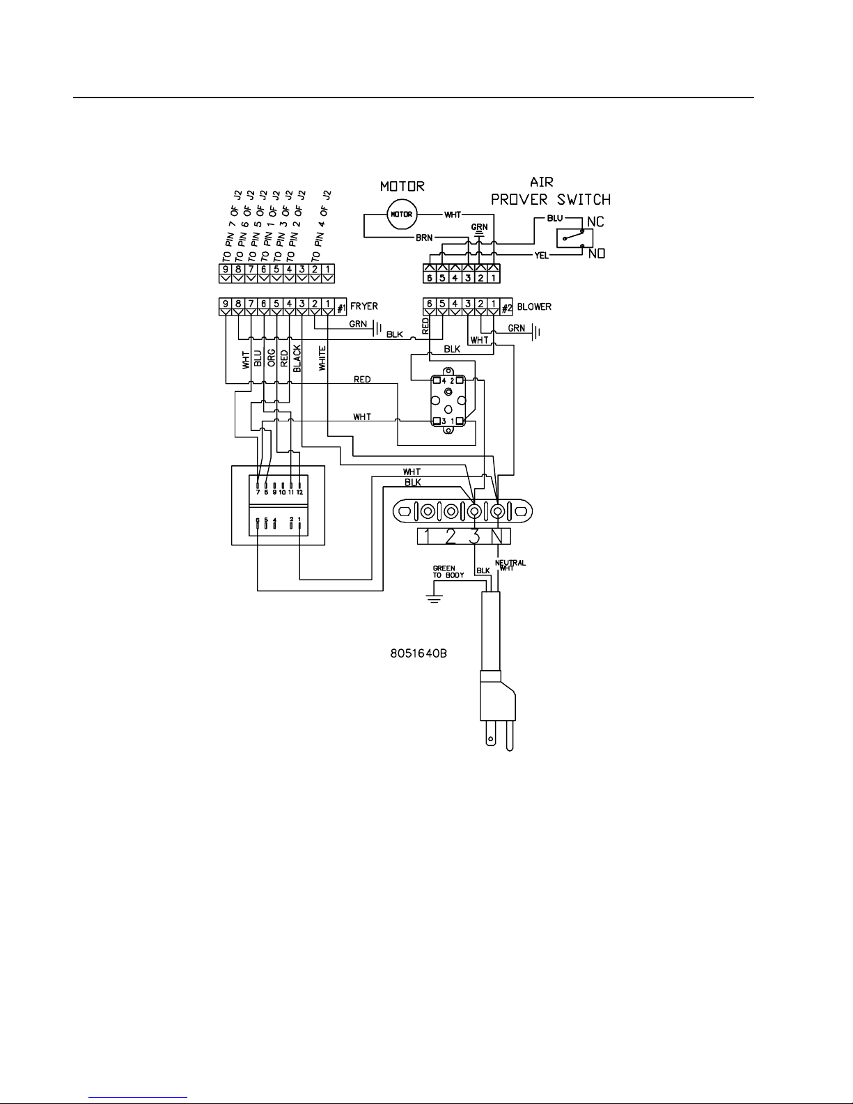
1.9 WIRING DIAGRAMS
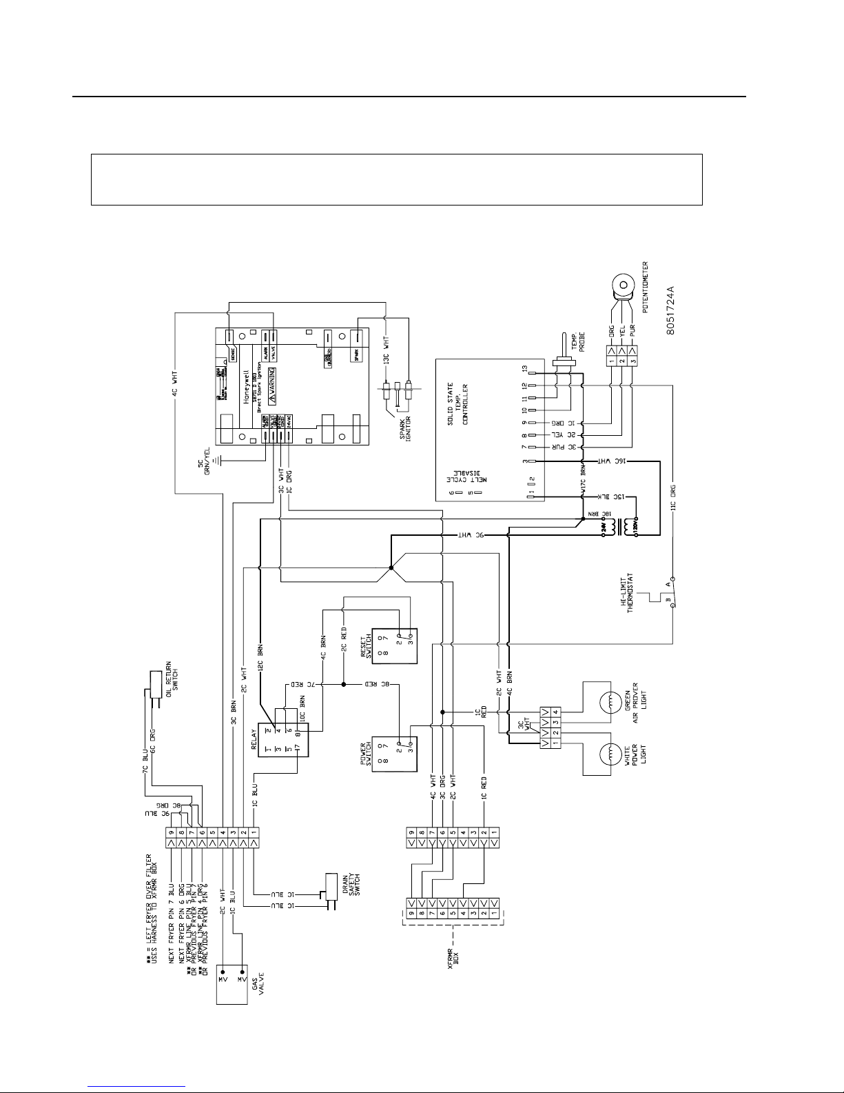
NOTE: The diagrams in this section depict wiring as of the date of manual publication. It
may not reflect design changes made to the equipment after publication. Always refer to
the wiring diagram affixed to the unit when actually troubleshooting this equipment.
1.9.1 Wiring for Common Cabinet Flatbottom without Boil Out
1-24

YSCFC SERIES FLATBOTTOM GAS FRYERS
1.9.2 24/24 Filter Wiring
CHAPTER 1: SERVICE PROCEDURES
1-25
YSCFC SERIES FLATBOTTOM GAS FRYERS
CHAPTER 1: SERVICE PROCEDURES
1.9.3 18/24 Common Cabinet Transformer Box
1-26

YSCFC SERIES FLATBOTTOM GAS FRYERS
CHAPTER 2: PARTS LIST
2.1 Blower Assembly and Combustion Air
4
5
1
2
3
ITEM PART # COMPONENT
1 108-0471SP Motor, Blower Assembly, 120V
2 823-3162 Duct Assembly, Inlet
3 200-1428 Gate, Air Flow
4 823-3166 Duct Assembly, Outlet
5 200-1471 Door, Outlet Duct Access
* Not illustrated.
2-1

YSCFC SERIES FLATBOTTOM GAS FRYERS
CHAPTER 2: PARTS LIST
2.2 Burner Manifold and Related Components
20
19
8
9
10
11
7
6
1
5
2
12
13
14
15
4
16
3
21
17
18
2-2

YSCFC SERIES FLATBOTTOM GAS FRYERS
CHAPTER 2: PARTS LIST
2.2 Burner Manifold and Related Components (cont.)
ITEM PART # COMPONENT
1 810-2129 Tube, Burner
2 200-1670 Support, Left or Right Manifold
3 810-2168 Burner Manifold Assembly
4
810-2827 2.82mm (#34) Natural Gas
810-2830 1.78mm (#50) Propane (LP) Gas
5 813-0154 Plug, ⅛" NPT (Manifold Pressure Tap Plug)
6 813-0174 Union, ¾" NPT Pipe
7 813-0300 Nipple, ¾" NPT x 4½"
8 813-0066 Elbow, 90° x ¾" NPT
9 813-0112 Nipple, ¾" NPT x 2"
10 813-0168 Elbow, 90° x ¾" NPT Street
11
807-3555 24V Natural (G20/G25) Honeywell
807-3690 24V Propane (LP) (G31) Honeywell
* 106-6553 Vent Tube
12 813-0763 Bushing, ¾" NPT to ½" NPT
13 813-0022 Nipple, ½" NPT x Close
14 813-0173 Union, ½" NPT Pipe
15 813-0165 Elbow, 90° x ½" NPT Street (for single fryers, use 45° 813-0342)
16 813-0265 Nipple, ½" NPT x 2½"
17 813-0062 Elbow, 90° x ½" NPT
18 813-0845 Nipple, ½" NPT x 29¾" (single fryers, use 24½" 813-0788, 813-0729 23”)
* 813-0608 Coupling, ½" NPT
* 813-0475 Tee, 1" x ½" x ¾"
* 813-0460 Nipple, ½" x 3" NPT
* 813-0421 Nipple, 1" x 18" NPT
* 813-0418 Nipple, ½" x 17" NPT
* 813-0275 Nipple, ½" x 9" NPT
* 813-0266 Elbow, Street, 1" NPT
* 813-0247 Nipple, ½" x 3.5" NPT
* 813-0087 Nipple, ½" x 1.5" NPT
* 813-0031 Bushing, Hex, ¾" NPT x ½"
* 810-2898 Clamp, Pipe, 1"
19 807-3556 Ignitor and Flame Sensor Assembly (does not include flame sensor wire or cable)
* 106-4580 Ignitor Bracket, Flat Style
20 106-3338 Ignition Cable (includes 807-3742 cable and 807-3484 Rajah connector)
21 807-3365 Module, Ignition Spark, Honeywell
* W106C6SP Sensor Cable
*Not illustrated.
Orifice
Valve, Gas
Electronic Ignition Components
2-3
YSCFC SERIES FLATBOTTOM GAS FRYERS
CHAPTER 2: PARTS LIST
2.3 Flue Caps, Top Caps, and Related Components
4
9
8
10
3
6
7
2
12
1
5
2-4
11

YSCFC SERIES FLATBOTTOM GAS FRYERS
CHAPTER 2: PARTS LIST
2.3 Flue Caps, Top Caps, and Related Components (cont.)
ITEM PART # COMPONENT
1 106-3253SP Frame, Single Crumb Dump
2 106-1638SP Frame, Double Crumb Dump
3 823-4125 Insert, Pan Crumb Dump, ½ Size
4 823-4127 Tray, 12424 Single
5 106-2840SP Cover, 1824G Frypot (use 106-2839SP for 2424G Frypot)
6
230-1387 For use on 2-2424G (2-vat 2424 System)
230-1390 For use on 3-2424G (3-vat 2424 System)
230-1385 For use on 2-1824G (2-vat 1824 System)
230-2996 For use on 2-2424/15R (3-vat 24/15 System)
7
230-0778 For use on 2-2424G (2-vat 2424 System)
230-1589 For use on 2-1824G (2-vat 1824 System)
230-2966 For use on 2-2424/15R (3-vat 24/15 System)
230-0396 For use on 3-2424G (3-vat 2424 System)
8 210-4317 Edge Strip, Frypot
9 210-4313 Joiner Strip (joins frypots within a system)
10 210-4598 Joiner Strip (joins one fryer system to another)
* 230-3089 Joiner Strip (joins matching cabinet to fryer)
11
823-5640 2-vat 2424, Without Notches
823-5816 2-vat 2424, Notched Right End
823-5817 2-vat 2424, Notched Left End
823-5829 2-vat 1824, Notched Left End
823-5514 3-vat 2424, Without Notches
823-5872 3-vat 2424, Notched Right End
12
106-5875 224
106-8395 324
106-6504 1824
106-7947 24/24/MC15
* 803-0293 Gloves, Neoprene Hot Oil
* Not illustrated.
Deflector, Flue Cap Oil
Flue Cap
Marine Edge
Frame, Control Panel
2-5

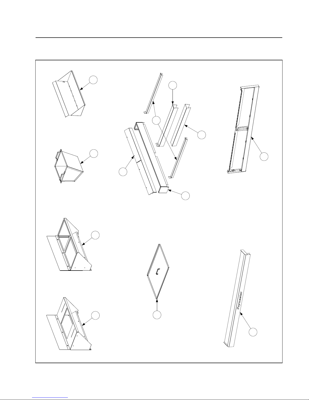
2.4 Cabinetry
YSCFC SERIES FLATBOTTOM GAS FRYERS
CHAPTER 2: PARTS LIST
2-6

YSCFC SERIES FLATBOTTOM GAS FRYERS
CHAPTER 2: PARTS LIST
2.4 Cabinetry (cont.)
ITEM PART # COMPONENT
1 220-0366 Back, Upper Cabinet, 2424
220-0862 Back, Upper Cabinet, 1824
220-2938 Back, Upper Cabinet, MC15
2 220-0365 Back, Lower Cabinet, 2424
220-0863 Back, Lower Cabinet, 1824
220-2939 Back, Lower Cabinet, MC15
3 231-0395 Panel, Left Side, Stainless Steel Cabinet
* 232-0395 Panel, Right Side, Stainless Steel Cabinet
* 221-0853 Panel, Left Side, Stainless Steel Cabinet with Cut-out
4 222-0853 Panel, Right Side, Stainless Steel Cabinet with Cut-out
5 200-1471 Door, Access Duct
6 220-0762 Brace, Firebox
7 220-0761 Brace, Frypot
8 220-0369 Post, Front Cabinet
9 220-0404 Post, Rear Cabinet
10 810-0357 Caster, 5" with Brake Swivel (4-hole pattern)
* 810-0356 Caster, 5" without Brake Swivel (4-hole patter)
11 220-3537 Bridge, Filter Pump
12 220-3790 Support, Filter Pump Motor
13 221-0980 Guide, Filter Pan, Left
14 222-0980 Guide, Filter Pan, Right
15 221-4734 Rail, Filter Pan, Left
16 222-4734 Rail, Filter Pan, Right
17 220-4149 Stop, Drain Pan, 2424
* 220-4891 Stop, Drain Pan, MC15
18 220-0760 Divider, Frypot
19 200-9231 Brace, Cabinet Front, 224
220-3793 Brace, Cabinet Front, 324
220-3501 Brace, Cabinet Front, 324, Filter on Right (facing the fryer)
200-9240 Brace, Cabinet Front, 1824
220-2970 Brace, Cabinet Front, 24/24/15
20 200-9229 Brace, Cabinet Top, 224
200-3793 Brace, Cabinet Top, 324
200-9239 Brace, Cabinet Top, 1824
220-2943 Brace, Cabinet Top, 24/24/15
21
810-3088 224
810-3313 324, Filter on Left (facing the fryer)
810-3314 324, Filter on Right (facing the fryer)
810-3093 18/24
810-3239 24/24/15
*
106-5788 224
106-8393 324, Filter on Left (facing the fryer)
106-8394 324, Filter on Right (facing the fryer)
106-6502 18/24
106-7948 24/24/15
* Not illustrated.
Oil Return Manifold
Cabinet Base
2-7
YSCFC SERIES FLATBOTTOM GAS FRYERS
CHAPTER 2: PARTS LIST
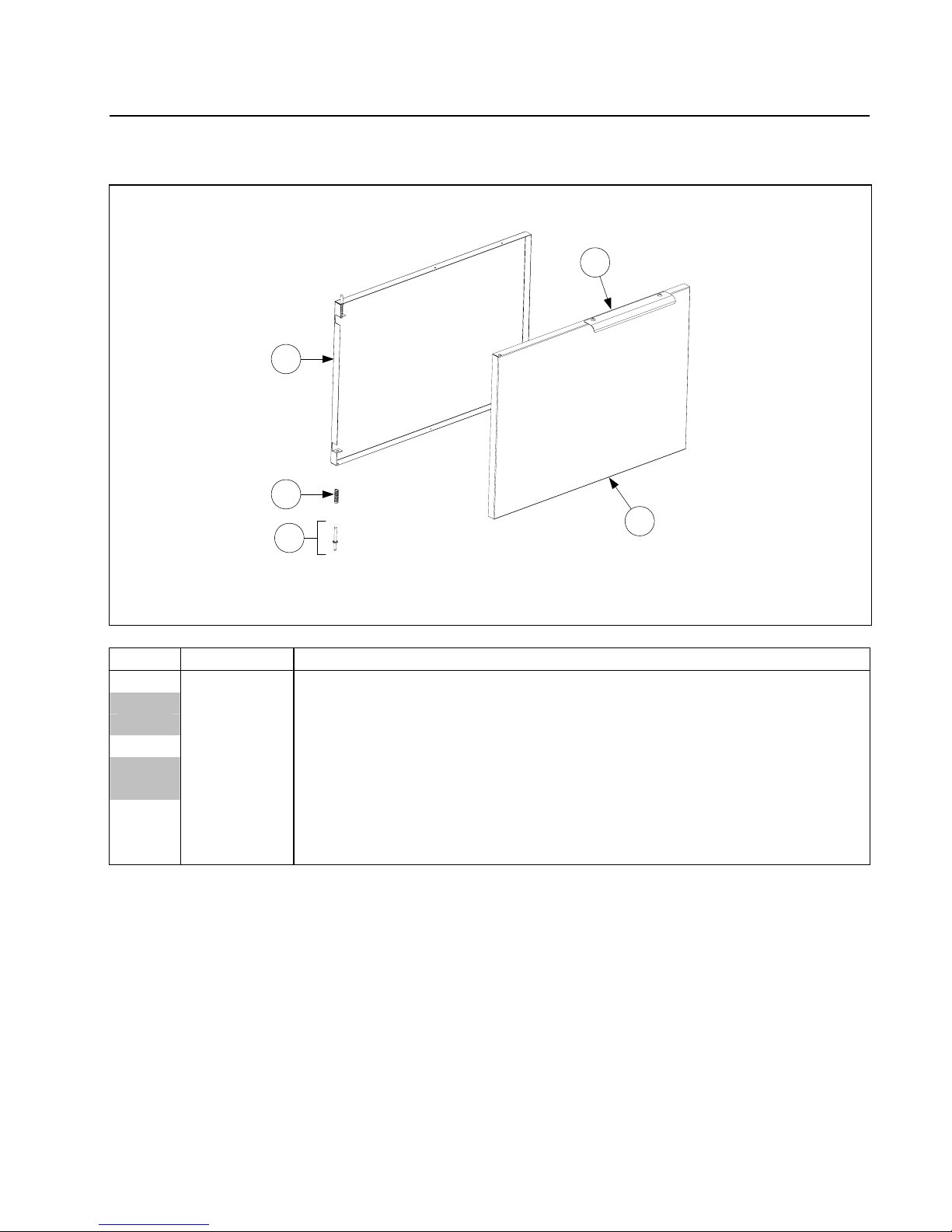
2.5 Door Assemblies and Component Parts
2
5
4
1
3
ITEM PART # COMPONENT
1 824-1912 Panel, Door, 2424
824-1958 Panel, Door, 1824
824-1954 Panel, Door, MC15
2 220-4128 Liner, Door, 2424
220-4742 Liner, Door, 1824
220-4666 Liner, Door, MC15
3 106-4067 Pin Assembly
4 810-0275 Spring
5 210-8077 Handle
2-8

YSCFC SERIES FLATBOTTOM GAS FRYERS
CHAPTER 2: PARTS LIST
2.6 Control Panels, Wireways, and Related Components
2-9

YSCFC SERIES FLATBOTTOM GAS FRYERS
CHAPTER 2: PARTS LIST
2.6 Control Panels, Wireways, and Related Components (cont.)
ITEM PART # COMPONENT
1 106-6060 Plate, Microswitch Adjustment
2 807-4114 Relay, Latch/Filter 24VAC Coil
3 200-4719 Plate, Interface Board Mounting
4 200-9681 Support, High Limit Thermostat
5 200-9812 Plate, Component Box Cover
6 220-1283 Box, Component Harness
7 220-1284 Housing, Thermostat
8 220-3769 Bracket, Relay
9 230-1282 Plate, Thermatron Face
10 807-0800 Transformer, 120V 50/60 Hz – 24V, 50 VA
11 807-2103 Microswitch, Straight Lever
12 807-2469 Bushing, Heyco, 1" ID
13 807-3365 Ignition Module, Honeywell
14 826-2086 Thermatron Board, 115/230V, Extended Melt Cycle
15 807-3574 Switch, Dean Power
16 807-3575 Switch, Hole Plug
17 807-3576 Switch, Reset-Rocker
18 807-3680 Thermostat, 450°F High-Limit w/Manual Reset
19 810-0110 Knob, Thermatron Control
20 826-2269 Potentiometer, Thermatron
21 106-2607 Probe, Thermatron (20" leads)
22 816-0220 Insulation, Switch
23 823-5765 Component Box
24 802-2050 Label, Three-Switch
25 802-2052 Label, Thermatron Dial
26 200-4719 Harness, Thermostat
2-10

YSCFC SERIES FLATBOTTOM GAS FRYERS
CHAPTER 2: PARTS LIST
2.7 Oil Return and Suction Manifolds
8
3
11
6
10
9
4
2
To port on
Section 2.9
frypot front; see
7
12
5
5
13
Section 2.8
To filter unit; see
15
16
17
14
18
1
28
19
20
21
24
23
22
26
25
27
7
tube; see Section 2.9
To flush on end of drain
29
30
31
32
5
33
2-11

YSCFC SERIES FLATBOTTOM GAS FRYERS
CHAPTER 2: PARTS LIST
2.7 Oil Return and Suction Manifolds (cont.)
ITEM PART # COMPONENT
1 810-3088
106-5461
Oil Return Manifold
Oil Return Plumbing
2 810-2125 Drain Valve, ⅜" Ball Valve
3 810-3011 Tubing, Drain Valve, Front
4 810-3014 Tubing, Oil Return, Rear
5 813-0165 Elbow, Street, ½" x ½" NPT, 90°
6 813-0462 Coupling, ⅜"
7 813-0613 Flare Fitting, ½-37° x ½"
8 813-0614 Flare Fitting, ½-37° x ⅜"
9 813-0631 Elbow, ⅜" x 90°
10 813-0649 Nipple, Black Tube, ⅜" NPT x 2.5"
11 813-0894 Elbow, ⅜" NPT x ½-37° Flare
12 823-5815 Oil Return Handle
Pump and Motor
13 810-3347 Pump, Viking 8 GPM
14 826-1712 Motor, 115V 60Hz (gasket included)
* 826-1270 Motor, 230V 50/60Hz (gasket included)
* 816-0093 Gasket, Pump/Motor (included with motor)
15 813-0168 Elbow, ¾" x ¾" NPT, Street, 90°
16 813-0031 Bushing, Hex, ¾" NPT x ½"
17 810-1668 Adapter, Male, ⅝" OD x ½"
18 810-1067 Flexline, ⅝" OD x 8.5" long
19 813-0298 Nipple, ½" x 2.0" NPT
20 813-0062 Elbow, ½", 90°
21 813-0304 Bushing, ½" x ¼", Flush
22 813-0838 Nipple, ¼" NPT, Close
23 810-1669 Adapter, Female, ⅞" OD x ½"
24 810-1339 Flexline, ⅝" OD x 4.5" long
25 813-0003 Tee, ½" x ½" x ½"
26 813-0022 Nipple, ½" x Close NPT
27 810-1055 Flexline, ⅝" OD x 11.5" long
28 106-3470SP Valve, Solenoid, Female Pins
* 813-0265 Nipple, ½" x 2.5" NPT
* 807-2304 Heater Strip, 72", 120V/100W, Silicone
* 806-8004SP Heater Strip, 56", 120V/40W, Silicone
* 807-1105 Heater Strip, 18", 120V/25W, Silicone
* 807-1420 Heater Strip, 36", 120V/25W, Silicone
29 220-0965 Mount, Handle, Drain Flush
30 220-0973 Handle, Drain Flush
31 809-0601 Clevis Clip
32 813-0087 Nipple, ½" x 1.50" NPT
33 106-4006 Valve, Flush
* Not illustrated.
2-12
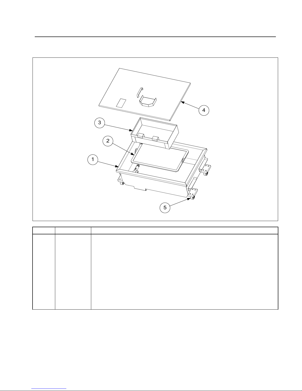
2.8 Filter Unit
YSCFC SERIES FLATBOTTOM GAS FRYERS
CHAPTER 2: PARTS LIST
ITEM PART # COMPONENT
1 106-8465SP Filter Pan (with 2" casters)
2 810-2800 Filter Leaf
3 823-5833 Crumb Basket
4 106-6131 Lid, Filter Pan
5 810-2805 Caster, 2"
* 826-1392 O-rings (for filter pan pick up tube; qty. 5)
* 816-0757 O-rings (for filter leaf)
* 803-0342 Filter Powder (pack of 25)
* 803-0289 Filter Paper, 22" x 34" (if using paper option)
* 220-1145 Sana Grid Screen (if using paper option)
* 810-3082 Hold Down Ring (if using paper option)
* Not illustrated.
2-13

YSCFC SERIES FLATBOTTOM GAS FRYERS
CHAPTER 2: PARTS LIST
2.9 Frypot, Drain, and Oil Return Components
2-14

YSCFC SERIES FLATBOTTOM GAS FRYERS
CHAPTER 2: PARTS LIST
2.9 Frypot, Drain, and Oil Return Components (cont.)
ITEM PART # COMPONENT
1 826-1823 Frypot Kit, 1824G (insulation included)
826-1821 Frypot Kit, 2424G (insulation included)
2 823-3934 Divider, Frypot
3 823-3174 Plug, Frypot Drain
4 823-3190 Baffle, Secondary Air
5 210-1409 Spreader, Side Flame
6
823-5854 1824 (use with 823-5195 on 1824 units)
823-5195 2424 (use with 823-5854 on 1824 units)
* 826-2036 Insulation, Pot FB
7 220-3512 Guard, Firebox, Bottom
8 812-1822 Tube, Drain, RH
9 812-1823 Tube, Drain, LH
10 812-2017 Tube, Drain, Center Dump
11 816-0772 Sleeve, Drain Tube Connector
12 809-0969 Clamp, 3" T-bolt
13 106-5461
810-2125 Drain Valve, ⅜" Ball Valve
810-3011 Tubing, Front
810-3014 Tubing, Rear
813-0165 Elbow, ½" x ½" Street , 90°
813-0462 Coupling, ⅜"
813-0613 Fitting, ½" x ½" 37° Flare
813-0614 Fitting, ½" x ⅜" 37° Flare
813-0631 Elbow, ⅜" x 90°
813-0649 Nipple, ⅜" NPT x 2.50 inch
813-0894 Elbow, ½" x ⅜" 37° Flare
14 106-4006 Drain Valve with Microswitch, ½"
* 816-0547 Sleeve, Red Valve Handle
* 807-2104 Microswitch, Drain Valve Roller Lever (use 902-2348 for M/S Guard)
* 813-1790 Nipple, 1¼" x 5.85 inch NPT Toe
* 813-0165 Elbow, ½" x 90° NPT Street
* 813-0632 Elbow, ⅜" x 90° NPT Street
* 810-2125 Valve, ⅜", Oil Return, Ball (use 200-1143 for Nut Retainer)
* 823-5815 Handle, Oil Return
* 810-3014 Tube, Front Oil Return
* 200-4725 Guard, Probe and High-Limit
* 210-1433 Clamp, Probe and High-Limit Bulb
* 200-4505 Plate, Drain Nipple Closure
* 812-1515 Nipple, ⅜" x 2.345" NPT Toe
* Not illustrated.
Firebox Assembly
Oil Return Plumbing (attaches to Item 21, Section 2.4, at the back of the unit)
2-15

YSCFC SERIES FLATBOTTOM GAS FRYERS
CHAPTER 2: PARTS LIST
2.10 Drain Valve and Components
7
8
11
9
10
6
5
4
3
2
1
ITEM PART # COMPONENT
1 810-2867 Valve, Drain 1¼" (1" Std. Port)
2 200-8867 Strap, 3" Drain
3 106-6020 Bracket Assembly
4 816-0220 Insulation
5 807-2103 Switch, Micro CE Straight Lever
6 220-3517 Cover, Safety Switch
7 826-1366 Nut, 4-40 Keps Hex (Pkg. of 25)
8 809-0988 Washer, 1" OD x .525" ID Teflon
9 200-1257 Retainer, Nut, Drain Valve
10 823-4883 Handle, Drain Valve
11 816-0547 Sleeve, Plastic, 1 ¼" Red
2-16
YSCFC SERIES FLATBOTTOM GAS FRYERS
CHAPTER 2: PARTS LIST
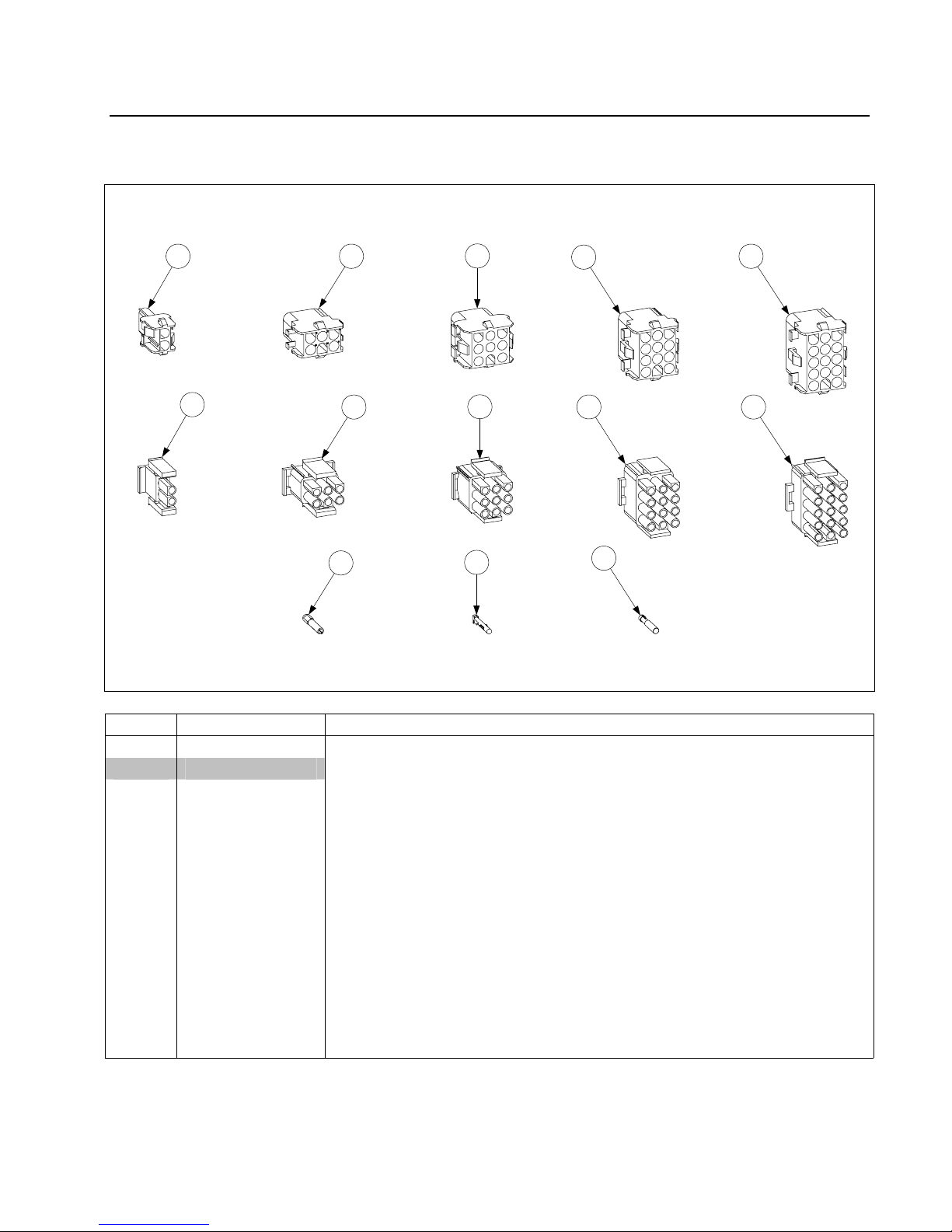
2.11 Wiring Connectors, Pin Terminals, and Power Cords
1 2
6
11
7 9 10
3
8
12
4
13
ITEM PART # COMPONENT
* 106-7649 Power Cord Assembly 120V 10’ 16 gauge
Connectors
1 807-1068 2-Pin Female
2 807-0158 6-Pin Female
3 807-0156 9-Pin Female
4 807-0159 12-Pin Female
5 807-0875 15-Pin Female
6 807-1067 2-Pin Male
7 807-0157 6-Pin Male
8 807-0155 9-Pin Male
9 807-0160 12-Pin Male
10 807-0804 15-Pin Male
11 826-1341 Terminal, Female Split Pin (Pkg. of 25)
12 826-1342 Terminal, Male Split Pin (Pkg. of 25)
13 807-2518 Plug, Mate-N-Lock (Dummy Pin)
* Not illustrated.
5
2-17

YSCFC SERIES FLATBOTTOM GAS FRYERS
CHAPTER 2: PARTS LIST
2.12 Screws, Nuts, and Fasteners
ITEM PART # COMPONENT
* 826-1389 Screw, ¼-20 x ¾" (Pkg. of 10)
* 826-1359 Screw, 4-40 x ¾" Slotted Round Head (Pkg. of 25)
* 809-0853 Screw, 10-32 x 1.5" Slotted Pan Head
* 809-0839 Screw, 8-32 x .75" Slotted Pan Head
* 809-0918 Screw, 10-24 x ½"
* 826-1371 Screw, #8 x .50" Slotted Hex Head (Pkg. of 25)
* 826-1374 Screw, #10 - ½" Hex Washer Head (Pkg. of 25)
* 809-0766 Nut, 10-32 Hex Head
* 809-0823 Nut, ¼-20 Nylock
* 809-0247 Nut, 8-32 Keps
* 809-0834 Nut, 8-32 Hex Locknut
* 809-0050 Nut, 8-32 Hex Zinc Plated
* 826-1366 Nut, 4-40 Keps (Pkg. of 25) (used to mount microswitch)
* 826-1362 Nut, ¼-20 Hex, Zinc Plated
* 809-0987 Nut, ¼-20 Press, Stainless Steel
* 809-0885 Washer, Flat ⅜" x 1" x .083”
* 809-0191 Washer, ¼" Lock
* Not illustrated.
2-18

Frymaster/Dean, 8700 Line Avenue, Shreveport, Louisiana 71106
TEL 1-318-865-1711 FAX (Parts) 1-318-688-2220 FAX (Tech Support) 1-318-219-7135
PRINTED IN THE UNITED STATES
SERVICE HOTLINE
1-800-551-8633
819-6472
FEB 2009
 Loading...