

Page 1
SERVICE MANUAL
UNIVERSAL HOLDING CABINET (UHC)
MANUFACTURED BY
P.O. BOX 51000
SHREVEPORT, LOUISIANA
71135-1000
PHONE 1-318-865-1711
1-800-24 FRYER
Universal Holding Cabinet 1-1
Power Up 2-1
Operational Overview 3-1
Operator Mode 4-1
Timer Operation 5-1
Cook More Prompts 6-1
Switching Between Breakfast. Lunch, Clean Mode and Slot Off 7-1
Slot Temperature Display 8-1
Temperature Alarms 9-1
Product Selection 10-1
Program Mode 10-1
Page Selection 10-2
Meal Selection 10-3
Exiting Program Mode 10-5
Example of Production Selection Change 10-6
Entering and Editing Product Information 11-1
Entering Password 11-1
Entering Product Name 11-1
Entering Product Holding Time 11-3
Enter Meal Usage 11-4
Display Adjustments 12-1
Change Display Time 12-1
Change Display Intensity 12-1
Change F° to C°
Troubleshooting Guide 13-1
Diagnostic Tests 14-1
Service Procedures 15-1
Parts Lists, Exploded Views 16-1
Wiring Diagram 17-1
Appendices 18-1
Appendix A: Food Item Default Settings 18-1
Appendix B: Cleaning and Preventive Maintenance 18-2
Appendix C: RTD Resistance Chart 18-4
Appendix D: SOC for Universal Holding Cabinet 18-5
Appendix E: Production Charts 18-6
Appendix F: Quick Reference Guide 18-7
Appendix G: Typical Setups/Stacked Arrangements 18-8
12-1
Frymaster L.L.C., 8700 Line Avenue 71106, 5489 Campus Drive 71129
P.O. Box 51000, Shreveport, Louisiana 71135-1000
PHONE 318-865-1711 FAX 318-219-7135
PRINTED IN THE UNITED STATES SERVICE HOTLINE 1-800-24-FRYER 819-5551A 10/00
Page 2

1 Universal Holding Cabinet
The Frymaster Universal Holding Cabinet (UHC) developed and manufactured exclusively for
McDonald’s, is a short-term holding device to extend the freshness of a wide variety of cooked
products. The UHC meets all McDonald’s standards for safety, efficiency, and cleanliness.
1.1 Warranty Statement
A. Frymaster L.L.C. makes the following limited warranties to the original purchaser only for
this equipment and replacement parts:
1.1.1 Warranty Provisions – Universal Holding Cabinet
A. Frymaster L.L.C. warrants all components against defects in material and workmanship for a
period of two years.
B. All parts, with the exception of fuses, are warranted for two years after installation date of
cabinet
C. If any parts, except fuses, become defective during the first year after installation date,
Frymaster will also pay straight-time labor costs to replace the part, plus up to 100 miles/160
km of travel (50 miles/80 km each way).
1.1.2 Parts Return
A. All defective in-warranty parts must be returned to a Frymaster Authorized Factory Service
Center within 60 days for credit. After 60 days, no credit will be allowed.
1.2.3 Warranty Exclusions
• This warranty does not cover equipment which has been damaged due to misuse, abuse,
alteration, or accident such as:
• Improper or unauthorized repair;
• Failure to follow proper installation instructions and/or scheduled maintenance
procedures as prescribed in your MRC cards;
• Improper maintenance;
• Damage in shipment;
• Abnormal use;
• Removal, alteration, or obliteration of the rating plate;
This warranty also does not cover:
• Transportation or travel over 100 miles/160 km (50 miles/80 km each way), or travel
time over two hours;
• Overtime or holiday charges;
• Consequential damages (the cost of repairing or replacing other property that is
damaged), loss of time, profits, use or any other incidental damages of any kind.
1-1
Page 3

There are no implied warranties or merchantability or fitness for any particular use of purpose.
For international warranty, the above procedures apply, except that the customer is responsible for
freight and duty charges.
PARTS ORDERING AND SERVICE INFORMATION
Parts orders may be placed directl y with your local Frymaster Factory Authorized Service Center
(FASC)/Distributor. A list of Frymaster FASC/Distributors was included with the cabinet when
shipped from the factory. If you do not have access to this list, please contact the Frymaster Service
Department at 1-800-24-FRYER or 1-318-865-1711.
Please note that orders for wi re/plastic trays, stacking kits, carts and casters should be p laced
with your local Kitchen Equipment Supplier (KES). Frymaster does not supply these
accessory items.
To speed up your order, the following information is required:
Model Number_____________________________________
Serial Number_____________________________________
Voltage___________________________________________
Item Part Number___________________________________
Quantity Needed____________________________________
Service may be obtained by contacting your local Frymaster Authorized Service Cent er/Distributor.
Service information may be obtained by calling the Frymaster Service Department. The following
information will be needed in order to assist you quickly and efficiently:
Model Number_____________________________________
Serial Number______________________________________
Nature of the
Problem___________________________________________________________________
Also any other information which may be helpful in solving your service problem.
RETAIN AND STORE THIS MANUAL IN A SAFE PLACE FOR FUTURE USE.
1-2
Page 4

1.2 Product Trays
There are 3 product tray sizes. See Appendices A and C for specific product volumes and
recommended holding sizes and times. Use the tray that is designed for the specific product
described below:
A. 1/3-size plastic tray – Holds meat and egg products that are grilled (hamburger patties,
bacon, eggs, sausage, etc.) There are two important procedures to rememb er when storing
grilled products:
• The product should not be drained when picked up from the grill.
• The product is stacked when placed in the proper tray. 10-1 and sausage patties can be
stacked up to six high. Eggs (except scrambled), grilled chicken and 4-1 patties can be
stacked up to three high.
B. 1/2-size wire tray – holds fried products (McNuggets, McChicken, Filet-O-Fish, etc.)
Remember this important procedure when storing fried products:
• Fried products are to be placed on the wire rack. The rack should be placed on a crumb
tray. No tray liners are required for these trays.
C. Full-size plastic tray – holds baked products (biscuits, muffins, etc.) Follow these
procedures for baked products:
• After the biscuits have been removed from the biscuit oven, remove the wrapper and
open the cardboard box.
• Put a tray liner in the tray and slide the biscuits onto the liner. The biscuit trays can hold
up to 30 frozen biscuits, 20 scratch biscuits or 20 muffins.
Important Operational Tips
When placing a tray into the cabinet, make sure the slot line on the tray handle lines up with the edge
of the slot.
Discard cracked or damaged trays.
When removing portions from a tray, slide the tray only as far as needed, then quickly return the tray
to the slot line.
1-3
Page 5
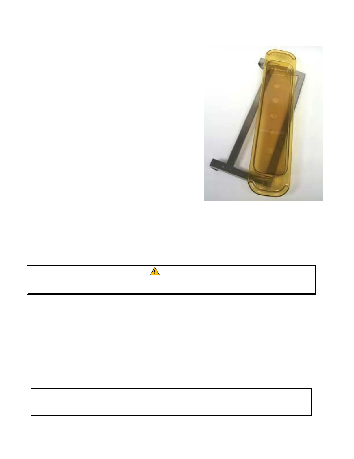
1.3 Install Grill Clip
The grill clip is shipped in the accessory package and is
designed to hold the 1/3-size grill tray. It attaches to the
grill to make transfer from the grill to the UHC faster and
safer.
• Position the front of the grill clip under the lip
of the grill.
• Lower the back of the clip until the grooves rest
over the grill bar. The grill clip should firmly
seat on the front of the grill. If the clip doesn’t
fit snuggly, simply loosen the four nuts under
the clip and slide it in or out as needed to tighten
against the bar. Tighten the nuts after the clip is
properly adjusted.
The grill clip attaches to the grill and holds
grilled product in a UHC tray, making
transfer to the holding cabinet easier.
1.4 Installation of 4” Legs
CAUTION
Use caution when handling the cabinet or tilting the unit to/from the floor to install
the legs. Maneuvering the cabinet should be accomplished by at least tw o people.
A. Carefully place the Universal Holding Cabinet on its right side (direction is determined with
you facing the front of the unit), exposing the base of the cabinet.
B. Mount the leg pads to the bottom of the base using the 16-¼"-20 x ½" long screws and
lockwashers provided.
C. Screw the leg into the mounted leg pad until fully tight.
D. Carefully turn the UHC upright until the unit stands on its legs. Perform Step 2, Power Up.
IF THE UHC IS INSTALLED WITH THE COUNTERTOP OPTION, ENSURE THE
AREA WHERE THE UHC BASE AND COUNTERTOP MEET IS PROPERLY SEALED
WITH A FOOD GRADE TYPE SEALANT.
1-4
Page 6

2 Power Up
ALL ELECTRICALLY OPERATED APPLIANCES MUST BE ELECTRICALLY
GROUNDED IN ACCORDANCE WITH LOCAL CODES, OR IN THE ABSENCE OF
LOCAL CODES, WITH NATIONAL ELECTRIC CODE, ANSI/NFPA NO. 70-1990.
A. Power Requirements:
• Voltage – 208/240 VAC
• 2620 Watts @ 208V – 3420 Watts @ 240V
• Frequency – 50/60 Hertz
• Single Phase
• 20 amp Service
THIS APPLIANCE IS EQUIPPED WITH A THREE-PRONG GROUNDING PLUG FOR
YOUR PROTECTION AGAINST SHOCK HAZARD AND MUST BE PPLUGGED INTO A
PROPERLY GROUNDED THREE-PRONG RECEPTACLE. DO NOT CUT OR REMOVE
THE GROUNDING PRONG FROM THIS PLUG.
B. Plug the Universal Holding Cabinet into the power source.
C. Place the power switch in the ON position. All control displays will illuminate green
approximately 2 seconds after the power switch is activated.
D. Monitor the temperature of the slots. The time it takes the slot(s) to heat from ambient (room)
temperature to a 155°F (68°C) setpoint should be approximately 15 minutes. It should take
approximately 25 minutes to reach a 200°F (93°C) setpoint. If setpoint is not consistently
achieved within these limits, call your local Factory Authorized Service Center for repair.
2-1
Page 7
3 Operational Overview
The Universal Holding Cabinet (UHC) has either four slots that can hold up to three trays of product per slot
or two slots, which hold up to three trays. Each slot has a controller that indicates the holding time and
product selection for each tray position.
Universal Holding Cabinet (UHC)
The operator enters information into the controller via the display and keypad shown below. Each product
selection has a temperature setpoint and product holding time. All product timers run independently. The
slot temperature is controlled by the temperature setpoint of the leftmost product entry in each slot as
viewed from the front of the cabinet. Product selections that have a holding temperature different that
the leftmost product selection will not be available for entry into that slot’s configuration.
Most UHC’s have a front and rear display for each slot. All operator mode selections can be made from
either display. Program changes can only be made from the front display. A Special Point of Distribution
(SPOD) cabinet has only a front controller for each slot.
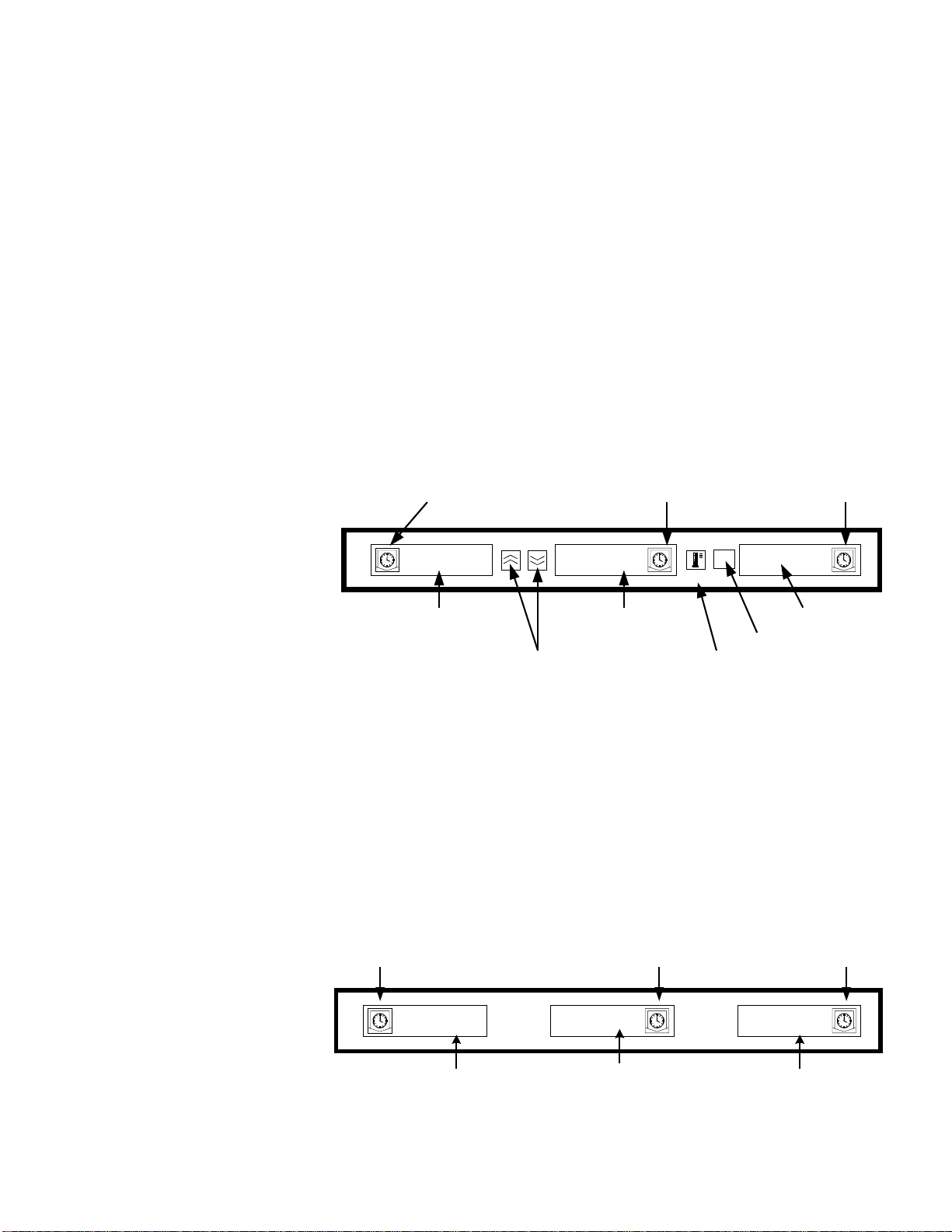
UHC Controller (Front Display and Keypad)
Timer keys (Left, Center, and
Left Timer Key
Center Timer Key
Right Timer Key
Right) start and stop the timer
associated with each tray
position. The timer keys also
turn off audible alarms.
Displays (Left, Center, and
Right) show product selection
and holding time for each tray
position. The displays also
provide programming
SAUS
SAUS SAUS
SAUSSAUS
Left Display
UP/DOWN Arrow Keys
SAUS SAUS
SAUSSAUS
Center Display
ENTER
MENU
PAGE
Temperature/Enter
SAUS
SAUSSAUS
Right Display
Menu Key
/Page Key
information in program mode.
MENU key is used to select meal transitions (breakfast to lunch), Clean Mode operation and to turn
individual slots on or off. The MENU key also provides access to program mode.
TEMPERATURE/ENTER/PAGE key has three functions. 1) Display slot temperature information; 2)
Enter operational changes; and 3) Select Page parameters in program mode.
Up and Down ARROW keys are used to increase/decrease variables or change selections.
UHC Controller (Rear
Display and Keypad,
Traditional UHC Only)
Left Timer Key
Center Timer Key
SAUS SAUS SAUS
Left Display
Center Display Right Display
3-1
Right Timer Key
Page 8

4 Operator Mode
Operator Mode is the normal operating mode of the controller when all slots are at the proper
temperature and no alarm conditions exist. Product information and holding time is displayed.
4.1 Display of Product Information
In Operator Mode the slot display indicates the following:
1. The product selection for a tray location.
2. The holding time remaining (in minutes) for active timers.
An active timer alternately displays the product selection and the time remaining. Inactive timers
display only product selection.
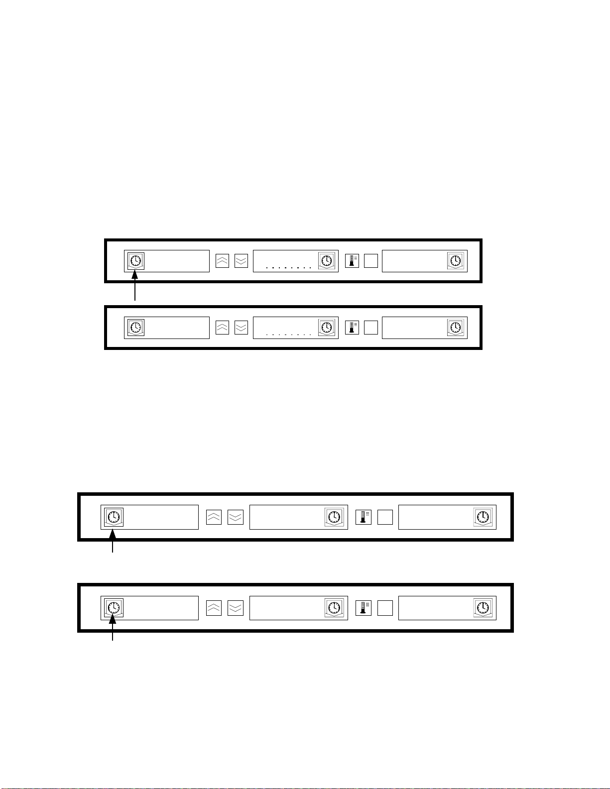
4.2 Product Information and the Use First Display
The Operator Mode indicates product selection and holding time status by changing the display
intensity.
The “Use First Display” indicates the product with the least amount of holding time remaining.
There are two levels of display intensity used to indicate product status.
1. Brighter level of display intensity and running dots indicate the “use first” product
selection.
2. Lower level of display intensity indicates:
a. An active timer that is not the product selection with the least holding time remaining.
b. An inactive timer where only the product selection is displayed.
Timer Status Indicators
SAUS
SAUS
SAUSSAUS
Use-First Timer
Higher Intensity
12
12
1212
ENTER
PAGE
ENTER
PAGE
MENU
SAUS
SAUSSAUS
Inactive Timer
Lower Intensity
MENU
SAUS
SAUSSAUS
SAUS
SAUS SAUS
SAUSSAUS
Active Timer
Lower Intensity
20
20 SAUS
2020
Running Dots
4-1
Page 9
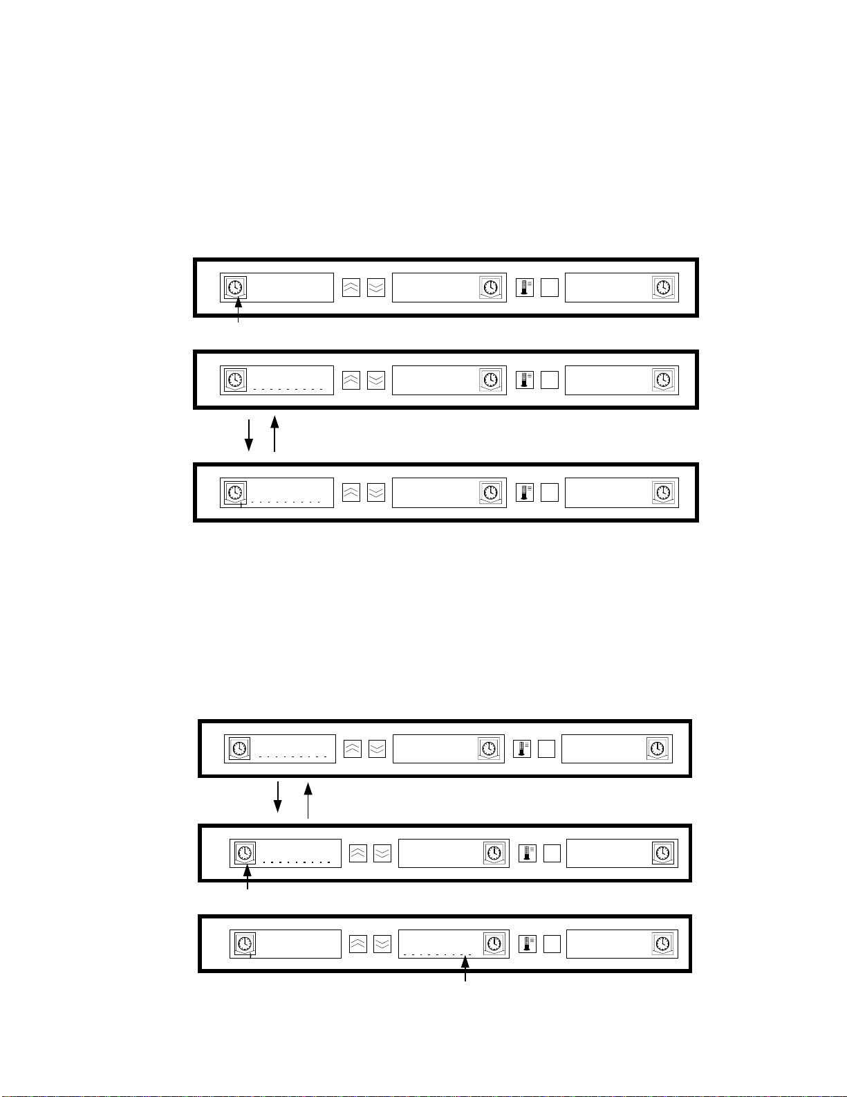
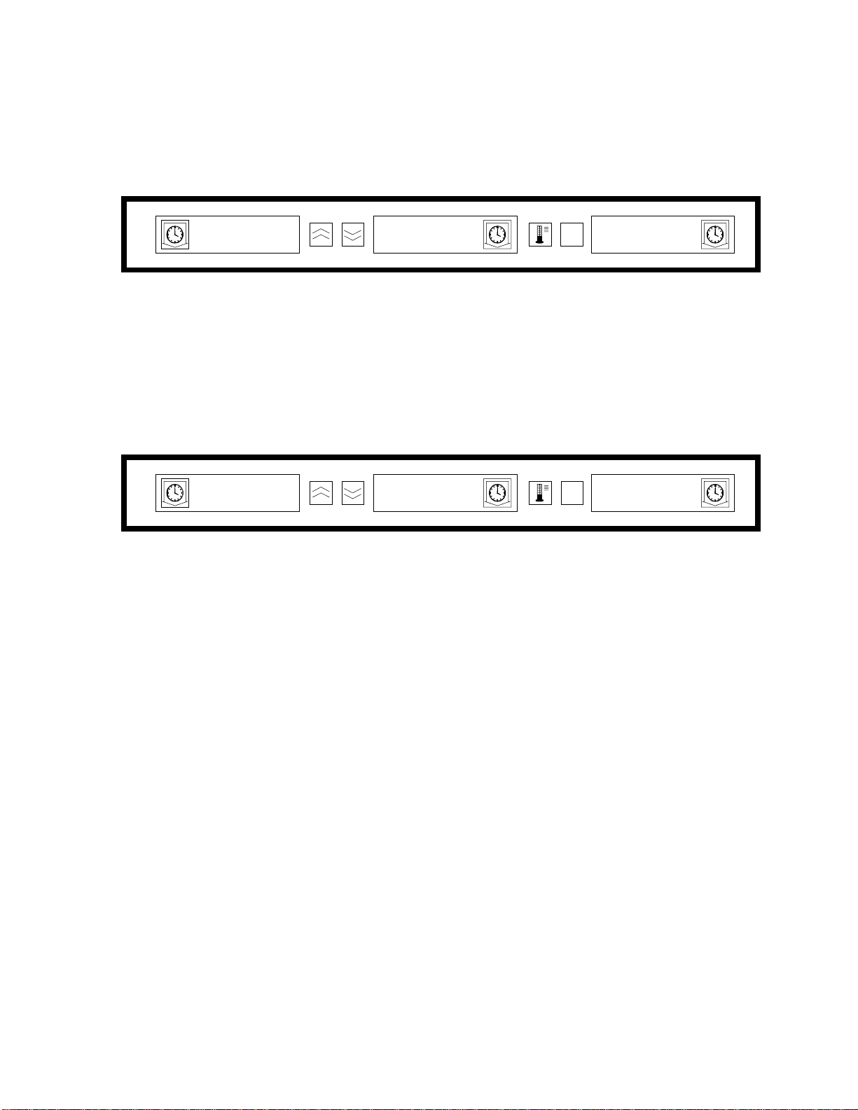
5 Timer Operation
5.1 Starting A Timer
Press the Timer key above the tray position to start a timer. The timer will time down from a
preset value and alternately display product selection and the holding time remaining. If more than
one tray of a product selection is timing, the location of the product with the least remaining holding
time is indicated by the Use First display status.
ENTER
SAUS
SAUS SAUS
SAUSSAUS
Press TIMER key to start a timer
60
60 SAUS
6060
Active display alternately indicates
holding time and product selection
SAUS
SAUS SAUS
SAUSSAUS
SAUS SAUS
SAUSSAUS
SAUS SAUS
SAUSSAUS
SAUS SAUS
SAUSSAUS
PAGE
ENTER
PAGE
ENTER
PAGE
MENU
MENU
MENU
SAUS
SAUSSAUS
SAUS
SAUSSAUS
SAUS
SAUSSAUS
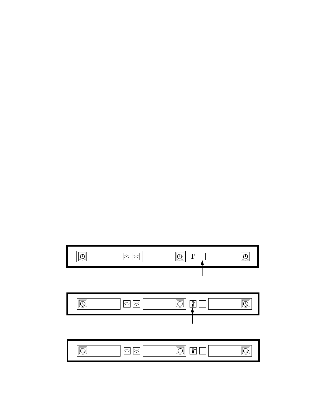
5.2 Stopping A Timer
Press the Timer key above the slot position to turn off an active timer. The timer stops timing
and the display changes to the inactive timer status. If more than one tray of a product selection is
timing, use first indication changes to next active timer.
Timer to Stop
SAUS
SAUS SAUS
SAUSSAUS
Active display alter n ately indicates
holding time and product selection
19
19 24
1919
Press TIMER key to stop timer
SAUS
SAUS SAUS
SAUSSAUS
Next Shortest Time
ENTER
SAUS SAUS
SAUSSAUS
24 SAUS
2424
SAUS SAUS
SAUSSAUS
PAGE
ENTER
PAGE
ENTER
PAGE
Inactive Timer
MENU
SAUS
SAUSSAUS
MENU
MENU
SAUS
SAUSSAUS
SAUS
SAUSSAUS
Use-First indication changes to next
active timer
5-1
Page 10
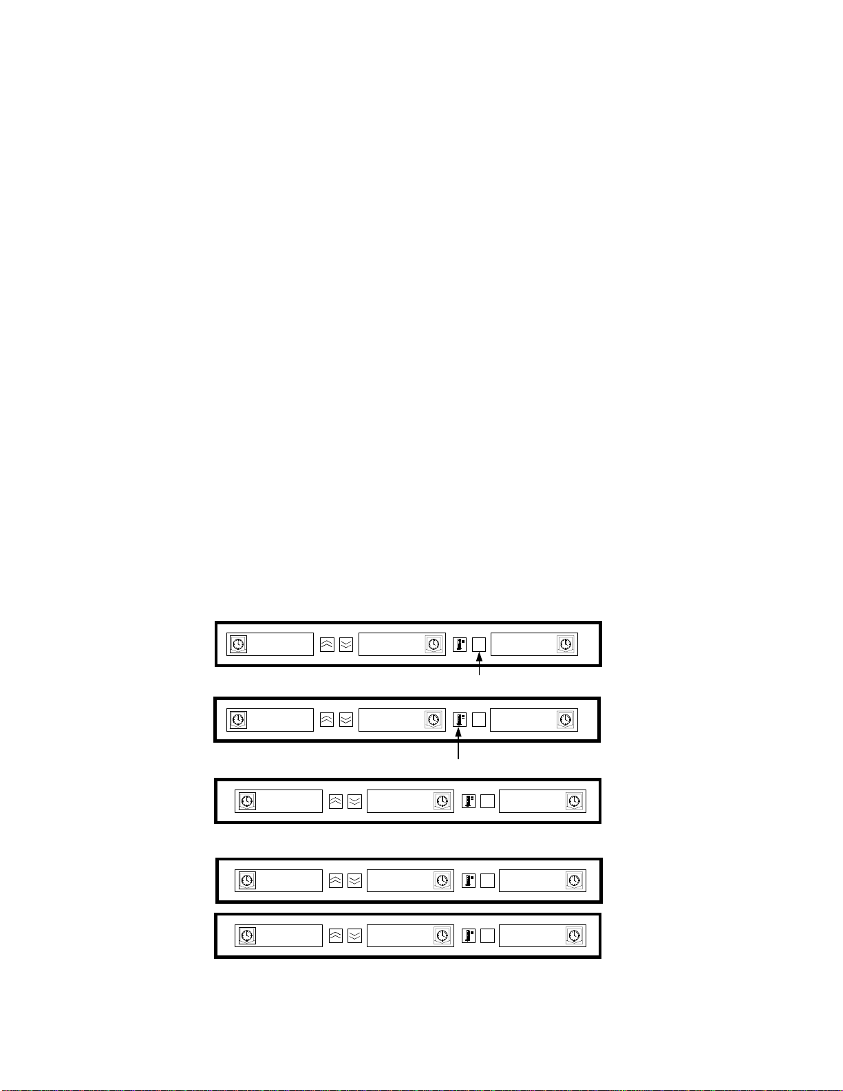
5.3 Timing Out
Time out indication alerts the operator that the product holding time has expired. When the
holding time remaining reaches zero an audible alarm sounds and the display indicates -00-
-00-. All
-00--00-
other active displays in the cabinet will switch to the lowest intensity level until the audible alarm is
turned off.
Press the Timer key of the timed-out timer to clear th e timer an d turn off the audibl e alarm. If
other timers in the cabinet have timed out, the audible alarm will remain on until all timers are
cleared. When all timers are cleared, active timers return to normal status. Use First status is
switched to the next timer with the least holding time remaining.
Timed Out Timer Next Shortest Time Inactive Timer
ENTER
-00-
-00-
-00--00-
Press TIMER key to turn of audible alarm
SAUS
SAUS
SAUS
SAUS
SAUSSAUS
PAGE
ENTER
PAGE
MENU
MENU
SAUS
SAUS
Display returns
to inactive
Use first status changes
to the next active timer.
5.4 Buffer Timer
This feature allows an operator to adjust the holding time for a specified product by pressing the
timer key. This means product can be transferred from a remote holding cabinet and the remaining
hold time entered into another UHC. Time adjustments are in 5-minute increments.
ENTER
60
6060
Initial Timer Display:
saus
saus
saussaus
Shown when timer
PAGE
MENU
saus
saus60
saussaus
is pressed after placing product in slot.
ENTER
Buffer Timer:
saus
saus
30
30
3030
saussaus
Pressing the timer button a
MENU
PAGE
saus
saus
saussaus
second time within three seconds allows 5minute decrease in holding time.
5-2
Page 11

5.4 Buffer Timer (cont.)
When the "Use First" tray of a product is placed in the cabinet, the product timer is activated by
pressing the corresponding timer key. The display immediately indicates the maximum holding time
for the product and changes to Display Intensity three (brightest). If the timer key is pressed within
3 seconds of activating the timer, the product holding time will decrease by 5 minutes for each key
press. If no timer key press occurs within 3 seconds, the display then alternately displays the
remaining holding time and product mnemonic.
The Timer Display Time (TIMR TIME) and Product Display Time (PROD TIME) v alues det ermine
how long (in seconds) that each message is displayed. Default settings for these values are 5
seconds and 1 second respectively.
To decrease the preset time, the holding time for each product, press the timer key and th e displayed
time will decrease in 5-minute increments each time the key is pressed. The timer key must be
pressed within 3 seconds. If you wait longer than three seconds, the timer will reset. Preset times are
the established holding times for each product. The Buffer Timer Feature is extremely useful when
transferring product from another holding cabinet.
5-3
Page 12
6 Cook More Prompts
The Cook More Prompts feature provides the operator with visual and audible notification that the
last tray of a specific food product will be expiring soon and it is time to cook more. This feature is
programmable, in one-minute increments, at the restaurant level.
ENTER
PAGE
ENTER
PAGE
MENU
MENU
saus
sauscook
saussaus
30
30cook
3030
more
more
cook
cookcook
When the holding time of a product equals a preset "cook more" time, an audible
alarm sounds for 3 seconds and the display will alternately display: the remaining
holding time / product mnemonic / COOK MORE.
- No acknowledgment of the audible alarm is required. It occurs only to get the
attention of the operator.
muff
muff
muffmuff
moremore
cook
cookcook
Cook More:
After accessing the Cook More feature, use the UP and DOWN arrow keys to
change the cook more time.
To change the cook more
- Press and hold the MENU key for 5 seconds
- Press the PAGE key to scroll to View Page
- Press MENU key to scroll to the Security Lock
- Press the Up and Down arrow keys to enter the manager security code 247
- Press the PAGE key to scroll to the Cook Page
- Press the MENU key to scroll to the Product Selection
- Press the Up and Down arrow keys to change the product cook more time
- Press and hold the MENU key for 5 seconds to return to normal operation
cook more time:
cook morecook more
6-1
Page 13
7 Switching Between Breakfast, Lunch, Clean Mode and Slot On/Off
Pressing the MENU key scrolls the following information for each slot.
1. The inactive meal product selection (breakfast or lunch).
2. Clean Mode.
3. Slot On/Off status.
Pressing the MENU key again returns the display to Operator Mode.
7.1 Selecting Breakfast and Lunch
To establish the breakfast and/or lunch menu, determine the type and number of product tray(s) to
use. The following is the established configuration of trays and products:
1/3-size plastic tray – holds meat and egg products that are grilled (hamburger patties,
bacon, eggs, sausage, etc.). Each slot can hold up to three trays of this type.
1/2 size plastic tray with wire insert – holds breaded fried products (McNuggets,
McChicken, Filet-O-Fish, etc.). Each slot can hold up to two trays of this type.
Full-size plastic tray – holds baked products (biscuits, muffins, etc.). Each slot can hold one
tray of this type.
To change the product selection of a slot from Breakfast to Lunch, press the MENU key to display
the lunch product selections. Press the ENTER key to activate the meal selection. If the ENTER
key is not pressed within 5 seconds, the product selection will return to the Breakfast meal selection.
Changing Meal Selection
ENTER
SAUS
NUGG
NUGG NUGG
NUGGNUGG
NUGG
NUGG NUGG
NUGGNUGG
NUGG
NUGGNUGG
NUGG
NUGGNUGG
Press ENTER key to enter meal selection
and return to normal display mode.
MENU
MENU
MENU
SAUSSAUS
NUGG
NUGG
NUGGNUGG
NUGG
NUGG
NUGGNUGG
PAGE
Press MENU key to display
inactive meal selection
ENTER
PAGE
ENTER
PAGE
NOTE: Active timers will not change to the new meal selection until the timer(s) are stopped or
timed out and reset. Active timer(s) are stopped by pressing the timer key. The default menu at
start up is for breakfast items.
7-1
Page 14
7.1 Selecting Breakfast and Lunch (cont.)
NOTE: Active timers will not change to the new meal selection until the timer(s) are stopped or
timed out and reset. Active timer(s) are stopped by pressing the timer key. The Breakfast menu is
the default at power up.
If the product selection for the meal has a holding temperature different that the curr ent meal, a hi gh
or low temperature-alarm message displays to alert the operator that the holding temperature is being
changed. To turn off the audible alarm pr ess any Timer Key. The display alternately indicates the
product selection and the alarm message until the slot temperature is within the preset limits. The
alarm message automatically resets when the slot temperature is within the preset limits.
To change the product selection of a slot from Lunch to Breakfast, press the MENU key to display
the Breakfast product selections. Press the ENTER key to activate the meal selection. If the ENTER
key is not pressed within 5 seconds the product selection will return to the Lunch meal selection.
7.2 Clean Mode
Clean Mode changes the temperature setpoint of all slots in the cabinet to 125°F (52°C).
Starting Clean Mode
To start the Clean Mode press the MENU key to scroll to the Clean Mode message CLN MODE.
Press the ENTER key to activate the Clean Mode. All slots in the cabinet will change to Clean
Mode. If the ENTER key is not pressed within 5 seconds, the product selection will return to the
previous meal selection. If the slot temperature is above 125°F (52°C), the display will alternately
indicate SLOT CLN MODE and NOT SAFE YET. Th e display will indicate SAFE TO CLN
when the slot temperature is 125°F (52°C).
ENTER
SAUS
Press MENU key to scroll to clean mode message
CLN
CLN
CLNCLN
Press ENTER key to enter start Clean Mode
SLOT
SLOT CLN
SLOTSLOT
Display alternates messages if temperature is above safe level.
NOT
NOT SAFE
NOTNOT
CLN
CLNCLN
SAFE
SAFESAFE
PAGE
ENTER
PAGE
ENTER
PAGE
ENTER
PAGE
MENU
MENU
MENU
MENU
SAUSSAUS
MODE
MODE
MODEMODE
MODE
MODE
MODEMODE
YET
YET
YETYET
ENTER
MENU
CLN
CLN
SAFE
SAFE TO
SAFESAFE
To exit Clean Mode, press the MENU key to display the Clean Mode message. Press ENTER to exit
the Clean Mode and return to normal operation. The slot will alternately display SLOT TEMP LOW
and the product selection until the temperature is within normal operating limits. If the ENTER key is
not pressed within 5 seconds, the slot will return to the Clean Mode.
TO
TOTO
PAGE
CLNCLN
7-2
Page 15
Exit Clean Mode
To exit Clean Mode press the MENU Key to display the Clean Mode message. Press ENTER to
exit the Clean Mode and return to normal operation. The Slot will alternately display SLOT
TEMP LOW and the product selection until the temperature is within normal operating limits. If
the ENTER key is not pressed within 5 seconds the slot will return to the Clean Mode.
ENTER
TO
CLN
CLN
EXIT
EXIT
EXITEXIT
SAUS
SAUS SAUS
SAUSSAUS
CLNCLN
SAUS
SAUSSAUS
Press MENU key to display exit
CLN Mode message
Press ENTER key to exit Clean Mode and
return to normal display mode
PAGE
ENTER
ENTER
PAGE
PAGE
MENU
MENU
MENU
CLNSAFE
MODE
MODE
MODEMODE
SAUS
SAUS
SAUSSAUS
7.3 Slot On/Off
To turn a slot off, press the MENU key to scroll to the slot off message TURN SLOT OFF.
Press the ENTER key to enter the selection. The display will read SLOT IS OFF. If the ENTER
key is not pressed within 5 seconds, the product selection returns to the Operator Mode.
Turning Slot Off
ENTER
SAUS
SAUS
SAUS
SAUSSAUS
EXIT
EXIT
EXITEXIT
SLOT
SLOT 15
SLOTSLOT
SAUSSAUS
CLN
CLN
CLNCLN
15
1515
Press MENU key to scro ll to Slo t
Off message.
Press ENTER key to turn slot off.
PAGE
ENTER
PAGE
ENTER
PAGE
MENU
MENU
MENU
SAUS
SAUSSAUS
SAUSSAUS
MODE
MODE
MODEMODE
OFF
OFF
OFFOFF
7-3
Page 16
Turning Slot On To turn a slot on, press the MENU key to scroll to the slot on message (TURN SLOT ON). Press the
ENTER key to enter the selection and return to the Operator Mode. The slot alternately displays
SLOT TEMP LOW and the product selection until the temperature is within normal operating limits.
If the ENTER key is not pressed within 5 seconds the slot returns to the SLOT OFF status.
ENTER
15
15
SLOT
SLOTSLOT
TURN
TURN
TURNTURN
SAUS
SAUS SAUS
SAUSSAUS
1515
SLOT
SLOT
SLOTSLOT
SAUS
SAUSSAUS
Press MENU key to scroll to Slot
ON message.
Press ENTER key to turn slot ON and
return to normal display mode.
PAGE
ENTER
PAGE
ENTER
PAGE
MENU
MENU
MENU
OFF
OFFSLOT
OFFOFF
ON
ON
ONON
SAUS
SAUS
SAUSSAUS
7-4
Page 17
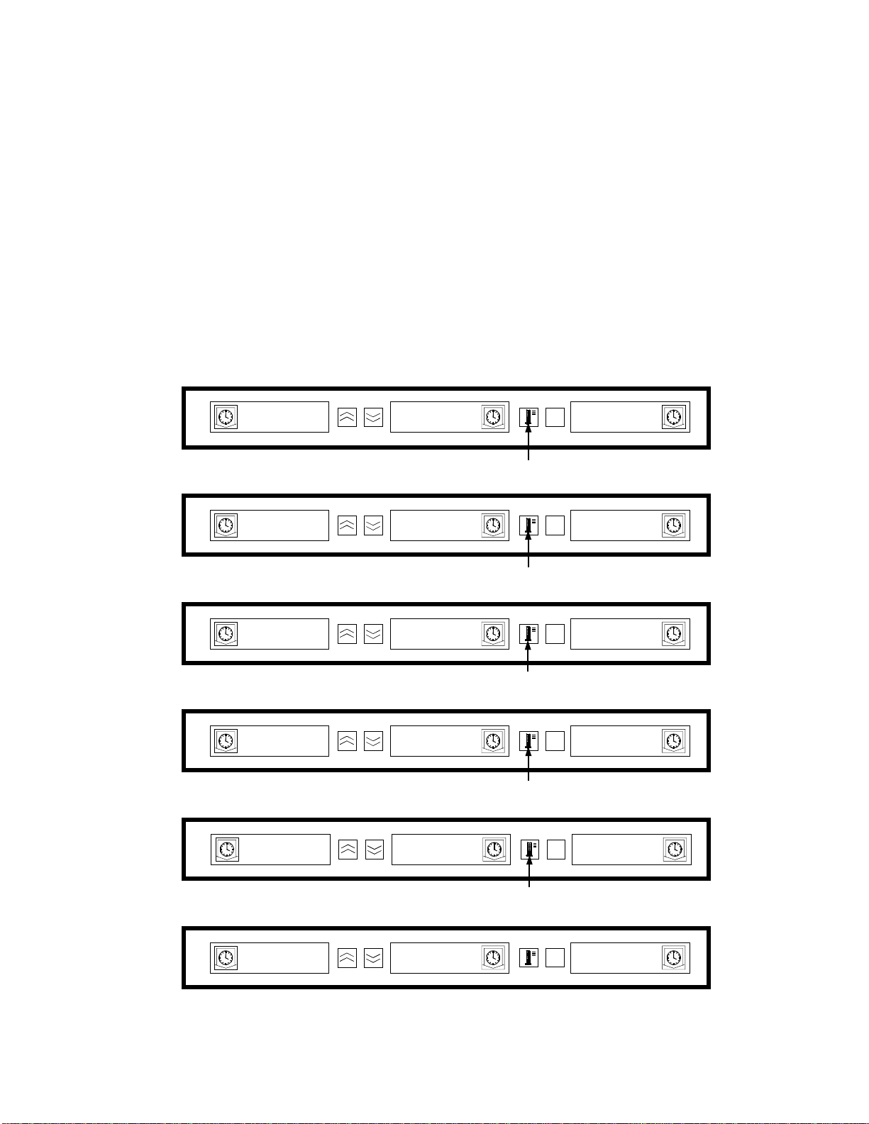
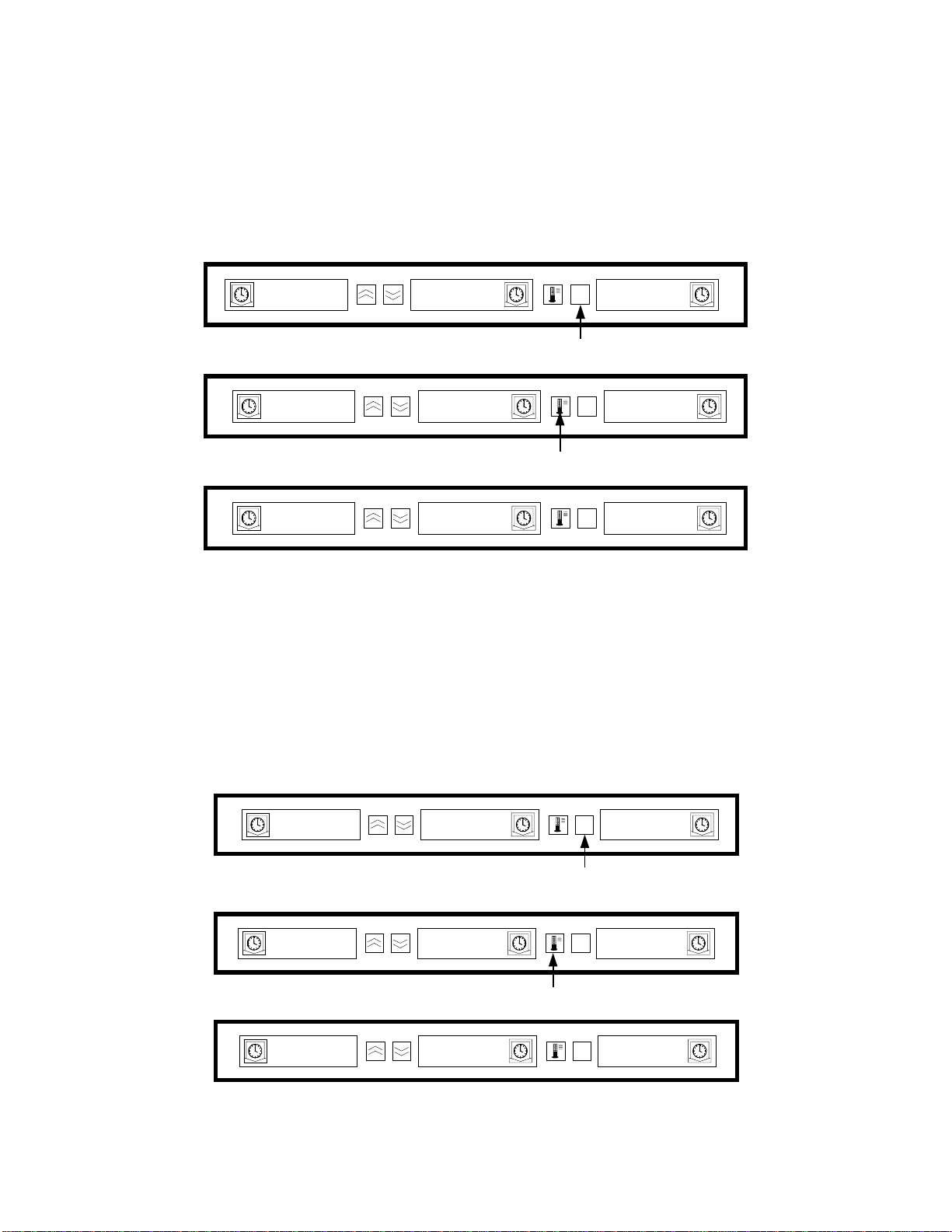
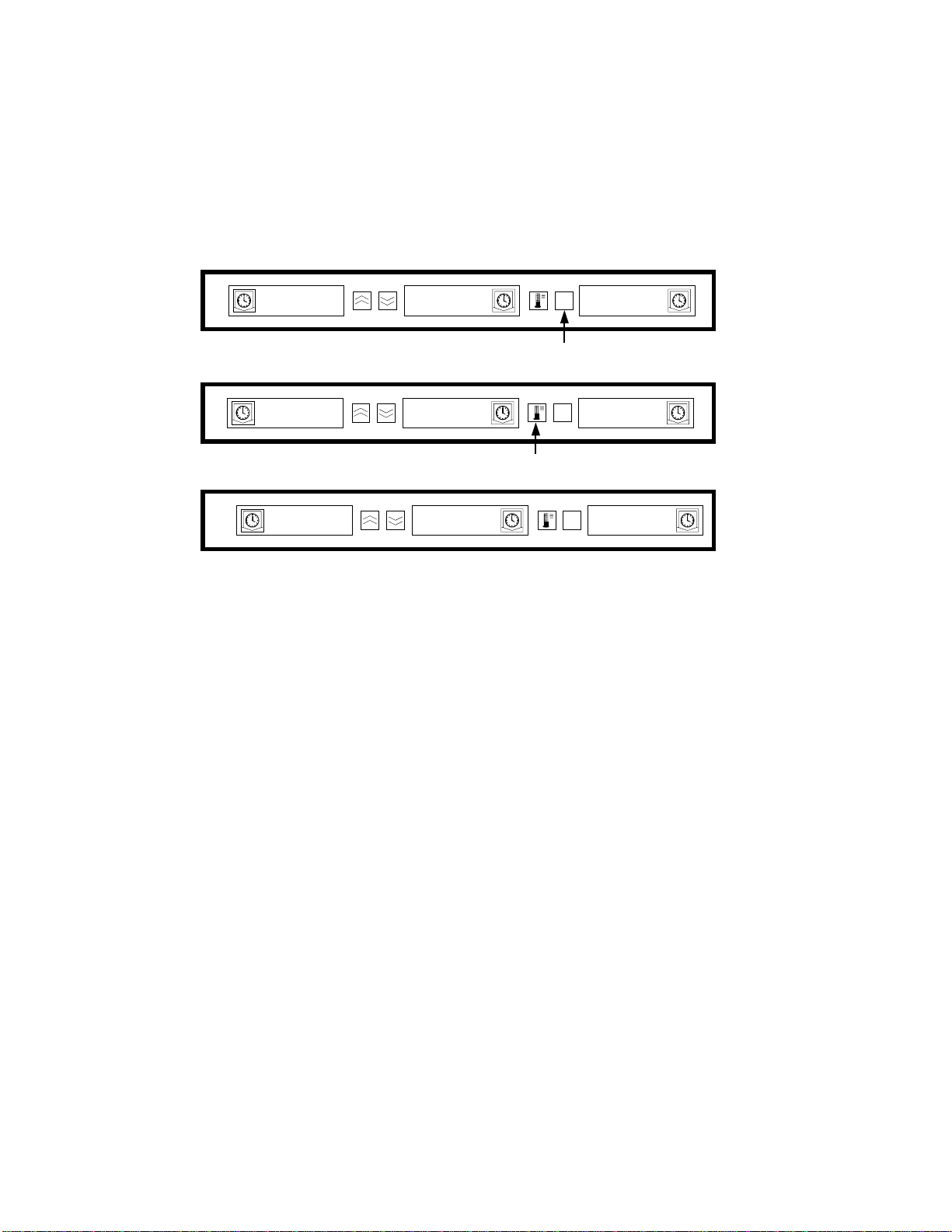
8 Displaying Slot Temperature Information (Temperature Key)
Pressing the Temperature/ENTER/PAGE key scrolls the following temperature information for
each slot.
1. Top plate temperature
2. Bottom plate temperature
3. Top plate setpoint
4. Bottom plate setpoint
Pressing the ENTER key again will return the display to Operator Mode. The display will
automatically return to Operator Mode if no key is pressed for 5 seconds.
Shelf Temperature Display
ENTER
SAUS
SAUSSAUS
SAUS
SAUS
SAUSSAUS
Press temperature key to display top plate
temperature.
PAGE
MENU
SAUS
SAUSSAUS
SAUSSAUS
TEMP
TEMP
TOP
TOP
TOPTOP
BOT
BOT TEMP
BOTBOT
top
top tset
toptop
saus
saus saus
saussaus
TEMPTEMP
Press temperature key to display bottom
plate temperature.
TEMP
TEMPTEMP
Press temperature k ey to display top plate
setpoint temperature.
tset
tsettset
Press temperature key to display bottom
plate setpoint temperat ure.
saus
saussaus
Press temperat ure key to return to normal
display mode.
ENTER
PAGE
ENTER
PAGE
ENTER
PAGE
ENTER
PAGE
MENU
MENU
MENU
MENU
160
160
160160
160
160
160160
160
160
160160
saus
saus
saussaus
SAUS
SAUS saus
SAUSSAUS
saus
saussaus
8-1
ENTER
PAGE
MENU
saus
saus
saussaus
Page 18

9 Temperature Alarms
There are five temperature alarm functions:
1. High Temperature Alarm
2. Low Temperature Alarm
3. FDA Alarm
4. Sensor Alarm
5. Rise Time Alarm
If alarm conditions occur an audible alarm will sound and the displays will alternately display the
product selection and alarm message. Timers cannot be started when a slot is in alarm condition.
9.1 High and Low Temperature Alarm
If the slot temperature is above or below the preset limits for product selection, the controller will
enter the High or Low alarm condition. The audible alarm will sound and the alarm message will
read either SLOT TEMP HIGH or SLOT TEMP LOW.
To turn off the audible alarm , pr ess any Timer key. The displays will alternately display the product
selection and the alarm message until the slot temperature is within the preset limits. The alarm
message will be displayed until the slot temperature is within the preset limits.
Alarm Display Messages
ENTER
TEMP
TEMP
SLOT
SLOTSLOT
Press any TIMER key to turn off the audible alarm.
SLOT
SLOT
SLOTSLOT
Press any TIMER key to turn off the audible alarm.
TEMPTEMP
TEMP
TEMP
TEMPTEMP
PAGE
ENTER
PAGE
MENU
MENU
LOW
LOWSLOT
LOWLOW
HIGH
HIGH
HIGHHIGH
NOTE: The low temperature audible alarm is inhibited at power-up. The SLOT TEMP LOW
message will be displayed until the slot temperature is within the preset limits.
9-1
Page 19

9.2 Food and Drug Administration (FDA) Alarm
The FDA Alarm indicates the slot temperature is below the preset limit to hold the product. The
audible alarm will sound and the alarm message will read TEMP UNDR FDA. Active timers are
automatically reset.
To turn off the audible alarm, press an y Timer key. The alarm message will remain until the slot
temperature is within the preset limits. If no keys are pressed the audible alarm and alarm message
will remain. A Timer Key must be pressed to clear a FDA Alarm.
ENTER
TEMP
TEMPTEMP
UNDR
UNDR
UNDRUNDR
PAGE
MENU
FDA
FDATEMP
FDAFDA
Press any TIMER key to turn off the audible alarm.
9.3 Sensor Range Alarm
The Sensor Fail alarm indicates a sensor temperature value above or below the operating limit 90°F
(32°C) to 250°F (121 °C) of the slot. The alarm message is SENS ALRM.
To turn off the audible alarm, press an y Timer key. The alarm message will be displayed until the
slot temperature is within the operating limits. Power to the slot’s heaters will be turned off until the
sensor is repaired. Service will be required to correct a sensor alarm.
ENTER
SENS
SENSSENS
MENU
PAGE
ALRM
ALRMSENS
ALRMALRM
Press any TIMER key to turn off the audible alarm.
9.4 Rise Time Alarm
The Rise Time Alarm indicates that t he slot temp er ature fail ed to r each operating temperature w it hi n
the preset time limits of the system at power up.
To turn off the audible alarm, press any Timer key. Service will be required to correct a Rise
Time Alarm.
ENTER
SLOT
SLOTSLOT
RISE
RISE RATE
RISERISE
PAGE
MENU
RATESLOT
RATERA TE
Press any TIMER key to turn off the audible alarm and clear alarm message.
9-2
Page 20

9.5 Additional Out of Tolerance Displays
9.5.1 HHHH
HHHH is the display indicates a sensor error. Service will be required to correct this condition.
9.5.2 LLLL
LLLL in the display indicates either a senso r error or a slot that is below 50°F (10°C). Allow the
slot to operate for 30 minutes. If the LLLL remains, service will be required.
9-3
Page 21

10 Product Selection For Each Slot
10.1 Program Mode
The following is the correct locations to program the slot controls based on the configuration of trays
and products:
• 1/3-size plastic tray – Since each slot can accommodat e 3 trays, all displays can be p ro grammed
for a product. Remember, the temperature parameters established by the left display product will
be in effect for the entire slot, but the timing and product settings can be different for each
display within a slot.
• 1/2-size plastic tray with wire insert – Since each slot can only accommodate two trays, the left
and right displays will be used for controlling/monitoring the products. The center display
should be voided by selecting NONE; the left and right displays should be active with selected
product. Again, the temperature parameters established by the left display product will be in
effect for the right display but the timing and product settings can be different for each display
within a slot.
• Full-size plastic tray – Since each slot can accommodate one tray, the center display will be
used to establish product parameters. The center display establishes the product parameter for the
slot. The left and right displays should be voided by choosing NONE with only the center
display active with the selected product.
Program Mode is used to select the products for each slot location. All selections are accomplished
through simple PAGE and MENU selections. Each slot position has a page of configuration menus.
The top slot in the cabinet is Slot 1. The PAGE key is used to select slots 1 – 4. The MENU key
selects the configuration menu items (meal and tray location). Th e Up/Down arrow keys are used to
select the available product selections for each meal. To enter the pro gram mode, press and hold the
MENU key for at least 5 seconds. The display will indicate the PROG MODE message.
To Enter Program Mode
ENTER
SAUS
SAUSSAUS
SAUS
SAUS
SAUSSAUS
PAGE
MENU
SAUS
SAUSSAUS
SAUSSAUS
Press and hold the MENU key for at least 5
seconds to enter Program mode
ENTER
PROG
PROG
PROGPROG
MENU
PAGE
MODE
MODE
MODEMODE
10-1
Page 22

10.2 Page Selection
Each slot contains product selections for each meal (Breakfast or Lunch). To select the page press
the PAGE key to scroll to the desired slot 1 – 4.
To Select the Slot Page:
ENTER
PROG
PROGPROG
MENU
PAGE
MODE
MODEPROG
MODEMODE
Press the PAGE key to scroll to
slot page selections.
ENTER
SLOT
SLOT
SLOTSLOT
1111
MENU
PAGE
Press the PAGE key to scroll slot
page selections.
slot
slot 2222
slotslot
slot
slot 3333
slotslot
slot
slot 4444
slotslot
ENTER
Press ENTER key to turn slot ON and
return to normal display mode.
MENU
PAGE
Press the PAGE key to scroll slot
page selections.
ENTER
MENU
PAGE
Press the PAGE key to scroll slot
page selections.
ENTER
MENU
PAGE
10-2
Page 23

10.3 Meal Selection and Tray Position
Pressing the MENU key scrolls the meal and tray position in the left and center displays. The current
product selection is indicated in the right display.
To Select the Meal and Tray Position:
ENTER
SLOT
SLOT
SLOTSLOT
1111
MENU
PAGE
Press MENU key to scroll to
meal selection and tray position.
ENTER
BFST
BFST
BFSTBFST
LEFT
LEFT
LEFTLEFT
MENU
PAGE
saus
saus
saussaus
Meal Selection Tray position
bfst
bfst cent
bfstbfst
cent
centcent
Meal Selection Tray position
bfst
bfst rght
bfstbfst
rght
rghtrght
Meal Selection Tray position
lnch
lnch left
lnchlnch
left
leftleft
Meal Selection Tray position
lnch
lnch cent
lnchlnch
cent
centcent
Press MENU key to scroll to
meal selection and tray position.
ENTER
MENU
PAGE
SAUS
SAUS
SAUSSAUS
Press MENU key to scroll to
meal selection and tray position.
ENTER
MENU
PAGE
saus
saus
saussaus
Press MENU key to sc roll to
meal selection and tray position.
ENTER
MENU
PAGE
10-1
10-1
10-110-1
Press MENU key to scroll to
meal selection and tray position.
ENTER
MENU
PAGE
10-1
10-1
10-110-1
Meal Selection Tray position
rght
rght 10-1
lnch
lnch
lnchlnch
rghtrght
Meal Selection Tray position
10-3
Press MENU key to scroll to
meal selection and tray position.
ENTER
MENU
PAGE
10-1
10-110-1
Press MENU key to sc roll to
meal selection and tray position.
Page 24

10.4 Product Selection
The Up/Down arrow keys are used to scroll the available product selections for each meal and tray
position.
The product selected for the left tray position of each meal determines the holding temperature
for the slot. Only products that have holding temperatures within 5°°°°F (3°°°°C) of the left most
product selection will be displayed for selection in the center and right tray position.
If the left most product selection is changed, and the left product is now a different temperature, the
center and right positions must be re-entered. If the product selection for an active timer is chan ged,
the timer is automatically reset.
To Enter a Product Selection:
ENTER
ENTER
PAGE
PAGE
MENU
MENU
saus
sausbfst
saussaus
roun
roun
rounroun
bfst
bfstbfst
Press Up/Down arrow keys to
scroll product selections
bfst
bfst
bfstbfst
left
left
leftleft
left
left
leftleft
Press Up/Down arrow keys to
scroll product selections
bfst
bfst left
bfstbfst
Press Up/Down arrow keys to
scroll product selections
bfst
bfst left
bfstbfst
left
leftleft
left
leftleft
ENTER
PAGE
ENTER
PAGE
Product selections
MENU
fold
fold
foldfold
Product selections
MENU
scra
scra
scrascra
Product selections
10.5 Exiting Program Mode
To return to operating mode press and hold the MENU key for 5-8 seconds. The controller will
automatically exit the program mode if no entries occur for 5 seconds.
To Exit Program Mode:
ENTER
bfst
bfstbfst
left
left
leftleft
PAGE
MENU
scra
scrabfst
scrascra
scra
scra
scrascra
Press and hold the MENU key for at
least 5 seconds to exit program mode.
ENTER
MENU
saus
saus
PAGE
saussaus
10-4
Page 25

10.6 Product Selection Change (Example)
This example changes the lunch product selection in the left position of slot three from 10-1 to
NUGG. Because the holding temperature for NUGG is different than 10-1, the cent er and right
product selections will be cleared. Only items with holding temperatures within 5°F (3°C) o f the left
product selection can be entered for the center and right position.
ENTER
MENU
PAGE
ENTER
MENU
mode
mode
MENU
MENU
MENU
MENU
MENU
MENU
MENU
MENU
MENU
MENU
modemode
saus
saus
saussaus
saus
saus
saussaus
saus
saus
saussaus
10-1
10-1
10-110-1
4-1
4-1
4-14-1
nugg
nugg
nuggnugg
PAGE
Press the PAGE key to scroll the
slot selections.
ENTER
PAGE
Press the PAGE key to scroll the
slot selections.
ENTER
PAGE
Press the PAGE key to scroll the
slot page selections.
ENTER
PAGE
Press the MENU key to scroll
meal selection and tray position.
ENTER
PAGE
Press the MENU key to scroll
meal selection and tray position.
ENTER
PAGE
Press the MENU key to scroll
meal selection and tray position.
ENTER
PAGE
Press the MENU key to scroll
meal selection and tray position.
ENTER
PAGE
Press the MENU key to scroll
meal selection and tray position.
ENTER
PAGE
ENTER
PAGE
ENTER
PAGE
prog
prog
progprog
slot
slot 1111
slotslot
slot
slot 2222
slotslot
slot
slot 3333
slotslot
bfst
bfst left
bfstbfst
Meal Selection
bfst
bfst cent
bfstbfst
Meal Selection
bfst
bfst rght
bfstbfst
Meal Selection
lnch
lnch left
lnchlnch
lnch
lnch left
lnchlnch
lnch
lnch left
lnchlnch
nugg
nugg
nuggnugg
10-1
10-1 10-1
10-110-1
Press Up/Down arrow keys to
scroll product selections
10-1
10-110-1
Press and hold the MENU key for at least 5
seconds to enter Program mode.
left
leftleft
Tray Position
cent
centcent
Tray Position
rght
rghtrght
Tray Position
left
leftleft
Tray PositionMeal Selection
left
leftleft
left
leftleft
Press and hold the MENU key for at least 5
seconds to exit Program mode.
10-5
Page 26

11 Entering and Editing Product Information
Changing or entering new product selections, holding times and temperature settings are passwordprotected functions. To enter the password, press and hold the MENU key for five seconds and enter
Program Mode. Press the Page key to scroll to View PAGE. Press the MENU key to select the
Security Lock (SECR LOCK).
11. 1 Entering password
ENTER
SAUS
SAUS
SAUSSAUS
prog
prog
progprog
Saus
Saus
SausSaus
MENU
PAGE
Press and hold MENU key for 5 seconds to
enter Program Mode
ENTER
MENU
PAGE
Press PAGE key to scroll to the VIEW
page
saus
saus
saussaus
mode
mode
modemode
view
view
viewview
secr
secr
secrsecr
Press Up/Down arrow keys to enter
password.
secr
secr lock
secrsecr
*Security code 247 is the manager-level password.
lock
locklock
ENTER
MENU
PAGE
page
page
pagepage
Press MENU key to scroll to the VIEW
page
ENTER
MENU
PAGE
ENTER
MENU
PAGE
156
156
156156
247
247
247247
11-1
Page 27

11.2 Entering a Product Name
A new product entry requires entry of the product name, holding time, holding temperature, meal
selection and cook more time. The following example enters a new product (named XXY) with a
holding time of 25 minutes, holding temperature of 1800F (820C) and cook more time of five
minutes.
ENTER
secr
secr lock
secrsecr
edit
edit
editedit
prod
prod name
prodprod
lock
locklock
name
namename
MENU
PAGE
Press PAGE key to scroll
to the Edit Page
ENTER
MENU
PAGE
Press MENU key to scroll to
an unused product space.
ENTER
MENU
PAGE
247
247
247247
page
page
pagepage
....
Press Up arrow key to scroll
to the letter X.
prod
prod
prodprod
Press Down arrow key to
scroll to next display segment.
prod
prod name
prodprod
Press Up arrow key to scroll
to the letter X.
prod
prod name
prodprod
Press Down arrow key to
scroll to next display segment.
prod
prod name
prodprod
name
name
namename
name
namename
name
namename
name
namename
Note: The decimal point indicates which
display segment is being entered.
ENTER
MENU
PAGE
ENTER
MENU
PAGE
ENTER
MENU
PAGE
ENTER
MENU
PAGE
x
x
x x
x
x
x x
xx
xx
xx xx
xx
xx
xxxx
....
....
....
....
Press Up arrow key to scroll
to the letter Y.
prod
prod name
prodprod
name
namename
11-2
ENTER
PAGE
MENU
xxy
xxy
xxyxxy
....
Page 28

11.3 Entering Product Holding Time
name
name
prod
prodprod
time
time
timetime
xxy
xxy time
xxyxxy
Press Up/Down arrow key to change time
to 25 minutes.
xxy
xxy time
xxyxxy
namename
Press PAGE key to scroll to the Time page.
Press MENU key to scroll to product time
selection.
time
timetime
time
timetime
11.4 Entering Product Holding Temperature
ENTER
PAGE
ENTER
PAGE
ENTER
PAGE
ENTER
PAGE
MENU
MENU
MENU
MENU
xxy
xxyprod
xxyxxy
page
page
pagepage
20
20
2020
25
25
2525
xxy
xxyxxy
temp
temp
temptemp
xxy
xxy ttop
xxyxxy
Press Up/Down arrow key to change top
plate temperature.
xxy
xxy ttop
xxyxxy
xxy
xxy tbot
xxyxxy
Press Up/Down arrow key to change
bottom plate temperature.
xxy
xxy tbot
xxyxxy
ENTER
time
time
timetime
PAGE
MENU
25
25xxy
2525
Press PAGE key to scroll to the Temp page.
ENTER
MENU
page
page
PAGE
pagepage
Press MENU key to scroll to product top
plate temperature selection.
ENTER
ttop
ttopttop
ttop
ttopttop
PAGE
ENTER
PAGE
MENU
MENU
155
155
155155
180
180
180180
Press MENU key to scroll to product
bottom plate temperature selection.
ENTER
tbot
tbottbot
tbot
tbottbot
PAGE
ENTER
PAGE
MENU
MENU
155
155
155155
180
180
180180
11-3
Page 29

11.5 Enter Meal Usage
xxy
xxy tbot
xxyxxy
meal
meal
mealmeal
xxy
xxy meal
xxyxxy
Press Up/Down a rro w key to sele c t BF S T .
xxy
xxy meal
xxyxxy
ENTER
tbot
tbottbot
Press PAGE key to scroll to the Meal page.
Press MENU key to scroll to product meal sel ection.
meal
mealmeal
meal
mealmeal
MENU
PAGE
ENTER
MENU
PAGE
ENTER
MENU
PAGE
ENTER
MENU
PAGE
180
180
180180
page
page
pagepage
all
all
allall
bfst
bfst
bfstbfst
11.6 Enter Cook Time
ENTER
xxy
xxy meal
xxyxxy
meal
mealmeal
PAGE
Press PAGE key to scroll to the Cook Page.
ENTER
cook
cook
cookcook
PAGE
Press MENU key to scroll to the cook product selection.
ENTER
xxy
xxy cook
xxyxxy
cook
cookcook
PAGE
Press Up/Down arrow k ey s to center desired cook warning time.
ENTER
xxy
xxy cook
xxyxxy
cook
cookc ook
PAGE
MENU
MENU
MENU
MENU
all
all
allall
page
page
pagepage
0000
5555
Press and hold MENU key for 5 seconds to exit Program Mode, return to normal
operation.
11-4
Page 30

12 Display Adjustments
12.1 Change Display Time
The rate at which an active timer alternately displays product selection and holding time may be
adjusted as follows:
ø Press and hold MENU key for 5 seconds
ø Press PAGE key to scroll to View Page
ø Press MENU key to scroll to the Security Lock
ø Press Up and Down Arrow keys to enter the security code
ø Press MENU key to scroll to Product Display time (PROD TIME)
ø Press Up and down Arrow keys to change Product Display Time
ø Press MENU key to scroll to Timer display Time (TIMR TIME)
ø Press Up and Down Arrow keys to change Timer Display time
ø Press and hold MENU key for 5 seconds to return to normal operation
12.2 Change Display Intensity
The brightness of each of the intensity levels used for product status may be adjusted as follows:
ø Press and hold MENU key for 5 seconds ø Press PAGE key to scroll to View Page ø Press MENU key to scroll to the Security Lock ø Press Up and Down Arrow keys to enter the security code ø Press MENU key to scroll to Display Intensity Level ø Press Up and Down Arrow keys to change intensity level ø Press and hold MENU key for 5 seconds to return to normal operation
12.3 Change °°°°F to °°°°C
The following changes temperature indications from °F to °C.
NOTE: You must enter the Service code to setup or change a cook time.
ø Press and hold MENU key for 5 seconds
ø Press PAGE key to scroll to View Page
ø Press MENU key to scroll to the Security Lock
ø Press Up and Down Arrow keys to enter the security code 247
ø Press MENU key to scroll to Display Units
ø Press Up and Down Arrow keys to change °F to °C
ø Press and hold MENU key for 5 seconds to return to normal operation
12-1
Page 31

13 Troubleshooting Guide for the Universal Holding Cabinet
Press the rocker switch to
the ON position.
Broken or improper wire
1.
Are all displays
lit?
Yes
No
1. No power to power cord.
2. Blown 20 amp fuse.
3. Defective power switch.
4. Broken or improper wire connection (Check
CN2).
5. Defective transformer.
6. Defective master control board.
Do all displays
fail to light?
Yes
No
connection.
Defective display.
2.
Defective display driver
3.
board.
Are slot(s)
heating
properly?
Yes
Are timers
operating?
Yes
Operation Normal
1.Broken or improper wire connection.
No
2. Defective display (defective button).
3. Defective master control board.
13-1
Page 32

14 Tests
14.1 Transformer
1. Disconnect power to cabinet. Remove side and top panels, unless stacked. If stacked, see the
service procedures for access instructions.
2. Mark for re-assembly, then remove the two bottom leads. Connect an AC meter across the
outside terminals of the secondary. Apply power and note the voltage. If voltage is
approximately 16 VAC, the transformer is operating normally. If zero or incorrect voltage is
measured, measure the input voltage at the top two terminals (primary). The acceptable input
voltage range is 177 to 264 VAC.
14.2 Master Control Board
Input Power
1. Disconnect power to the cabinet. Remove side and top panels unless stacked. If stacked, see the
service procedures for access instructions.
2. Visually check all terminals and connections for loose or disconnected wires.
3. Apply power and measure AC voltage to board on connector CN1. Correct measurement is 16
volts across the two outside connectors and 8 volts from either outside connector to the center
connector.
14.3 RTD/Master Board
1. Normally only one or two plates will be suspect. To isolate between a defective RTD, bad wiring
connection or defective master board, first perform the heater plate test described in section 14.7.
2. If the plate tests OK (heater and RTD ), isolate further by swapping the l eads (heater and RTD)
from the suspect slot with a slot that operates correctly.
3. If both slots operate correctly after swapping, a poor wire connection is the probable c ause of the
malfunction. (Reconnect the wires to their original slots and retest.)
4. If the original slot continues to malfunction with swapped leads, the master board is defective.
5. If the malfunction moves to the other slot, the heater plate/RTD assembly is defective.
NOTE: After testing, reconnect all leads to their original positions.
14-1
Page 33

14.4 Master Board/Display Driver
1. To isolate between a defective master board or display driver, disconnect the front and rear
ribbon cables (FC1 and FC2) and the CN2 connector on the suspect displa y driver. Disconnect
the front and rear ribbon cables and the CN2 connector on the nearest display driver, which
operates correctly.
2. Connect the connectors from the suspect display driver to a known good display driver and test
the operation. If the malfunction continues, replace the master board. If the malfunction is
corrected, replace the defective display driver.
NOTE: After testing, reconnect all connections to their original positions.
14.5 Shorted Triac
1. Turn the suspect slot off and measure voltage from the white terminal block to the top (black
lead) heater plate. Also, measure voltage to the bottom heater plate. With slot off, there should be
no line voltage. If the triac is shorted, you will measure AC line voltage. If the triac is half
waving, you will get DC voltage of approximately one-half the line AC voltage. Also, with the
slot off, measure the slot temperature. If the slot is heating, it is miswired or the master control
board is defective (shorted triac).
14.6 Display Driver/Display Isolation Test
1. On stand-alone units, disconnect power to the cabinet and remove side and top panels. If unit is
stacked, see service procedures for instructions on accessing the top panel.
2. Disconnect CN2 connector on the suspect display driver. Apply power. The selected display will
indicate Disp Test Mode. (Note: All slots below the selected slot will not operate.) Press
each functional button on the selected display, starting with the timer key at the left. Each button
must be pressed in sequential order, starting at the left on the front display and continuing to the
rear display on all slots. After all buttons have been pressed, each LED display segment should
illuminate sequentially.
3. If the unit does not perform as described in step 2, isolate between a bad display or display driver
by connecting the ribbon connector form the suspect display to one or the know good display
drives and repeat the test.
NOTE: There is no output from the master control board during this test. If t he unit does not
operate as described in step 2, the problem cannot be the master control board.
14-2
Page 34

14.7 Heater Plate
1. Disconnect power to the cabinet. On stand-alone units, remove side and top panels. On stacked
units, see Service Procedures for instructions on accessing the top panel.
2. Disconnect the black heater lead and the two RTD leads (brown and red) of the suspect plate
from the master board. Measure resistance of the heater from the black lead to an y terminal on
the white terminal block. Resistance should be 140-150 ohms.
3. Measure resistance across the brown and red RTD leads. Resistanc e must be within a range of
104-148 ohms. Resistance at room temperature is approximately 107 ohms. See chart on Page
18-5 for resistance at different temperatures. If either resistance is incorrect, replace the heate r
plate.
14.8 Display Meanings
1. SLOT TEMP HIGH OR SLOT TEMP LOW and no audible alarm. This is normal when
the slot is changing temperature in association with a menu change.
2. LLLL means the RTD indicates a temperature below 50°F (10°C). Unit will automatically heat
at 20 percent until temperature is above 50°F (10°C), then operate normally.
3. HHHH means RTD indicates the temperature is above 255°F (124°C), but below "Open" circuit
resistance, which causes SENS ALARM.
4. UHC VERSION _ _ _ (version numbe r will vary) appears for five seconds when the unit
is turned on. This is normal. If the UHC VERSION _ _ _ stays in the display, the normal
cause is 120 VAC is applied instead of the nominal 200 to 250 VAC.
14-3
Page 35

15 Service Procedures
15.1 Removing/Replacing Shelf Components
DANGER!! Failure to disconnect the power supply before servicing could result in serious
injury or death. The cabinet power switch DOES NOT disconnect all incoming power to the
cabinet.
1. Turn the UHC off, disconnect the power supply and allow the unit to cool (approximately 60
minutes).
2. Use a #2 Phillips-head screwdriver to remove two
#10 truss-head screws from each side of the unit (Fig.
1).
3. Remove the side panels and set aside, being careful
not to mar the panel finish.
Fig. 1. Removing side panel.
4. Removing the side panels allows access to display
driver boards (removable by disconnecting the wire
harnesses and removing the securing screws), fascia
mounting screws and slot mounting screws (Fig. 2).
5. Use a 5/16” nut driver to remove the four cabinet
screws holding the equipment shelf in place. The
screws are located on each side of the unit, near the
top corners of the inner panel.
6. Use 5/16” nut driver to remove the two #10-32 hex-
head screws from each side of the front fascia.
7. Pull the front fascia out (you may use the Production
Chart Holder as a grip to free the fascia from the
cabinet) and up to reveal the front edge of the
equipment shelf. (It is not necessary to disconnect the
switch wiring. Fig. 3)
NOTE: For accessibility of the fascia, the top of
the unit may be removed if the configuration is
either a single stand-alone unit or the top unit of
a stacked arrangement.
8. Grab the edge of the shelf and pull out slightly.
Remove the wire and wire harnesses to free the shelf.
Mark each wire for reassembly. Pull the shelf until it
engages the stops. Place the fascia on top of the shelf
(Fig. 4-5).
Fig. 2. Side panel removed.
15-1
Fig. 3. Removing front fascia.
Page 36

9. This exposes the transformer, cooling fans, terminal
blocks, fuses and main control board. These
components are accessible and easily
removable/replaceable.
10. Reassemble the unit by reversing the previous steps.
Ensure all wiring connections are tight and in
accordance with the wiring diagram. Ensure that all
screws and other fasteners are snug.
11. Before reconnecting power to the unit, clean all
stainless steel surfaces and the interior of the slots
using approved cleansing agents. (See Appendix B).
12. Reconnect power, turn the power switch to the ON
position and reprogram the controllers as necessary to
the desired menu selections.
Fig. 4. Component shelf slid forward.
15.2 Replacing Membrane Switch/Switches
Perform steps 1-5 in Section 15.1
1. Release ribbon cable from top of driver board on left
side of unit. Feed ribbon cable into space between
slots (Fig. 6-7).
2. Remove Allen screw (not on early units) locking
display bezel in place.
3. Loosen bolt-holding bezel.
4. Remove bezel, which contains the display, from the
unit (Fig. 7).
Fig. 5. Component shelf with UHC lid
removed.
Fig. 6. Remove ribbon cable from driver
board.
15-2
Fig. 7. Feed ribbon cable out of UHC
when bezel is removed.
Page 37

5. Place bezel face down on table with slot hole
at bottom and remove metal frame holding
display. Note position of rib on metal frame
and position of ribbon connection on display
(Fig. 8).
6. Remove old display assembly.
7. Clean bezel.
8. Remove screws connecting the membrane
switch to the display board (Fig. 9).
9. Gently separate the membrane switch from
the display board (Fig. 10).
Fig. 8. Note ribbon cable is at top of bezel
opening.
Fig. 9. Remove two screws securing the display
board to the membrane switch.
10. Disconnect the non-terminated ribbon, which
connects the membrane switch to the display
board, by gently pulling the cable from the
connector on the display board (Fig. 11).
Note: Early production units (prior to S/N
9703) had the membrane switch soldered
to the display assembly. For these units,
the complete display assembly must be
replaced. (Front Display Assembly: 8073309; Rear Display Assembly: 807-3310.)
Fig. 10. Separate the display board and the
membrane switch.
Fig. 11. The ribbon on the membrane switch is
pulled free of the connector on the display board.
15-3
Page 38

11. Attach the new membrane switch to the
display board by sliding the non-terminated
ribbon into the connector on the display
board.
Note: The ribbon must be held flat during
insertion. If it bows, it will not seat correctly
(Fig. 12).
12. Replace screws securing display board to the
membrane switch.
13. Return the display assembly to the bezel with
ribbon connection at top.
14. Reposition metal frame (Fig. 13).
15. Return bezel to UHC, feeding ribbon cable
through slot and back to the display driver
board.
16. Reconnect ribbon cable to driver board.
17. When all membranes have been replaced,
perform this test to ensure the displays are
operating correctly:
With the cabinet’s sides still off, disconnect
CN2 connector from the display driver(s)
to be tested (Fig. 14). Plug unit in and turn
on power switch. The selected display will
show Disp Test Mode. Press each
function button on the selected membrane
switch, starting with the timer key at the
left. Each button must be pressed in
sequential order, starting at the left on the
front display and continuing to the rear
display. After all buttons have been
pressed, each LED (Light Emitting Diode)
display should illuminate sequentially (Fig.
15).
Fig. 12. Hold the ribbon cab le fla t when a ttach ing
the new membrane to t he displa y board. The nonterminated cable will not seat properly if it is
allowed to bow while inserting into connector.
Fig. 13. Position metal framework as shown.
CN2
Fig. 14. CN2 connectors are disconnected from
the driver board to test new displays.
15-4
Page 39

Fig: 15: In the test mode, aster isk-like symbols will illum inate in the displays, appearing to m arch from
g
display to display from left to right. In units with rear displays, this light motion is repeated on the rear
displays.
Note: The rear displa y is differentiated f rom the front by t he absence of UP/DOWN arrows and a M ENU
switch.
18. If the display fails to perform in this manner, check connection between ribbon cable and displa y
driver, ribbon cable and display assembly and non-terminated ribbon cable and membrane
switch.
19. Turn off power. Reconnect CN2 connector. Install sides and return unit to operation.
15.3 Removing a Slot
1. Perform steps in Section 15-1, Steps 1-7.
Disconnect heater and control wiring to the slot
being removed (Fig. 16).
2. Using a 7/16” nut driver, loosen the four ¼ - 20
hex-head mounting screws from each corn er of the
slot to be removed. Loosen one full turn, but do not
remove.
3. Remove wire wraps from wiring harness holding
heater and control wires for affected slot.
4. Lifting slightly, carefully slide the malfunctioning
slot out of the cabinet. Do not allow the slot to
contact and damage the controls of the unit below.
5. Perform Section 15-1, Steps 9 – 11.
Fig. 16. Disconnect heater and control
from component shelf.
wirin
Fig. 17. Slide malfunctioning slot from
cabinet.
15-5
Page 40

15.4 Replace Heater Plate
1. Perform Section 15-2, Steps 1–7.
2. Run your fingers around the outside surface of
the slot assembly. There will be four raised
areas. These are the setscrews that hold the
heater plate to the spacer. Punch 4 holes in the
insulation, directly above the location of the
setscrews (Fig. 18).
3. Use a 5/64” Allen wrench to loosen the four
spacer-setscrews along the edges of the plate
(Fig. 19).
4. Slide the malfunctioning plate out of the spacer
(Fig. 20).
Fig. 18. Locate
setscrews under
heater plate covering.
Fig. 19. Puncture foil
with Allen wrench to
loosen slot.
5. Slide the replacement plate into position. Make
sure the plate is inserted squarely.
CAUTION
Ensure the heater plate setscrews are
tightened securely to the spacer.
Tightening the setscrews will ensure the
plate is properly grounded.
6. Perform Section 15.2, Steps 9–11.
Fig. 20. Slide the loosened heater plate from
the spacer.
15-6
Page 41

16 Parts Lists, Exploded Views
16.1 Universal Holding Cabinet Illustrated Parts Breakdown
17
16
12
4
9
13
7
6
8
18
15
2
22
21
20
19
14
11
10
5
3
4
1
Item
Part Number Qty/Slot Description
1 806-8162SP 1 Bottom Pan Assembly
2 806-7904 1 Pan Base
3 See Page 16-2 4 Slot Assembly
4 910-4876SP 2 Cabinet Side, 4-slot unit (Right and Left)
Not Shown 106-0266 2 Cabinet Side, 2-slot unit (Right and Left)
5 900-4880SP 2 Inner Panel, 4-slot unit
Not Shown 900-9453 1 Inner Panel, 2-slot unit
6 910-4875 4 Vertical Support, 4-slot unit
Not Shown 910-9451 4 Vertical support, 2-slot unit
16-1
Page 42

16.1 Universal Holding Cabinet Illustrated Parts Breakdown (cont.)
Item
7 807-2444E 4 Display Driver
8 816-0267 1 Driver Board Cover, 4-slot unit
Not Shown 816-0506 1 Driver Board Cover, 2-slot unit
Not Shown 807-2448 1 Driver Board AC/Data Harness, 4-slot unit
Not Shown 807-3413 1 Driver Board AC Harness, 2-slot unit
Not Shown 807-3414 1 Driver Board Data Harness, 2-slot unit
9 806-0618 8 Button Hanger
Not Shown 806-0256 8 Button Hanger Nut
10 807-3308 1 ON/OFF Switch
11 806-8654 SP 1 Front Fascia
12 900-4946 2 Slide Bracket
13 816-0265 4 Bushing .75 ID Snap-in
14 See next page 1 Shelf Assembly
Part Number Qty/Slot Description
15 807-3238 1 Power Cord Strain Relief
16 823-2375 1 Rear Fascia
17 807-2473 1 Pin & Sleeve Power Cord, 12 ½ Feet
18 807-2474 1 Twist Lock Power Cord, 12 ½ Feet
19 902-4882 2 Right Bracket
19 902-4882 2 Left Bracket
20 816-0262 4 VHB Tape, 3.75 x 1”
21 806-7906 1 Top Cap Assembly
22 210-0047 1 Cord Support Bracket
Not Shown 900-5217 1 Air Flow Closure
Not Shown 900-5218 1 Full Baffle
Not Shown 901-5219 1 Left Baffle
Not Shown 902-5219 1 Right Baffle
Not Shown 826-1288 4 Leg Kit
Not Shown 809-0428 16 Leg Plate Mounting Screws
16-2
Page 43

16.2 Domestic Component Shelf
5
14
9
7
1
2
12
15
6
16
4
13
3
11
Item Part Number Quantity Description
1 807-0263 2 Connector, terminal
2 807-2443 1 Motherboard
Not Shown 826-1529 1 Alarm Buzzer Kit
3 807-2460 1 Transformer
4 807-2665 2 Exhaust blower
5 807-2812 1 Terminal block
6 807-2819 2 Fuse, 20 amp
7 807-2820 1 Fuse block
8 809-0094 2 Screw, 6-32 x 3/8
9 826-1366 2 Nut, hex keps
10 809-0250 1 #6-32
11 809-0360 4 Screw, #8 x ¾
12 809-0580 5 Stand-off, Circuit Board
13 809-0607 4 Screw, #8 x 2
14 809-0675 2 Screw, 4-40 x ½
15 812-1306 1 Metal oxide varistor
16 900-5511 1 Equipment shelf
16-3
Page 44

16.3 Components
2 3
1
Item Part number Quantity Description
1 807-2767 1 Bead Shield, CE only
2 807-2766 1 Power Line Filter, CE only
3 807-2769 1 Power Transformer, CE only
16.4 Pre-1997 Components
2 3
1
Item Part number Quantity Description
1 807-2278 2 20-Amp Fuse
2 807-2447 1 Fuse Holder
3 807-2462 2 Terminal Block
16-4
Page 45

16.5 Slot Assembly
Item
4
1
8
2
9
5
6
10
11
3
7
Part Number Qty/Slot Description
1 807-2880 2 Heater Plate (includes RTD)
1 807-2906 2 Heater Plate CSA
2 807-3309 1
Not Shown 807-3311 1
3 807-3310 1
Not Shown 807-3312 1
Display Assembly., Front Slot
(All, including pre- S/N 9703)
Membrane Switch, Front Display
(Not for pre- S/N 9703)
Display Assembly., Rear Slot
(All, including pre- S/N 9703)
Membrane Switch, Rear Display
(Not for pre- S/N 9703)
4 809-0593 8 Screw, set #6 x 1/2
5 809-0609 8 Screw, set #8 x 3/8 Phillips
6 809-0610 4 Washer, #8
7 809-0612 8 Screw, #8-32 x 3/16
8 810-1286 2 Spacer
9 816-0239 2 Slot Bezel
10 900-5109 2 Display bracket
11 900-5234 2 Bezel support bracket
Not Shown 812-1455 1 Filler, SPOD Bezel
Not Shown 816-0243 1 Insulation
16-5
Page 46

17 Wiring Diagram, UHC
17-1
Page 47

18 Appendices
Appendix A: Food Item Default Settings
Food Item
Sausage SAUS BFST
Round Eggs ROUN BFST
Folded Eggs FOLD BFST
Scrambled Eggs SCRA BFST
Canadian Bacon CBAC BFST
English Muffins MUFF BFST
Biscuits BISC BFST
Burritos BURR BFST
Display Name
Meal Selection Temperature Setpoint
185°F (85°C) top plate
185°F (85°C) bottom plate
175°F (79°C) top plate
175°F (79°C) bottom plate
175°F (79°C) top plate
175°F (79°C) bottom plate
175°F (79°C) top plate
175°F (79°C) bottom plate
175°F (79°C) top plate
175°F (79°C) bottom plate
175°F (79°C) top plate
175°F (79°C) bottom plate
175°F (79°C) top plate
175°F (79°C) bottom plate
185°F (85°C) top plate
185°F (85°C) bottom plate
Time
(Min)
60
20
20
20
30
20
60
30
Regular Patties 10-1 LNCH
Quarter Pound Patties
and Big Xtra! Patties
Grilled Chicken NUGG LNCH
Fish FISH LNCH
McChicken Patties McCK LNCH
4-1 LNCH
200°F (93°C) top plate
200°F (93°C) bottom plate
200°F (93°C) top plate
200°F (93°C) bottom plate
200°F (93°C) top plate
200°F (93°C) bottom plate
200°F (93°C) top plate
200°F (93°C) bottom plate
200°F (93°C) top plate
200°F (93°C) bottom plate
20
20
60
30
30
18-1
Page 48

Appendix B: Cleaning and Preventive Maintenance
After Each Use – Clean Trays/Racks
1. Remove all plastic and wire trays. Take trays/racks to the sink for cleaning.
2. Clean trays by washing in a hot McD All-Purpose Super Concentrate (APSC) (HCS) solution
drawn through the sink proportioner or mix 0.3 fl. McD APSC (HCS) for each gallon of solution.
Rinse trays/racks thoroughly under hot water.
3. Sanitize trays/racks by dipping in McD Sink Sanitizer (HCS) solution, (one pack per 10 gallons
of water) or McD Sanitizer (HCS) solution (four packs per 10 gallons of water), for at least 1
minute. Remove from sanitizer solution and allow to air dry.
Daily – Clean Cabinet
1. At the end of the operating day, turn unit to Clean Mode (see Clean Mode, Section 7.2 on Pa ges
7-2 — 7-3).
Note: Do not use McD Sink Sanitizer (HCS) to clean the exterior of the Universal Holding
Cabinet.
2. Let the unit cool until SAFE to CLN is displayed. Use brush to remove any remaining
buildup on the slot surface by pushing the particles out the opposite end of the cabinet.
Note: Use only the cabinet cleaning brush to clean the cabinet slots. Wire brushes, abrasive
pads, or metal scrapers will permanently damage the surface of the cabinet slot.
Note: Do Not use any other cleaner than McD (APSC)(HCS). Using other compounds may
result in damage to control components.
3. With the cabinet cleaning brush push all loose particles out the opposite end of the cabinet.
4. Use a wet, clean/sanitized towel and the cabinet cleaning brush to clean each slot. Clean the
bottom and top surface of each slot.
5. Wipe clean all exterior cabinet surfaces with a clean, sanitized towel that has been soaked in
McD ASPC (HCS).
6. Turn the unit off.
18-2
Page 49

Weekly – Cabinet Slots
Calibrate the top and bottom plates in all four UHC slots by performing the following procedure
with the slots clean, empty and at operating temperature for at least 30 minutes.
1. Press the temperature key (See Displ aying Slot Temperatu re Information on Pa ge 8-1) to ensure
the setpoint temperature was reached consistently for the 30-minute minimum.
2. Slide the Atkins sensor into a slot with the sensor facing upward to measure the top heater plate
or downward to measure the bottom heater plate. Move the senso r to the center of the plate. To
get an accurate reading, the sensor must be within ± 1 inch of the center of the plate.
3. Allow three minutes for the sensor to stabilize.
4. Read the temperature on the pyrometer. The temperature on the p yrometer should be within ±
5°F (± 3°C) of the temperature read in the UHC. Press the temperature k ey once to get the slot
top plate within tolerance ± 5°F (± 3°C), check the next plate/slot. If the reading is out of
tolerance, perform the following procedure:
• Enter the program mode by pressing the Menu key for at least five seconds. Press the page
key until View____PAGE appears in the slot controller display.
• Press the Menu key until SECR Lock _ _ _ _ is displayed. Enter the Service Code, 2 4 7
using the UP and Down arrow keys.
• Press the Page key to display the slot to be corrected. (For slot 1, the display will read
SLOT___1.)
• Press the Menu key until you get to the top or bottom plate for correction. (For a top plate the
display should read TOP OFST 0).
• Press the Up or Down arrow key to enter 1°F/C at a time until the correct offset is achieved.
Example: If the RTD measures 150°F (65°C) and you measure 155°F (68°C), enter +5°F
(+3°C) to achieve the offset. If you measure 145°F (63°C) and the RTD measures 150°F
(66°C), enter –5°F (-3°C) to achieve the offset.
Annually – Clean Air Exhaust Fans
CAUTION
Failure to disconnect the power at the wall power supply could result in serious injury or
death. The cabinet power switch DOES NOT disconnect all incoming power to the cabinet.
This service should only be performed by qualified service personnel.
CAUTION
Use caution when handling the cabinet. Each cabinet weighs over 200 pounds.
Maneuvering/handling the unit should only be attempted with at least two people.
18-3
Page 50

Annually – Clean Air Exhaust Fans (cont.)
1. At the end of the operating day, place the unit in the CLEAN MODE (see Clean Mode,
Pages 7-2— 7-3).
2. Perform all daily maintenance requirements.
3. Disconnect power at the power source before beginning yearly maintenance. See caution
above.
4. With a Phillips screwdriver, remove the two screws in each side panel. Set the screws aside.
5. Remove the side panels from the unit.
6. Gain access to the air exhaust fans as follows:
a. If the cabinet is a single stand-alone unit or the top unit of a stacked arrangement, us e a
5/16” socket driver to remove the four screws hol din g the c abinet top i n place. R emove
the cabinet top. Skip to step 10.
b. If the cabinet to be serviced is the bottom unit of a stacked arrangement, use a 5/16”
socket driver and remove the four screws holding the equipment shelf in place. The
screws are located on each side of the unit, near the top corners of the inner panel.
7. Use a 5/16” nut driver to remove the two #10-32 hex-head screws from each side of the
front fascia.
8. Pull the front fascia out. It is not necessary to disconnect the switch wiring.
9. Remove wire and wire harnesses as need ed to free the shelf. Mark each wi re distinctly for
re-assembly. Grab the edge of the shelf and pull straight out until the shelf engages the
stops. Place the fascia on top of the shelf.
10. Wipe down the blades of the air exhaust fans with a cle an cloth, dampened with McD AS PC
(HCS). Take care not to touch any electrical connections with the cloth. This procedure
ensures efficient fan operation.
11. Reverse steps to reassemble the unit.
18-4
Page 51

Appendix C: RTD Resistance Chart
Sens or Temp (°F) R Sensor Sensor Temp (°C)
55 104.984 12.77
60 106.065 15.55
65 107.145 18.33
70 108.224 21.11
75 109.302 23.88
80 110.380 26.66
85 111.456 29.44
90 112.532 32.22
95 113.606 35.00
100 114.680 37.77
105 115.753 40.55
110 116.825 43.33
115 117.896 46.11
120 118.966 48.88
125 120.036 51.66
130 121.104 54.44
135 122.172 57.22
140 123.239 60.00
145 124.304 62.77
150 125.369 65.55
155 126.433 68.33
160 127.496 71.11
165 128.559 73.88
170 129.620 76.66
175 130.680 79.44
180 131.740 82.22
185 132.799 85.00
190 133.856 87.77
195 134.913 90.55
200 135.969 93.33
205 137.024 96.11
210 138.078 98.88
215 139.132 101.66
220 140.184 104.44
225 141.235 107.22
230 142.286 110.00
235 143.336 112.77
240 144.385 115.55
245 145.433 118.33
250 146.480 121.11
255 147.526 123.88
260 148.570 126.66
18-5
Page 52

Appendix D: S.O.C. for the Universal Holding Cabinet (UHC)
The procedure for the Universal Holding Cabinet when us ed for FRIED PRODUCTS is similar to
our current procedure. The only difference is that the fried product is held in a wire rack that goes in
a crumb tray and placed in the pre-designated slot in the cabinet. No tra y liners are required for
these trays.
The procedure for the Universal Holding Cabinet when used for GRILLED PRODUCTS is also
similar to our current procedure, except for:
• The product should not be drained when picked up from the grill.
• Use a tray liner for all grilled products.
• The product is stacked when placed in the proper tray. 10-to-1 and sausage patties can be
stacked up to six high. Eggs (except scrambles), grilled chicken and 4-to-1 patties can be
stacked up to three high (See Appendix G, Page 18-9).
The procedure for the Universal Holding Cabinet when used for BISCUITS is as follows:
• After the biscuits have been removed from the biscuit oven, remove the wr apper and open
the cardboard box.
• Put a tray liner in the tray and slide the biscuits onto the liner. The biscuit trays can hold up
to 30 frozen biscuits, 20 scratch biscuits or 20 muffins.
Appendix E: Production Charts
Weekend(s) Regular Menu
Recommend Tray Size/
Stack
Ultra High Volume
Units
Time period
9/3 6/3 8/3 1/1 8/1 8/1
18/6 12/3 15/3 1/1 10/1 14/1
Trays Trays # Pieces Bags # Pieces # Pieces
10:1 4:1 GRCK NUGG McCk Fish
Weekend(s) Breakfast Menu
Recommend
Tray Size/ Stack
Ultra High
Volume
30/1 12/3 6/3 6/1 6/3 15/3 5/1 9/1
30/1 24/6 18/3 6/1 18/3 30/3 20/1 9/1
Units
Time period
Trays Trays Trays Trays Trays Trays Trays Trays
BISC SAUS FOLD SCRA ROUN CBAC MUFF BURR
18-6
Page 53

Appendix F: UHC Quick Reference Guide
1. Go To Program Mode
saus
saus
saus
saus saus
saussaus
Press and hold the MENU key for at least five seconds.
prog
prog
progprog
RESULT: You are in the Program MODE
saus
saussaus
saussaus
mode
mode
modemode
3. Select the Meal and Tra y Position
sssslot
lot 2222
lotlot
Press the MENU key to select the Meal ( Breakfast or
Lunch) and tray position.
left
left saus
bfst
bfst
bfstbfst
RESULT
bfst
bfst cent
bfstbfst
Continue to press the MENU key to select the desired meal.
leftleft
cent
centcent
saus
saussaus
saus
saus
saussaus
2. Select the Slot Page
prog
prog
progprog
Press the PAGE Key to select the slot.
slot
slot
slotslot
RESULT
slot
slot
slotslot
Continue to press the PAGE key to select the next slot.
1
2222
mode
4. Select the Product
10-1
10-1
lnch
lnch left
lnchlnch
Press the UP and DOWN arrow keys to select the product.
lnch
lnch
lnchlnch
RESULT
Continue to press the UP and DOWN keys to select the
desired product.
lnch
lnch
lnchlnch
left
leftleft
left
left 4-1
leftleft
left
left
leftleft
10-110-1
4-1
4-14-1
nugg
nugg
nuggnugg
saus
saus
bfst
bfst right
bfstbfst
lnch
lnch left
lnchlnch
right
rightright
left
leftleft
5. Go to Next Tray Position
lnch
lnch left
lnchlnch
Press the MENU key to go to next Tray position.
lnch
lnch
lnchlnch
RESULT
Note: The product selected for the far left tray position for each slot determines the holding temperature for the entire slot (all three tray
positions). If a product cannot be selected for the center or right trays. the holding temperature is incompatible with the left tray temperature.
Typically, bread and grilled products are set at 155°F and fried products at 200°F.
left
leftleft
cent
cent none
centcent
saussaus
10-1
10-1
10-110-1
nugg
nugg
nuggnugg
none
nonenone
6. Exit Program Mode
none
none
lnch
lnch cent
lnchlnch
Press and hold the MENU key for at least five seconds.
nugg
nugg
nuggnugg
RESULT: You have exited the Program Mode.
When NONE is selected, the display will show / / / in the
normal operating mode.
cent
centcent
/ / / /
/ / / / nugg
/ / / // / / /
nonenone
nugg
nuggnugg
18-7
Page 54

Appendix G: UHC Typical Setups/Stacked Arrangements
Slot 1
Slot 2
Slot 3
Slot 4
Slot 1
Breakfast Setup
Default Settings
Left Center Right
SAUS SAUS SAUS
ROUN ROUN CBAC
SCRA FOLD CBAC
SCRA BISC NONE
Typical Breakfast Setup
Left Cabinet*
Left Center Right
SAUS SAUS SAUS
ROUN ROUN CBAC
Lunch Setup
Default Settings
Left Center Right
10-1 10-1 10-1
Slot 1
GRCK 4-1 4-1
Slot 2
NUGG NONE NUGG
Slot 3
McCK NONE FISH
Slot 4
Right Cabinet
Left Center Right
SAUS SAUS SAUS
Slot 1
ROUN ROUN ROUN
Slot 2
Slot 3
Slot 4
Slot 1
Slot 2
Slot 3
Slot 4
SCRA FOLD CBAC
SCRA BISC NONE
Typical Lunch Setup
Left Cabinet*
Left Center Right
10-1 10-1 10-1
10-1 10-1 10-1
4-1 4-1 4-1
GRCK GRCK 4-1
FOLD FOLD CBAC
SCRA SCRA CBAC
Right Cabinet
Left Center Right
NUGG NONE NUGG
NUGG NONE McCK
McCK NONE McCK
FISH NONE FISH
Slot 2
Slot 3
Slot 4
Slot 1
Slot 2
Slot 3
Slot 4
*Note: In this example, Biscuits (BISC) and Muffins (MUFF) occupy all three tray positions in a slot, therefore the middle
tray should be set to the produce (BISC or MUFF) and the left and right tray positions should be set fo NONE. If a tray
position does not have a product, select NONE.
18-8
Page 55

Stacked Arrangements
Recommended Stack - Normal Volume 9/3
Recommended Stack - Ultra-High Volume 18/6
10-1 Meat Patties
18-9
 Loading...